Article

Green Manufacturing-Oriented Polyetheretherketone Additive Manufacturing and Dry Milling Post-Processing Process Research

1
School of Mechanical Engineering, Shandong University of Technology, Zibo 255000, China
2
Shandong Machinery Design & Research Institute, Jinan 250031, China
3
Shandong Yishui Machine Tool Co., Ltd., Linyi 276400, China
4
Sinotruk Qingdao Heavy Industry Co., Ltd., Qingdao 266111, China
*
Author to whom correspondence should be addressed.
Processes 2022, 10(12), 2561; https://doi.org/10.3390/pr10122561
Submission received: 1 November 2022 / Revised: 24 November 2022 / Accepted: 28 November 2022 / Published: 1 December 2022

Abstract

:
The application of polyetheretherketone (PEEK) in additive manufacturing (AM) can effectively reduce material and energy waste in the manufacturing process and help achieve lightweight parts. As a result, AM PEEK is considered an emerging technology in line with green manufacturing concepts. However, 3D-printed PEEK parts often suffer from low mechanical strength and poor surface quality due to the immaturity of the manufacturing process. Therefore, this research investigates the feasibility of improving the surface quality of 3D-printed parts by dry milling post-processing. Meanwhile, the mechanical strength of the parts is improved by optimizing the printing process parameters, and the effects of mechanical strength on milling quality are investigated. The novelty of this research is to design experiments based on the anisotropy of 3D-printed parts. For the first time, the delamination of the milling post-processing surface of 3D-printed PEEK parts is investigated. The results show that the milled surfaces of 3D-printed PEEK parts are prone to delamination problems. The printing direction has a significant effect on the quality of milling post-processing, whereas the milling directions have little effect on milling post-processing quality. The delamination problem can be significantly improved by a side milling process where the specimen is printed at 90° and then milled. Milling surface delamination is caused by the poor mechanical strength (internal bonding) of 3D-printed PEEK parts. By improving the mechanical strength of 3D-printed PEEK parts, the delamination of its milled surfaces can be significantly improved.

1. Introduction

Polyetheretherketone (PEEK) is a semi-crystalline thermoplastic that has excellent properties, such as non-toxicity, high-temperature resistance, corrosion resistance, abrasion resistance, high strength, X-ray penetration, and good biocompatibility [1,2]. As a result, PEEK has been successfully used in many fields, such as the medical, chemical, and electronics industries [3]. PEEK is lightweight and has excellent mechanical properties, in some areas comparable to metals and alloys, such as titanium and aluminum, and has begun to be used in the aerospace industry [4,5]. PEEK is relatively inexpensive and can be transformed into unique structures by additive manufacturing [6], which has great potential in the fields of green manufacturing and lightweight parts.
Additive manufacturing (AM) is considered a green technology that has great potential to improve material effectiveness, reduce life cycle impacts, and extend engineering functionality [7]. Firstly, the AM production process has less material loss, and it is easy to recycle the scrap and optimize the structure of the parts, which greatly improves the material utilization rate [8,9]. Second, AM technology requires fewer processing steps and fewer auxiliary tools. This effectively facilitates local manufacturing and reduces spare parts and transport costs [10,11]. Finally, the freedom of design through AM technology allows for optimized material distribution and light weight, while maintaining the mechanical and other performance requirements of the parts [12,13]. In addition, AM reduces the cost and processing time for the production of custom and small-batch components [7]. AM is a “clean” or “green” process compared to traditional manufacturing processes [14].
AM is now one of the main processing methods for PEEK and is widely used in various fields [6,15]. The main AM types of PEEK are selective laser sintering (SLS) and fused deposition modeling (FDM), or fused filament fabrication (FFF) [6]. SLS has high accuracy, but it consumes much more energy compared to conventional processes, and it is very expensive compared to FDM [16,17]. FDM offers the advantages of easy set-up, easy installation, easy maintenance, low initial set-up costs, and low material consumption [18]. However, FDM printing technology cannot avoid the impact of the “staircase effect” on the surface accuracy of the parts [19,20]. The immaturity of the FDM printing process also leads to the lack of mechanical strength of parts [21,22]. The issues of resource conservation and recycling and environmental sustainability are currently of great concern worldwide, and there is an urgent need to reduce costs and improve the efficiency and sustainability of manufacturing processes [23,24]. Therefore, it is critical to address the problems of the poor surface quality and low mechanical strength of FDM-printed PEEK parts, improve the durability of parts, and reduce material and energy waste. In the currently available research, the surface quality of 3D-printed parts often needs to be enhanced by machining post-processing [25,26], and the mechanical strength needs to be improved by optimizing the printing process or heat treatment [27,28].
Milling is a typical AM post-processing method that eliminates the effect of the surface staircase effect on the parts, expands the range of applications for 3D-printed parts, and increases durability [29,30,31]. The combination of FDM and milling post-processing technology is an AM method with low energy consumption, low cost, and sustainable potential. However, research on milling post-processing for AM is in its infancy and is focused on 3D-printed metallic materials, and there is very little research on FDM-printed PEEK. Al-Rubaie et al. [32] milled Ti6Al4V parts manufactured by conventional forging, SLM printing, and post-SLM printing heat treatment, respectively. They found that tool-side wear when milling SLM-printed parts was slightly higher than for other manufactured parts and that the surface finish of SLM-printed parts after milling was better than that of conventional parts. Cococcetta et al. [33] investigated the effects of the printing process and plane milling process on the post-processing quality of thermoplastic CFRP composites. The results showed that deep cooling reduced tool wear during milling and was able to completely eliminate or reduce burrs by 90%. Zimmermann et al. [34] investigated the effects of printing parameters and tool motion directions on the plane milling performance of 3D-printed AlSi10Mg parts. The results showed that among the parts manufactured by several methods, the 3D-printed parts showed a flaky structure on the machined surface and the worst surface quality. Ni et al. [35] investigated the effects of the laser scanning strategy and machining surface on the plane milling performance of SLM-printed Ti6Al4V parts. The results showed that the cutting force, surface morphology, and surface roughness of different machined surfaces exhibited significant anisotropy. High cutting speeds could improve the anisotropic characteristics of milling. Guo et al. [31] investigated the interdependence between printing parameters and plane milling parameters for FDM-printed uncrystallized PEEK and CF/PEEK samples. The results showed that both the ± 45° grating angle and the smaller layer thickness improved the surface quality of the 3D-printed polymer after dry milling. However, these researches were carried out through plane milling and did not investigate the delamination problem of curved surface milling.
To improve the mechanical strength of 3D-printed PEEK parts, several academics have undertaken research on possible approaches, including annealing post-treatment and optimization of the AM process. Basgul et al. [36] investigated the annealing post-processing method for 3D-printed PEEK mesh frames. They observed that the annealing effect improved the mechanical properties of the slow-printing mesh, but only increased the compressive strength by 14%. El Magri et al. [37] enhanced the mechanical strength of 3D-printed PEEK by optimizing the printing parameters and annealing treatment. They found that the tensile strength of the specimens after optimizing the parameters reached 78.31 MPa. The tensile strength could be improved by 31% by annealing. Sikder et al. [38] investigated the effect of different FDM parameters on the mechanical properties of 3D-printed PEEK. They obtained the maximum tensile, compressive, and flexural strengths of 87.53 MPa, 104.74 MPa, and 99.25 MPa, respectively, for unannealed 3D-printed PEEK specimens with the optimal parameters combination. Wang et al. [39] explored the effect of printing parameters on the tensile, flexural, and impact properties of FDM-printed PEEK, CF/PEEK, and GF/PEEK samples. The results showed that the combined mechanical properties of CF/PEEK and GF/PEEK were the highest at a nozzle temperature of 440 °C, a platform temperature of 280 °C, a printing speed of 5 mm/s, and a layer thickness of 0.1 mm. It is worth noting that in mechanical strength research, optimizing process parameters to directly improve mechanical strength is more energy efficient and environmentally friendly than annealing. Meanwhile, PEEK is often used in bolts or spinal cage constructions that are primarily subject to shear loads [36,40], but we found that few studies in the existing literature have been conducted on the shear strength of 3D-printed PEEK parts.
From the above literature, it is clear that research related to milling post-processing for additive manufacturing is in its initial stages. Such research is focused on plane milling for 3D-printed metal. However, very little research has been done on the FDM-printed PEEK milling post-processing process. The problem of curved surface milling layering of FDM-printed PEEK parts has not been investigated. Furthermore, there is a lack of research on the relationship between shear strength and process parameters of 3D-printed PEEK parts. To address the shortcomings of the existing literature, this research experimentally verifies the feasibility of 3D-printed PEEK parts for curved surface milling post-processing. The milling surface delamination problems are investigated and process solutions for improvement are given. The effects of three main process parameters on the shear strength of 3D-printed parts are investigated by orthogonal experiment and the optimal process parameters combination is obtained. Finally, the effects of mechanical strength on the machining quality of the milling post-processing are investigated.

2. Experimental Procedure

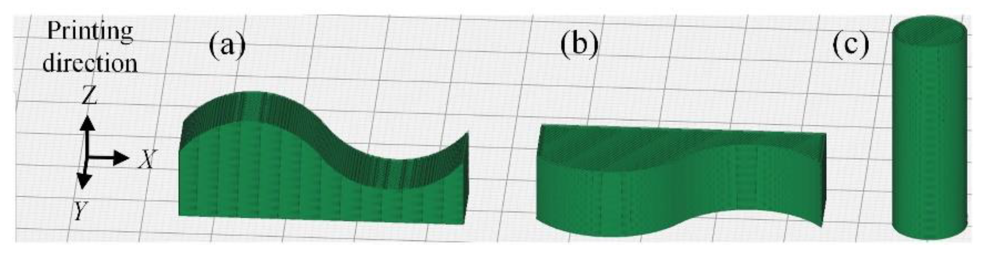
2.1. Specimens Preparation

The printing material used for the experiments is PEEK filament (5600 G, Changzhou, JS, China), 1.75 mm in diameter. Table 1 shows the typical material properties of PEEK. The AM machine is a self-designed fused deposition modeling additive manufacturing machine with a nozzle temperature of 450 °C, a bed temperature of 260 °C, and a print table size of 140 × 140 mm. As PEEK is often fabricated into a variety of curved parts in applications, the milled specimens for this experiment are designed to be 40 × 10 × 15 mm curved parts. Based on the principle that different AM printing directions affect the internal properties of the parts [41], here the milling specimens are printed in 2 groups at an angle of 0° and 90° to the Z direction, as shown in Figure 1. Based on existing studies and material manufacturers [38,42,43], the AM process parameters of the printing direction comparison experiment are set as shown in Table 2. Two specimens are prepared for each group (a) and (b) for milling post-processing in different directions.
To improve the shear strength of 3D-printed PEEK parts, the effects of three factors on shear strength, nozzle temperature, layer thickness, and bed temperature are studied by orthogonal experiment. The setup of orthogonal design levels based on existing studies is shown in Table 2. Three specimens are printed in each group and the test results are averaged. The shear strength test specimens are designed as a cylinder 10 mm in diameter and 30 mm in height, as shown in Figure 1.

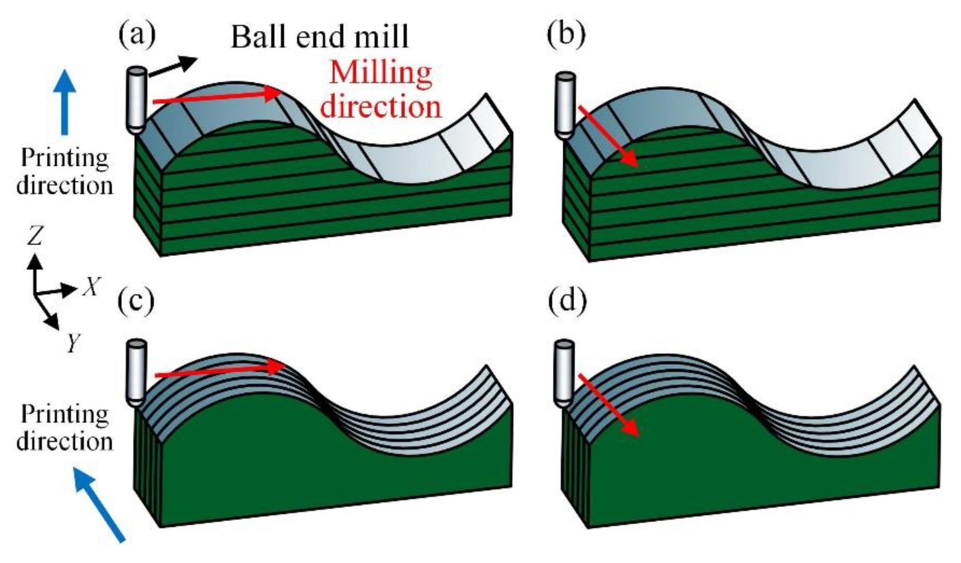
2.2. Milling Post-Processing

The milling post-processing is performed on a machining center Carver PMS23_A8. All milling post-processing in this research is carried out under dry conditions. According to the previous study, a 2 mm diameter carbide ball end mill is selected for the process and milling settings are a spindle speed of 4700 r/min, cutting depth of 0.2 mm, feed per tooth of 0.06 mm/z, and tool lateral sliding of 0.1 mm. To avoid the effects of the staircase effect on the surface of the 3D-printed parts, a 1 mm deep roughing process is first carried out on the surface of the parts. The specific milling solution is shown in Figure 2: the ball end mill mills the curved parts of the 0° and 90° printed specimens at the X and Y directions, respectively, for milling post-processing.

2.3. Testing

The shear strength test is carried out using a microcomputer-controlled electronic universal testing machine (E45.105, Eden Prairie, MN, USA) with a loading rate of 2 mm/min in reference to the GJB715.26A-2008 standard. The milled 3D-printed parts are measured for surface roughness values using a portable stylus-type contact roughness meter (TR200, Beijing, China). The sampling length is 0.8 mm, the assessment length is 4 mm, and the results are filtered using a Gaussian filter. Each group of specimens is measured a total of four times in the location and direction as shown in Figure 3, and the test results are averaged. Here, the measurement direction is not made all perpendicular to the milling direction because the delamination burr on the specimen surface is the main factor affecting the roughness value in this experiment. In addition, because the specimen is curved, a straight line contour can be measured only in the direction shown in Figure 3, which gives a more accurate result. Surface morphology is observed using a portable USB microscope (magnification range of 25× to 200×) with the observation area shown in Figure 3.

3. Results and Analysis

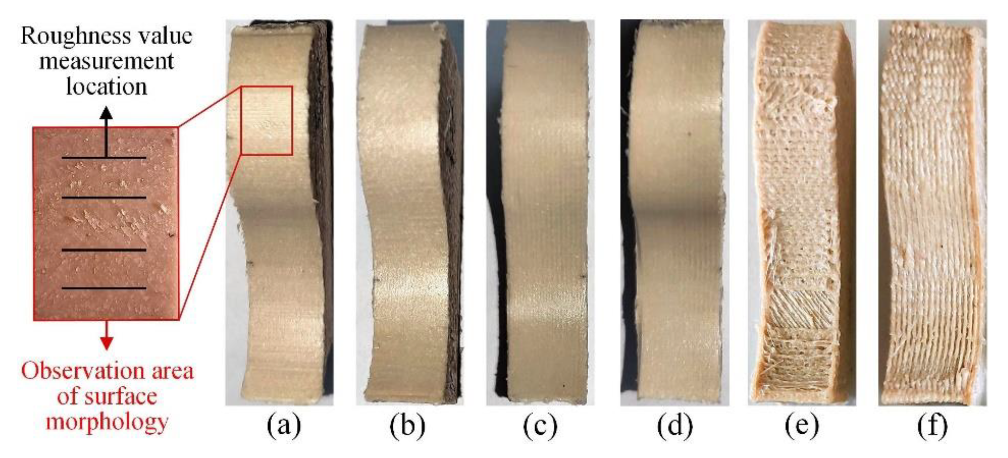
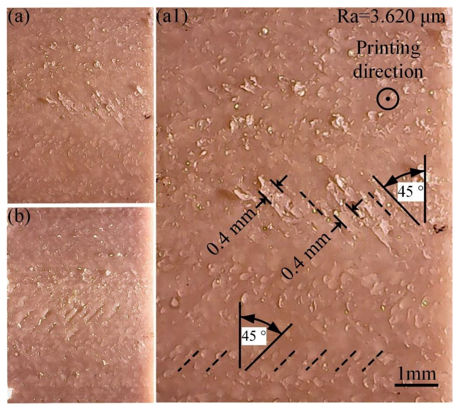
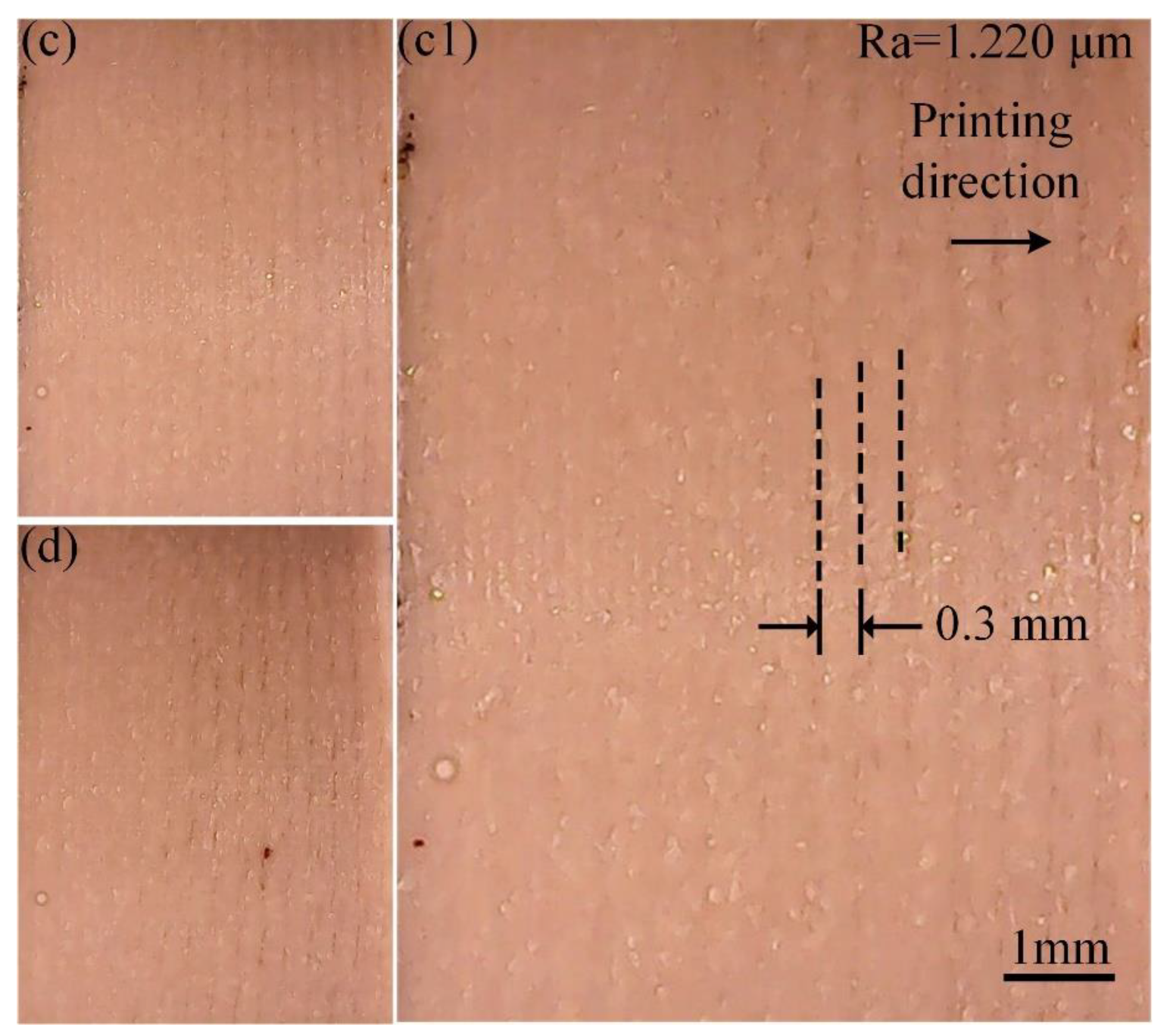
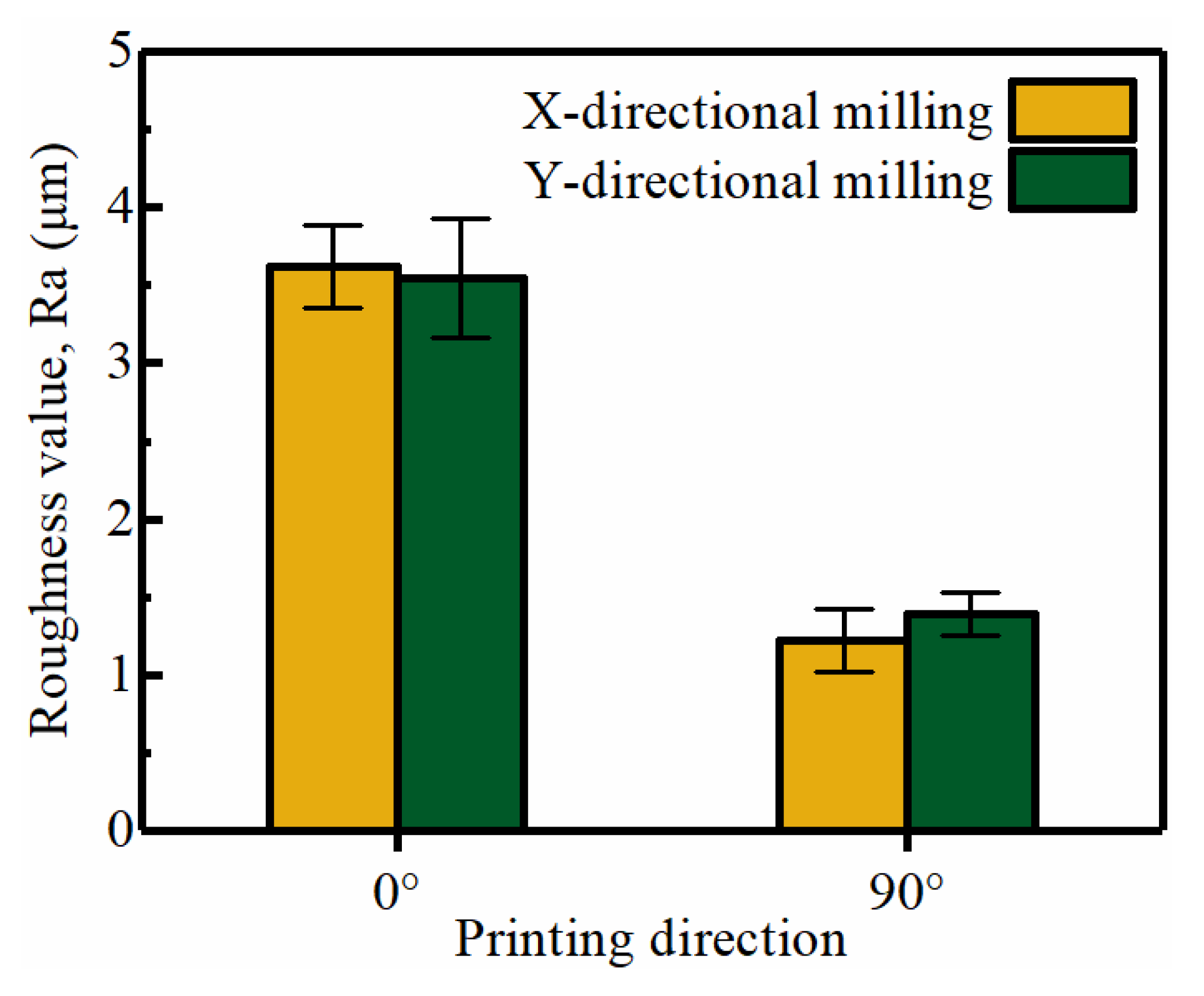
3.1. The Effects of the Directions on the Milling Quality

As shown in Figure 3, the surface quality of the milled specimens is significantly improved compared to the 3D-printed specimens. This indicates that it is indeed possible to improve the surface quality of 3D-printed specimens by the milling post-processing, thereby improving the durability and surface accuracy of PEEK parts. However, the surface morphology of the four sets of milling specimens is enlarged and observed, and some obvious problems and patterns are found between them.
As shown in Figure 4a,b, the surfaces of specimens (a) and (b) both have a large number of burrs and delaminations, and the measured Ra is 3.620 μm and 3.546 μm, respectively, and the surface quality is not much different. Therefore, specimen (a) is selected for machining surface morphology analysis. As can be seen from Figure 4a1, there are three main types of surface defects: the smaller burrs are concentrated in the upper part of the figure, the large burrs and whole strips of material falling off are concentrated in the middle of the figure, and the fine delaminations are the most numerous and are distributed over the entire milled surface. A closer look at the directions of these burrs (as indicated by the dashed lines in the diagram) reveals an overall orientation of ±45° and a maximum width of approximately 0.4 mm. The filling angle in the AM process is ±45° and the nozzle diameter is 0.4 mm, which corresponds to the burrs’ size and orientation. This indicates that these delaminations, burrs, and material peeling are actually the result of poor internal bonding of the material. The strips of material extruded from the nozzle are not firmly bonded to each other sufficiently; thus, under the effects of the milling force, the material is removed from its original position, which creates delaminations and burrs. These surface defects reduce the wear resistance and stability of the parts and seriously shorten the parts’ service life. It may even be scrapped outright due to excessive surface roughness values and dimensional errors, resulting in a waste of energy and material that is not in line with the green manufacturing concept.
As can be seen in Figure 5c,d, the surfaces of specimens (c) and (d) are almost free of burrs and obvious delaminations, and the measured Ra is 1.220 μm and 1.393 μm, respectively, and the surface quality is not much different. Therefore, specimen (c) is selected for machining surface morphology analysis. As can be seen from Figure 4c1, the surface of the specimen (c) is smooth and the machining quality is significantly better than that of specimens (a) and (b), with increasingly pronounced vertical lines appearing from left to right on the machined surface (as shown by the dashed lines in the diagram). These vertical lines are below the translucent PEEK surface layer and do not affect Ra or gloss. This indicates that only slight delaminations are formed on the machined surface and that these are eliminated by the smearing effect of milling [31]. These vertical lines are parallel to the printing direction and the distance between the two lines is 0.3 mm, the same as the printed layer thickness, which means that these lines are vertical interlayer bonding lines. The left side of the figure is the direction closest to the printing bed. As the printing height increases, the materials get further and further away from the printing bed. The temperature difference between the extruded material and the freshly extruded material will be even greater. As a result, the bonding strength between the layers gradually becomes smaller, the delaminations formed become larger and larger, and the vertical line pattern becomes more and more obvious. It appears that the delaminations of the milling post-processing may be related to the mechanical strength (material bond strength) of the 3D-printed parts. The difference in the milled surface morphology of the 0° and 90° printed specimens may be the result of differences in the mechanical strength of the 3D-printed parts in all directions.
As shown in Figure 6, by comparing the above surface morphology and roughness, it can be seen that the milled surface quality of (a) and (b), the two groups of specimens printed in 0° direction, is similar, and the milled surface quality of (c) and (d), the two groups printed in 90° direction, is similar, no matter the X or Y directions tool used for milling. This indicates that milling direction is not the main factor affecting the surface quality of milled 3D-printed PEEK parts, and the surface quality of the specimens with different printing directions appeared to be significantly different when compared to each other. The surface quality of specimens printed in the 90° direction is significantly better than that of specimens printed in the 0° direction. This indicates that the printing direction is the main reason for the machining quality. When milling post-processing 3D-printed PEEK parts, choosing a reasonable orientation for printing and milling the side of the parts according to actual needs can effectively improve the impact of parts with delamination defects. It can improve the success rate and surface quality of parts manufacturing, reduce the waste of energy and materials, and help to achieve lightweight and green manufacturing of parts.

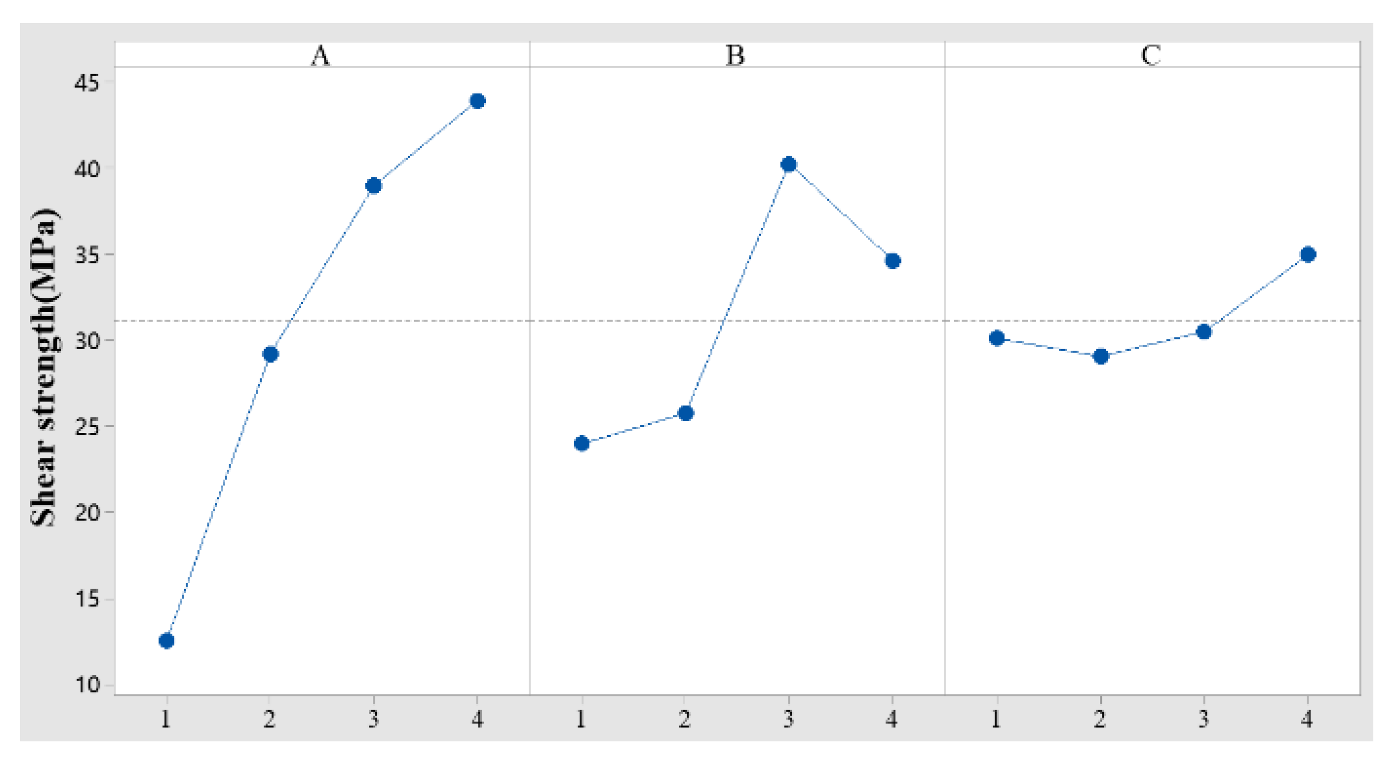
3.2. Effects of Process Parameters on Shear Strength

The results of the orthogonal experiment and the range analysis are shown in Table 3 and Table 4.
In Table 4, K1, K2, K3, and K4 denote the mean values of shear strength at four levels for factors A, B, and C. R denotes the range of each factor. The larger the R corresponding to the factor, the greater the effects on the shear strength represented. The R between A, B, and C in Table 4 are 30.61, 16.28, and 5.91, respectively. So the effects of the three factors on shear strength are A > B > C in order of strength, i.e., nozzle temperature > layer thickness > bed temperature. With the level of each factor as the horizontal coordinate and its corresponding mean value Ki of shear strength as the vertical coordinate, the plot of each factor versus shear strength is shown in Figure 7.
As seen in Figure 7, with the increase of the nozzle temperature, the shear strength of the specimens shows an increasing trend, reaching a maximum at the nozzle temperature of 450 °C, and the overall change is very significant. With the increase of the layer thickness, the shear strength shows a trend of first increasing and then decreasing, reaching the maximum at the layer thickness of 0.3 mm, and the overall change trend is relatively significant. With the increase in bed temperature, the shear strength shows a trend of first decreasing and then increasing, and it reaches the maximum at the bed temperature of 260 °C. The overall change trend is not significant. Based on the analysis of the above orthogonal experiment results, the optimal process parameters combination is determined as a nozzle temperature of 450 °C, layer thickness of 0.3 mm, and bed temperature of 260 °C. A set of shear specimens are prepared by AM according to the obtained process parameters combination, and the average shear strength of 52.13 MPa is tested and calculated. The predicted shear strength value obtained from the analysis using MINITAB software for the orthogonal array is 51.35 MPa. The shear strength of the optimized parts is close to that of injection-molded PEEK parts, greatly improving the mechanical strength and durability of 3D-printed PEEK parts.

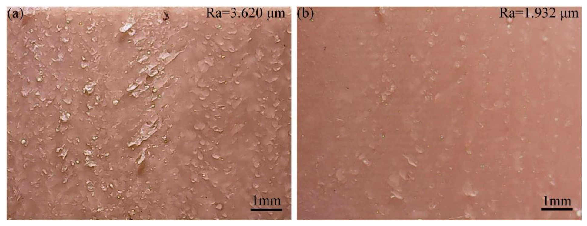
3.3. Effects of Mechanical Strength on Milling Quality

The comparative analysis in Section 3.1 reveals that the surface quality of the milling post-processing of 3D-printed parts may be related to mechanical strength. Therefore, in this section, the specimens printed using the optimal parameters combination of shear strength are subjected to milling post-processing and compared with the surface morphology of the milled specimens manufactured before optimization, as shown in Figure 8.
As can be seen from Figure 8, the milling surface of specimen (a) has a large number of burrs and delaminations on the surface, and there is a large size of material separation with poor machining surface quality. After shear strength optimization, the surface delaminations and burrs of specimen (b) are significantly reduced. This suggests that enhancing the mechanical strength of incremental PEEK by optimizing process parameters is accompanied by an increase in its corresponding post-processing quality.
However, the surface quality of the 3D-printed PEEK specimens fell short of that of the injection-molded parts. This may be due to the fact that the process of this research does not use advanced algorithms [44,45] and the optimization is not yet optimal. From the perspective of green manufacturing, the research content also lacks consideration of consumption time, cost, and energy [46]. These will be our next pieces of content to improve.

4. Conclusions

In this research, the FDM printing and milling post-processing processes are optimized to improve the surface quality and durability of the parts and to reduce the scrap rate and material waste of 3D-printed PEEK parts. The main conclusions are as follows:
(1)
The feasibility of improving the surface quality and dimensional accuracy of 3D-printed PEEK parts by milling post-processing is verified, and the application of 3D-printed PEEK parts is expanded.
(2)
The effects of two printing directions of 0° and 90°, and two milling directions of X and Y, on the surface quality of 3D-printed PEEK parts of milling post-processing are compared. It is found that the printing direction has significant effects on the milled surface quality of 3D-printed parts. Selecting the printing direction for AM according to the demand can improve the delaminations caused by milling and significantly enhance the surface quality of the milling post-processing.
(3)
The effects of three main AM process parameters, namely nozzle temperature, layer thickness, and bed temperature, on shear strength are investigated by orthogonal experiments and range analysis. The process parameters combination of AM for shear strength comparable to injection molded PEEK parts is obtained as follows: nozzle temperature 450 °C, layer thickness 0.3 mm, and bed temperature 260 °C.
(4)
By comparing the milled surface morphology of 3D-printed specimens before and after mechanical strength optimization, it is found that increasing the mechanical strength of 3D-printed parts can significantly improve the defects, such as surface delaminations and burrs, caused by milling post-processing.
This research successfully improves the durability and surface quality of 3D-printed PEEK parts by optimizing the machining process. It provides a reference for utilizing AM PEEK technology to achieve lightweight and green manufacturing.

Author Contributions

Conceptualization, H.Z., X.C. and X.J.; methodology, H.Z., X.C. and G.Z.; validation, H.Z., Y.L. and M.T.; data curation, J.Z. and Y.L.; writing—original draft preparation, H.Z.; writing—review and editing, X.C., G.Z. and X.J.; supervision, J.Z., M.T. and F.L.; project administration, H.Z., F.L. and X.J. All authors have read and agreed to the published version of the manuscript.

Funding

The paper is financially supported by the Natural Science Foundation of Shandong Province (ZR2020ME157) and Shandong Provincial Key Laboratory of Precision Manufacturing and Non-traditional Machining.

Institutional Review Board Statement

Not applicable.

Informed Consent Statement

Not applicable.

Data Availability Statement

All data generated or analyzed during this study are included in this published article. Compliance with ethical standards.

Conflicts of Interest

The authors declare that they have no conflict of interest.

References

  1. Ma, H.; Suonan, A.; Zhou, J.; Yuan, Q.; Liu, L.; Zhao, X.; Lou, X.; Yang, C.; Li, D.; Zhang, Y.-G. PEEK (Polyether-ether-ketone) and its composite materials in orthopedic implantation. Arab. J. Chem. 2021, 14, 102977. [Google Scholar] [CrossRef]
  2. Han, X.; Sharma, N.; Xu, Z.; Scheideler, L.; Geis-Gerstorfer, J.; Rupp, F.; Thieringer, F.M.; Spintzyk, S. An In Vitro Study of Osteoblast Response on Fused-Filament Fabrication 3D Printed PEEK for Dental and Cranio-Maxillofacial Implants. J. Clin. Med. 2019, 8, 771. [Google Scholar] [CrossRef] [Green Version]
  3. Thiruchitrambalam, M.; Bubesh Kumar, D.; Shanmugam, D.; Jawaid, M. A review on PEEK composites—Manufacturing methods, properties and applications. Mater. Today Proc. 2020, 33, 1085–1092. [Google Scholar] [CrossRef]
  4. Liu, Z.; Wang, L.; Hou, X.; Wu, J. Investigation on dielectrical and space charge characteristics of peek insulation used in aerospace high-voltage system. IEEJ Trans. Electr. Electron. Eng. 2019, 15, 172–178. [Google Scholar] [CrossRef]
  5. Haleem, A.; Javaid, M. Polyether ether ketone (PEEK) and its 3D printed implants applications in medical field: An overview. Clin. Epidemiol. Glob. Health 2019, 7, 571–577. [Google Scholar] [CrossRef] [Green Version]
  6. Dua, R.; Rashad, Z.; Spears, J.; Dunn, G.; Maxwell, M. Applications of 3D-Printed PEEK via Fused Filament Fabrication: A Systematic Review. Polymers 2021, 13, 4046. [Google Scholar] [CrossRef]
  7. Majeed, A.; Zhang, Y.; Ren, S.; Lv, J.; Peng, T.; Waqar, S.; Yin, E. A big data-driven framework for sustainable and smart additive manufacturing. Robot. Comput. Manuf. 2020, 67, 102026. [Google Scholar] [CrossRef]
  8. Madhavadas, V.; Srivastava, D.; Chadha, U.; Raj, S.A.; Sultan, M.T.H.; Shahar, F.S.; Shah, A.U.M. A review on metal additive manufacturing for intricately shaped aerospace components. CIRP J. Manuf. Sci. Technol. 2022, 39, 18–36. [Google Scholar] [CrossRef]
  9. Jayasudha, M.; Elangovan, M.; Mahdal, M.; Priyadarshini, J. Accurate Estimation of Tensile Strength of 3D Printed Parts Using Machine Learning Algorithms. Processes 2022, 10, 1158. [Google Scholar] [CrossRef]
  10. Wang, Y.; Ahmed, A.; Azam, A.; Bing, D.; Shan, Z.; Zhang, Z.; Tariq, M.K.; Sultana, J.; Mushtaq, R.T.; Mehboob, A.; et al. Applications of additive manufacturing (AM) in sustainable energy generation and battle against COVID-19 pandemic: The knowledge evolution of 3D printing. J. Manuf. Syst. 2021, 60, 709–733. [Google Scholar] [CrossRef]
  11. Cui, W.; Yang, Y.; Di, L.; Dababneh, F. Additive manufacturing-enabled supply chain: Modeling and case studies on local, integrated production-inventory-transportation structure. Addit. Manuf. 2021, 48, 102471. [Google Scholar] [CrossRef]
  12. Blakey-Milner, B.; Gradl, P.; Snedden, G.; Brooks, M.; Pitot, J.; Lopez, E.; Leary, M.; Berto, F.; du Plessis, A. Metal additive manufacturing in aerospace: A review. Mater. Des. 2021, 209, 110008. [Google Scholar] [CrossRef]
  13. Czerwinski, F. Current Trends in Automotive Lightweighting Strategies and Materials. Materials 2021, 14, 6631. [Google Scholar] [CrossRef] [PubMed]
  14. Schuhmann, D.; Rupp, M.; Merkel, M.; Harrison, D.K. Additive vs. Conventional Manufacturing of Metal Components: Selection of the Manufacturing Process Using the AHP Method. Processes 2022, 10, 1617. [Google Scholar] [CrossRef]
  15. Alam, F.; Varadarajan, K.M.; Koo, J.H.; Wardle, B.L.; Kumar, S. Additively Manufactured Polyetheretherketone (PEEK) with Carbon Nanostructure Reinforcement for Biomedical Structural Applications. Adv. Eng. Mater. 2020, 22, 2000483. [Google Scholar] [CrossRef]
  16. Yoon, H.S.; Lee, J.Y.; Kim, H.S.; Kim, M.S.; Kim, E.S.; Shin, Y.J.; Chu, W.S.; Ahn, S.H. A comparison of energy consumption in bulk forming, subtractive, and additive processes: Review and case study. Int. J. Precis. Eng. Manuf. Green Technol. 2015, 1, 261–279. [Google Scholar] [CrossRef]
  17. Ligon, S.C.; Liska, R.; Stampfl, J.; Gurr, M.; Mülhaupt, R. Polymers for 3D printing and customized additive manufacturing. Chem. Rev. 2017, 117, 10212–10290. [Google Scholar] [CrossRef] [Green Version]
  18. Günaydın, K.; Türkmen, H.S. Common FDM 3D printing defects. In Proceedings of the International Congress on 3D Printing (Additive Manufacturing) Technologies and Digital Industry 2018, Online, 19–21 April 2018. [Google Scholar]
  19. Kozak, J.; Zakrzewski, T. Accuracy problems of additive manufacturing using SLS/SLM processes. In Proceedings of the XIII International Conference Electromachining 2018, Bydgoszcz, Poland, 9–11 May 2018. [Google Scholar]
  20. Maleki, E.; Bagherifard, S.; Bandini, M.; Guagliano, M. Surface post-treatments for metal additive manufacturing: Progress, challenges, and opportunities. Addit. Manuf. 2021, 37, 101619. [Google Scholar] [CrossRef]
  21. Valentan, B.; Kadivnik, Ž.; Brajlih, T.; Anderson, A.; Drstvenšek, I. Processing poly (ether etherketone) an a 3D printer for thermoplastic modelling. Mater. Tehnol. 2013, 47, 715–721. [Google Scholar]
  22. Wang, P.; Zou, B.; Xiao, H.; Ding, S.; Huang, C. Effects of printing parameters of fused deposition modeling on mechanical properties, surface quality, and microstructure of PEEK. J. Mater. Process. Technol. 2019, 271, 62–74. [Google Scholar] [CrossRef]
  23. Tian, G.; Zhang, C.; Fathollahi-Fard, A.M.; Li, Z.; Zhang, C.; Jiang, Z. An Enhanced Social Engineering Optimizer for Solving an Energy-Efficient Disassembly Line Balancing Problem Based on Bucket Brigades and Cloud Theory. IEEE Trans. Ind. Inform. 2022, 2022, 1–11. [Google Scholar] [CrossRef]
  24. Tian, G.; Yuan, G.; Aleksandrov, A.; Zhang, T.; Li, Z.; Fathollahi-Fard, A.M.; Ivanov, M. Recycling of spent Lithium-ion Batteries: A comprehensive review for identification of main challenges and future research trends. Sustain. Energy Technol. Assess. 2022, 53, 102447. [Google Scholar] [CrossRef]
  25. Cao, Q.; Shi, Z.; Bai, Y.; Zhang, J.; Zhao, C.; Fuh, J.Y.H.; Wang, H. A novel method to improve the removability of cone support structures in selective laser melting of 316L stainless steel. J. Alloys Compd. 2021, 854, 157133. [Google Scholar] [CrossRef]
  26. Taşcıoğlu, E.; Kıtay, Ö.; Keskin, A.Ö.; Kaynak, Y. Effect of printing parameters and post-process on surface roughness and dimensional deviation of PLA parts fabricated by extrusion-based 3D printing. J. Braz. Soc. Mech. Sci. Eng. 2022, 44, 139. [Google Scholar] [CrossRef]
  27. Peng, X.; Kong, L.; Fuh, J.Y.H.; Wang, H. A Review of Post-Processing Technologies in Additive Manufacturing. J. Manuf. Mater. Process. 2021, 5, 38. [Google Scholar] [CrossRef]
  28. Chavez, L.A.; Ibave, P.; Wilburn, B.; Iv, D.A.; Stewart, C.; Wicker, R.; Lin, Y. The Influence of Printing Parameters, Post-Processing, and Testing Conditions on the Properties of Binder Jetting Additive Manufactured Functional Ceramics. Ceramics 2020, 3, 65–77. [Google Scholar] [CrossRef] [Green Version]
  29. De Oliveira Campos, F.; Araujo, A.C.; Munhoz, A.L.J.; Kapoor, S.G. The influence of additive manufacturing on the micromilling machinability of Ti6Al4V: A comparison of SLM and commercial workpieces. J. Manuf. Process. 2020, 60, 299–307. [Google Scholar] [CrossRef]
  30. Khan, M.A.; Jappes, J.W. Innovations in Additive Manufacturing; Springer: Berlin/Heidelberg, Germany, 2022. [Google Scholar]
  31. Guo, C.; Liu, X.; Liu, G. Surface Finishing of FDM-Fabricated Amorphous Polyetheretherketone and Its Carbon-Fiber-Reinforced Composite by Dry Milling. Polymers 2021, 13, 2175. [Google Scholar] [CrossRef]
  32. Al-Rubaie, K.S.; Melotti, S.; Rabelo, A.; Paiva, J.M.; Elbestawi, M.A.; Veldhuis, S.C. Machinability of SLM-produced Ti6Al4V titanium alloy parts. J. Manuf. Process. 2020, 57, 768–786. [Google Scholar] [CrossRef]
  33. Cococcetta, N.; Jahan, M.P.; Schoop, J.; Ma, J.; Pearl, D.; Hassan, M. Post-processing of 3D printed thermoplastic CFRP composites using cryogenic machining. J. Manuf. Process. 2021, 68, 332–346. [Google Scholar] [CrossRef]
  34. Zimmermann, M.; Müller, D.; Kirsch, B.; Greco, S.; Aurich, J.C. Analysis of the machinability when milling AlSi10Mg additively manufactured via laser-based powder bed fusion. Int. J. Adv. Manuf. Technol. 2020, 112, 989–1005. [Google Scholar] [CrossRef]
  35. Ni, C.; Zhu, L.; Zheng, Z.; Zhang, J.; Yang, Y.; Hong, R.; Bai, Y.; Lu, W.F.; Wang, H. Effects of machining surface and laser beam scanning strategy on machinability of selective laser melted Ti6Al4V alloy in milling. Mater. Des. 2020, 194, 108880. [Google Scholar] [CrossRef]
  36. Basgul, C.; Yu, T.; MacDonald, D.W.; Siskey, R.; Marcolongo, M.; Kurtz, S.M. Does annealing improve the interlayer adhesion and structural integrity of FFF 3D printed PEEK lumbar spinal cages? J Mech Behav Biomed Mater. 2020, 102, 103455. [Google Scholar] [CrossRef]
  37. El Magri, A.; El Mabrouk, K.; Vaudreuil, S.; Chibane, H.; Touhami, M.E. Optimization of printing parameters for improvement of mechanical and thermal performances of 3D printed poly(ether ether ketone) parts. J. Appl. Polym. Sci. 2020, 137, 49087. [Google Scholar] [CrossRef]
  38. Sikder, P.; Challa, B.T.; Gummadi, S.K. A comprehensive analysis on the processing-structure-property relationships of FDM-based 3-D printed polyetheretherketone (PEEK) structures. Materialia 2022, 22, 101427. [Google Scholar] [CrossRef]
  39. Wang, P.; Zou, B.; Ding, S.; Li, L.; Huang, C. Effects of FDM-3D printing parameters on mechanical properties and microstructure of CF/PEEK and GF/PEEK. Chin. J. Aeronaut. 2021, 34, 236–246. [Google Scholar] [CrossRef]
  40. Schuett, M.; Karsten, J.; Schott, L.; Wittich, H.; Schulte, K.; Fiedler, B. Experimental and analytical study of an CF-PEEK Fastener all composites single-lap shear joint under static and fatigue loading. CEAS Aeronaut. J. 2019, 10, 565–587. [Google Scholar] [CrossRef]
  41. Zheng, J.; Kang, J.; Sun, C.; Yang, C.; Wang, L.; Li, D. Effects of printing path and material components on mechanical properties of 3D-printed polyether-ether-ketone/hydroxyapatite composites. J. Mech. Behav. Biomed. Mater. 2021, 118, 104475. [Google Scholar] [CrossRef]
  42. Liu, H.; Cheng, X.; Yang, X.H.; Zheng, G.M.; Guo, Q.J. Experimental study on parameters of 3D printing process for PEEK materials. IOP Conf. Ser. Mater. Sci. Eng. 2019, 504, 012001. [Google Scholar] [CrossRef]
  43. Zhao, Y.; Zhao, K.; Li, Y.; Chen, F. Mechanical characterization of biocompatible PEEK by FDM. J. Manuf. Process. 2020, 56, 28–42. [Google Scholar] [CrossRef]
  44. Tian, G.; Chu, J.; Liu, Y.; Ke, H.; Zhao, X.; Xu, G. Expected energy analysis for industrial process planning problem with fuzzy time parameters. Comput. Chem. Eng. 2011, 35, 2905–2912. [Google Scholar] [CrossRef]
  45. Yu, D.; Zhang, X.; Tian, G.; Jiang, Z.; Liu, Z.; Qiang, T.; Zhan, C. Disassembly Sequence Planning for Green Remanufacturing Using an Improved Whale Optimisation Algorithm. Processes 2022, 10, 1998. [Google Scholar] [CrossRef]
  46. Tian, G.; Liu, Y.; Ke, H.; Chu, J. Energy evaluation method and its optimization models for process planning with stochastic characteristics: A case study in disassembly decision-making. Comput. Ind. Eng. 2012, 63, 553–563. [Google Scholar] [CrossRef]
Figure 1. Printing of specimens: (a) 0° printing of curved specimens; (b) 90° printing of curved specimens; (c) shear test specimens.
Processes 10 02561 g001
Figure 2. Specimens milling methods: (a) 0° printing, milling at the X direction; (b) 0° printing, milling at the Y direction; (c) 90° printing, milling at the X direction; (d) 90° printing, milling at the Y direction.
Processes 10 02561 g002
Figure 3. Specimen milling before and after comparison and surface quality testing location: (a) 0° printing, milling at the X direction; (b) 0° printing, milling at the Y direction; (c) 90° printing, milling at the X direction; (d) 90° printing, milling at the Y direction; (e) 0° printing; (f) 90° printing.
Processes 10 02561 g003
Figure 4. Surface morphology of milled specimens: (a) 0° printing, milling at the X direction; (b) 0° printing, milling at the Y direction; (a1) enlarged image of subfigure (a).
Processes 10 02561 g004
Figure 5. Surface morphology of milled specimens: (c) 90° printing, milling at the X direction; (d) 90° printing, milling at the Y direction; (c1) enlarged image of subfigure (c).
Processes 10 02561 g005
Figure 6. Comparison of surface roughness values of milled specimens.
Processes 10 02561 g006
Figure 7. Effects of three factors on shear strength: (A) nozzle temperature; (B) layer thickness; (C) bed temperature.
Processes 10 02561 g007
Figure 8. Comparison of surface morphology before and after shear strength optimization: (a) before optimization; (b) after optimization.
Processes 10 02561 g008
Table 1. Material properties of the tested PEEK.
ItemValue
Density (g/cm3)1.30
Tensile strength (MPa)85
Shear strength (MPa)60
Flexural strength (MPa)150
Compression strength (MPa)118
Glass transition temperature (°C)143
Melting temperature (°C)343
Thermal conductivity (W/(m·K))0.25
Friction coefficient0.32
Table 2. AM process parameters.
Process ParametersPrinting Direction ComparisonOrthogonal Design Levels
FilamentsPEEK 5600 G
Nozzle diameter (mm)0.4
Printing speed (mm/s)40
Raster angle±45°
Infill patternLinear
Infill density100%
Printing direction0°, 90°
Nozzle temperature (°C)400360, 390, 420, 450
Layer thickness (mm)0.30.1, 0.2, 0.3, 0.4
Bed temperature (°C)200155, 190, 225, 260
Table 3. Results of the orthogonal experiment.
No.FactorsShear Strength (MPa)
A
Nozzle Temperature
(°C)
B
Layer Thickness
(mm)
C
Bed Temperature
(°C)
13600.11556
23600.21909.33
33600.322516.57
43600.426018.04
53900.119013.89
63900.215522.6
73900.326050.17
83900.422529.98
94200.122534.95
104200.226030.54
114200.315545.81
124200.419044.5
134500.126041
144500.222540.38
154500.319048.39
164500.415545.89
Table 4. Results of the range analysis.
ProjectsABC
K112.4923.9629.26
K229.1625.7129.03
K338.9540.2430.47
K443.133.7934.94
R30.6116.285.91
Publisher’s Note: MDPI stays neutral with regard to jurisdictional claims in published maps and institutional affiliations.

