Article

Evaluation of the Reliability and Lifetime Prediction of 150 GHz Athermal AWG Module with Metal Temperature Compensation Board

1
AI Convergence Research Section, Electronics and Telecommunications Research Institute, Gwangju 61012, Korea
2
School of Mechanical Engineering, Chonnam National University, 77 Yongbong-ro, Buk-gu, Gwangju 61186, Korea
3
PPI Inc., 958-10 Dae-chon dong, Buk-gu, Gwangju 61008, Korea
*
Author to whom correspondence should be addressed.
Processes 2022, 10(10), 2120; https://doi.org/10.3390/pr10102120
Submission received: 6 September 2022 / Revised: 7 October 2022 / Accepted: 15 October 2022 / Published: 18 October 2022
(This article belongs to the Special Issue Reliability and Engineering Applications)

Abstract

:
We have developed a 17-channel (150 GHz-spacing) athermal arrayed waveguide grating (AAWG), which has a wider operation range than that of the existing AWGs, by designing a metal structure assembly that reduces the temperature dependence of the wavelength. For an operation temperature range from −40 °C to 85 °C, the center wavelengths of all channels had a wavelength stability of ±0.04 nm and the insertion loss variation was less than ±0.78 dB. The accelerated life test showed that the predicted service life was expected to be more than 41.7 years.

1. Introduction

The exponential increase in traffic over the Internet continues with the advent of bandwidth-hungry applications such as 5G, video, artificial intelligence, and virtual/augmented reality [1]. In addition, digital activities using electronic devices have also rapidly increased with the outbreak of the COVID-19 pandemic. The rapidly increasing data traffic can be handled through 5G mobile networks, which supply 100 times faster traffic throughput than 4G networks, Giga-bit service per user, a short queue time, and high spectrum efficiency [2].
One example of network architecture designed to address those bandwidth-intensive services involves the use of a Wavelength-Division-Multiplexed Passive Optical Network (WDM-PON), which utilizes the dedicated point-to-point communications between the central office and the end users. In these WDM-PONs, the wavelength multiplexer or demultiplexer should be used for either combining or splitting the wavelengths at each allocated channel. To this application, an arrayed waveguide grating (AWG) filter has been extensively developed in recent decades and successfully deployed in the WDM networks [3,4,5].
For further deployment in the passive WDM networks such as 5G networks and WDM-PONs, an AWG filter should be capable of athermal operation within the harsh temperature range, for example, from −40 °C to 85 °C [6,7]. Here, the athermal operation means the AWG performance variation should be within the allowed range that can be tolerated in the network operation [8].
Electronic control circuitry for cooling the AWG unit is essential for the wavelength stabilization of each AWG channel over the temperature range of −40 °C to 85 °C.
Such additional requirements may increase the power budget, the cost/volume of the device, the chance of reliability problems, etc., and put a great burden on network operators and administrators [9,10].
In contrast, an athermal AWG (AAWG) requires neither of an active component nor an external electric power supply, keeping the total cost of network installation and maintenance much lower than that of a cooled AWG [11,12,13,14,15]. The center wavelength at each channel of an AWG made with silica material normally has a temperature dependence of around 11 pm/°C [16,17,18].
There have been numerous reports regarding the mechanical design skims for the athermal operation of the AWG filter module [11,12,13,14,15]. Reliability tests and lifetime predictions of a 50 GHz AAWG module, equipped with the temperature compensated operation, have already been conducted by using a metal structure; the results were reported in [15].
In this work, we show the improved reliability of an AAWG module with an elaborated fixture design in which the input slab waveguide moves in parallel with the slab. Moreover, our proposed design is developed in a manner of applying adhesive to minimal areas only where the AWG chips require bonding. To confirm the enhanced performance, we carry out a reliability test of the 17-channel (150 GHz-spacing) AAWG module and the results revealed a stable operation with only a ±0.04 nm wavelength shift (less than half of that demonstrated in [15]) and a long lifetime of 41.7 years (5 years longer than the results of [15]).

2. Design of the Athermal AWG

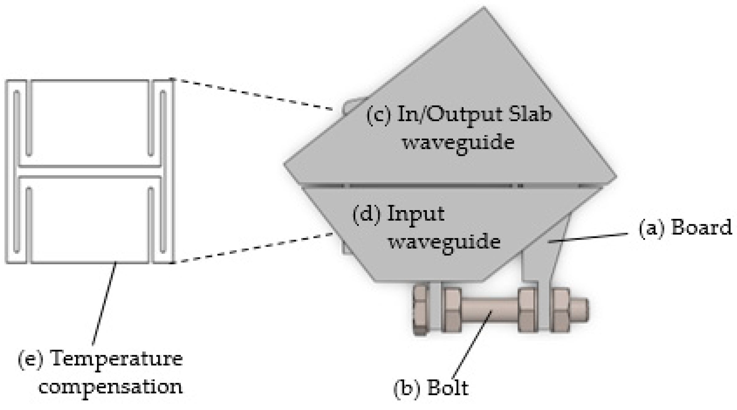
2.1. Thermal Compensation Design

With the typical AWG structure shown in Figure 1, the phase matching condition at each input/output waveguide is normally expressed as
n s   D sin +   n c Δ L = m λ
where ns and nc are the effective index of the slab and the waveguide, respectively. The spacing and angular difference between adjacent waveguides are D and ∅, respectively. The length difference in the arrayed waveguide arm is ΔL. The vacuum wavelength is λ, and the diffraction order is m.
From the dispersion relation of Equation (1), the following two equations for temperature dependence and angular dispersion are derived.
Equation (2) shows the temperature dependence of the center wavelength (C.W.) of each channel, whereas Equation (3) shows the angular dispersion for the change of the input wavelength from the C.W. For thermal compensation, the lateral displacement of the focal point ‘dx’ for the temperature change ‘dT’ should be compensated by moving the input or output waveguide in the opposite direction by ‘-dx’. Hence, it can be directly calculated by
d λ d T = λ     d n C n c   d T   +   λ α s
d x d λ = L f   Δ L n s   D λ 0   n g
where αs is the coefficient of thermal expansion (CTE) of the substrate. The substrate material is usually a silicon and its value is around 8 × 10⁻⁶/°C. The group index of the arrayed waveguide is ng. Lf is the focal length of the slab region. The C.W. of each channel is λ0. The variable ‘x’ denotes the lateral displacement of the focal point when the input wavelength is deviated from the C.W. λ0.
d x d T = ( L f   Δ L n s   D λ 0   n g )   d λ d T = ( L f   Δ L n s   D λ 0   n g ) ( λ     d n C n c   d T   +   λ α s )
Figure 2 illustrates the structure of the newly designed AAWG. Temperature compensating substrate (a) is Invar, (b) is an SUS bolt(S.B.), and (e) is designed to be structurally modulated by the thermal expansion of the SUS bolt. The input slab region of the AWG chip cuts into two parts, (c) and (d). Part (d) contains the input waveguide, whereas part (c) includes all the remaining regions of the AWG chip such as the input slab waveguide, the arrayed waveguide arm, the output slab, and the output waveguides. Below the AWG chips exists the board (a), which holds part (d).
The AWG chip (c, d) are adhesive-bonded only to the board (a) and such a skim of minimizing the thermal deformation can potentially guarantee a higher reliability of the AAWG module. The geometry of board (a), illustrated in (e), is elaborated in such a way as to enable the movement of (d) in parallel with the slab waveguide.
One end of the S.B. (b), of which the material is SUS (stainless steel), is connected to the board (a), and the other end is connected to part (c). When the environment temperature changes by 1 degree, then the S.B. (b) length changes by the amount of the product of the S.B. (b) length and its thermal expansion coefficient (1.73 × 10⁻⁵/°C).
By inserting the design parameters illustrated in Table 1 into Equation (5), we obtain the following.
d x d T = 0.197   μ m deg
Equation (5) demonstrates that, when the temperature changes by 1 °C, the focal point in the input end of the input slab waveguide shifts laterally by 0.197 μm. Hence, to thermally compensate for this shift, the S.B. (b) length is calculated by dividing this value by its thermal expansion coefficient, and its length becomes 11.4 mm.

2.2. Finite Analysis of Temperature Compensation Board

Figure 2 shows the structure of the multiplexing AAWG. This circuit consists of an integrated chip, a temperature compensation board (a), and an S.B. (b). The chip is cut at the input slab waveguide and separated into (c) and (d). The integrated chip is firmly attached to the upper side of the temperature compensation board (a) using a thermosetting adhesive and separated into (c) and (d). The loss is minimized using a matching gel.
In addition, the temperature compensation board (a) is connected to the S.B. (b) to compensate for temperature change. Thus, it is mainly thermally contracted and expanded in the X direction. The change in the compensation length in the X direction causes the waveguide to displace in the direction of the cut where the wavelength shift is compensated.
The deformation caused by the temperature of the compensation structure, in turn caused by the temperature compensation board, was simulated using a finite element method. Figure 3 shows the displacement in the X axis at a temperature of −40, −20, 0, 25, 55, and 85 °C. The displacement contraction from the reference location was indicated by + and the expansion was indicated by −.
In Figure 3a, the deformation caused by the temperature of the temperature compensation board at −40 °C and the displacement of the focal point due to the contraction of the temperature compensation bolt were around 5.03 μm. The difference in the wavelength shift was around 4 pm, which indicated that temperature compensation was well achieved. In Figure 3b, the deformation caused by the temperature of the temperature compensation board at −20 °C and the displacement for position compensation were around 3.47 μm; the difference in the wavelength shift was around 1 pm. Figure 3c describes that the displacement for position compensation at 0 °C was 1.93 μm, and the difference in wavelength shift was around 2 pm.
As shown in Figure 3d, the AWG temperature compensation board and bolt practically maintain their original shape without significant change at room temperature (25 °C). Figure 3e describes the deformation caused by the temperature in the temperature compensation board at 55 °C; the displacement for position compensation was around −2.34 μm, and the difference in wavelength shift was around 11 pm. Figure 3f presents the deformation caused by the temperature in the temperature compensation board at 85 °C; the displacement for position compensation was around −4.67 μm and the difference in wavelength shift was around 9 pm.
The displacement value for position compensation was almost consistent with the theoretical design (the pitch of adjacent arrayed waveguide 7.0 μm) (the difference was around 1 pm to 11 pm). The loss was expected to be low because the wavelength shift was well compensated for according to the temperature change [13].

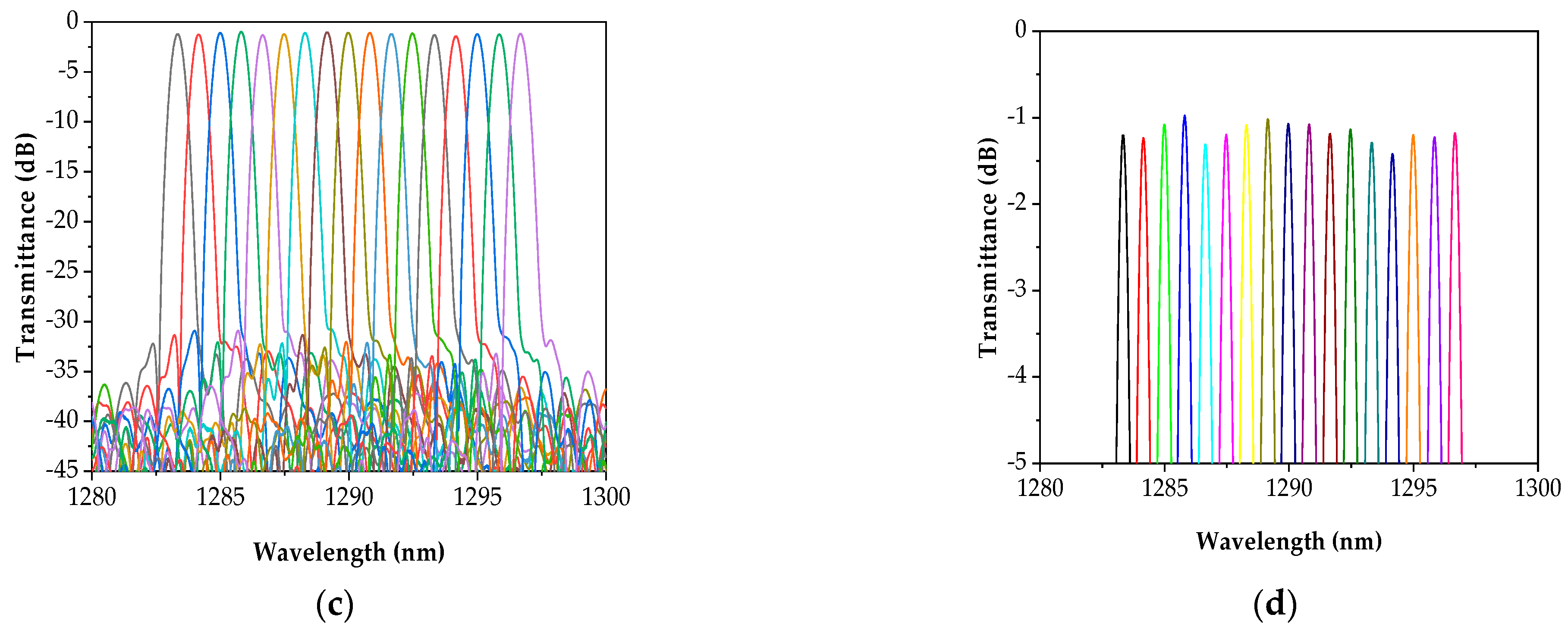
3. Athermal AWG Fabrication Results

Fabrication Results

We fabricated a Gaussian-type AAWG module by minimizing the 17-channel (150 GHz-spacing) AWG chip manufactured using the PLC manufacturing technology into 95 × 55 × 12 mm, as shown in Figure 4, based on the temperature compensation principle and our patent [19]. The newly manufactured module simplified the process by minimizing the epoxy, and the wavelength shift was two times smaller than the previously developed (50 GHz-spacing) AAWG due to the improvement of the temperature compensation structure, so the yield was also improved.
The reliability and characteristics tests of optical communication components followed international testing standards [20,21]. Based on the conditions of international testing standards [20], the reliability testing of the AAWG module was conducted, and the characteristic performance was measured before and after testing at room temperature (23 °C, 50% R.H.).
Table 2 presents the results of the mechanical shock and long-term environment reliability tests. The reliability test was conducted with three samples for each test and the insertion loss(IL) value and C.W. were compared before and after the test at room temperature.
Figure 5a shows the spectral response of one sample before the testing of 17-channel AAWG modules. Figure 5b–d shows the monitored wavelength and IL deviation in real-time according to temperature changes while conducting the temperature cycling reliability test. The IL and C.W. shift at the No. 9 channel were measured while conducting the temperature cycling test (−40~85 °C). The temperature dependence of the C.W. for the wavelength (9 ch.) of the 150 GHz × 17 channels AWG module is shown in (b), which verifies that the value required by the temperature compensation was satisfied. The temperature dependence of the IL for the wavelength (9 ch.) of three AAWG modules in a range of −40~85 °C is shown in (c), which verifies that the temperature was compensated for from the minimum ±0.001 nm to the maximum ±0.04 nm. The C.W. shift of three AAWG modules in a range of −40~85 °C is shown in (d), which also verifies the deviation ranges from the minimum ±0.01 dB to the maximum ±0.78 dB.

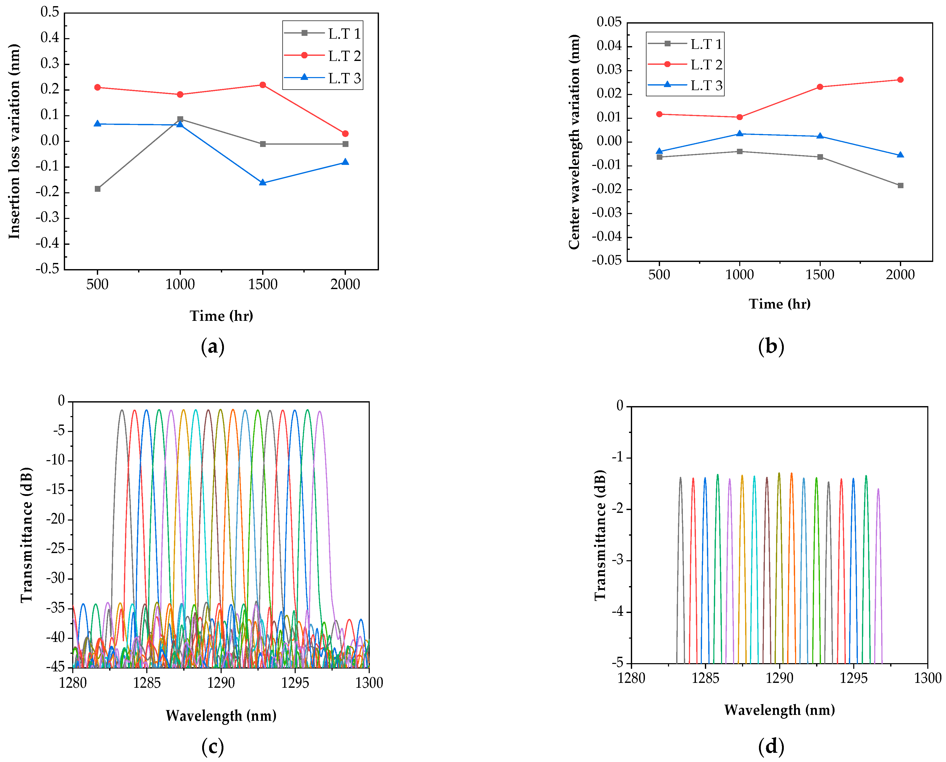
4. Reliability Test Results for Internal and External Environmental Application

Reliability Tests Result

The reliability test of the 17-channel (150 GHz-spacing) AWG modules was conducted by referring to international testing standards [20,21] for passive optical components, and compared to the test on the previously developed product (50 GHz-spacing, 96 ch., AWG). Additionally, a harsher test condition was applied by adding an impact test and increasing the test cycle. The reliability test results were analyzed as shown in Table 2. The wavelength band was 1280~1300 nm, and the channel spacing was around 0.83 nm. To verify the reliability of the AAWG module, three samples for each test item were tested. To compare the sample’s performance, IL before and after the test, IL deviation, and C.W. were measured.
As presented in the results of Table 2, according to the conditions of the reliability test, the measured maximum IL deviation was within the maximum ±0.40 dB, which satisfied the requirements of 0.5 dB or 10% by the above specifications. The average IL is an average of 1~17 channels in three samples, which were individually tested. It showed a range within the maximum of −2.20 dB, which was smaller than the reference value of 4.6 dB in international testing standards [21]. Among the six items in the reliability test, the largest average IL was −2.20 dB, which was found in the cycling moisture resistance test. The average IL deviation (two in mechanical items and four in environment items) of the six items in the reliability test was in a range of −0.20~0.11 dB, which verified the performance was stably maintained even after the reliability test without any significant differences. The average C.W. temperature dependence satisfied a range of ±0.007 nm and the average IL deviation was less than ±0.2 dB in all test items.
Figure 6 shows the average results of 17 channels in three AAWG modules after the temperature cycling test. Figure 6a,b shows the IL deviation and C.W. shift. The IL deviation after the test of 2000 cycles at −40~85 °C was within ±0.11 dB and the C.W. shift was within ±0.007 nm, which exhibited a stable performance against temperature changes. Figure 6c shows the stable spectrum after the temperature cycling.
Figure 7 shows the average results of 17 channels in three AAWG modules after 2000 h at 85 °C in the high storage temperature test. Figure 7a shows that the IL deviation was within ±0.20 dB and the C.W. shift was within ±0.003 nm, which exhibited a stable performance even in long-term, high-temperature environments. Figure 7c shows the stable spectrum after the high storage temp.
Figure 8 shows the average results of 17 channels in three AAWG modules after 2000 h at −40 °C in the low storage temperature test. Figure 8a shows that the IL deviation was within ±0.02 dB and the C.W. shift was within ±0.001 nm, which exhibited a stable performance even in long-term, low-temperature environments. Figure 8c shows the stable spectrum even after the low storage temperature test.
As shown in Table 2, the reliability test results of the 17-channel (150 GHz-spacing) AAWG modules verified that the performance degradation of communication quality was small in the reliability test consisting of two mechanical items (vibration and mechanical tests) and four environmental items. The purpose of these tests is to guarantee the reliability of the module, which will be used in an optical communication network for a long period.

5. Lifetime Prediction

5.1. Accelerated Life Test

To predict the lifetime of the developed product, an accelerated life test was conducted with the 17-channel (150 GHz-spacing) AAWG module at a high temperature. The life–stress relationship was estimated using the Arrhenius equation in the accelerated life test as accelerated stress caused by temperature. The test conditions were set in consideration of stress extrapolation and time extrapolation [15,22].

5.1.1. Preparation

Table 3 presents the conditions of the accelerated life test on the AAWG sample. Compared to the test conditions for the product developed in 2021, the accelerated lifetime test applies a higher temperature (3 to 5 degrees higher) for an extended period (300 h).
To increase the reliability of the lifetime prediction, intermediate measurements were conducted at three temperatures (74, 86, and 100 °C) with intervals of 250 h. The accelerated life test was conducted for 4300 h using three high-temperature chambers (ESPEC), optical spectrum analysis (Anritsu, ms9740A), and Optical Source (Amonics). Failure criteria were established during the test. Failure was deemed to have occurred if there were accident failures or there was a 50% change from the initial measurement. The 28 samples (21 of Gaussian type and 7 of flat type) were distributed by three temperatures. Channels No. 1 and No. 17 were measured to enhance the data reliability [15].

5.1.2. Accelerated Life Test Model

In order to find a suitable life distribution for the data measured during the 4300 h accelerated life test, ALTA S/W was used to compare the likelihood function values of the lognormal distribution, Weibull, and exponential distribution, as shown in Table 4. The comparison results of the likelihood function in three life distributions showed that the Lognormal distribution was the largest, which was found as the suitable life distribution. Figure 9 shows the graph of analyzing the failure value measured. Failure data under accelerated test conditions are closely arranged in a straight line. Furthermore, since the life distribution estimate lines are parallel, it can be predicted that the acceleration was established and the lognormal distribution was suitable [15].

5.1.3. Life–Stress Relationship and Acceleration Factor

For an optimal life distribution model, a lognormal distribution was suitable. The life–stress relationship of the accelerated life test by temperature is calculated using the Arrhenius relationship, as in Equation (6) [15].
ζ(T) = A · exp [E/(kT)]
From the life–stress relationship, the acceleration factor (A.F(T)) can be found as presented in Equation (7) [15].
A.F(T) = ζ(Ta)/ζ(Ts) = exp[(E/K)·(1/Ta − 1/Ts)]
where Ta refers to the life in the application condition and Ts refers to the life in the stress condition.
The activation energy (Ea) was estimated to be 0.532 using ALTA software. The A.F(T) was calculated for each acceleration stress. The life–stress relationship at temperatures of 74 °C, 86 °C, and 100 °C predicted that rapid failure would occur and the life was shortened as the temperature rose, as shown in Figure 10.

5.2. High Temperature Accelerated Life Test Result of Athermal AWG Module

Table 5 summarizes the failure results that occurred under the conditions of the high temperature test for 4300 h in the accelerated life test.
The samples were composed of 28 AAWGs (Flat 7, Gaussian 21) of 17-, 48-, and 96-channels (50 and 150 GHz-spacing). Mainly, three failures were found in the Gaussian type only. After completing the accelerated life test, a representative 150 GHz sample was selected and the IL of the No. 1 channel was measured as shown in Figure 11. After the high-temperature accelerated life test for 4300 h, the I/L was −1.41 dB at 74 °C, –1.73 dB at 86 °C, and –2.43 dB at 100 °C. The IL deviation was −0.01 dB at 74 °C, –0.06 dB at 86 °C, and –0.17 dB at 100 °C, which showed a larger IL deviation at high temperature.
In addition, the measurement results of the high-temperature accelerated life test for 4300 h satisfied the standards of Telcordia-GR-1209, and the wavelength and characteristics exhibited a stably reliable performance as shown in Figure 11.
The AAWG module in the accelerated life test with the high-temperature stress followed a lognormal distribution. The prediction results showed that the activation energy was 0.532 eV, which was calculated using ALTA software, and its mean life was around 3.65 × 10⁵ (around 41.7 years) at an operating condition of 40 ℃. Thus, the prediction results proved that a life of 10 years or longer can be sufficiently guaranteed for the stability and long-term reliability of communication quality in optical communication systems.

6. Conclusions

The C.W. temperature dependence of the 17-channel (150 GHz-spacing) AAWG module, which was developed based on a new shape and our patent of a temperature compensation board of a metal structure, satisfied a range of ±0.04 nm in all channels between temperatures of −40 °C and 85 °C, with an IL deviation which was also less than ±0.78 dB. In addition, the reliability test was conducted to validate the AAWG based on international testing standards, which are the testing standards for optical communication components; the results showed that the average C.W. temperature dependence satisfied a range of ±0.007 nm, and the average IL deviation was also less than ±0.2 dB. In the high-temperature accelerated life test of the AWG module for the lifetime prediction, the predicted mean life was around 3.65 × 10⁵ (around 41.7 years) at an operating condition of 40 °C. The developed AAWG module guarantees a life of 10 years or longer, with sufficient communication quality performance and reliability verification that can be used in communication networks.

Author Contributions

Conceptualization, K.-S.Y., C.-H.Y., W.-C.K. and I.J.; methodology, K.-S.Y. and C.-H.Y.; software, K.-S.Y.; validation, C.-H.Y. and I.J.; formal analysis, K.-S.Y. and W.-C.K.; investigation, K.-S.Y., W.-C.K. and S.-Y.K.; data curation, K.-S.Y., C.-H.Y. and S.-Y.K.; writing—original draft preparation, K.-S.Y.; writing—review and editing, K.-S.Y., C.-H.Y. and W.-C.K.; visualization, K.-S.Y.; project administration, K.-S.Y. and K.-S.L.; funding acquisition, K.-S.L. All authors have read and agreed to the published version of the manuscript.

Funding

This research was financially supported by an Electronics and Telecommunications Research Institute (ETRI) grant funded by the Korean government [22ZK1100, Honam region regional industry-based ICT convergence technology advancement support project].

Data Availability Statement

Not applicable.

Conflicts of Interest

The authors declare no conflict of interest.

References

  1. Pittalà, F.; Braun, R.P.; Böcherer, G.; Schulte, P.; Schaedler, M.; Bettelli, S.; Calabrò, S.; Kuschnerov, M.; Gladisch, A.; Westphal, F.-J.; et al. 1.71 Tb/s single-channel and 56.51 Tb/s DWDM transmission over 96.5 km field-deployed SSMF. IEEE Photonics Technol. Lett. 2022, 34, 157–160. [Google Scholar] [CrossRef]
  2. Pandey, G.; Choudhary, A.; Dixit, A. Wavelength Division Multiplexed Radio Over Fiber Links for 5G Fronthaul Networks. IEEE J. Sel. Areas Commun. 2021, 39, 2789–2803. [Google Scholar] [CrossRef]
  3. Luo, Y.; Chanclou, P.; Skouby, K.E.; Zhao, H.; Asaka, K. Guest Editorial: Enhanced Fronthaul for 5G and Beyond. IEEE Wirel. Commun. 2022, 29, 92–93. [Google Scholar] [CrossRef]
  4. Honda, K.; Nakamura, H.; Hara, K.; Sone, K.; Nakagawa, G.; Hirose, Y.; Hoshida, T.; Terada, J. Wavelength control method of upstream signals using AMCC in WDM-PON for 5G mobile fronthaul. Opt. Express 2019, 27, 26749–26756. [Google Scholar] [CrossRef] [PubMed]
  5. Liu, D.; Xu, H.; Tan, Y.; Shi, Y.; Dai, D. Silicon photonic filters. Microw. Opt. Technol. Lett. 2020, 6, 2252–2268. [Google Scholar] [CrossRef]
  6. Bucio, T.D.; Khokhar, A.Z.; Mashanovich, G.Z.; Gardes, F.Y. Athermal silicon nitride angled MMI wavelength division (de)multiplexers for the near-infrared. Opt. Express 2017, 25, 27310–27320. [Google Scholar] [CrossRef] [PubMed]
  7. Melati, D.; Verly, P.G.; Delâge, A.; Cheben, P.; Schmid, J.H.; Janz, S.; Xu, D.X. Athermal echelle grating filter in sili-con-on-insulator using a temperature-synchronized input. Opt. Express 2018, 26, 28651–28660. [Google Scholar] [CrossRef] [PubMed]
  8. Leick, L.; Boulanger, M.; Nielsen, J.G.; Imam, H.; Ingenhoff, J. Athermal AWGs for colourless WDM-PON with −40 °C to +70 °C and underwater operation. In Proceedings of the Optical Fiber Communication Conference and Exposition and the National Fiber Optic Engineers Conference, Anaheim, CA, USA, 5–10 March 2006; Optical Society of America: Washington, DC, USA, 2006. [Google Scholar]
  9. Andrea, T.; Thomas, A.; Rickman, A. CMOS compatible athermal silicon photonic filters based on hydro-genated amorphous silicon. Opt. Express 2022, 30, 19311–19319. [Google Scholar]
  10. Chen, C.; Wang, H.; Wang, L.; Sun, X.; Wang, F.; Zhang, D. Athermal polarization-independent 49-channel UV curable all-polymer arrayed waveguide grating (AWG) multiplexer. Optik 2014, 125, 521–525. [Google Scholar] [CrossRef]
  11. Junichi, H.; Nara, K. Development of Wide Operating Temperature Range (−30~70 °C) Athermal AWG Module with High Reliability. Furukawa Rev. 2006, 30, 1–6. [Google Scholar]
  12. Wu, X.; Liu, C.; Liu, W.; Li, C.; Yuan, Z.; Guan, C.; Wu, K.; Tang, F.; Min, Y.; Chen, H.; et al. Integrated athermal ar-rayed-waveguide grating multiplexer and demultiplexer with all-metal compensating rod for broadband temperature application. Appl. Opt. 2018, 57, 6207–6212. [Google Scholar] [CrossRef] [PubMed]
  13. Wang, M.; Chen, X.; Guan, C.; Yu, J. Monolithic integrated athermal arrayed-waveguide grating multiplexer and demulti-plexer. In Fiber Optic Sensing and Optical Communication; International Society for Optics and Photonics: Beijing, China, 2018; p. 1084902. [Google Scholar]
  14. Hasegawa, J.; Kazutaka, N. Ultra-wide temperature range (−30~70 °C) operation of athermal AWG module using pure aluminum plate. In Optical Fiber Communication Conference; Optica Publishing Group: Washington, DC, USA, 2006. [Google Scholar]
  15. Yun, K.-S.; Yu, C.-H.; Lim, K.-S.; Kim, Y.-S.; Jeon, I. High Reliability Evaluation and Lifetime Prediction of 50 GHz Athermal AWG Module. Appl. Sci. 2021, 11, 11107. [Google Scholar] [CrossRef]
  16. Lohrmann, R. 4 Filters for CWDM WDM. Coarse Wavelength Division Multiplexing: Technologies and Applications; CRC Press: London, UK, 2018; p. 91. [Google Scholar]
  17. Ticknor, A.J.; McGinnis, B.P.; Tarter, T. Efficient passive and active wavelength-stabilization techniques for AWGs and in-tegrated optical filters. In Proceedings of the Optical Fiber Communication Conference and Exposition and the National Fiber Optic Engineers Conference, Anaheim, CA, USA, 6 March 2005; Optical Society of America: Washington, DC, USA. [Google Scholar]
  18. Kang, D.; Yang, S.; Park, J. A temperature independent hybrid AWG device based on silica/pentafluorostyrene-glycidylmethacrylate-fluoroethylmethacrylate terpolymer overclad. J. Eng. 2022, 2022, 873–877. [Google Scholar] [CrossRef]
  19. Bong, K.J. Athermal Arrazyed Waveguide Grating using Precise Parallel Movement Module, and Manufacturing Method Therefor. U.S. Patent No. 11,092,741, 17 August 2021. [Google Scholar]
  20. Telcordia-GR-1221-CORE. Generic Reliability Assurance Requirements for Passive Optical Components. 2010. Available online: https://telecom-info.njdepot.ericsson.net/site-cgi/ido/docs.cgi?ID=SEARCH&DOCUMENT=GR-1221&#ORD (accessed on 9 October 2021).
  21. Telcordia-GR-1209-CORE. Generic Requirements for Passive Optical Components. 2010. Available online: https://telecom-info.njdepot.ericsson.net/site-cgi/ido/docs.cgi?ID=SEARCH&DOCUMENT=GR-1209& (accessed on 9 October 2021).
  22. Kanarek, P.; Meeker, W.Q.; Hahn, G.J. Volume 10: How to Plan an Accelerated Life Test: Some Practical Guidelines. Technometrics 1987, 29, 491. [Google Scholar] [CrossRef]
Figure 1. AWG’s input and output slab waveguide circuit structure [15].
Processes 10 02120 g001
Figure 2. Temperature compensation board with chip assembled.
Processes 10 02120 g002
Figure 3. Strain distribution by temperature of the temperature-compensated substrate.
Processes 10 02120 g003
Figure 4. 17-channel AAWG module.
Processes 10 02120 g004
Figure 5. Temperature dependence of 17-channel AAWG module: (a) Spectrum of 17-channel AAWG module; (b) Temperature dependence of C.W.; (c) IL deviation of the temperature dependence for each of the three modules; (d) C.W. shift of the temperature dependence for each of the three modules.
Processes 10 02120 g005
Figure 6. Average results of 17 channels in three AAWG modules after temperature cycling testing (T.C.): (a) IL deviation; (b) C.W. shift; (c) Spectrum (T. C. 1); (d) Zoom in spectrum around 0 to −5 dB transmission (T. C. 1).
Processes 10 02120 g006aProcesses 10 02120 g006b
Figure 7. Average results of 17 channels in three AAWG modules after high storage temperature testing (H.T.): (a) IL deviation; (b) C.W. shift; (c) Spectrum (H. T. 1); (d) Zoom in spectrum around 0 to −5 dB transmission (H. T. 1).
Processes 10 02120 g007
Figure 8. Average results of 17 channels in three AAWG modules after low storage temperature testing (L.T.); (a) IL deviation; (b) C.W. shift; (c) Spectrum (L. T. 1); (d) Zoom in spectrum around 0 to −5 dB transmission (L. T. 1).
Processes 10 02120 g008
Figure 9. Lognormal probability graph.
Processes 10 02120 g009
Figure 10. Lifespan and stress graph.
Processes 10 02120 g010
Figure 11. Transmittance and IL deviation after high temperature accelerated life test: (a) Transmittance for 1 channel at 74 °C; (b) Transmittance for 1 channel at 86 °C; (c) Transmittance for 1 channel at 100 °C; (d) IL for 1 channel at 74 °C, 86 °C, and 100 °C.
Processes 10 02120 g011
Table 1. Circuit parameters for 17-channel (150 GHz-spacing) AAWG [15].
Parameter Values
Channel spacing 150 GHz
Number of channels 17
Length of the free propagation regionLf3020 µm
Length difference of arrayed waveguideL53.23 µm
Input/Output waveguide at slab input and outputD7.0 µm
Effective group index of arrayed waveguide at R.T.ng1.474
Effective mode index of slab waveguide at R.T.ns1.458
Table 2. Results of reliability test.
TestConditionsNumberChannelResults
Average
C.W. Deviation (nm)IL Deviation (dB)IL (dB)
Mechanical shock500 G, half-sine,
1 ms, 3 drops/axis
6 axis
31 ch.0.0030.10−2.24
17 ch. 0.0050.01−1.80
1~17 ch.0.0030.03−2.00
Vibration20 G, 20–2000 Hz
4 min/cycles,
4 cycles/axis, 3 axis
31 ch.0.0010.14−1.78
17 ch. 0.0000.07−1.61
1~17 ch.0.0010.05−1.63
Temp. cycl.−40–85 °C,
2000 cycles
31 ch.0.0090.02−2.01
17 ch. 0.0040.07−1.88
1~17 ch.0.0070.11−1.93
High-temp. storage 85 °C, 2000 h31 ch.0.000−0.18−1.96
17 ch. 0.003−0.24−1.80
1~17 ch.0.003−0.20−1.83
Low-temp. storage −40 °C, 2000 h31 ch.0.0030.07−2.18
17 ch. 0.002−0.05−2.27
1~17 ch.0.001−0.02−2.13
Cycl. moisture resistance 25–65 °C,
80–100% R.H.
−10 °C, 10 cycles
31 ch.0.001−0.12−2.25
17 ch. 0.002−0.40−2.40
1~17 ch.0.005−0.20−2.20
Table 3. Accelerated life test conditions.
Temperature (°C)Number
7416
868
1004
Table 4. Fit results of life distribution.
DistributionLikelihood
Lognormal−33.40
Weibull −33.85
Exponential−34.07
Table 5. Failure results after accelerated life test.
Temperature (°C)NumberFail
QuantityTime
741613150 h
86812430 h
100411250 h
Publisher’s Note: MDPI stays neutral with regard to jurisdictional claims in published maps and institutional affiliations.

