Article

Soot Distribution Characteristics and Its Influence Factors in Burner-Type Regeneration Diesel Particulate Filter

1
Hunan Provincial Key Laboratory of Vehicle Power and Transmission System, Hunan Institute of Engineering, Xiangtan 411104, China
2
College of Mechanical and Electrical Engineering, Central South University of Forestry and Technology, Changsha 410004, China
3
School of Electrical and Information Engineering, Hunan Institute of Engineering, Xiangtan 411104, China
*
Author to whom correspondence should be addressed.
Processes 2022, 10(10), 2029; https://doi.org/10.3390/pr10102029
Submission received: 12 August 2022 / Revised: 22 September 2022 / Accepted: 2 October 2022 / Published: 7 October 2022
(This article belongs to the Special Issue Clean Combustion and Emission in Vehicle Power System)

Abstract

:
The burner-type regeneration diesel particulate filter is one of the most widely used diesel particulate filters. Using AVL FIRE, a 3D model of a burner-type regeneration diesel particulate filter (DPF) was established, and simulation analyses were carried out. The effects of the exhaust parameters (temperature, exhaust mass flow rate, and soot load) and the structural parameters (channel density, inlet/outlet channel ratio, and the length–diameter ratio) on soot distribution (soot mass concentration and soot thickness) were analyzed. The results show that the soot distribution characteristics of regenerative DPF with a burner are as follows: the soot mass concentration first rapidly rises to the maximum value and then rapidly decreases to a low value, and the dust thickness gradually increases with the increase in location. With the increase in exhaust mass flow rate and soot load, soot mass concentration and soot thickness increase. With the increase in temperature, the mass concentration and thickness of the ash decreased. When the temperature exceeds 750 K, soot begins to regenerate. Among the exhaust parameters, the mass flow rate of the exhaust has the greatest influence on the soot distribution. The length–diameter ratio, the ratio of the inlet and the outlet channel, and channel density have little effect on the mass concentration of soot, and the soot mass concentration increases with the increase in channel density. In addition to the length–diameter ratio of 2.1, the soot thickness increases with the increase in the length–diameter ratio, and the rising rate is also accelerated. The thickness of soot decreased with the increase in channel density and the ratio of the inlet and the outlet channels. When the channel density is more than 250, the change in soot thickness is basically the same. When the ratio of the inlet and the outlet channels exceeds 1.3, the change in the soot thickness is basically the same. Among the structural parameters, channel density has the greatest influence on the soot distribution.

1. Introduction

With the rapid increase in car ownership, automobile emission pollutants have become a major source of pollution in the environment [1,2,3]. At present, various emission control methods [4,5,6], such as alternative fuels (such as hydrogen, ammonia, ethanol [7], and biodiesel [8]) and electric vehicle technologies are used to reduce environmental pollution [9] and to comply with the increasingly stringent emission standards. Since the diesel engine has low fuel consumption, strong power performance, and reliable performance, it has dominated the market of heavy-duty vehicles and has gradually become the power source for light-duty vehicles. Unfortunately, diesel-powered vehicles produce a considerable amount of particulate matter (PM), which leads to inevitable air pollution. The diesel particulate filter (DPF) is viewed as the most effective avenue for fitting PM emission limits of diesel vehicles. It can capture more than 90% of the soot produced by the engine [10,11]. When the captured soot reaches a certain amount, the exhaust back pressure increases. This results in lower capture efficiency and requires DPF regeneration. Soot regeneration methods in the DPF [12] mainly include passive regeneration, active regeneration, and composite regeneration. Burner-type regeneration is one of the most commonly used active regeneration methods in the DPF [13,14,15].
In order to improve soot filtration and regeneration performance in the burner-type DPF, flow and heat transfer enhancement should be considered [16,17,18]. Many experts at home and abroad have conducted much research on the related topics. In terms of soot filtration in the DPF, E et al. [19] established a three-dimensional mathematical model of a porous media wall-flow DPF to study the flow, heat transfer, and temperature field distribution characteristics based on field synergy theory. Williams et al. [20] investigated the fundamental back pressure and filtration efficiency characteristics of gel-cast ceramic foam diesel particulate filters. The solid particle emission and high-temperature filtration characteristics of different carbon black particle loads and particle deposition distribution were studied by Tong et al. [21]. Zhang et al. [22] proposed an effective evaluation method to obtain the main influencing factors so as to effectively study the influence of various factors on the deterioration of DPF performance. The results show that wall thickness and channel width have the most significant effects on filter clogging and thermal aging, respectively. They also established the failure cusp mutation model of a porous media filter in DPF by using catastrophe theory, which can identify the failure behavior of the DPF.
With regard to soot regeneration in the DPF, Wu et al. [23] studied the structure, morphology, and catalytic activity of CeZrK/rGO nanocomposites. Zhang et al. [24] studied the effects of a Fe2O3-based diesel oxidation catalyst and selective catalytic reduction catalyst on the engine characteristics of biodiesel and diesel engines. Al2O3-Nb2O5/CeO2/Fe2O3 catalysts were prepared using the impregnation method. The emission characteristics of CO, NOx, CO2, and O2 of selective catalytic reduction catalyst and diesel oxidation catalyst were studied. Ye et al. [25] used CFD software to study the 3D simulation model and studied the effects of two typical injection methods and three distribution strategies, the heat transfer of different mixer flow fields was analyzed using the field synergy principle. The AVL–Fire coupled CHEMKIN (AVL List GmbH, CHEMKIN 4.0, Sandia Laboratory, USA) program was used to develop the corresponding diesel engine simulation model and adopted the improved chemical kinetics mechanism, including 34 reactions and 19 kinds to simulate the fuel injection process and combustion process [7]. The results show that the increased ethanol content in the fuel mixture has a certain negative effect on the performance characteristics of diesel engines and significantly improves the emission characteristics of the engine. Zhong et al. [26] established various diesel particulate filter models to compare the catalytic formation, consumption, and efflux of NO2. The results showed that the catalytic performance of NO conversion is limited by the mass transfer in the DOC-catalyzed coating but is almost absent in the CDPF. Liu et al. [27] developed a mathematical model that describes the thermal phenomena in diesel oxidation catalysts (DOC) and diesel particulate filters (DPF) during regeneration. The effects of carbon smoke load and oxygen concentration on the temperature performance of DPF regeneration were studied by Shi et al. [28]. Zhao et al. [29] studied the nonlinear soot regenerative combustion pressure model (NSRCMP model) for the DPF. The NSRCMP model is reliable and accurate under simulated and experimental conditions for cleaning filters, soot loading, and soot-regenerative combustion processes. They also established a continuous pulsating combustion regeneration (SCPCR) model for DPF performance simulation by using the UDF function of the FLUENT software. The different effects of the pressure input parameters on SCPCR were determined, and the soot regeneration performance under sine and cosine pressure conditions was compared [30,31]. To minimize the microwave energy consumption in the compound regenerative heating stage of the DPF, E et al. [32] studied an optimal microwave energy consumption model based on the functional analysis principle. The solution of the optimal model is simulated by an adaptive variable scale chaotic immune algorithm. The simulation results show that the optimum microwave power and regenerative heating time can be obtained effectively in the compound regenerative heating stage. Palma et al. [33,34] also made significant contributions to reducing regeneration energy consumption in the microwave-assisted regeneration process of the DPF. Lee et al. [35] estimated the effect of the structural parameters of the DPF and soot load on the temporal thermal response based on numerical simulation. The regeneration characteristics of the optimized thermal performance were investigated. Tsuneyoshi et al. [36] designed a hexagonal pore filter structure to reduce the pressure loss of the DPF, which has higher regeneration efficiency compared with the quadrilateral pore structure. Rodriguez Fernandez et al. [37] tested different fuels in a Euro 5 automotive engine with the DPF. They found that biodiesel results in a more economical regeneration through an active process with fuel post-injections due to biodiesel soot being more reactive than the other fuel samples.
The above literature presented valuable methods for soot filtration and regeneration performance enhancement in the DPF; however, no relative study was reported on the soot distribution in the burner-type regeneration DPF. Therefore, it is important to take further studies on the effects of the exhaust parameters and the structural parameters on soot filtration performance and soot distribution of the burner-type regeneration DPF into account. For the complicated problem of soot loading and regeneration in the DPF, experimental methods are expensive and time-consuming. So, numerical methods seem to be a good solution [38,39]. In this work, a simulation model of the DPF is established. Then, the soot distribution in the DPF under fuel-injection-assisted combustion and regeneration conditions is investigated by numerical simulation in the AVL FIRE. Finally, the characteristics of soot distribution under different temperatures, soot loads, exhaust mass flow rates, inlet/outlet ratios, channel densities, and the length–diameter ratio are obtained. The results of this work can provide a reference for the optimal design of the DPF and burner regeneration performance enhancement.

2. Numerical Calculation Method

2.1. Governing Equation

In the simulation of a diesel particulate filter, it can be regarded as having a steady-state turbulent motion, and its flow and heat transfer process all follow the laws of conservation of mass, momentum, and energy. The governing equations for DPF include the mass conservation equation, the momentum conservation equation, and the energy conservation equation, which are shown in detail in Refs. [40,41].

2.2. Turbulence Equation

The turbulent kinetic energy equation and turbulent stress equation, which reflect the influence of turbulent fluctuations on the flow field, can be obtained from the k-ε equation. Ref. [40] have provided detailed information on the turbulence equation.

2.3. Soot Loading Equation

The filter wall is a porous medium, and its pore size is usually larger than that of soot, so the soot can be trapped under the action of diffusion, interception, and inertial impaction when the soot enters the filter wall with exhaust flow. With increased soot deposition, the flow resistance is changed significantly over time. The soot loading process consists of two stages: deep bed filtration and cake filtration. The loading mass balance equation of the soot deep bed layer and cake layer [42,43] is shown as follows:
d m s d ( z ) d t = R ˙ s d + v w , d l ( z ) m s o o t , i n S s d
d m s c ( z ) d t = R ˙ s c + v w , d l ( z ) m s o o t , i n S s c
where msd(z) and msc(z) refer to the mass of the soot layer along the gas flow direction of the channel, z is the gas flow direction of the channel; R ˙ s d and R ˙ s c refer to the chemical reaction source terms of different soot layers; msoot,in refers to the mass of soot entering the filter; Ssd and Ssc are the binary control item. When the soot filter cake layer begins to form or the deep filter has reached saturation, Ssd will control the deep filter to turn off. When the deep filter reaches saturation, Ssc controls the soot filter cake to turn on; vw,dl(z) refers to the “weighted function” of the wall velocity along the channel direction, which can be expressed as:
v w , d l ( z ) = l e f f v w ( z ) 0 l e f f v w ( z ) d z

2.4. Regeneration Reaction Equation of Burner-Type Regeneration DPF

The regeneration method of the burner-type regeneration DPF (diesel particulate filter) is to blow in the air with a fan while injecting fuel to ignite and burn, thereby increasing the temperature of the filter body to burn particulate matter. The composition principle of the burner-type regeneration DPF system is shown in Figure 1.
The regeneration method of the burner-type regenerative DPF is to use a fan to blow air and spray fuel to ignite combustion at the same time, so as to increase the temperature of the filter body to burn particulate matter. The composition principle of the fuel injection and burner-type regeneration DPF system is shown in Figure 1.
AVL FIRE software provides the following reaction models.
C ( s ) + 1 2 O 2 k 1 C O
C ( s ) + O 2 k 2 C O 2
The reaction rates of the above two chemical reactions can be expressed as follows:
r ˙ 1 = f C O k 1 0 exp ( E A , 1 R T s o l i d ) C O 2
r ˙ 2 = 1 f C O k 1 0 exp ( E A , 1 R T s o l i d ) C O 2
where k10 is the chemical reaction frequency factor; EA,1 refers to the activation energy during the chemical reaction; R refers to the ideal gas constant; C O 2 is the concentration of oxygen; Tsolid refers to the solid base temperature; fCO is the temperature coefficient, it can be expressed as:
f C O = 1 1 + P 1 y P 2 exp ( P 3 R T s o l i d )
where Pn is the collision coefficient; P1 and P2 are the collision coefficient with gas; P3 is the collision coefficient with solid.

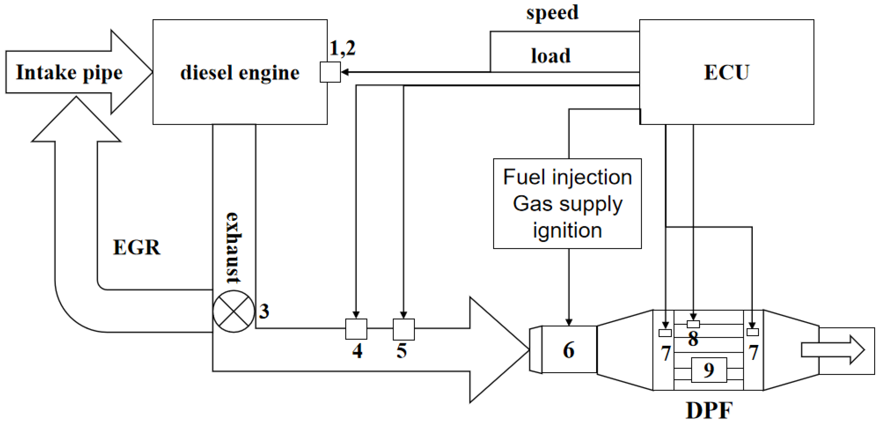
3. Model Establishment and Boundary Conditions

3.1. Geometric Modeling and Meshing

The diesel particulate filter (DPF) is made of silicon carbide, and the specific structure and physical characteristics are shown in Table 1.

3.2. Grid Independence

Generally, the DPF is divided into five parts: inlet tube, inlet cone, porous medium filter (core part), outlet cone, and outlet tube. The schematic diagram of the DPF structure is depicted in Figure 2a. The porous media filter of the DPF consists of a series of inlet and outlet channels, which are blocked alternately. The exhaust gas flows into the adjacent outlet channel through the porous media wall due to the blockage at the end of inlet channels after diesel exhaust flow from inlet channels into the filter. Meanwhile, the soot is trapped and deposited on the filter wall in the inlet channel, and the cleaned exhaust gas is discharged from the exhaust pipe into the atmosphere. Through regeneration, the accumulated soot is oxidation.
Since the influence of the grid size on the numerical results and the computation time is very sensitive, it is necessary to study the influence of the grid size on the computation results. Therefore, the grid independence of the combustion chamber geometry model of a diesel engine is studied in this work. The hexahedral grids are used to partition the volume grids of models in DPF. FIRE ESE Diesel generated geometric models with three different mesh sizes (1.5 mm, 2 mm, and 2.5 mm), as shown in Figure 2b. It can be clearly seen from Figure 2b that the number of mesh elements in the mesh model gradually decreases while the axial and radial mesh sizes gradually increase.
The process of DPF is simulated by the software of AVL FIRE. It can be seen from Figure 3 that the pressure drop of different mesh sizes reaches a peak at the same time. There is a small difference in the pressure drop. The results show that it is reasonable and reliable to use a 2 mm grid to solve the model under the balance of calculation accuracy and time.

3.3. Model Verification

Figure 4 shows a comparison of the measured values with the calculated pressure drop values. The calculated results are in good agreement with the test values. The error is mainly due to the fact that some real collisions and wear are not taken into account in the experiment. The average relative error of the numerical model is less than 5%, which indicates that the 3D engine model, initial conditions, and boundary conditions constructed in this study are good. The setting is more accurate and can meet the requirements of DPF simulation calculation. The numerical model is reliable and reasonable.

3.4. Model Selection and Setting

The whole model includes an exhaust pipe and filter body. The left side of the model is the exhaust inlet, and the right side is the exhaust outlet. Simulation analysis for different temperatures, soot loads, exhaust mass flow rates, channel densities, ratios of inlet and outlet channel, and the ratio of the length and diameter are investigated under burner-type regeneration according to the simulation cases, as shown in Table 2. The whole simulation process is 300 s, the regeneration starts at the moment of 50 s, and the exhaust temperature rises from 500 K to the specified temperature at the moment of 100 s.

4. Simulation Results and Analysis

4.1. Effect of Temperature on Soot Distribution

By simulating the cell density of 200 cpsi, a soot load of 0.2 g/L, an exhaust mass flow rate of 0.063 kg/s, and different temperatures (700 K, 750 K, 800 K, 850 K, 900 K, and 950 K), the simulation was carried out. The influence curve of the soot mass concentration is shown in Figure 5. When the temperature is 700 K (427 °C), the mass concentration of soot increases linearly without regeneration. When the temperature was 750 K (477 °C), the carbon smoke began to regenerate, and the mass concentration of the soot decreased. When the temperature was 850 K, the mass concentration of the regenerated soot was low, which was controlled below 0.25 g/L. When the temperature was 900 K, the mass concentration of the soot was close to 0 g/L. The mass concentration of the soot first reached its maximum when the temperature was between 800 K and 950 K. As the temperature increases, the maximum value gradually decreases, and the maximum time isreached earlier. Finally, the mass concentration of the soot is also low after regeneration.
As shown in Figure 6, the soot thickness of the burner-type DPF generally increases linearly. As the position of the channel moves backward, the thickness of the soot increases. With the increase in temperature, the thickness of the soot decreases, and the rise rate decreases. When the regeneration temperature of soot is 850 K, the maximum ash thickness is controlled below 0.01 mm. It has little effect on the soot capture of DPF, and 850 K is the appropriate regeneration temperature.

4.2. Effect of Exhaust Mass Flow on Soot Distribution

By simulating a channel density of 200 cpsi, a soot load of 0.2 g/L, a temperature of 850 K, and different exhaust mass flow rates (0.033 kg/s, 0.048 kg/s, 0.063 kg/s, 0.078 kg/s, 0.093 kg/s, and 0.108 kg/s), the soot concentration curves are shown in Figure 7. The changing trend of the soot concentration curve with time is similar to that of the temperature above 850 K, which first reaches a maximum and then decreases to a lower concentration. With the increase in exhaust mass flow rate, the mass concentration of soot increases. The rise rate increases and the maximum value is reached earlier. With the increase in the exhaust mass flow rate, the amount of soot entering the DPF increases correspondingly.
As shown in Figure 8, the soot thickness of the burner-type regenerative DPF increases linearly. The dimensionless position of the channel is the ratio of the distance between a point and the beginning of the channel to the channel length. The longer the channel position, the greater the soot thickness. With the increase in the exhaust mass flow rate, the thickness of soot increases, and the rising rate increases. When the exhaust mass flow rate is 0.093 kg/s, the thickness of soot reaches the maximum. When the exhaust mass flow rate is 0.063 kg/s and 0.078 kg/s, the rising rate is faster, and the soot thickness at the tail of DPF increases. When the exhaust mass is 0.093 kg/s and 0.108 kg/s, the rise rate is more uniform. Because the exhaust mass flow rate is large, the flow rate is fast, and soot accumulation at the tail is less.
As shown in Figure 9, since the exhaust gas has just entered the DPF, the burst-type regeneration of DPF starts after 50 s. The flow uniformity is relatively turbulent in 0–50 s and very turbulent in 50–150 s. After 150 s, the overall flow uniformity of DPF is relatively stable. As the exhaust mass flow rate increases, the early flow uniformity becomes more turbulent. After stabilization, the flow uniformity becomes worse.

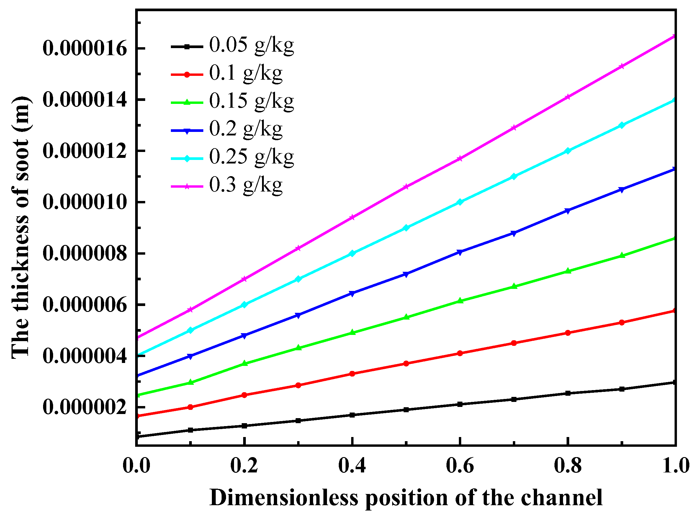
4.3. Effect of Soot Loading on Soot Distribution

Cases under the channel density of 200 cpsi, the exhaust temperature of 850 K, the exhaust mass flow rate of 0.063 kg/s, and different soot loads (0.05 g/L, 0.1 g/L, 0.15 g/L, 0.2 g/L, 0.25 g/L, and 0.3 g/L) are simulated, as shown in Figure 10. The changing trend of the soot mass concentration curve with time is similar to that of different exhaust mass flow rates. It first reaches a maximum and then decreases to a lower concentration. The mass concentration of the soot increased with the increase in soot load. The rate of ascent increases. The maximum reached increases. The mass concentration of the soot increased after regeneration. As shown in Figure 11, the soot thickness of burner-type regeneration DPF increases linearly. With the lower position of the channel, the soot thickness increased. With increased soot load, the soot thickness increases, and the rising rate increases.

4.4. Effect of Channel Density on Soot Distribution

The soot loading and regeneration process of DPF are shown in Figure 12 by simulating different channel densities (100, 150, 200, 250, 300, and 350 cpsi) with an exhaust mass flow rate of 0.063 kg/s, a soot load of 0.2 g/L, and a temperature of 850 K. The changing trend of the soot concentration curve with time is similar to that of the temperature above 850 K, which first reaches a maximum and then decreases to a lower concentration. The change of channel density has little effect on the mass concentration of the soot. The mass concentration of the soot increased with increasing channel density, the rate of ascent increased, and the maximum value increased. After regeneration, the mass concentration of the soot increased, and the final mass concentration of the soot was close to 0.2 g/L.
When the filter volume is constant, the channel density increases, and the number of channels increases, leading to the increase in soot mass concentration. In the actual production process, it is difficult to process when the channel density is too large, resulting in an increased pressure drop. These factors should be considered when choosing the channel density.
As shown in Figure 13, the soot thickness of the burner-type regeneration DPF increases linearly. As the position of the channel moves backward, the soot thickness increases. With the increase in channel density, the thickness and rising rate of soot decrease. When the channel density is more than 250, the change in soot thickness is basically the same. When the exhaust mass flow rate and soot load are constant, the channel density increases, and the amount of soot entering a single channel decreases. The ash thickness decreases with the increase in channel density.

4.5. Effect of the Ratio of Inlet and Outlet Channel on the Distribution of Soot

The influence curves of the soot mass concentration under different ratios of inlet and outlet channels (1, 1.1, 1.2, 1.3, 1.4, 1.5) with a channel density of 200 cpsi, an exhaust mass flow rate of 0.063 kg/s, a soot load of 0.2 g/kg, and a temperature of 850 K are simulated, as shown in Figure 14. The changing trend of the soot concentration curve with time is similar to that of different channel densities. It first reaches a maximum and then decreases to a lower concentration. The final soot concentration was close to 0.2 g/L. The change in the proportion of inlet and outlet channels has little effect on the mass concentration of soot. It can be concluded that the proportion of inlet and outlet channels has no effect on the soot concentration.
As shown in Figure 15, the soot thickness of the burner-type regeneration DPF increases linearly. The ratio of the inlet and outlet channels is the ratio of the inlet channel diameter to the outlet channel diameter. The longer the channel position, the greater the thickness of the soot. The soot thickness and rising rate decrease with the increase in the proportion of inlet and outlet channels. When the ratio of inlet and outlet channels exceeds 1.3, the change of thickness of soot is basically the same. An increase in the ratio of inlet and outlet channels results in an increase in inlet channel diameter. It makes it easier for the exhaust gas to flow axially, resulting in increased soot thickness at the tail of the DPF.

4.6. Effect of Aspect Ratio on Soot Distribution

By simulating the soot loading and regeneration process with a channel density of 200 cpsi, an exhaust mass flow of 0.063 kg/s, a soot load of 0.2 g/kg, and an exhaust temperature of 850 K, the influence curve of different ratios of filter length to filter diameter (0.6, 0.9, 1.2, 1.5, 1.8, 2.1) on the mass concentration of soot is shown in Figure 16. The specific parameters of the ratio of filter length to filter diameter (length–diameter ratio) are shown in Table 3 when the volume of the filter is kept unchanged.
The changing trend of the soot concentration curve with time is similar to that of different channel densities. It first reaches a maximum value and then decreases to a lower concentration. The mass concentration of regenerated soot is close to 0.2 g/L. The change in the length–diameter ratio has little effect on soot mass concentration, so it can be considered that the length–diameter ratio has no effect on the mass concentration of soot. As shown in Figure 17, the soot thickness of the burner-type regeneration DPF increases linearly. With the lower position of the channel, the soot thickness increases. In addition to the length–diameter ratio of 2.1, the soot thickness and the rising rate increase with the increase in the length–diameter ratio. Under the condition that the filter volume is kept constant, the long channel will reduce the thickness of soot when the length–diameter ratio is 2.1.

5. Conclusions

Using AVL FIRE to simulate and analyze burner-type regenerative DPF, the major conclusions are summarized as follows:
(1)
The soot distribution characteristics of burner-type regenerative DPF: the soot mass concentration first rises rapidly to the maximum value. The burner-type regeneration begins to decrease rapidly to lower values. Soot thickness increased gradually with increasing of the channel location.
(2)
With the increase in exhaust mass flow rate and soot load, the mass concentration of soot and the thickness of soot increase. The soot concentration and thickness decreased with the increase in temperature. When the temperature exceeds 750 K, the mass concentration and thickness of soot decrease, and the soot begins to regenerate. Among the exhaust parameters, the exhaust mass flow rate has the greatest influence on the soot distribution, which is due to the large change in flow uniformity due to the change in flow velocity.
(3)
The ratio of the filter length to filter diameter, the ratio of the inlet and outlet channels, and the channel densities have little effect on the mass concentration of soot. The soot mass concentration increases with the increase in the channel density. In addition to the length–diameter ratio of 2.1, soot thickness and rising rate increase with the increase in the ratio of filter length to filter diameter. With the increase in channel density and the ratio of the inlet and outlet channels, the soot thickness decreases. Among the structural parameters, the channel density has the greatest influence on the soot distribution.

Author Contributions

Conceptualization, G.J.; methodology, H.Z.; investigation, G.T. and H.Z.; data curation, C.Z. and B.Z.; writing—original draft preparation, G.T.; writing—review and editing, G.J.; supervision, C.Z. and B.Z.; project administration, G.J.; funding acquisition, G.J. All authors have read and agreed to the published version of the manuscript.

Funding

This work is supported by Natural Science Foundation of Hunan Province (grant number 2022JJ50041); Scientific Research Foundation of Hunan Provincial Education Department (grant number 17B278).

Institutional Review Board Statement

Not applicable.

Informed Consent Statement

Not applicable.

Data Availability Statement

The data presented in this study are available in the main text of the article.

Conflicts of Interest

The authors declare that they have no conflict of interests regarding the publication of this study.

References

  1. Kontses, A.; Dimaratos, A.; Keramidas, C.; Williams, R.; Hamje, H.; Ntziachristos, L.; Samaras, Z. Effects of fuel properties on particulate emissions of diesel cars equipped with diesel particulate filters. Fuel 2019, 255, 115879. [Google Scholar] [CrossRef]
  2. Zuo, Q.; Tang, Y.; Chen, W.; Zhang, J.; Shi, L.; Xie, Y. Effects of exhaust parameters on gasoline soot regeneration performance of a catalytic gasoline particulate filter in equilibrium state. Fuel 2020, 265, 117001. [Google Scholar] [CrossRef]
  3. Deng, Y.; Liu, H.; Zhao, X.; Jiaqiang, E.; Chen, J. Effects of cold start control strategy on cold start performance of the diesel engine based on a comprehensive preheat diesel engine model. Appl. Energy 2018, 210, 279–287. [Google Scholar] [CrossRef]
  4. Zuo, Q.; Xie, Y.; Guan, Q.; Zhu, G.; Jiaqiang, E.; Zhu, X.; Tang, Y.; Wang, Z.; Chen, W. Effect of critical dual-carrier structure parameters on performance enhancement of a dual-carrier catalytic converter and the gasoline engine system. Energy Convers. Manag. 2020, 204, 112325. [Google Scholar] [CrossRef]
  5. Zhang, B.; Li, X.W.; Zuo, Q.S.; Yi, Z.B.; Zhang, J.P.; Chen, W.; Lu, C.; Tan, D.L. Effects analysis on hydrocarbon light-off performance of a catalytic gasoline particulate filter during cold start. Environ. Sci. Pollut. Control. Ser. 2022. [Google Scholar] [CrossRef] [PubMed]
  6. Walter, R.; Neumann, J.; Hinrichsen, O. Modeling the catalytic performance of coated gasoline particulate filters under various operating conditions. Ind. Eng. Chem. Res. 2021, 60, 16993–17005. [Google Scholar] [CrossRef]
  7. Zhang, Z.; Li, J.; Tian, J.; Xie, G.; Tan, D.; Qin, B.; Huang, Y.; Cui, S. Effects of different diesel-ethanol dual fuel ratio on performance and emission characteristics of diesel engine. Processes 2021, 9, 1135. [Google Scholar] [CrossRef]
  8. Zhang, Z.; Tian, J.; Li, J.; Ji, H.; Tan, D.; Luo, J.; Jiang, Y.; Yang, D.; Cui, S. Effects of different mixture ratios of methanol-diesel on the performance enhancement and emission reduction for a diesel engine. Processes 2021, 9, 1366. [Google Scholar] [CrossRef]
  9. Zhang, B.; Li, X.W.; Wan, Q.; Liu, B.; Jia, G.H.; Yi, Z.B. Hydrocarbon emission control of an adsorptive catalytic gasoline particulate filter during cold-start period of the gasoline engine. Energy 2023, 262, 125445. [Google Scholar] [CrossRef]
  10. Chen, S.; Tian, J.; Li, J.; Li, W.; Zhang, Z. Investigation of the performance and emission characteristics of a diesel engine with different diesel-methanol dual-fuel ratios. Processes 2021, 9, 1944. [Google Scholar] [CrossRef]
  11. Li, Y.; Chen, Y.; Wu, G.; Liu, J. Experimental evaluation of water-containing isopropanol-n-butanol-ethanol and gasoline blend as a fuel candidate in spark-ignition engine. Appl. Energy 2018, 219, 42–52. [Google Scholar] [CrossRef]
  12. Millo, F.; Rafigh, M.; Andreata, M.; Vlachos, T.; Arya, P.; Miceli, P. Impact of high sulfur fuel and de-sulfation process on a close coupled diesel oxidation catalyst and diesel particulate filter. Fuel 2017, 198, 58–67. [Google Scholar] [CrossRef]
  13. Wang, Z.; Li, L. Effect of pre-injection on combustion and emission characteristics of a diesel engine fueled with diesel/methanol/n-butanol blended fuel. Processes 2022, 10, 60. [Google Scholar] [CrossRef]
  14. Feng, R.; Chen, K.; Sun, Z.; Hu, X.; Li, G.; Wang, S.; Deng, B.; Sun, W. A comparative study on the energy flow of a hybrid heavy truck between AMT and MT shift mode under local driving test cycle. Energy Convers. Manag. 2022, 256, 115359. [Google Scholar] [CrossRef]
  15. Jia, G.; Tian, G.; Zhang, D. Effects of plateau environment on combustion and emission characteristics of a plateau high-pressure common rail diesel engine with different blending ratios of biodiesel. Energies 2022, 15, 550. [Google Scholar] [CrossRef]
  16. Smyk, E.; Markowicz, M. Acoustic and flow aspects of synthetic jet actuators with chevron orifices. Appl. Sci. 2021, 11, 652. [Google Scholar] [CrossRef]
  17. Smyk, E.; Gil, P.; Gałek, R.; Przeszłowski, Ł. Acoustic and flow aspects of novel synthetic jet actuator. Actuators 2020, 9, 100. [Google Scholar] [CrossRef]
  18. Gil, P.; Smyk, E.; Gałek, R.; Przeszłowski, Ł. Thermal, flow and acoustic characteristics of the heat sink integrated inside the synthetic jet actuator cavity. Int. J. Therm. Sci. 2021, 170, 107171. [Google Scholar] [CrossRef]
  19. Jiaqiang, E.; Zhao, X.; Xie, L.; Zhang, B.; Chen, J.; Zuo, Q.; Han, D.; Hu, W.; Zhang, Z. Performance enhancement of microwave assisted regeneration in a wall-flow diesel particulate filter based on field synergy theory. Energy 2019, 169, 719–729. [Google Scholar] [CrossRef]
  20. Williams, A.M.; Garner, C.P.; Binner, J.G.P. Analysis and optimization of gel-cast ceramic foam diesel particulate filter performance. Proc. Inst. Mech. Eng. Part D J. Automob. Eng. 2008, 222, 2235–2247. [Google Scholar] [CrossRef]
  21. Tong, Y.; Tan, J.; Meng, Z.; Chen, Z.; Tan, L. Experimental investigation on the DPF high-temperature filtration performance under different particle loadings and particle deposition distributions. Processes 2021, 9, 1465. [Google Scholar] [CrossRef]
  22. Zhang, B.; Jiaqiang, E.; Gong, J.; Yuan, W.; Zhao, X.; Hu, W. Influence of structural and operating factors on performance degradation of the diesel particulate filter based on composite regeneration. Appl. Therm. Eng. 2017, 121, 838–852. [Google Scholar] [CrossRef]
  23. Wu, G.; Tang, K.; Wu, D.; Li, Y.; Li, Y. Experimental evaluation on the catalytic activity of a novel CeZrK/rGO nanocomposite for soot oxidation in catalyzed diesel particulate filter. Processes 2021, 9, 674. [Google Scholar] [CrossRef]
  24. Zhang, Z.; Ye, J.; Tan, D.; Feng, Z.; Luo, J.; Tan, Y.; Huang, Y. The effects of Fe2O3 based DOC and SCR catalyst on the combustion and emission characteristics of a diesel engine fueled with biodiesel. Fuel 2021, 290, 120039. [Google Scholar] [CrossRef]
  25. Ye, J.; Lv, J.; Tan, D.; Ai, Z.; Feng, Z. Numerical analysis on enhancing spray performance of SCR mixer device and heat transfer performance based on field synergy principle. Processes 2021, 9, 786. [Google Scholar] [CrossRef]
  26. Zhong, C.; Gong, J.; Wang, S.; Tan, J.; Liu, J.; Zhu, Y.; Jia, G. NO2 catalytic formation, consumption, and efflux in various types of diesel particulate filter. Environ. Sci. Pollut. Res. 2021, 28, 20034–20044. [Google Scholar] [CrossRef]
  27. Liu, G.; Liu, W.; He, Y.; Gong, J.; Li, Q. Research on influence of exhaust characteristics and control strategy to DOC-assisted active regeneration of DPF. Processes 2021, 9, 1403. [Google Scholar] [CrossRef]
  28. Shi, X.; Jiang, D.; Wang, Q.; Liang, Y. Impact factors analysis of diesel particulate filter regeneration performance based on model and test. Processes 2021, 9, 1748. [Google Scholar] [CrossRef]
  29. Zhao, X.; Zuo, H.; Jia, G. Effect analysis on pressure sensitivity performance of diesel particulate filter for heavy-duty truck diesel engine by the nonlinear soot regeneration combustion pressure model. Energy 2022, 257, 124766. [Google Scholar] [CrossRef]
  30. Zhao, X.; Zuo, H.; Jia, G. Effects of the continuous pulsation regeneration on the soot combustion in diesel particulate filter for heavy-duty truck. Chemosphere 2022, 306, 135651. [Google Scholar] [CrossRef] [PubMed]
  31. Zhao, X.; Jiaqiang, E.; Liao, G.; Zhang, F.; Chen, J.; Deng, Y. Numerical simulation study on soot continuous regeneration combustion model of diesel particulate filter under exhaust gas heavy load. Fuel 2021, 290, 119795. [Google Scholar] [CrossRef]
  32. Jiaqiang, E.; Zhao, X.; Liu, G.; Zhang, B.; Zuo, Q.; Wei, K.; Li, H.; Han, D.; Gong, J. Effects analysis on optimal microwave energy consumption in the heating process of composite regeneration for the diesel particulate filter. Appl. Energy 2019, 254, 113736. [Google Scholar]
  33. Palma, V.; Ciambelli, P.; Meloni, E.; Sin, A. Catalytic DPF microwave assisted active regeneration. Fuel 2015, 140, 50–61. [Google Scholar] [CrossRef]
  34. Palma, V.; Meloni, E. Microwave assisted regeneration of a catalytic diesel soot trap. Fuel 2016, 181, 421–429. [Google Scholar] [CrossRef]
  35. Lee, S.; Jeong, S.; Kim, W. Numerical design of the diesel particulate filter for optimum thermal performances during regeneration. Appl. Energy 2009, 86, 1124–1135. [Google Scholar] [CrossRef]
  36. Tsuneyoshi, K.; Yamamoto, K. Study on the cell structure and the performances of wall-flow diesel particulate filter. Energy 2012, 48, 492–499. [Google Scholar] [CrossRef]
  37. Rodríguez, J.; Lapuerta, M.; Sanchez, J. Regeneration of diesel particulate filters: Effect of renewable fuels. Renew. Energy 2017, 104, 30–39. [Google Scholar] [CrossRef]
  38. Smyk, E.; Mrozik, D.; Olszewski, Ł.; Peszyński, K. Numerical simulation of minor losses coefficient on the example of elbows. EPJ Web Conf. 2018, 180, 02093. [Google Scholar] [CrossRef]
  39. Smyk, E. Numerical simulation of axisymmetric valve operation for different outer cone angle. EPJ Web Conf. 2017, 143, 02112. [Google Scholar] [CrossRef] [Green Version]
  40. Fu, J.; Tang, Y.; Li, J.X.; Ma, Y.; Chen, W.; Li, H. Four kinds of the two-equation turbulence model’s research on flow field simulation performance of DPF’s porous media and swirl-type regeneration burner. Appl. Therm. Eng. 2016, 93, 397–404. [Google Scholar] [CrossRef]
  41. Konstandopoulos, A.G.; Kostoglou, M.; Lorentzou, S.; Vlachos, N. Aspects of multifunctional diesel particulate filters and their efficient simulation. Catal. Today 2012, 188, 2–13. [Google Scholar] [CrossRef]
  42. Lupse, J.; Campolo, M.; Soldati, A. Modelling soot deposition and monolith regeneration for optimal design of automotive DPFs. Chem. Eng. Sci. 2016, 151, 36–50. [Google Scholar] [CrossRef]
  43. Serrano, J.R.; Arnau, F.J.; Piqueras, P.; Garcia-Afonso, O. Packed bed of spherical particles approach for pressure drop prediction in wall-flow DPFs (diesel particulate filters) under soot loading conditions. Energy 2013, 58, 644–654. [Google Scholar] [CrossRef]
Figure 1. Schematic diagram of the composition of burner-type regeneration DPF system. (1, speed sensor; 2, torque meter; 3, EGR valve; 4, flow sensors; 5, oxygen concentration sensor; 6, fuel injection burner; 7, pressure sensor; 8, temperature sensor; 9, filter body).
Processes 10 02029 g001
Figure 2. Geometric model and grid model of the DPF. (a) DPF geometric model; (b) Three different size grid models.
Processes 10 02029 g002
Figure 3. Pressure drop curves of different grid sizes.
Processes 10 02029 g003
Figure 4. Comparison of test value and simulation value of pressure drop.
Processes 10 02029 g004
Figure 5. The influence of different temperatures on the mass fraction of soot.
Processes 10 02029 g005
Figure 6. The influence of different temperatures on thickness of soot.
Processes 10 02029 g006
Figure 7. The influence of different exhaust mass flow rate on the mass fraction of soot.
Processes 10 02029 g007
Figure 8. The influence of different exhaust mass flow rate on the thickness of soot.
Processes 10 02029 g008
Figure 9. The influence of different exhaust mass flow rate on flow uniformity.
Processes 10 02029 g009
Figure 10. The influence of different soot load on the mass fraction of soot.
Processes 10 02029 g010
Figure 11. The influence of different soot load on the thickness of soot.
Processes 10 02029 g011
Figure 12. The influence of different channel density on the mass fraction of soot.
Processes 10 02029 g012
Figure 13. The influence of different channel density on the thickness of soot.
Processes 10 02029 g013
Figure 14. The influence of different ratio of inlet and outlet channels on the mass fraction of soot.
Processes 10 02029 g014
Figure 15. The influence of the ratio of different inlet and outlet channels on the thickness of soot.
Processes 10 02029 g015
Figure 16. The influence of different length–diameter ratios on the mass fraction of soot.
Processes 10 02029 g016
Figure 17. The influence of different length–diameter ratios on the thickness of soot.
Processes 10 02029 g017
Table 1. DPF parameters.
ParametersNumerical Value
Filter sizeФ120 mm × 180 mm
Channel diameter1.397 mm
density1500 kg/m3
Specific heat capacity1250 J/kg · K
Thermal Conductivity5 W/m · K
Wall thickness0.39 mm
Intake and exhaust pipe diameter60 mm
Permeability of soot filter cake layer5 × 10−15 m2
Channel wall permeability1 × 10−13 m2
Table 2. Simulation cases of the burner type regeneration DPF.
SchemesParametersCases
1Cell density (cpsi)200
Soot load (g/L)0.2
Exhaust mass flow rate (kg/s)0.063
Exhaust temperature (K)700, 750, 800, 850, 900, 950
2Cell density (cpsi)200
Soot load (g/L)0.2
Exhaust temperature (K)850
Exhaust mass flow rate (kg/s)0.033, 0.048, 0.063, 0.078, 0.093, 0.108
3Cell density (cpsi)200
Exhaust mass flow rate (kg/s)0.063
Exhaust temperature (K)850
Soot load (g/L)0.05, 0.1, 0.15, 0.2, 0.25, 0.3
4Exhaust mass flow rate (kg/s)0.063
Exhaust temperature (K)850
Soot load (g/L)0.2
Cell density (cpsi)100, 150, 200, 250, 300, 350
5Exhaust mass flow rate (kg/s)0.063
Exhaust temperature (K)850
Soot load (g/L)0.2
Cell density (cpsi)200
Ratio of inlet and outlet channels1, 1.1, 1.2, 1.3, 1.4, 1.5
6Exhaust mass flow rate (kg/s)0.063
Exhaust temperature (K)850
Soot load (g/L)0.2
Cell density (cpsi)200
Ratio of length and diameter0.6, 0.9, 1.2, 1.5, 1.8, 2.1
Table 3. The ratio of filter length to filter diameter.
ParametersValues
Ratio0.60.91.21.51.82.1
Length/mm97.8127.8154.8180203.4224.7
Diameter/mm163142129120113107
Publisher’s Note: MDPI stays neutral with regard to jurisdictional claims in published maps and institutional affiliations.

