Article

Deionized Water Electrochemical Machining Hybridized with Alumina Powder Polishing for Microcavity of M-333 Mold Steel

by
Albert Wen-Jeng Hsue
* and
Zih-Yuan Huang
Department of Mold and Die Engineering, National Kaohsiung University of Science and Technology, No. 415 Jiangong Road, Sanming District, Kaohsiung 80778, Taiwan
*
Author to whom correspondence should be addressed.
Processes 2022, 10(1), 152; https://doi.org/10.3390/pr10010152
Submission received: 3 October 2021 / Revised: 21 December 2021 / Accepted: 27 December 2021 / Published: 13 January 2022
(This article belongs to the Special Issue New Frontiers in Magnetic Polishing and Electrochemical Technology)

Abstract

:
An electrochemical machining (ECM) process for microcavity fabrication with deionized water (DI-water) and an ECM polishing hybrid with alumina powder of 1.0 μm grains on a single micro-EDM machine are proposed. The process adopts tungsten carbide as tool electrode and M-333 tool steel as the mold material. It reveals that employing the 30 μm/min feed rate with 50 mA and 0.2 ms of pulse-width is suitable for DI-water electrochemical machining. The DI-water ECM process can achieve an excellent surface roughness at Ra 0.169 µm on a semispherical round cavity. Combining the ECM with hybrid polishing with the alumina powder can achieve a better profile for a much deeper cavity than pure electrolytic discharge machining. The hybrid ECM polishing can efficiently finish a micro square insert of 0.6 mm length at 64 μm depth. Such ECM milling can achieve an S-shaped microchannel of radius 1.0 mm and a slot of 1.0 × 0.5 mm2 with 110 μm depth, demonstrating its feasibility and the surface integrity with accurate profile and roughness of Ra 0.227 μm. This study provides a cost-effective scheme for micro mold fabrication with a conventional micro-EDM machine tool and an intuitive and convenient optional process. However, some micro-electrical discharges occurred due to the breakdown of insulation, which creates micro craters on the surface of the parts.

1. Introduction

Based on physical and chemical principles, various nontraditional machining processes, such as electrical discharge machining (EDM) and electrochemical machining (ECM), have been well developed and play active roles in precision production and microfabrication technology fields. However, besides the inaccurate contour caused by tool wear problems, the machined surface by EDM remains a heat-affected zone, with recast layers, and even micro craters. There are still many complex works required to improve the EDM process. Especially, hybrid processes combining EDM with the other physical or chemical processes are emerging in the industrial fields.
ECM is very good at removing the tiny bits from the work surface on the scale of atom size, based on the anodic dissolution action. With the absence of residual mechanical stress, heat damages, and tool wear, its advantages are desirable to manufacturing engineers. However, the drawbacks are the expensive ECM cost with detailed feasibility and high current-density requirement and nonenvironmentally friendly chemical solution and toxin wasters. Nevertheless, the advantages of both the EDM and ECM involve generating complicated features or structures regardless of their mechanical properties. Moreover, they can quickly be implemented to meet the requirement of miniature scale.
Studies on deionized water ECM milling were rarely seen in the past decades. However, in recent years, Nguyen et al. [1] proposed a scheme of micro-ECM milling in low-resistivity deionized water and analyzed the transitions of micro-EDM to sequential electrical discharge chemical machining (SEDCM). Li et al. [2] proposed micro-ECM with the edge of tool in their study on localized ECM micromachining (EMM) with gap control. A microcavity of 400 μm square and 200 μm depth was successfully demonstrated. Choi et al. [3] proposed an analysis of tungsten carbide electrodes in the micro-ECM process, and with a feed rate of 1 μm/sec milling depth of 2 µm/layer; they demonstrated a micro slot of 60 µm square and many microcavities.
Yan et al. [4] presented the hybrid processing of EDM with alumina (Al2O3) powder into the EDM oil for the surface polishing of SKD-11 tool steel. They revealed that electrophoresis of alumina particles within EDM oil could smooth the surge profile of the EDM surface.
Furutani et al. [5] designed a particular device assembled with a pair of copper electrodes spaced at intervals of 1 mm to observe the electrophoresis of various particles. They reported three primary morphologies, i.e., the longer chain between both electrodes for Ti particles, adhered to the cathode for alumina particles, and reciprocation movement between both electrodes for tungsten carbide and TiC particles.
On the other hand, Yan et al. [6] proposed a sequential polishing with alumina powder in HCl solution after EDM. The alumina particles, which usually have some electrical charge in the electrolyte, were adhered to the tool’s surface with electrophoretic deposition and used to finish the electro-discharge machined surface. According to the report, by conducting with 0.30 µm of particle grits, the work surface can be polished from 0.52 µm Ra to 68 nm in 10 min.
Recent development reveals that the microelectrochemical discharge process (micro-ECDM) can produce miniature three-dimensional parts or structures in the micro- or even nanoscale. It is usually conducted with relatively low current requirements and produces only a few wastes. This reveals many possibilities for a cluster of new microfabrication applications. Therefore, developing a hybrid process that combines the electrochemical discharge processes with polishing with powder suspending in the dielectric fluid seems promising to meet the industrial requirement.
For example, in a review paper, Kumar et al. made a comparison between μ-EDM, μ-ECM, and μ-ECDM for industrial and research use [7]. They point out that at least micro-ECM and micro-ECDM are superior to micro-EDM on both the higher MRR (removal rate) and the more refined surface finish and more minor thermal-induced defects (such as HAZ, recast layers, and microcracks). It is emerging to introduce ECM and micro-ECM to the microcavity in mold industries and precise biomedical and aerospace parts fabrication.
In 2008, a report adopted an ECM in pure water process (PW-ECM) for aerospace application on the principles of water dissociation [8]. These tests explain the need for technological conditions, and trilateral and square cavities and holes and a group of English alphabets are worked out on a stainless steel plate. It is confirmed that PW-ECM will probably be an efficient new aviation precision-machining method. The relationship between anode potential and current density is provided and the electrochemical characteristics of metal dissolution in well known in ECM fields [9].
An earlier report surveyed micro-ECM-related processes and their hybrid variants [10]. It outlines the research trends and engineering applications by presenting a comprehensive literature source for the first time. It also provides the related aspects of micro-tooling fabrication, advanced process capabilities, energy sources, and developing suggestions.
Yehia et al. reported in 2020 that the effect of the Al2O3 abrasive content on the metal removal rate and the Ra of the K110 steel using electrochemical grinding at different voltages, feed rates, electrolyte NaCl concentrations, and various depths of the cut were investigated [11]. The results revealed that the abrasive, electrochemical grinding was better than the electrochemical grinding results. The maximum effect of the Al2O3 on the metal removal rate was achieved at 5 wt %. The current density in the machining gap was affected by the addition of the Al2O3.
Physical principles and miniaturization of spark-assisted chemical engraving (SACE) were reported in a paper in 2005 [12]. With a particular setup based on an AFM, even using extremely sharp tools cannot produce a smaller pattern than typically 25 µm. They reveal that the main limiting factor is the gas film thickness, where the electrochemical discharges occur. In order to increase the wettability of the tool electrode and reduce the gas film thickness, it is found that the critical voltage reduces significantly, which may lead to a novel method of characterizing the gas film thickness in SACE.
A recent paper [13] demonstrates successful micromilling through microgrooves on pure commercial titanium utilizing a maskless electrochemical micromachining layer-by-layer micromilling strategy employed with the in situ fabricated disc shape microtool for milling through microgrooves. It also demonstrated the successful fabrication of a few complex geometry microgrooves by electrochemical micromilling for vital applications, such as microfluidics, microsensors, microengineering for MEMS, and biomedical systems.
Another study reports an overview of EDMM in micro- and macro-domain with recent advancement, challenges, and future scope [14]. The process phenomenon, tools, dielectric, classification, process combinations, and capabilities are presented. Various advanced techniques of optimization are discussed to improve machining performance. Tool wear is the inherent part of the process which deteriorates the workpiece surface. Compared to ECM milling, the latter is superior with no tool wear, which is especially suitable for polishing to achieve a fine surface.
In the theoretical aspect, two reports present the modeling of radial gap distance in simultaneous micro-EDM and micro-ECM drilling by predicting the thickness of the material layer [15]. Their analysis incorporates the double-layer theory, the Butler–Volmer equation and uses Faraday’s law to simulate the radial gap distance for different pulse parameters. The applied pulse parameters directly affect the final dimension of obtained microholes from observation.
Based upon the analysis of material removal in micro-EDM/ECM using deionized water, the same group of papers [1,15] reported converting removal mechanism from mere micro-EDM to hybrid micro-EDM/ECM when low feed rate is applied [16]. This observation shows that three critical factors of SEDCM, namely, low-resistivity deionized water, low feed rate, and short voltage pulses, are identified. According to the experiments, the hybrid SEDCM can improve surface finish and machining accuracy performance.
The primary purposes of this research are (1) a low-cost ECM process for microfabricating microcavity in mold industries through environmentally friendly work fluid; (2) to develop an efficient hybrid forming and polishing technology for manufacturing the precise and surface-integrity miniature mold; (3) to develop an intuitive operation and convenient optional process on a conventional micro-EDM machine tool for the industrial practice.
Considering the cost-effective, environmentally friendly, mirror-like surface requirements and the absence of tool wear for high polishing precision, this study proposes to conduct electrochemical machining of microcavities with deionized water. Hybrid ECM milling is associated with a single micro-EDM machine simultaneous hybridized alumina electrolytic polishing process, and it is also aimed at investigating suitable operational conditions.

2. Setup for ECM Milling with Deionized Water

2.1. Principle of ECDM with Deionized Water

Generally, electrochemical machining is conducted with the electrolyte or melt material. However, after dissolution in an electrochemical way, high-resistance deionized water can be adopted as an electrolyte solution [8]. As shown in Figure 1, the typical polarization curve represents the relationship between anode potential and current density and provides the electrochemical characteristics of metal dissolution in ECM [9], especially for ECM polishing. It is usually plotted as the potential versus the logarithm of the current density observed for a surface that undergoes passivation and then the breakdown on the passivation layer. The curve trend is mainly based on the combination of material and electrolyte and other influencing parameters, such as the electrode gap, electrolyte flow rate, and the characteristics of the power source. There is usually only a very narrow gap on the order of microns between both electrodes.
Each curve region can be summarized to represent electrochemical polishing status as follows. Section AB reveals the current increases due to the anodic dissolution of the workpiece, and section BC shows the current decreasing due to the passivation of the surface layer. Section CD represents the transient region with no electrical connection due to the insulating passive film; section DE shows the current rising again as the passive layer is broken down, regaining electrical contact and continuing anodic dissolution.
In section ABC, as the requirements for polishing are not formed, the anode film is still etched, and in section CD, due to the formation of demand at high current density, the anode film is polished and removed. A diffusion area dominates the anodic dissolution process along this typical curve with a stable current density. In section DE, due to the escape of gas bubbles at the anode and subsequent rupture of the anode film at a higher potential, the polishing effect is accompanied by surface pitting corrosion. However, it may be accompanied by pitting corrosion on the part’s surface. Nevertheless, section CD is chosen for better surface-polishing quality, considering minor removal with electrolytic polishing and higher processing efficiency than conventional EDM processes.
As shown in Equation (1), DI-water was first dissolved into hydrogen ions in the form of H 3 O + and hydroxide ion O H . The reaction equilibrium is maintained at a proper temperature, and then it can serve as an electrolytic solution. The equilibrium condition is achieved by obtaining a constant multiplication product of the concentration of anodic and cathodic ions and maintaining apparent voltage around the anode electrode.
2 H 2 O H 3 O + + O H
The principle of the hybrid electrolytic polishing process associated with alumina powder is to fabricate the tooltip with electrophoretic deposition and finish the machining surface simultaneously with ECM reaction. A characteristic feature of such an electrophoretic deposition process is that gluey particles, such as alumina abrasives, are suspended in a liquid solution migrate and are deposited onto the tool electrode under the influence of an electric field.

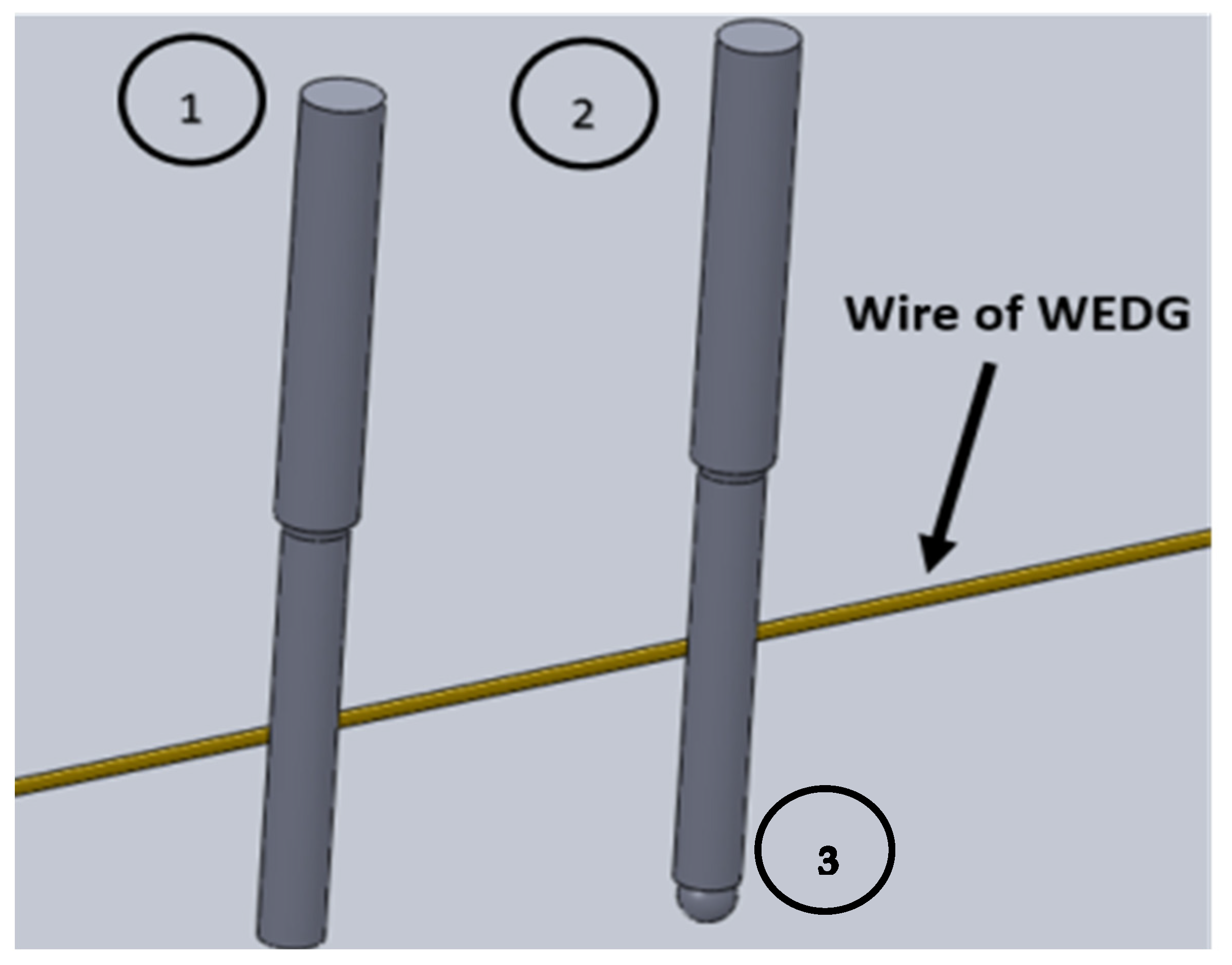
2.2. Preparation of Micro tool Electrode

A microtool of 500 µm diameter made of a tungsten carbide cylinder was dressed by a wire electrical discharge grinding process (WEDG) into 350 µm to achieve a coaxial rotation with the machine spindle. As depicted in Figure 2, such a three-step dressing process was conducted with the CNC function of the micro-EDM machine and its appended WEDG system. In the first step, the shaft was dressed with 0.5 A of current EDM at 500 rpm revolution, and then 50 mA peak current with 300 rpm was applied to finish the semispherical tool to 350 µm diameters. Then, it was cleaned with propanone and ethyl–alcohol solution in 10 min.

2.3. Design of Tooltip on Consideration of Electric Field

A cylinder tool is usually adopted in conventional micro-EDM drilling and milling. However, in this study, the micro tooltip was designed to be semispherical to maintain the uniform electric field strength around the periphery of the tooltip.
In conventional cylinder tool design, as shown in Figure 3a, there is always a clustering effect of electric flux around the edge corner. Nevertheless, as shown in Figure 3b, the tool design is based on the principle that a sphere can maintain a uniform electric field strength.

2.4. Experimental Setup

As depicted in Figure 4a, the electromachining tank is designed to be mounted on a micro-EDM machine built by a local vendor, Aristech Co, Ltd., Florence, KY, USA, The power source is a pulse-type DC power supply, retrofitting from the micro-EDM with the new circulation system in the tank. Figure 4b shows a typical pulsive waveform that reveals an open voltage of 30 VDC in channel 1 and the peak current of 50 mA in channel 2, with a time scale of 400 µs/div. The operational conditions for ECM are listed in Table 1. The M333 tool steels after vacuum heat treatment and ground processing are chosen as workpieces.
The deionized water (DI-water) serves as the electrolyte according to Equation (1), and is circulated through a small pump sunk into an ultrasonic cleaner tank; the specific resistance of deionized water is 110 kΩ-cm.
In order to improve the machining efficiency and improve the surface quality of the mold cavity, a hybrid ECM polishing method with abrasives of alumina particles is proposed. A comparative process conducts ECM with alumina powder, as a hybrid ECM polishing process, with the alumina powder added into the ECM tank. The hybrid ECM polishing is conducted with alumina powder of 1.0 µm grains. The experimental device is set up as shown in Figure 4. A sinking pump drives and makes the electrolyte circulate with mixed alumina abrasive particles. Moreover, an ultrasonic vibrator ensures the suspension of the rich-enough alumina abrasives.

3. ECM Fabrication of Microcavity

As shown in Figure 5, several preliminary tests of ECM drilling with various diameters of tooltips from 150 µm to 350 µm are investigated for microcavity, respectively. The surface roughness is measured as Ra 0.224 µm, 0.255 µm, and 0.213 µm, respectively, as shown in Figure 5a–c. Therefore, it appears that there is no significant difference in the surface roughness between these tool diameters among the investigation range. Henceforth, the microtool with 350 µm diameter is adopted in this study for quick fabrication and evaluation. Figure 5d shows the typical configuration of the spherical tooltip dressed by the WEDG system.
Moreover, conducting micro tool fabrication and ECM processes on a conventional micro-EDM machine tool is cost-effective. It will reveal a low-cost ECM process and an environment-friendly option for micro mold fabrication as it only needs some retrofit from a micro-EDM machine and preservation of the original micro-EDM function.

3.1. Operation Conditions Investigation for ECM

Figure 6 reveals the experiment’s configuration for ECM drilling and ECM milling, respectively. ECM drilling is conducted with a rotational speed of 500 rpm and starts from an initial gap height of 0.1 mm to depth of 0.01–0.02 mm with a feed rate of 30 µm/min, as stated in C-codes C1 to C3 of Table 1. The pulse energy is nearly proportional to the on-time of the pulse wave in this setup. The DC pulses, with on-times TON of 0.1–0.4 ms and a fixed off-time of 0.8 ms, are investigated. Various feed rates are also tested from 20 µm/min to 40 µm/min. Moreover, the operational conditions for the other ECM milling schemes are adjusted based on the ECM drilling results.

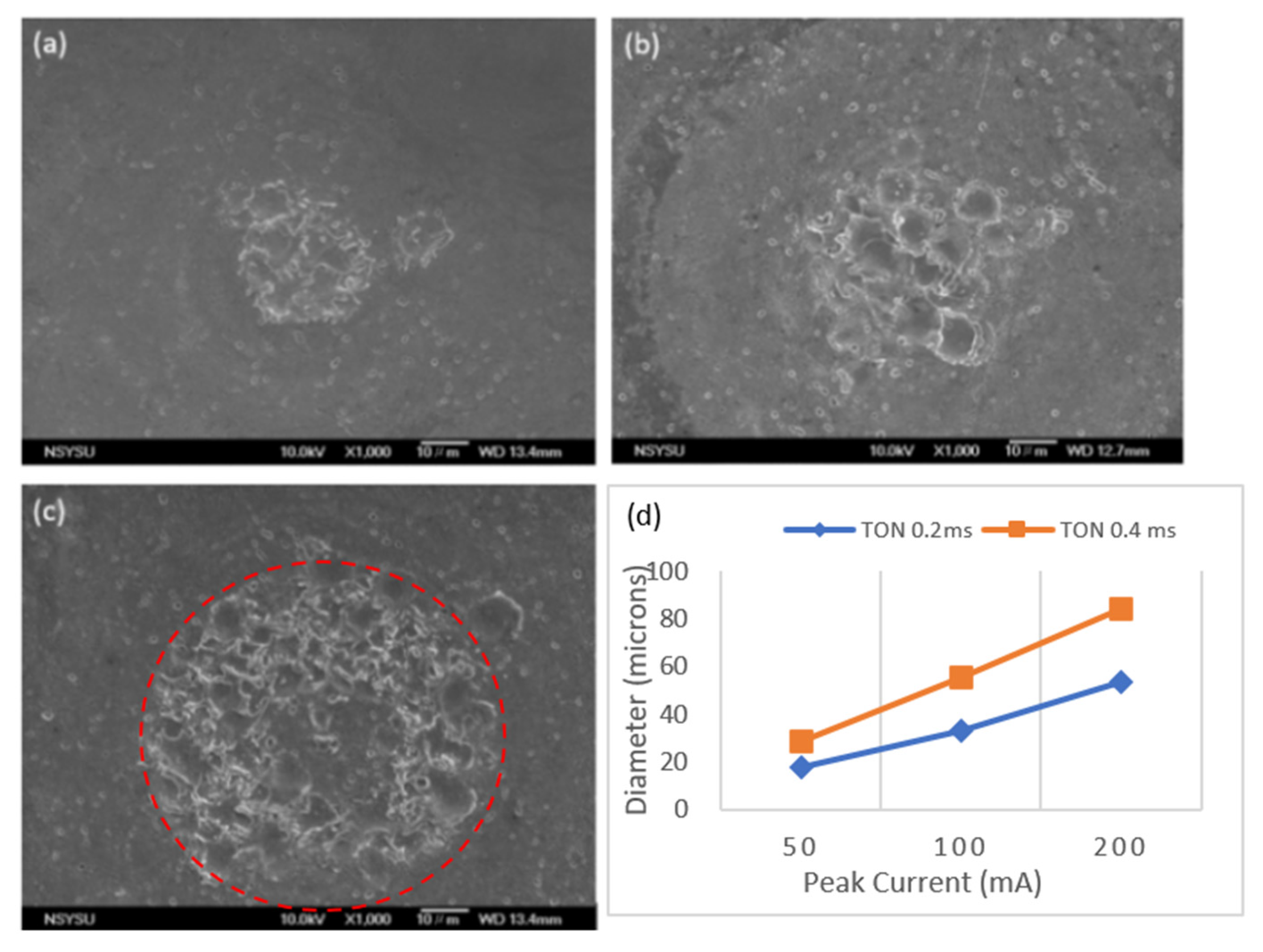
3.1.1. Effect of Peak Current on the ECM Performance

As shown in Figure 7, various DC peak currents with pulse on-time of 0.4 ms and off-time 0.8 ms were investigated for machining effect on ECM surface. A confocal LASER microscope measured the ECM drilling surface (type: Keyence VK-X200K). Figure 7a shows that lower peak current results in more miniature craters at the bottom of the cavity after ECM machining. Partial ECM and partial EDM region remain in Figure 7. Central craters were caused by EDM discharge as the spherical tooltip reached the end of the stroke because high peak current causes high electric field strength, and high resistance of DI-water tends to make the electric voltage break down in the narrow gap width.
The dash-circle in Figure 7c reveals the effective circular range for such a damaged crater by partial EDM effect. Figure 7d reveals the comparison of the effective diameter of the damaged crater circle vs. peak current, with pulse on-time of 0.2 ms and 0.4 ms. It is trivial that a higher current, such as 200 mA, tends to create a worse surface in a larger region, and a shorter on-time contributes to less area of the craters. Therefore, the suitable peak current is chosen as low as 50 mA.

3.1.2. Effect of Pulse On-Time on the ECM Performance

As shown in Figure 8, the effect of pulse on-time on the ECM performance is investigated with a peak current of 50 mA and off-time 0.8   ms , but for the processing stability, the shorter on-time 0.1 ms often causes drawback of tool electrode that cannot finish the target depth of 20 µm. Moreover, the longer on-time 0.4   ms causes severe pitting due to electroerosion outside the cavity ring, although it can reach the target depth. Therefore, TON 0.2 ms is chosen as a proper pulse on-time for ECM cavity drilling.

3.1.3. Effect of Feed Rate on the ECM Performance

Effect of feed rate is investigated with a peak current of 50 mA and the on-time of 0.2 ms with fixed off-time 0.8 ms. As shown in the microscope image of Figure 9a, the slow feed rate results in a more uniform depth but expands to the broader region. Figure 9a reveals the shallower depth and appears to have more pitting marks outside the cavity.
For Figure 9b, the medium feed rate with 30 µm/min results in a good profile with a target depth of 20 µm and less pitting erosion than Figure 9a. Although in Figure 9c, the fast feed rate of 40 µm/min can improve removal efficiency and result in minor pitting around the cavity, the profile at the central bottom is sharper than that by medium feed rate of Figure 9b. However, as shown in Figure 9d, for a longer on-time TON 0.4 ms, it results in a deeper machining depth than those with TON 0.2 ms, and even larger than the target depth. Therefore, it is proper to choose 30 µm/min as the operating condition for drilling.

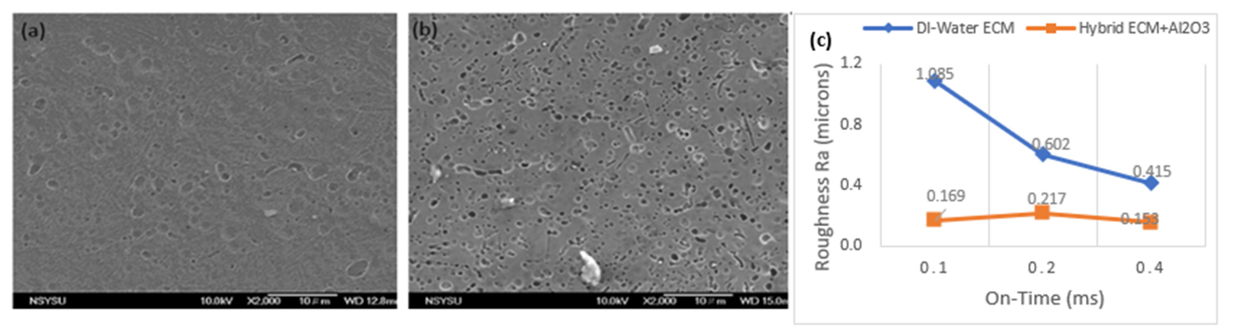
3.2. Hybrid ECM Polishing with Alumina Abrasives

In order to improve the machining efficiency and the pitting defect on the bottom surface, this paper proposes a hybrid ECM polishing with abrasives of alumina particles. The abrasive grains adopt 1.0 µm of alumina particles. The abrasives deposition is first conducted with various concentrations, as shown in Table 2. Experiments found that abrasive concentration on tooltip saturates with above 15 g/L at above 5 min of deposition time. This implies no need for denser particles or longer deposition time. Although the alumina abrasive is nonconductive, each test adopts a new DI-water solution for uniform concentration. As an alternative to the pure ECM fabrication procedure, the hybrid ECM polishing with alumina powder is conducted with the operating conditions and compared with the pure DI-water ECM as shown in Table 3.
A comparison of the hybrid alumina abrasive ECM drilling with that by pure DI-water ECM is shown in Figure 10. The cavity profile of pure DI-water ECM reveals shallower and not as much integration as hybrid alumina ECM drilling. From Figure 10b, a perfect spherical cavity of 20 µm depth is obtained with the hybrid alumina ECM polishing process, and about two to three times the machined depth compared to the original DI-water ECM in the same period.
Moreover, different roughness with the micro pits is observed in microscale images, as shown in Figure 11. The surface roughness of DI-water ECM is Ra 1.085 µm, while the hybrid alumina abrasive ECM polishing reduces it to Ra 0.169 µm. This reveals that both the profile and surface roughness of the hybrid alumina abrasive ECM are superior to those of pure DI-water ECM drilling. Figure 10 reveals a comparison of the surface roughness of ECM polishing schemes for various pulse on-times.
Figure 11 might explain the reason for the surface roughness comparison because nonconductive alumina particles result in higher resistance between the tool and work surface, which results in a smaller current under the same voltage. Moreover, the reduced gap width between both electrodes by the alumina abrasives may cause repetitive drawbacks of the tool. Therefore, the more micro pit for smaller current density remained under several repetitive approaches of the tooltip. As a result, although the hybrid ECM polishing profile is much better for its abrasive effect, from Figure 10, its micro pit erosion remains much poorer in the microscale than that of DI-water ECM. It is well known that some microscale roughness may cause a severe problem in the injection molding process. Therefore, there is a trade-off between the surface profile and the surface pitting from a microscale view.

4. ECM Micromilling

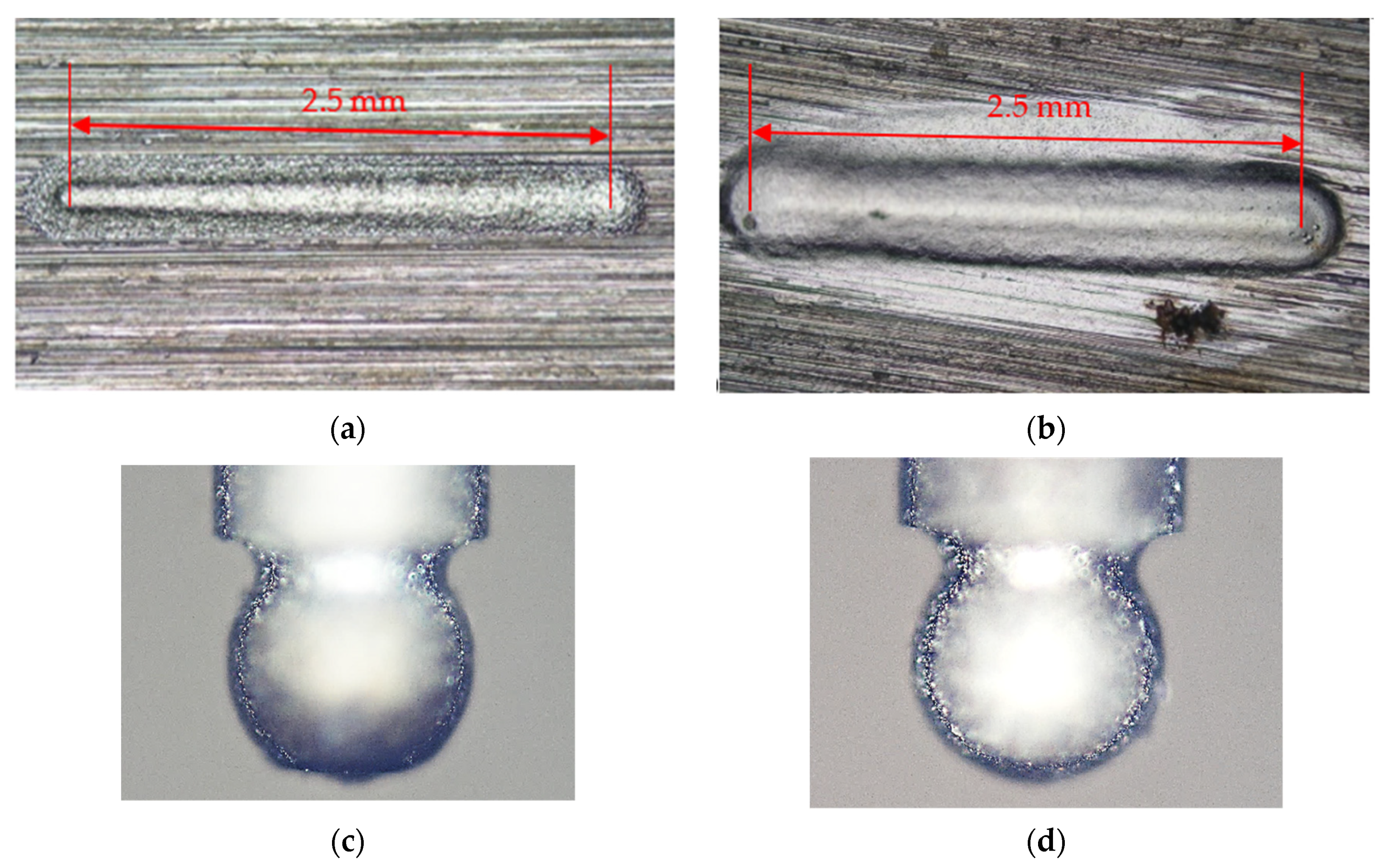
4.1. Slot Milling with Deionized Water

Based on the ECM drilling of the microcavity, proper conditions of peak current 50 mA, associated with on-time 0.2 ms and feed rate 30 µm/min, achieve the best ECM profile among the surveying range. It is further expected that performing ECM milling will achieve a qualified surface finishing and the required contour. Similar to the DI-water ECM drilling, the tool electrode adopted tungsten carbide with a spherical tooltip of Φ350 µm and set the target slot depth to 10 µm. The operation conditions for slot milling with deionized water are listed in Table 4.
The ECM milling slots are shown in Figure 12, with a feed rate from 10 ,   30 , to 60 μ m/min. The slotted profile is expanded around the starting and ending points because of the more extended staying period of the tool electrode, and therefore, Figure 12a,d reveals more electrical removal with a slow feed rate at two ends of the slot, but not uniform removal depth along the path. Figure 12c reveals that the machined depth obtains a shallower depth toward the right end of the milling path, while, as shown in Figure 12b, its profile reveals much better integrity and uniform depth under 30 µm/min of feed rate.
A typical profile is compared along the virtual central line at the bottom of the slots. Figure 13a,b reveal the centerline measurement of profiles by 30 µm/min and 60 µm/min, respectively. In addition to the much better integrity and uniform depth achieved by 30 µm/min, the surface roughness of Ra 0.13 µm revealed in Figure 13a is also better than that of Ra 0.21 µm of Figure 13b. It implies an equilibrium between the removal rate and the table feed rate appearing around the medium speed of 30 µm/min. Some slightly deeper slots are measured in Figure 13a. Some much deeper erosion occurred at the left end of Figure 13b, revealing that the tool’s entrance may cause this as the ECM milling is conducted from left to right.
On the other hand, it is inappropriate to perform slot milling with hybrid alumina abrasive ECM because severe pitting erosion occurred both in the ECM working region and outside around the slot kerf. That may be because of the frequent EDM phenomenon in addition to the preferred ECM removing mechanism due to the nonconductive alumina abrasive.
As shown in Table 5, the surface roughnesses of ECM milling versus peak current and versus feed rate of tool are compared under assigned on-time, off-time, and spindle speed in Table 4. As the peak current rose from 50 to 200 mA, the average roughness of ECM milling increased almost proportionally; but for the effect of feed rate, the Ra appears to have a minimum value around 30 µm/min, as shown in the last row of Table 5.

4.2. Deep ECM Milling with Deionized Water

Compared to the previous machining depth of 10 µm, another deep slot of 0.5 mm by 1.0 mm was conducted by ECM milling with a feed rate of 30 µm/min. Ten layers of milling were conducted with a designed depth of 10 µm per layer to achieve the target of 100 µm. As presented in Figure 14a, the morphology of the deep slot terminal machined by the ECM milling reveals thorough integration and integrated profile under the confocal microscope. Its surface roughness along the central line at the bottom is measured as Ra 0.227 µm. As shown in Figure 14b, measured along the centerline at its bottom, the depth reaches 10 µm deeper than the target depth. The depth expansion may result from accumulated erosion over 10 layers. The width of the machined slot is slightly expanded to 505 μm, due to the gap width of the non-contacting machining processes.
As shown in Figure 15a,b, a comparison between kerosene micro-EDM and DI-water ECM along 2.5 mm slot reveals the difference between micro-EDM milling and micro-ECM milling. They are milling in a one-step process from right to left with the microspherical tool of 0.35 mm diameter. From Figure 15c, the microtool after EDM milling appears to be worn out at the tooltip. Hence, the EDM slot cannot reach a complete depth and profile in Figure 15a. However, no tool wear with the DI-water ECM milling occurred, as seen from Figure 15d, producing a complete 2.5 mm slot, revealing the higher accuracy and better surface roughness.
As seen from Figure 16, a square cavity of 0.6 × 0.6 mm2 is also milled with two layers of 0.03 mm depth, but these two layers are arranged in an orthogonal direction. A good shape and sound flatness effect to the depth of about 64 m is obtained by such an ECM milling. Nevertheless, the corner edge and the surface roughness with Ra 2.0 µm are worse than that of a deep slot by ECM in Figure 14. Another set of samples with 1.0 mm and 2.0 diameters of an S-shaped microchannel was conducted using the same conditions, with morphology and 3D profile along the cross-section shown in Figure 17. Their profiles are integrated and smooth, and the average surface roughness is measured as Ra 1.8 μ m in one-step processing.

5. Conclusions

This paper proposes a micro-ECM setup with deionized water and the ECM hybrid with the alumina abrasives (grain size 1.0 µm) polishing on a single EDM machine. The deep ECM milling application with DI-water is also investigated for the fabrication of microcavities. The conclusion is summarized as follows:
  • The Wire Electrical Discharge Grinding system associated with a single micro-EDM machine tool with its DC pulse waveform is feasible to perform the micro tooltip preparation and the ECM experiments through retrofitting.
  • Experiments reveal that employing 500 rpm revolution, feed rate at 30 µm/min, 50 mA of peak current, 0.2 ms of on-time, and 0.8 ms of off-time results in the good ECM drilling profile and surface roughness of Ra 1.8 µm at one-step. Moreover, ECM hybrid alumina abrasives polishing can achieve a much better profile with Ra 0.169 µm, although it results in many micro-pits due to electrical erosion.
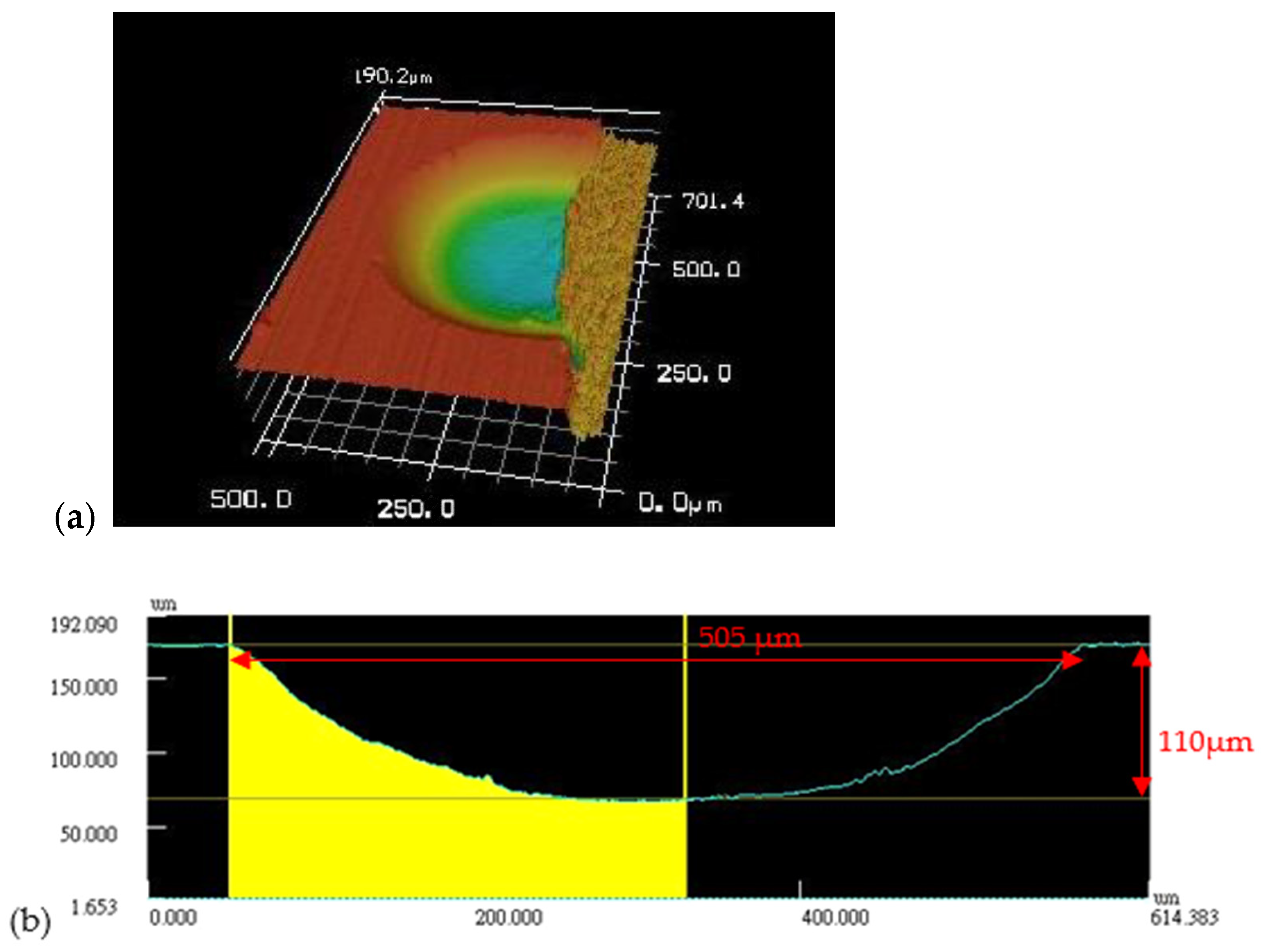
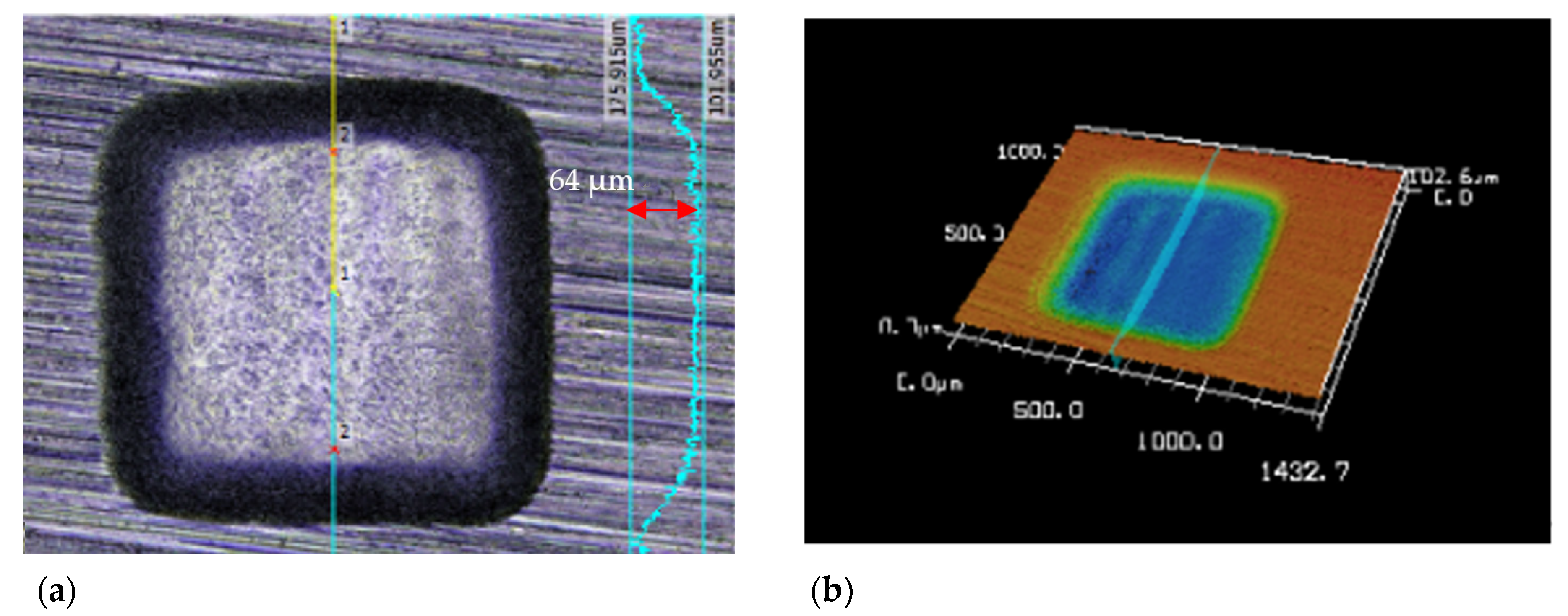
  • ECM milling with DI-water achieves a square insert of 0.6 × 0.6 mm2 at 64 μm depth with an integrated surface. A typical deep slot with 1.0 × 0.5 mm2 with a target depth of 100 μm is achieved with Ra 0.227 μm, although there is a depth expansion to 110 μm through 10 layers of milling. Two layers of the ECM milling can also achieve the S-shaped microchannels with 1.0 to 2.0 mm diameters.
Therefore, microsphere ECM drilling can be achieved with only one-step processing. A deeper ECM milling with several-layer operation reveals it is a convenient and cost-effective process on a single micro-EDM machine, achieving microcavity fabrication in micro mold applications.

Author Contributions

Conceptualization, A.W.-J.H.; Data curation, Z.-Y.H.; Formal analysis, A.W.-J.H.; Investigation, A.W.-J.H. and Z.-Y.H.; Methodology, A.W.-J.H. and Z.-Y.H.; Project administration, A.W.-J.H.; Resources, A.W.-J.H.; Validation, A.W.-J.H. and Z.-Y.H.; Visualization, Z.-Y.H.; Writing—original draft, review & editing, A.W.-J.H. and Z.-Y.H. All authors have read and agreed to the published version of the manuscript.

Funding

This research was partially funded by Grant No: MOST 107-2221-E-992-058-, from the Ministry of Science and Technology, Taiwan.

Institutional Review Board Statement

Not applicable.

Informed Consent Statement

Informed consent statement was obtained from all subjects involved in the study.

Data Availability Statement

The data and materials are available.

Acknowledgments

Many thanks to J.-C. Hung at NCU, Taiwan, and F.-C. Hsue at MIRDC for their advice.

Conflicts of Interest

The authors declare no conflict of interest.

References

  1. Minh, D.N.; Mustafizur, R.; Yoke, S.W. Transitions of micro-EDM/SEDCM/micro-ECM milling in low-resistivity deionized water. Int. J. Mach. Tools Manuf. 2013, 69, 48–56. [Google Scholar]
  2. Li, Y.; Zheng, Y.; Yang, G.; Peng, L. Localized electrochemical micro machining with gap control. Sens. Actuators A 2003, 108, 144–148. [Google Scholar]
  3. Se, H.; Choi, B.H.K.; Hong, S.S.; Do, S.C.; Chong, N.C. Analysis of the electrochemical behaviors of WC–Co alloy for micro ECM. J. Mater. Proc. Technol. 2012, 213, 621–630. [Google Scholar]
  4. Yan, B.H.; Chen, S.L. Characteristics of SKD11 by complex process of electrical discharge machining using liquid suspended with alumina powder. J. Jpn. Inst. Met. 1994, 58–59, 1067–1072. [Google Scholar] [CrossRef] [Green Version]
  5. Furutani, K.; Saneto, A.; Takezawa, H.; Mohri, N.; Miyake, H. Accretion of titanium carbide by electrical discharge machining with powder suspended in working fluid. Precis. Eng. J. Int. Soc. Prec. Eng. Nano Technol. 2001, 25, 138–144. [Google Scholar] [CrossRef]
  6. Chun-Chieh, H. The Al2O3 Particles Electrophoretic Deposition Is Used To Finish Edmed Surface. Master’s Thesis, Department of Mech. Eng. at National Central University, Taoyuan, Taiwan, 2004. [Google Scholar]
  7. Kumar, N.; Mandal, N.; Das, A.K. Micro-machining through electrochemical discharge processes: A review. Mater. Manuf. Proc. 2020, 35, 363–404. [Google Scholar] [CrossRef]
  8. Huaiqian, B.; Jiawen, X.; Ying, L. Aviation-oriented Micromachining Technology-Micro-ECM in Pure Water. Chin. J. Aeronaut. 2008, 21, 455–461. [Google Scholar] [CrossRef] [Green Version]
  9. Ivanov, A.; Leese, R.; Spieser, A. Micro-Electrochemical Machining. Micromanufacturing Engineering and Technology, 2nd ed.; William Andrew: Waltham, MA, USA, 2015; pp. 121–145. [Google Scholar]
  10. Kumar, K.; Saxena; Qiana, J.; Reynaerts, D. A review on process capabilities of electrochemical micromachining and its hybrid variants. Int. J. Mach. Tools Manuf. 2018, 127, 28–56. [Google Scholar]
  11. Yehia, H.M.; Hakim, M.; El-Assal, A. Effect of the Al2O3 powder addition on the metal removal rate and the surface roughness of the electrochemical grinding machining. Proc. Inst. Mech. Eng. Part B J. Eng. Manuf. 2020, 234, 1538–1548. [Google Scholar] [CrossRef]
  12. Wüthrich, R.; Hof, L.A.; Lal, A.; Fujisaki, K.; Bleuler, H.; Mandin, P.; Picard, G. Physical principles and miniaturization of spark assisted chemical engraving (SACE). J. Micromecha. Microeng. 2005, 15, S268–S275. [Google Scholar] [CrossRef]
  13. Sandip, S.; Bhattacharyya, B. Experimental investigation into micromilling of microgrooves on titanium by electrochemical micromachining. J. Manuf. Proc. 2017, 28, 286–294. [Google Scholar]
  14. Mullya, S.A.; Karthikeyan, G.; Ganachari, V.S. Electric discharge milling: A state-of-the-art review. J. Braz. Soc. Mech. Sci. Eng. 2021, 43, 424. [Google Scholar] [CrossRef]
  15. Nguyen, M.D.; Rahman, M.; Wong, Y.S. Simultaneous micro-EDM and micro-ECM in low-resistivity deionized water. Int. J. Mach. Tools Manuf. 2012, 54, 55–65. [Google Scholar] [CrossRef]
  16. Nguyen, M.D.; Rahman, M.; Wong, Y.S. Modeling of the radial gap formed by material dissolution in simultaneous micro-EDM and micro-ECM drilling using deionized water. Int. J. Mach. Tools Manuf. 2013, 95, 48–56. [Google Scholar] [CrossRef]
Figure 1. Redraw of a typical polarization curve [9]. The axis of ordinates is described in the logarithm of the current density (ASD) up to 1, and potential voltage is up to several volts for steel.
Processes 10 00152 g001
Figure 2. Three steps of microtool dressing: (1) roughing with 0.5 A to 400 µm, (2) finishing with 50 mA to 350 µm, and (3) finished spherical tooltip formation.
Processes 10 00152 g002
Figure 3. Tool design based on the distribution of electricity flux of the (a) cylinder tooltip and (b) spherical tooltip.
Processes 10 00152 g003
Figure 4. (a) Setup of the DI-water ECM tanks and hybrid abrasive ECM; (b) typical pulse waveform of the DC power supply. CH1: Voltage (V) × 1/150, CH2: Current (mA) × 1/180.
Processes 10 00152 g004
Figure 5. Preliminary tests of ECM work surface with spherical tooltip of (a) 150 µm, (b) 250 µm, (c) 350 µm, and (d) WEDG dressed profile of the spherical tooltip with a diameter of 350 µm.
Processes 10 00152 g005
Figure 6. Two types of micro mold cavity made by (a) ECM drilling and (b) micro ECM milling.
Processes 10 00152 g006
Figure 7. Effect of peak current on craters of the bottom surface with (a) 50 mA, (b) 100 mA, (c) 200 mA, and its effective circle (SEM 1000×). (d) The effective diameter of damaged crater circle vs. current.
Processes 10 00152 g007
Figure 8. ECM drilling performance of pulse on-time TON: (a) 0.1 ms, (b) 0.2 ms, (c) 0.4 ms.
Processes 10 00152 g008
Figure 9. ECM drilling with TON 0.2 ms ,   and   various   feed   rate   of   (a) 20 µm/min, (b) 30   μ m / min, (c) 40 μ m / min. (d) Machined depth vs. the feed rate conditions.
Processes 10 00152 g009
Figure 10. Cavity bottom profile results from (a) DI-water ECM, (b) hybrid ECM polishing with alumina abrasives.
Processes 10 00152 g010
Figure 11. Comparison of the surface with (a) DI-water ECM, (b) hybrid alumina abrasive ECM polishing (×2000). (c) Surface roughness of ECM polishing schemes vs. pulse on-time TON.
Processes 10 00152 g011
Figure 12. ECM slot milling with feed rate of (a) 10   μ m/min, (b) 30 μ m/min, (c) 60   μ m/min (d) OM picture of the slot with feed rate of (a).
Processes 10 00152 g012
Figure 13. Slot profile by ECM milling along the centerline at the bottom is conducted by a feed rate of (a) 30 µm/min, (b) 60 µm/min.
Processes 10 00152 g013
Figure 14. ECM milling of a deep slot in (a) 3D morphology and (b) profile of its cross-section over its width direction.
Processes 10 00152 g014
Figure 15. Comparison between (a) kerosene micro-EDM and (b) DI-water ECM with (c,d) microspherical tool of 0.35 mm diameter in one-step processing.
Processes 10 00152 g015
Figure 16. The morphology and profile of a square cavity were conducted by ECM milling. (a) The scanning line reveals the depth of cavity is 64 µm, (b) the 3D profile of the cavity.
Processes 10 00152 g016
Figure 17. (a) The morphology of the micro S-channel with 1.0 diameter, and (b,c) 3D profiles of the middle section of the S-channel with 2.0 mm diameter; the scanning line reveals z-coordination from 100.3 to 134.8 µm and the cross-section profile.
Processes 10 00152 g017
Table 1. Operational conditions of ECM with a tank retrofitted from the micro-EDM machine.
Feed Rate (µm/min)203040
Spindle Revolution (rpm)500
Target Depth (mm)0.02
C-CodeTON (ms)TOFF (ms)Current (mA)Voltage (V)
C10.10.85030
C20.20.85030
C30.40.85030
C50.30.810030
C70.20.820030
Table 2. Alumina particles concentration for abrasiveness.
Peak Current (mA)100
Rotation speed (rpm)500
Concentration (g/L)51525
Time (min)5710
Table 3. Operational conditions for DI-ECM and hybrid ECM with alumina powder.
ElectrolyteDI-WaterDI Water + Alumina
Peak current (mA)5050
TON On-time (ms)0.1, 0.2, 0.40.1, 0.2, 0.4
TOFF Off-time (ms)0.80.8
Gap voltage(V)3535
Spindle speed(rpm)500500
Tool polarity(-)(-)
Feed rate (µm/min)3030
Table 4. Operation conditions for slot milling with deionized water.
C-CodeC2
Rotation speed (rpm)500
Feed rate (μm/min)103060
Depth (mm/layer)0.01
Slot length (mm)0.5
CodeTON (m s )TOFF (m s )Current (mA)Voltage (V)
C2:0.20.85030
Table 5. Comparison of the ECM milling surface roughness Ra vs. peak current and Ra vs. feed rate.
Peak current (mA)50100200
Roughness Ra (μm)0.1880.2730.337
Feed rate (μm/min)103060
Roughness Ra (μm)0.1510.1320.210
Publisher’s Note: MDPI stays neutral with regard to jurisdictional claims in published maps and institutional affiliations.

