Article

Bottom-Up Synthesis of Mesoporous TiO2 Films for the Development of Optical Sensing Layers

by
David Ortiz de Zárate
*,
Sara Serna
,
Salvador Ponce-Alcántara
,
Miroslavna Kovylina
and
Jaime García-Rupérez
*
Nanophotonics Technology Center, Universitat Politècnica de València, Camí de Vera s/n, 46022 València, Spain
*
Authors to whom correspondence should be addressed.
Chemosensors 2021, 9(12), 329; https://doi.org/10.3390/chemosensors9120329
Submission received: 18 October 2021 / Revised: 17 November 2021 / Accepted: 20 November 2021 / Published: 25 November 2021
(This article belongs to the Special Issue Innovative Materials, Technologies, and Sensors)

Abstract

:
Many optical sensors exploit the interesting properties of porous materials, as they ensure a stronger interaction between the light and the analyte directly within the optical structure. Most porous optical sensors are mainly based on porous silicon and anodized aluminum oxide, showing high sensitivities. However, the top-down strategies usually employed to produce those materials might offer a limited control over the properties of the porous layer, which could affect the homogeneity, reducing the sensor reproducibility. In this work, we present the bottom-up synthesis of mesoporous TiO2 Fabry-Pérot optical sensors displaying high sensitivity, high homogeneity, and low production cost, making this platform a very promising candidate for the development of high-performance optical sensors.

1. Introduction

Sensors boost the human ability to interact with the environment, in order to conceive new devices making our lives better, easier, and safer. They are mainly designed to exploit mechanical, physical, chemical, optical, or electromagnetic transduction mechanisms in order to identify and quantify specific analytes such as proteins, antibodies, DNA/RNA, pathogens, or contaminants with interest in a wide range of fields like healthcare [1,2], environmental monitoring [3,4], food control [5,6], drug development [7,8], or defense [9,10], among many others.
Among the different transduction methods that can be found for the development of sensing devices, those based on optical technology exhibit a high potential because of their high sensitivity, high degree of miniaturization, short time to result, label-free detection, requirement of very low volumes of sample and reagents, resistance to hazardous and harsh environments, and immunity to electromagnetic interferences [11]. Many of these optical sensors are based on the measurement of the refractive index changes that are produced when the analyte is placed in the vicinities of the sensing structure. Typically, the evanescent field of a guided mode propagated within the optical structure is used to interact with the surroundings, being able to detect the variations in the mode effective index produced by the presence of the analyte [12,13]. However, that evanescent field only represents a small portion of the field being propagated through the optical structure, thus significantly limiting the light-analyte interaction and thus the sensibility.
Therefore, there is a growing interest in the development of new configurations of optical sensors where the interaction of the light with the analyte is maximized. To this aim, nanostructured materials arise as a remarkable solution because of their unique physicochemical features in comparison with their bulk counterparts: high surface-to-volume ratio, small size, or tunable refractive index, among many others [14]. Thus, nanostructure-based sensors show an enhanced performance (i.e., fast response time, higher sensitivity, lower limit of detection, etc.) [15]. As a particular case of these nanostructured materials, the use of porous materials to create new optical structures maximizes the interactions taking place at the nanoscale between the light, the sensor, and the analyte. When using porous materials, the analytes can go inside the optical structure through the pore network, making all the optical field within the whole sensing structure capable to interact with them, both on the surface and within the pores. As a result, porous optical sensors display higher efficiency and sensitivity. Additionally, that porous nature also provides a significant increase of the available surface for the immobilization of bioreceptors for the specific detection of the analytes in comparison to the case when only the external surface is used to this aim, thus leading to a further increase of the efficiency and the sensitivity.
Most porous optical sensors are based on porous silicon (PSi) and on anodic aluminum oxide (AAO) layers, showing sensitivities even above 1000 nm/RIU (Refractive Index Unit) in the near infrared (NIR) range of the spectrum for PSi [16] and of 441 nm/RIU in the visible (VIS) range for AAO [17]. However, these structures are typically fabricated using top-down strategies, where the bulk material is anodized to create the porous structure by applying an electric current in an acid solution [18,19]. This fabrication process can lead to a limited control over the properties of the porous layer both in depth and along its surface [20]. On one hand, as the new pores are created through the previously fabricated porous layer, the etching conditions will change, thus making the pores properties change when going deeper into the layer. On the other hand, the cathodes typically used for the anodization of these porous substrates do not provide an etching current that is perfectly homogeneous all over the surface, thus making the fabricated layers might count on quite different properties depending on the location. Therefore, the large-scale production of optical sensors based on these nanostructured materials is seriously hampered by the limitations of these top-down strategies.
Alternatives for the bottom-up fabrication of porous layers, where they are grown over a substrate instead of etching a bulk material, have been also proposed. This is the case, for example, of polymeric nanofibers (NFs) layers, which consist of a mesh of these NFs that can be simply, quickly, and inexpensively fabricated by electrospinning techniques. By properly adjusting the electrospinning process parameters, it is possible to obtain NFs with diameters of only few tens of nanometers, which allow porous layers with an optical response. These NFs-based optical sensors have also shown significantly high sensitivities even above 1000 nm/RIU in the NIR range [21]. However, despite these high sensitivity values, their sensing performance is limited by the broad width of the spectral features to be tracked to perform the sensing, which increases the measured noise and reduces the achievable limit of detection. This limitation is determined by the reduction of the specular reflection when the thickness of the layer is increased and by the low index of the constitutive polymeric materials.
In this work, we propose the bottom-up synthesis of mesoporous films for the fabrication of optical sensors based on Fabry-Pérot interferometry (or thin film interferometry). TiO2 has been selected as constitutive material of the films because its high refractive index (~2.56) will allow the effective index of the porous layers to be high enough to provide an adequate optical response in an aqueous environment, circumventing the limitation previously commented for the polymeric NFs. Additionally, TiO2 also offers other potential advantages for the development of biosensors such as high chemical and mechanical stability, non-toxicity, or self-cleaning properties by means of UV-light exposure for certain applications, among others [22,23].
Several methods have been proposed for the synthesis of TiO2 porous layers (e.g., sol-gel, hydrothermal, solvothermal, template-based, etc.) [22], which have been typically used to increase the sensitivity of electrochemical [24,25], plasmonic [26,27], or fiber-based [28] sensors due to the higher surface-to-volume ratio that they provide. Other works have reported the creation of porous optical sensing layers using more complex fabrication techniques such as physical vapor deposition in glancing angle configuration (GLAD-PVD) [29,30,31] or also by anodization [23,32,33], with the limitations previously indicated for PSi and AAO substrates. TiO2 porous layers have also been used for the creation of Fabry-Pérot interferometers directly on the tip of an optical fiber using techniques such as e-beam evaporation [34,35] or liquid phase deposition (LPD) [36].
In our case, we have followed the sol-gel route [37,38] and the evaporation induced self-assembly (EISA) methods [39] for the synthesis of mesoporous TiO2 layers. These two methods provide a better control of the size and the arrangement of the mesopores, improving homogeneity, and providing large surface area, low production cost and manufacturability over large areas. All those advantages are then exploited to fabricate Fabry-Pérot optical structures, which are presented as excellent candidates for the development of low-cost and high-performance porous optical sensors.

2. Materials and Methods

All the chemical reagents used in this work for the synthesis and deposition of mesoporous TiO2 films were supplied by Scharlab (Barcelona, Spain) (Acetone, Ethanol, and Isopropanol), TCI (Tokyo, Japan) (Titanium Tetraisopropoxide, TTIP) and Sigma-Aldrich (Burlington, VT, USA) (Pluronic F127 and P123 block copolymers, Hydrochloric acid, and 1-Butanol).
The silicon substrates were supplied by Siegert Wafer (Aachen, Germany) and sliced into smaller pieces of 15 × 15 mm2 and 30 × 30 mm2 by means of an automatic dicing saw Disco DAD3350 (Disco Co., Tokyo, Japan). Previously to any deposition, the substrates were thoroughly cleaned by consecutive rinsing with acetone, isopropanol, and deionized water, followed by a drying step with a mild flow of nitrogen gas.

2.1. Preparation of TiO2 Sol

2.1.1. F127-Templated TiO2 Sol

A stable homogeneous sol was obtained by adapting the EISA method previously reported for pure [40] and multi-nanocrystalline transition metal oxide (TiO2–NiTiO3) mesoporous thin films [41]. The sol was prepared by hydrolyzing TTIP in an acidic mixture of ethanol and water in the presence of F127 (EO70PO106EO70) block copolymer. The final molar ratio was Ti:40 EtOH:10 H2O:0.004 F127:H2SO4. Typically, 0.067 g of F127 was gently dissolved in 2.3 mL of ethanol, and then 50 µL of H2SO4 was added to the solution in order to promote an acidic medium preventing the TiO2 precipitation. 297 µL of TTIP was carefully added to the solution. Finally, 180 µL of deionized water was carefully added to the final solution to promote the condensation of TiO2. Then, the chemical reagents were mixed for 10 min at room temperature under magnetic stirring in a fume hood, and a stable, colourless, and transparent solution (the sol) was finally obtained.

2.1.2. P123-Templated TiO2 Sol

A stable homogeneous sol was obtained by adapting the method previously reported for the synthesis of 3D hexagonal mesostructured TiO2 [42], modifying the reagents (i.e., titanium source) and the experimental conditions (i.e., sol aging time and film aging conditions). In this case, the sol was prepared by hydrolyzing TTIP in an acidic mixture of 1-butanol and water in the presence of P123 (EO20PO70EO20) block copolymer. The final molar ratio was Ti:2 HCl:0.013 P123:9 1-Butanol. Typically, 1.34 mL of concentrated hydrochloric acid was carefully added to 2.56 mL of TTIP at room temperature under stirring, in order to provide an acidic environment preventing the precipitation of TiO2. At the same time, a second solution was prepared at room temperature under vigorous stirring by mixing 0.65 g of the surfactant P123 and 6 g of 1-Butanol, acting as enhancer of the phase separation between the template and the inorganic framework, and as swelling agent, boosting the expansion of pores. Once the surfactant was completely dissolved, this solution was added to the acidic TTIP solution and stirred for 30 min, enabling the sol aging.

2.2. Preparation of Mesoporous TiO2 Films

2.2.1. F127-Templated Mesoporous TiO2 Films

Films were obtained by spin-coating the aged sol on pre-cleaned Si substrates under controlled conditions (21 °C and relative humidity (RH) of 42%) by means of an EVG101 spin-coater (EV Group, Sankt Florian am Inn, Schärding, Austria) placed in a class 100 cleanroom. Films thus prepared were aged overnight under different conditions (RH of 45% and 60%), enabling highly uniform mesostructured TiO2 films with an optical Fabry-Pérot response. Those films were subsequently thermally treated to remove the organic surfactant and to enhance their mechanical and thermal resistance, providing highly uniform mesoporous films with an optical Fabry-Pérot response. The thermal treatment consisted in a calcination under air atmosphere, by heating at a rate of 5 °C/min to 60 °C, 100 °C, and 130 °C, and then holding 24 h at each temperature to promote a higher crosslinking of titania. Then the template removal was performed by thermal degradation, heating at a rate of 5 °C/min to the desired temperature (300–450 °C).

2.2.2. P123-Templated Mesoporous TiO2 Films

Films were obtained by spin-coating the aged sol on pre-cleaned Si substrates under controlled conditions (21 °C and RH of 42%) by means of an EVG101 spin-coater placed in a class 100 cleanroom. Films thus prepared were aged overnight under different conditions (RH of 60% and 95%), enabling highly uniform mesostructured TiO2 films with an optical Fabry-Pérot response. Those films were subsequently thermally treated to remove the organic surfactant and to enhance their mechanical and thermal resistance, providing highly uniform mesoporous films with optical Fabry-Pérot response. The thermal treatment was again a calcination under air atmosphere, by heating at a rate of 1 °C/min to 300 °C to promote a higher crosslinking of titania, then holding for 1h to complete the template removal by thermal degradation, and then heating at a rate of 10 °C/min to the desired temperature (300–400 °C), to enable the nucleation and growth of TiO2 nanocrystallites within the framework.

2.3. Characterization of TiO2 Films

Transmission Electron Microscopy (TEM) images of the porous films were acquired with a JEOL JEM 1400 microscope (JEOL Ltd., Akishima, Tokyo, Japan) operated at 120 kV, while High Resolution Field Emission Scanning Electron Microscopy (HRFESEM) images were obtained with a Zeiss GeminiSEM 500 equipment (Zeiss, Oberkochen, Germany), operated at low voltage (0.02–2 kV). The thickness of the porous films was experimentally determined by means of a Veeco Dektak150 profilometer (Veeco, Plainview, NY, USA). Finally, the optical response of the porous films was assessed by measuring the film reflectivity in the UV-Vis-NIR range using a homemade measurement platform where light from a halogen lamp was used to illuminate the sample and an Ocean Optics spectrometer model Flame T (Ocean Optics, Orlando, FL, USA), operated with the Ocean View software, was used to obtain the reflection spectrum. The refractive index of porous films was estimated by the Transfer Matrix Method [43], and the Bruggeman effective medium theory was employed to estimate the porosity [44]. Assuming that the pores are exclusively filled with air, the film porosity can be calculated on the basis of the simplified Bruggeman effective medium approximation (BEMA) [45], by means of the following equation:
n 2 1 n 2 + 2   =   1 P n d 2 1 n d 2 + 2

3. Results and Discussion

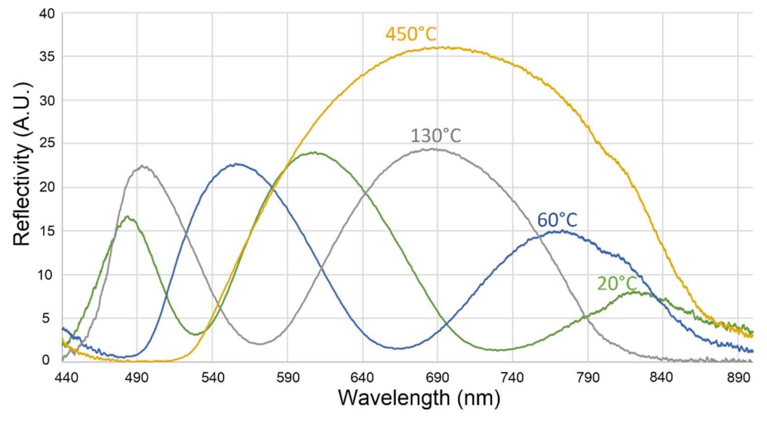
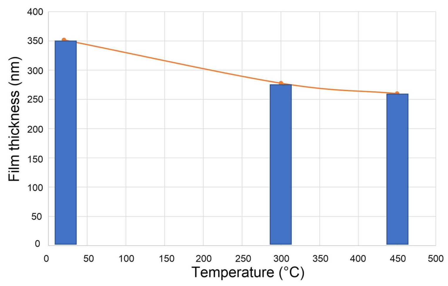
3.1. F127-Templated Mesoporous TiO2 Films

The mesostructured TiO2 films were obtained by spin-coating the aged sol using different conditions. After several iterations, the employment of 3000 rpm and 15 s provided homogeneous and stable films. As in any EISA strategy [39], the conditions of film aging (especially the relative humidity), might influence the arrangement of mesopores, because of the important role of water in this re-organization during the evaporative phase and also the aging process [46]. Thus, aging the films at RH of 45% and 60% enabled highly uniform TiO2 films with a different Fabry-Pérot optical response (see Figure 1). All the films displayed an optical response counting on three lobes on the measured reflectance spectrum. These lobes are produced by the constructive-destructive interferences produced in the TiO2 film due to the reflections occurring at its interfaces with the lower silicon substrate and the upper air medium. Those lobes for the films obtained with RH of 60% counted on a higher maximum-to-minimum amplitude and were shifted to lower wavelengths, probably because the higher water content at 60% RH enabled a deeper reorganization of the mesostructure, thus promoting a better arrangement of the mesopores and therefore a lower effective thickness of the film.
TiO2 mesostructured films were subsequently thermally treated to remove the organic surfactant and to enhance their mechanical and thermal resistance, providing highly uniform mesoporous films with optical response (see Figure 2). At room temperature (20 °C), the optical reflectance spectrum displayed three lobes between 450 and 850 nm, which were shifted towards lower wavelengths and widened when the temperature was risen. Thus, only two lobes were observed after thermal treatment at 60 and 130 °C, and only one lobe was registered in the optical spectrum after calcination at 450 °C. This blue-shift effect is explained by the higher film contraction that is produced during the thermal treatment process with increasing temperatures, which produces a modification of the effective thickness of the film.
The film thickness contraction with the increase of temperature during the calcination process is experimentally verified by profilometry measurements after each thermal treatment (see Figure 3). Initially, the film aged at room temperature (20 °C) and RH of 60% counts on a thickness of 350 ± 5 nm. That thickness of the film is reduced to 280 ± 5 nm when the calcination is performed at 300 °C, and to 258 ± 5 nm when it is performed at 450 °C, thus showing a stabilization of the thickness reduction for this temperature range. This is in agreement with the experimental results previously observed for the optical reflectance spectra of the films, where a shift towards lower wavelengths was observed.
The careful thermal treatment enhanced condensation reactions leading to a higher crosslinking of the inorganic network, stabilizing the mesostructure and promoting a higher mechanical and chemical resistance, and enabled the template removal by thermal degradation. After that process, the mesoporous TiO2 film was finally obtained. The fabricated samples were inspected by TEM microscopy in order to verify the porous nature of the films (see Figure 4), as well as the pore sizes and their pore arrangement. A mesoporous material could be appreciated, with ordered mesopores of 3–4 nm (in agreement with the sizes of F-127 surfactant micelles) following a uniform distribution. This pore arrangement might be 3D hexagonal or cubic, both of them interesting for sensing purposes because they provide an interconnected network of pores that enables an adequate infiltration of the substances to be analyzed.
Finally, the possibility of creating multilayer mesoporous films in order to increase the thickness was assessed by repeating the synthesis process several times over the same substrate. This will theoretically allow the obtainment of a higher number of lobes in the spectrum, so that they will be narrower and thus easier to track when performing the sensing experiments. Figure 5 demonstrates this effect was obtained for two and three consecutive layers of mesoporous TiO2. Regarding the reflectivity of the film, it slightly decreases as the number of deposited layers is increased, although the lobes are still being clearly defined. Regarding film uniformity, it is degraded when the third porous layer is deposited, but not for the second. This indicated that further attention might be required to study the adhesion between them.

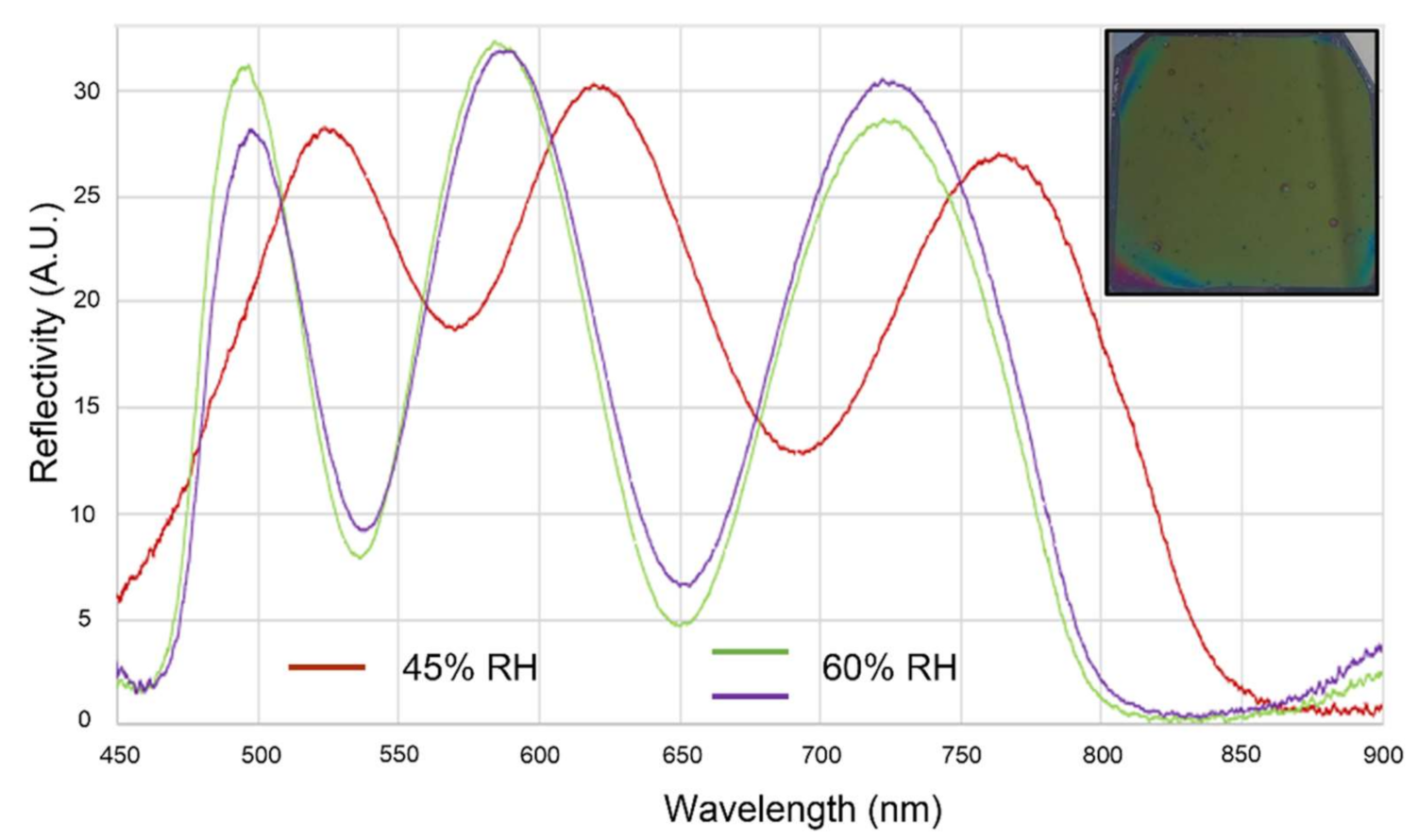
3.2. Sensing Experiments with F127-Templated Mesoporous TiO2 Films

Once the fabrication process for the creation of the F127-templated mesoporous TiO2 films was optimized, their sensing performance as Fabry-Pérot interferometers was assessed by measuring the spectral shift that was produced in the fringes pattern when flowing solutions of different refractive indices over the porous samples. A film consisting of a single layer of F127-templated mesoporous TiO2 was used in the experiments, as it exhibited a higher surface uniformity and a higher reflectivity, as previously depicted (further optimization is required for the multilayer films). A home-made microfluidic cell was placed on top of the mesoporous TiO2 samples in order to deliver the target substance, which will fill the pores of the film and replace the air previously contained on them, thus disturbing the effective refractive index in a quantitative manner. Water was chosen to perform the sensing experiments as it is non-toxic, non-destructive, and the main solvent used in most analyses. Optical reflectance spectra were continuously acquired in the VIS-NIR range (450–900 nm) with the aim of determining the position of the interferometric lobes and track their shift when the refractive index is changed.
Figure 6a shows the spectral shift measured during the infiltration of water in a F127-templated mesoporous TiO2 film. The spectral shift is determined from the change in the position of the maximum, initially located around 615 nm. After the entry of water in the porous layer, a shift towards longer wavelengths of 43 nm is registered during the following 18 h (with automatic measurements programmed with the Ocean View software), meaning an experimental sensitivity around 129 nm/RIU. However, it can be observed in Figure 6b that the response of the sensing layer is extremely slow: it takes around 3 h for the sensing film to show a shift of ~33 nm and continuous slow shifting during the following 15 h of the experiment. Considering this slow response, we left the sensing film under the water environment for the following 17 days and obtained an additional shift of 110 nm (only one measurement was performed at the end of that time period). Taking the whole spectral shift into account, an experimental sensitivity of 458 nm/RIU is determined, estimating a porosity of 75% and an effective index of the TiO2 layer of 1.308.
Therefore, despite the remarkable final sensitivity measured for the fabricated F127-templated mesoporous TiO2 Fabry-Pérot optical sensor, its response was extremely slow (hours or even days are required for the shift to take place), making it unpractical for real sensing purposes, where typically response is expected to be obtained within few minutes. This slow response is due to the reduced size of the pores obtained using this synthesis route (3–4 nm), which makes it difficult for the liquids to infiltrate into the porous structure.

3.3. P123-Templated Mesoporous TiO2 Films

As the micelles of P123 surfactant are bigger than those of F127, bigger pores suitable for liquid sensing purposes were expected following this route, thus potentially solving the limitations observed in the previous experiments. Again, the mesoporous TiO2 films were obtained by spin-coating the aged sol using different conditions, determining that the employment of 3000 rpm and 15 s provided homogeneous and stable films. According to bibliography, the film aging process should be conducted at RH of 95% for 24 h in order to achieve a cubic arrangement of the mesostructure. However, the uniform TiO2 films obtained after the spin-coating step through this modified procedure almost dissolved in water after 24 h at high RH. As a consequence, different RHs were tested in order to find the optimal conditions to reach a 3D hexagonal or cubic arrangement of the mesopores when using this procedure. A RH of 60–70% was found to be optimal to obtain an arrangement of pores with a diameter of 15–20 nm, exhibiting order at short distances, as was verified by HRFESEM inspection of the P123-templated mesoporous TiO2 films (see Figure 7). Then, the samples were thermally treated with the aim of obtaining P123-templated mesoporous TiO2 films.
The optical Fabry-Pérot response of the fabricated TiO2 films was also assessed (see Figure 8). As was previously observed for the F127-templated mesoporous films, a shift of the spectral response towards shorter wavelengths and a widening of the spectral lobes was again observed when the film was thermally treated, due to the thermal contraction promoting a lower film thickness. Additionally, following our previous experience with the F127-templated films, multilayer P123-templated mesoporous TiO2 films were also prepared by subsequent processes of deposition and aging in order to increase the layer thickness. These multilayer films kept displaying a high reflectivity up to three layers, increasing the number of lobes and reducing their width, thus improving the sensing capabilities of the film. Additionally, we can observe that now a very good surface homogeneity is maintained after the deposition of the three layers.

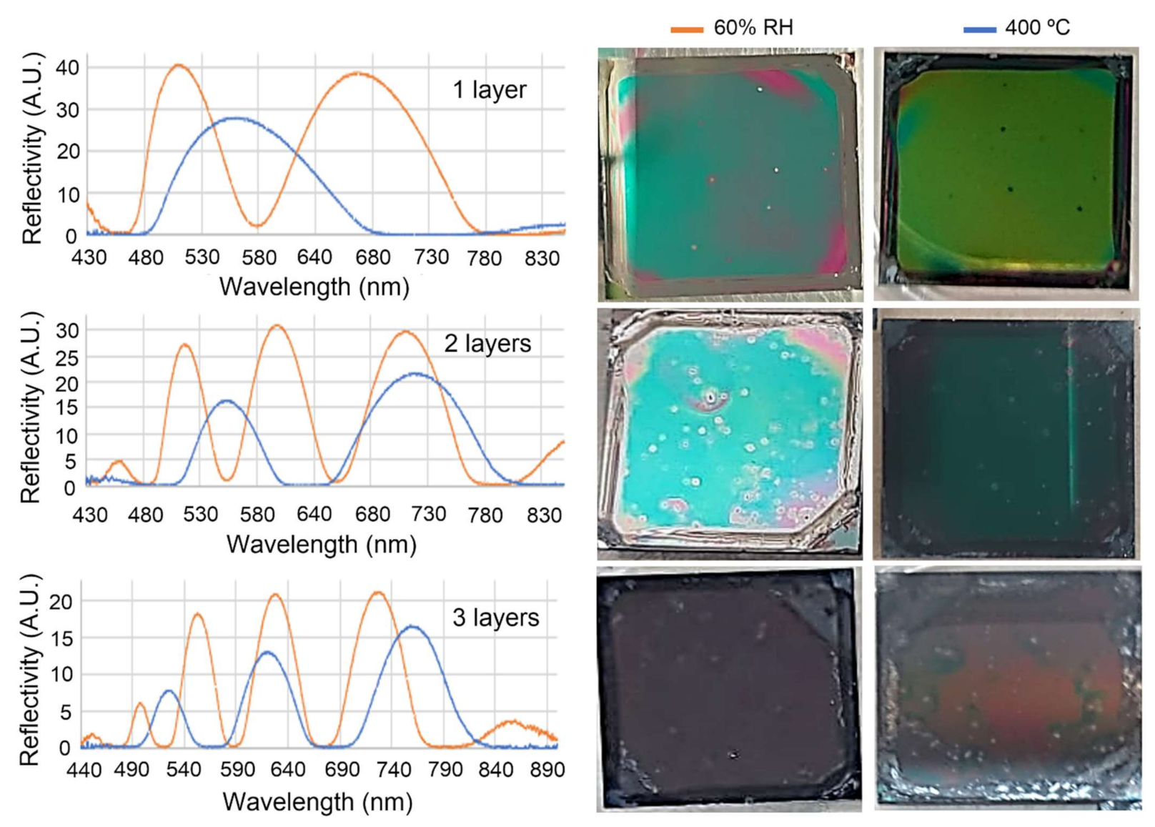
3.4. Sensing Experiments with P123-Templated Mesoporous TiO2 Films

The sensing performance of P123-templated mesoporous TiO2 films acting as Fabry-Pérot interferometers was also assessed by filling the pores of the structure with water (by using the microfluidic cell previously indicated) in order to change its effective refractive index and registering the spectral shift in the VIS-NIR range. For a more direct comparison with the experiments carried out with the F127-templated mesoporous TiO2 film, a single layer film was used in the current experiments. Figure 9a shows the change in the optical reflectance spectrum measured during the infiltration of water in the mesoporous TiO2 layer. As can be observed, the minimum of the lobe located within the measurement range (initially at 625 nm) experienced a shift of 95 nm when the water was flowed over the porous sensor. According to the measured spectral shift, an experimental sensitivity of 288 nm/RIU is determined, estimating a porosity of 55% and an effective index of the TiO2 layer of 1.636. Regarding the temporal behavior of the porous film, Figure 9b shows that its sensing response is instantaneous once the liquid reaches it. Additionally, the measured shift remains constant after that moment, indicating that the pores of the film have been properly filled and that the sensor has reached a stable response. Therefore, the bigger size of the pores using the P123-based synthesis route allows the overcoming of the limitations previously observed during the sensing experiments for the F127-based films.
The lower sensitivity obtained for the P123-templated mesoporous TiO2 films in comparison with that of F127-templated mesoporous TiO2 films is explained by the different porosity estimated for each case. Despite the bigger pores obtained for the P123-based films, the porosity is smaller than that obtained for the F127-based films (~55% vs. ~75%), thus leading to a lower volume inside the porous structure where the sensing is carried out (i.e., where the medium is changed from air to water, for the case of our experiments). On the other hand, the lower porosity with bigger pores of the P123-based films also suggests a bigger thickness of the pore walls, which provides the sensing layer with good mechanical stability, which is also relevant for the practical development of sensing devices.

4. Conclusions

F127- and P123-templated mesoporous TiO2 films have been synthesized using a low-cost and easy to implement sol-gel route that allows a bottom-up fabrication of porous optical sensing layers, as opposed to more typical top-down fabrication approaches based on anodization of a bulk material. By properly adjusting the process parameters (e.g., molar relations within the sol, sol aging time, spin-coating speed and time, film aging RH and time, calcination temperature), it is possible to obtain mesoporous TiO2 layers with thicknesses in the range of few hundreds of nanometers, controlled pore size and pore arrangement, and good surface homogeneity, thus overcoming the typical limitations of top-down fabrication strategies and enabling a low-cost and large-scale bottom-up production process.
The fabricated mesoporous TiO2 films exhibit a Fabry-Pérot optical response in the VIS-NIR range, which allows them to perform sensing experiments by tracking the position of the interference fringes when changes in the refractive index of the environment are produced. Both types of films (F127- and P123-based) have demonstrated their sensing capability, showing sensitivities of ~458 nm/RIU and ~288 nm/RIU, respectively. Despite their higher sensitivity, the practical utility of the F127-templated mesoporous TiO2 films is limited by the extremely long times required for the liquids to go inside the pores, mainly due to their size (3–4 nm). This limitation is overcome by using the P123-templated mesoporous TiO2 films, where the bigger pore size (15–20 nm) and their high degree of interconnection allow an instantaneous sensing response.
Additionally, note that the proposed synthesis route enables the subsequent deposition of new porous layers over the previous ones, which increases the total thickness of the film in order to have narrower interference fringes that can be more accurately tracked. This capability is also very relevant for the alternate deposition of layers with different properties (e.g., pore size, porosity) with the aim of creating structures as Bragg reflectors or microcavities, which might allow a further improvement of the sensing performance.
Therefore, the synthesis of porous films using sol-gel routes appears as a very interesting alternative to typical etching-based approaches used for the fabrication of porous optical sensing layers. Additional work will be performed to demonstrate the utility of these mesoporous TiO2 layers in biosensing applications by biofunctionalizing the inner surface of the pores with specific bioreceptors, which will also allow us to demonstrate the potential reusability of the biosensors by exploiting the self-cleaning properties of TiO2.

Author Contributions

Conceptualization, D.O.d.Z. and J.G.-R.; methodology, D.O.d.Z. and J.G.-R.; validation, S.S., D.O.d.Z., M.K. and S.P.-A.; investigation, S.S., D.O.d.Z., M.K. and S.P.-A.; resources, J.G.-R.; writing—original draft preparation, D.O.d.Z.; writing—review and editing, J.G.-R., D.O.d.Z. and S.P.-A.; supervision, D.O.d.Z. and J.G.-R.; funding acquisition, J.G.-R. All authors have read and agreed to the published version of the manuscript.

Funding

This work was supported by the Spanish Ministerio de Ciencia e Innovación (MCIN/AEI/10.13039/501100011033) through the PID2019-106965RB-C21 project, by the Generalitat Valenciana through grant PPC/2021/036, and by the European Union through the operational program of the European Regional Development Fund (FEDER) of the Valencia Regional Government 2014-2020 and of the Ministerio de Ciencia e Innovación—Agencia Estatal de Investigación (Ref.ICTS-2017-28-UPV-9).

Institutional Review Board Statement

Not applicable.

Informed Consent Statement

Not applicable.

Acknowledgments

D. Ortiz de Zárate gratefully acknowledges the Electron Microscopy Service of the UPV.

Conflicts of Interest

The authors declare no conflict of interest. The funders had no role in the design of the study; in the collection, analyses, or interpretation of data; in the writing of the manuscript, or in the decision to publish the results.

References

  1. Murillo, A.M.M.; Tomé-Amat, J.; Ramírez, Y.; Garrido-Arandia, M.; Valle, L.G.; Hernández-Ramírez, G.; Tramarin, L.; Herreros, P.; Santamaría, B.; Díaz-Perales, A.; et al. Developing an Optical Interferometric Detection Method based biosensor for detecting specific SARS-CoV-2 immunoglobulins in Serum and Saliva, and their corresponding ELISA correlation. Sens. Actuators B Chem. 2021, 345, 130394. [Google Scholar] [CrossRef]
  2. Mohankumar, P.; Ajayan, J.; Mohanraj, T.; Yasodharan, R. Recent developments in biosensors for healthcare and biomedical applications: A review. Measurement 2021, 167, 108293. [Google Scholar] [CrossRef]
  3. Al Mamun, M.A.; Yuce, M.R. Recent Progress in Nanomaterial Enabled Chemical Sensors for Wearable Environmental Monitoring Applications. Adv. Funct. Mater. 2020, 30, 2005703. [Google Scholar] [CrossRef]
  4. Gonzalez, L.F.; Montes, G.A.; Puig, E.; Johnson, S.; Mengersen, K.; Gaston, K.J. Unmanned Aerial Vehicles (UAVs) and Artificial Intelligence Revolutionizing Wildlife Monitoring and Conservation. Sensors 2016, 16, 97. [Google Scholar] [CrossRef] [PubMed] [Green Version]
  5. Basnet, B.; Bang, J. The State-of-the-Art of Knowledge-Intensive Agriculture: A Review on Applied Sensing Systems and Data Analytics. J. Sens. 2018, 2018, 3528296. [Google Scholar]
  6. Mehrotra, P. Biosensors and their applications—A review. J. Oral. Biol. Craniofac. Res. 2016, 6, 153–159. [Google Scholar] [CrossRef] [Green Version]
  7. Unger, E.K.; Keller, J.P.; Altermatt, M.; Liang, R.; Matsui, A.; Dong, C.; Hon, O.J.; Yao, Z.; Sun, J.; Banala, S.; et al. Directed Evolution of a Selective and Sensitive Serotonin Sensor via Machine Learning. Cell 2020, 183, 1986–2002. [Google Scholar] [CrossRef] [PubMed]
  8. Namkung, Y.; LeGouill, C.; Kumar, S.; Cao, Y.; Teixeira, L.B.; Lukasheva, V.; Giubilaro, J.; Simões, S.C.; Longpré, J.M.; Devost, D.; et al. Functional selectivity profiling of the angiotensin II type 1 receptor using pathway-wide BRET signaling sensors. Sci. Signal. 2018, 11, eaat1631. [Google Scholar] [CrossRef] [PubMed] [Green Version]
  9. Fraga-Lamas, P.; Fernández-Caramés, T.M.; Suárez-Albela, M.; Castedo, L.; González-López, M. A Review on Internet of Things for Defense and Public Safety. Sensors 2016, 16, 1644. [Google Scholar] [CrossRef] [PubMed] [Green Version]
  10. Gupta, A.; Mishra, R.G. Implementation of Wireless Sensor Networks in the Field of Military and Defense: A Review. Viewpoint 2015, 6, 23–28. [Google Scholar]
  11. Osada, Y.; De Rossi, D.E. “Optical sensors”. In Polymer Sensors and Actuators; Springer: Berlin/Heidelberg, Germany; GmbH & Co. KG: Berlin, Germany, 2000; pp. 139–224. [Google Scholar]
  12. Luan, E.; Shoman, H.; Ratner, D.M.; Cheung, K.C.; Chrostowski, L. Silicon Photonic Biosensors Using Label-Free Detection. Sensors 2018, 18, 3519. [Google Scholar] [CrossRef] [Green Version]
  13. Ma, Y.; Dong, B.; Lee, C. Progress of infrared guided-wave nanophotonic sensors and devices. Nano Converg. 2020, 7, 12. [Google Scholar] [CrossRef] [PubMed] [Green Version]
  14. Moretta, R.; De Stefano, L.; Terracciano, M.; Rea, I. Porous Silicon Optical Devices: Recent Advances in Biosensing Applications. Sensors 2021, 21, 1336. [Google Scholar] [CrossRef]
  15. Pirzada, M.; Altintas, Z. Nanomaterials for Healthcare Biosensing Applications. Sensors 2019, 19, 5311. [Google Scholar] [CrossRef] [PubMed] [Green Version]
  16. Caroselli, R.; Martín Sánchez, D.; Ponce Alcántara, S.; Prats Quilez, F.; Torrijos Morán, L.; García-Rupérez, J. Real-Time and In-Flow Sensing Using a High Sensitivity Porous Silicon Microcavity-Based Sensor. Sensors 2017, 17, 2813. [Google Scholar] [CrossRef] [PubMed] [Green Version]
  17. Lee, J.; Bae, K.; Kang, G.; Choi, M.; Baek, S.; Yoo, D.; Lee, C.; Kim, K. Graded-lattice AAO photonic crystal heterostructure for high Q refractive index sensing. RSC Adv. 2015, 5, 71770–71777. [Google Scholar] [CrossRef]
  18. Bisi, O.; Ossicini, S.; Pavesi, L. Porous silicon: A quantum sponge structure for silicon based Optoelectronics. Surf. Sci. Rep. 2000, 38, 6–21. [Google Scholar] [CrossRef]
  19. Balde, M.; Vena, A.; Sorli, B. Fabrication of porous anodic aluminium oxide layers on paper for humidity sensors. Sensor Actuat. Biol. Chem. 2015, 220, 829–839. [Google Scholar] [CrossRef]
  20. De Stefano, L. Porous Silicon Optical Biosensors: Still a Promise or a Failure? Sensors 2019, 19, 4776. [Google Scholar] [CrossRef] [PubMed] [Green Version]
  21. Ponce-Alcántara, S.; Martín-Sánchez, D.; Pérez-Márquez, A.; Maudes, J.; Murillo, N.; García-Rupérez, J. Optical sensors based on polymeric nanofibers layers created by electrospinning. Opt. Mater. Express 2018, 8, 3163–3175. [Google Scholar] [CrossRef]
  22. Niu, B.; Wang, X.; Wu, K.; He, X.; Zhang, R. Mesoporous Titanium Dioxide: Synthesis and Applications in Photocatalysis, Energy and Biology. Materials 2018, 11, 1910. [Google Scholar] [CrossRef] [PubMed] [Green Version]
  23. Liang, F.; Kelly, T.L.; Luo, L.B.; Li, H.; Sailor, M.J.; Li, Y.Y. Self-cleaning organic vapor sensor based on a nanoporous TiO2 interferometer. ACS Appl. Mater. Interfaces 2012, 4, 4177–4183. [Google Scholar] [CrossRef] [PubMed]
  24. Benkstein, K.D.; Semancik, S. Mesoporous nanoparticle TiO2 thin films for conductometric gas sensing on microhotplate platforms. Sens. Actuators B Chem. 2006, 113, 445–453. [Google Scholar] [CrossRef]
  25. Amri, F.; Septiani, N.L.W.; Rezki, M.; Iqbal, M.; Yamauchi, Y.; Golberg, D.; Kaneti, Y.V.; Yuliarto, B. Mesoporous TiO2-based architectures as promising sensing materials towards next-generation biosensing applications. J. Mater. Chem. B 2021, 9, 1189–1207. [Google Scholar] [CrossRef] [PubMed]
  26. Zhang, Z.; Lu, D.-F.; Qi, Z.-M. Application of Porous TiO2 Thin Films as Wavelength-Interrogated Waveguide Resonance Sensors for Bio/Chemical Detection. J. Phys. Chem. C 2012, 116, 3342–3348. [Google Scholar] [CrossRef]
  27. Wan, X.; Lu, D.-F.; Gao, R.; Cheng, J.; Qi, Z.-M. Metal-Clad Waveguide Resonance Sensor Using a Mesoporous TiO2 Thin Film as the Chemical Sensitive Core Layer. J. Phys. Chem. C 2017, 121, 19173–19181. [Google Scholar] [CrossRef]
  28. Davies, E.; Viitala, R.; Salomäki, M.; Areva, S.; Zhang, L.; Bennion, I. Sol-gel derived coating applied to long-period gratings for enhanced refractive index sensing properties. J. Opt. A Pure Appl. Opt. 2008, 11, 015501. [Google Scholar] [CrossRef]
  29. Hawkeye, M.M.; Brett, M.J. Optimized Colorimetric Photonic-Crystal Humidity Sensor Fabricated Using Glancing Angle Deposition. Adv. Funct. Mater. 2011, 21, 3652–3658. [Google Scholar] [CrossRef]
  30. Hajireza, P.; Krause, K.; Brett, M.; Zemp, R. Glancing angle deposited nanostructured film Fabry-Perot etalons for optical detection of ultrasound. Opt Express 2013, 21, 6391–6400. [Google Scholar] [CrossRef] [PubMed]
  31. Castillero, P.; Roales, J.; Lopes-Costa, T.; Sánchez-Valencia, J.R.; Barranco, A.; González-Elipe, A.R.; Pedrosa, J.M. Optical Gas Sensing of Ammonia and Amines Based on Protonated Porphyrin/TiO2 Composite Thin Films. Sensors 2017, 17, 24. [Google Scholar] [CrossRef] [Green Version]
  32. Kim, W.-T.; Choi, W.-Y. Fabrication of TiO2 photonic crystal by anodic oxidation and their optical sensing properties. Sens. Actuator A Phys. 2017, 260, 178–184. [Google Scholar] [CrossRef]
  33. Ermolaev, G.A.; Kushnir, S.E.; Sapoletova, N.A.; Napolskii, K.S. Titania Photonic Crystals with Precise Photonic Band Gap Position via Anodizing with Voltage versus Optical Path Length Modulation. Nanomaterials 2019, 9, 651. [Google Scholar] [CrossRef] [PubMed] [Green Version]
  34. Yang, M.; Xie, W.; Dai, Y.; Lee, D.; Dai, J.; Zhang, Y.; Zhuang, Z. Dielectric multilayer-based fiber optic sensor enabling simultaneous measurement of humidity and temperature. Opt. Express 2014, 22, 11892–11899. [Google Scholar] [CrossRef]
  35. Huang, C.; Xie, W.; Lee, D.; Qi, C.; Yang, M.; Wang, M.; Tang, J. Optical Fiber Humidity Sensor With Porous TiO2/SiO2/TiO2 Coatings on Fiber Tip. IEEE Photonics Technol. Lett. 2015, 27, 1495–1498. [Google Scholar] [CrossRef]
  36. Jiang, M.; Li, Q.S.; Wang, J.N.; Jin, Z.; Sui, Q.; Ma, Y.; Shi, J.; Zhang, F.; Jia, L.; Yao, W.G.; et al. TiO2 nanoparticle thin film-coated optical fiber Fabry-Perot sensor. Opt Express 2013, 21, 3083–3090. [Google Scholar] [CrossRef]
  37. Brinker, C.J.; Scherer, G.W. Sol-Gel Science: The Physics and Chemistry of Sol-Gel Processing; Academic Press: Cambridge, MA, USA, 1990. [Google Scholar]
  38. Yang, P.; Zhao, D.; Margolese, D.I.; Chmelka, B.F.; Stucky, G.D. Generalized syntheses of large-pore mesoporous metal oxides with semicrystalline frameworks. Nature 1998, 396, 152. [Google Scholar] [CrossRef]
  39. Brinker, C.J.; Lu, Y.; Sellinger, A.; Fan, H. Evaporation-induced self-assembly: Nanostructures made easy. Adv. Mater. 1999, 11, 579–585. [Google Scholar] [CrossRef]
  40. Grosso, D.; Soler Illia, G.A.A.; Babonneau, F.; Sanchez, C.; Albouy, P.A.; Brunet-Bruneau, A.; Balkenende, R. Highly Organized Mesoporous Titania Thin Films Showing Mono-Oriented 2D Hexagonal Channels. Adv. Mater. 2001, 13, 1085. [Google Scholar] [CrossRef]
  41. Ortiz de Zárate, D.; Boissière, C.; Grosso, D.; Albouy, P.A.; Amenitsch, H.; Amoros, P.; Sanchez, C. Preparation of multi-nanocrystalline transition metal oxide (TiO2–NiTiO3) mesoporous thin films. New J. Chem. 2005, 29, 141–144. [Google Scholar] [CrossRef]
  42. Choi, S.Y.; Lee, B.; Carew, D.B.; Mamak, M.; Peiris, F.C.; Speakman, S.; Chopra, N.; Ozin, G.A. 3D hexagonal (r-3m) mesostructured nanocrystalline titania thin films: Synthesis and characterization. Adv. Funct. Mater. 2006, 16, 1731–1738. [Google Scholar] [CrossRef]
  43. Balili, R. Transfer matrix method in nanophotonics. Int. J. Mod. Phys. Conf. Ser. 2012, 17, 159–168. [Google Scholar] [CrossRef]
  44. Bruggeman, D.A.G. Calculation of various physics constants in heterogeneous substances I: Dielectricity constants and conductivity of mixed bodies from isotropic substances. Ann. Phys. 1935, 416, 636–664. [Google Scholar] [CrossRef]
  45. Aspnes, D.E. Optical properties of thin films. Thin. Solid Film. 1982, 89, 249–262. [Google Scholar] [CrossRef]
  46. Crepaldi, E.L.; Soler-Illia, G.J.; Grosso, D.; Cagnol, F.; Ribot, F.; Sanchez, C. Controlled formation of highly organized mesoporous titania thin films: From mesostructured hybrids to mesoporous nanoanatase TiO2. J. Am. Chem. Soc. 2003, 125, 9770–9786. [Google Scholar] [CrossRef]
Figure 1. Optical reflectance spectra of three aged F127-templated TiO2 films under different RH conditions, where a higher maximum-to-minimum amplitude is obtained for the lobes corresponding to the samples aged at RH of 60%. The inset shows an image of one of the films aged at 60% RH, where a good homogeneity is observed all over the surface.
Chemosensors 09 00329 g001
Figure 2. Evolution of the optical reflectance spectra after the thermal treatment of a mesostructured F127-templated TiO2 film. As can be observed, increasing the calcination temperature produces a blue-shift of the optical reflectance spectrum and a widening of the interference lobes, leading to a reduction of the number of available lobes.
Chemosensors 09 00329 g002
Figure 3. Evolution of the thickness of mesostructured F127-templated TiO2 films, measured by profilometry, for increasing temperatures during the calcination process.
Chemosensors 09 00329 g003
Figure 4. (a) TEM image acquired from a F127-templated mesoporous TiO2 film after thermal treatment at 450 °C. (b) TEM image from the same sample and area, using a higher magnification to show the pore arrangement.
Chemosensors 09 00329 g004
Figure 5. Optical reflectance spectra before (orange color) and after (blue color) the calcination process at 400 °C for the mesostructured/mesoporous F127-templated TiO2 films aged at 60% RH, when several layers are deposited over the previous ones. The images in the right show the samples before and after the calcination process for each case (top—1 layer, middle—2 layers, bottom—3 layers), showing that the surface homogeneity degrades only when the third layer is deposited, while the reflectivity stills showing a high maximum-to-minimum relation.
Chemosensors 09 00329 g005
Figure 6. Sensing performance of a F127-templated mesoporous TiO2 Fabry-Pérot structure. (a) Evolution of the optical reflectance spectrum of the sensing sample under a water environment after the first 18 h (orange color) and after additional 17 days (gray color). The reflectance spectrum at the beginning of the sensing experiment is depicted in blue color. (b) Evolution with time of the position of the maximum in the optical reflectance spectrum during the initial sensing experiment lasting 18 h and after additional 17 days (only one measurement is acquired after that period).
Chemosensors 09 00329 g006
Figure 7. HRFESEM image of a P123-templated mesoporous TiO2 film.
Chemosensors 09 00329 g007
Figure 8. Optical reflectance spectra before (orange color) and after (blue color) the calcination process at 400 °C for the mesoporous P123-templated TiO2 films aged at 60% RH when they are made of one or three layers deposited over the previous ones. The images in the right show the samples before and after the calcination process for each case (top—1 layer, bottom—3 layers), showing that the homogeneity is well preserved for the three-layers film.
Chemosensors 09 00329 g008
Figure 9. Sensing performance of a P123-templated mesoporous TiO2 Fabry-Pérot structure. (a) Change in the optical reflectance spectrum of the sensing sample under a water environment after 20 min (orange color—initial state/blue color—final state). (b) Evolution with time of the position of the minimum in the optical reflectance spectrum during the sensing experiment.
Chemosensors 09 00329 g009
Publisher’s Note: MDPI stays neutral with regard to jurisdictional claims in published maps and institutional affiliations.

