
The Effect of Lower Limb Exoskeleton Alignment on Knee Rehabilitation Efficacy


Abstract
:1. Introduction
2. Materials and Methodology
2.1. Experimental Data
2.2. Analysis of Motion Parameters Using Musculoskeletal Software Application
2.3. Knee Joint Assessment through Musculoskeletal Modeling and Simulation
3. Results and Discussion
3.1. Assessment of Flexion and Extension of the Knee Joint in Gait
3.2. Assessment of Training of the Knee with/without Synthesized Exoskeleton
4. Conclusions
Author Contributions
Funding
Institutional Review Board Statement
Informed Consent Statement
Data Availability Statement
Conflicts of Interest
References
- Jayaraman, A.; Marinov, B.; Singh, Y.; Burt, S.; Rymer, W.Z. Current evidence for use of robotic exoskeletons in rehabilitation. In Wearable Robotics; Academic Press: Cambridge, MA, USA, 2020; pp. 301–310. [Google Scholar]
- Radermacher, K.; Asseln, M.; Al Hares, G.; Steines, D. Advanced Methods of Modeling Knee Joint Kinematics and Designing Surgical Repair Systems. U.S. Patent US 2015/0250552 A1, 10 September 2015. [Google Scholar]
- Dupre, T.; Dietzsch, M.; Komnik, I.; Potthast, W.; David, S. Agreement of measured and calculated muscle activity during highly dynamic movements modelled with a spherical knee joint. J. Biomech. 2019, 84, 73–80. [Google Scholar] [CrossRef] [PubMed]
- Yihun, Y.; Adhikari, V.; Majidirad, A.; Desai, J. Task-based knee rehabilitation with assist-as-needed control strategy and recovery tracking system. J. Eng. Sci. Med. Diagn. Ther. 2020, 3, 021110. [Google Scholar] [CrossRef]
- Bai, S.; Li, X.; Angeles, J. A review of spherical motion generation using either spherical parallel manipulators or spherical motors. Mech. Mach. Theory 2019, 140, 377–388. [Google Scholar] [CrossRef]
- Castro, M.N.; Rasmussen, J.; Andersen, M.S.; Bai, S. A compact 3-dof shoulder mechanism constructed with scissors linkages for exoskeleton applications. Mech. Mach. Theory 2019, 132, 264–278. [Google Scholar] [CrossRef]
- Hunt, J.; Lee, H.; Artemiadis, P. A novel shoulder exoskeleton robot using parallel actuation and a passive slip interface. J. Mech. Robot. 2017, 9, 1–7. [Google Scholar] [CrossRef]
- Torricelli, D.; Corte’s, C.; Lete, N.; Bertelsen, A.; Gonzalez-Vargas, J.E.; Del-Ama, A.J.; Dimbwadyo, I.; Moreno, J.C.; Florez, J.; Pons, J.L. A subject-specific kinematic model to predict human motion in exoskeleton-assisted gait. Front. Neurorobot. 2018, 12, 18. [Google Scholar] [CrossRef] [PubMed]
- MajidiRad, A.; Adhikari, V.; Yihun, Y. Assessment of robot interventions in a task-based rehabilitation: A case study. In Proceedings of the 40th Annual International Conference of the IEEE Engineering in Medicine and Biology Society (EMBC), Honolulu, HI, USA, 17–21 July 2018; pp. 1825–1828. [Google Scholar]
- Mosconi, D.; Nunes, P.F.; Siqueira, A.A.G. Modeling and control of an active knee orthosis using a computational model of the musculoskeletal system. J. Mechatron. Eng. 2018, 1, 12–19. [Google Scholar] [CrossRef] [Green Version]
- Nardini, F.; Belvedere, C.; Sancisi, N.; Conconi, M.; Leardini, A.; Rante, S.D.; Parenti-Castelli, V. An anatomical-based subject-specific model of in-vivo knee joint 3D kinematics from medical imaging. Appl. Sci. 2020, 10, 2100. [Google Scholar] [CrossRef] [Green Version]
- Wang, D.; Lee, K.M.; Guo, J.; Yang, C.J. Adaptive knee joint exoskeleton based on biological geometries. IEEE/ASME Trans. Mechatron. 2013, 19, 1268–1278. [Google Scholar] [CrossRef]
- Bessler-Etten, J.; Leendert, S.; Gerdienke, B.P.-L.; Jaap, H.B. Assessing effects of exoskeleton misalignment on knee joint load during swing using an instrumented leg simulator. J. Neuroeng. Rehabil. 2022, 19, 1–18. [Google Scholar] [CrossRef] [PubMed]
- Sarkisian, S.V.; Marshall, K.I.; Tommaso, L. Self-aligning mechanism improves comfort and performance with a powered knee exoskeleton. IEEE Trans. Neural Syst. Rehabil. Eng. 2021, 29, 629–640. [Google Scholar] [CrossRef] [PubMed]
- Sarkisian, S.V.; Marshall, K.I.; Grace, R.H.; Tommaso, L. Design, development, and validation of a self-aligning mechanism for high-torque powered knee exoskeletons. IEEE Trans. Med. Robot. Bionics 2020, 2, 248–259. [Google Scholar] [CrossRef]
- Cevik, S.C.; Mustafa, D.; Ramazan, U.; Barkan, U.; Ozkan, B. A Custom Brace Design to Connect a User Limb to an Exoskeleton Link with Minimal Discomfort. In Proceedings of the 2021 IEEE 19th International Conference on Industrial Informatics (INDIN), Palma de Mallorca, Spain, 21–23 July 2021; pp. 1–6. [Google Scholar]
- Yanjun, L.; Shuo-Hsiu, C.; Francisco, G.; Hao, S. Interaction force modeling for joint misalignment minimization toward bio-inspired knee exoskeleton design. Front. Biomed. Devices 2018, 40789, V001T10A011. [Google Scholar]
- Delp, S.L.; Anderson, F.C.; Arnold, A.S.; Loan, P.; Habib, A.; John, C.T.; Guendelman, E.; Thelen, D.G. Opensim: Open-source software to create and analyze dynamic simulations of movement. IEEE Trans. Biomed. Eng. 2007, 54, 1940–1950. [Google Scholar] [CrossRef] [PubMed] [Green Version]
- John, C.T.; Anderson, F.C.; Higginson, J.S.; Delp, S.L. Stabilisation of walking by intrinsic muscle properties revealed in a three-dimensional muscle-driven simulation. Comput. Methods Biomech. Biomed. Eng. 2013, 16, 451–462. [Google Scholar] [CrossRef] [PubMed] [Green Version]
- Silva, M.; Ambrósio, J. Human Motion Analysis Using Multibody Dynamics and Optimization Tools; Technical Report ID-MEC/CPM—2004/001’; Instituto Superior Técnico of the Technical University of Lisbon: Lisbon, Portugal, 2004. [Google Scholar]
- Pa’mies-Vila’, R.; Font-Llagunes, J.M.; Cuadrado, J.; Alonso, F.J. Analysis of different uncertainties in the inverse dynamic analysis of human gait. Mech. Mach. Theory 2012, 58, 153–164. [Google Scholar] [CrossRef]
- Alonso, F.; Cuadrado, J.; ıs, U.L.; Pintado, P. A compact smoothing-differentiation and projection approach for the kinematic data consistency of biomechanical systems. Multibody Syst. Dyn. 2010, 24, 67–80. [Google Scholar] [CrossRef]
- Ackermann, M. Dynamics and Energetics of Walking with Prostheses. Ph.D. Thesis, University of Stuttgart, Stuttgart, Germany, 2007. [Google Scholar]
- Ou, Y. An Analysis of Optimization Methods for Identifying Muscle Forces in Human Gait; University of Duisburg-Essen: Duisburg, Germany, 2012. [Google Scholar]
- MajidiRad, A.; Yihun, Y.; Desai, J.; Hakansson, N.A. Simulation of exoskeleton alignment and its effect on the knee extensor and flexor muscles. In Proceedings of the 41st Annual International Conference of the IEEE Engineering in Medicine and Biology Society (EMBC), Berlin, Germany, 23–27 July 2019; pp. 4093–4096. [Google Scholar]


| Authors | Objective | Findings | Significance | Limitations |
|---|---|---|---|---|
| Bessler-Etten, et al. [13] | Investigating the effects of misalignment in different directions and rotationally to find if there is an increased load on the knee joint. | Misalignment caused an increased load on the knee joint in both translation and rotation. | First to look at the relative effect of different amounts and directions of misalignments. | The study was conducted using physical models that could not assess the individual muscle force outputs. |
| Sarkisian, et al. [14] | Determine if the Utah Exo Knee self-aligning mechanism improves user comfort and efficacy. | The Utah ExoKnee self-aligning mechanism can improve user comfort and efficacy in high-torque, high-power and low-torque, low-power applications. | The first to assess user comfort and performance when using a self-aligning mechanism with a powered knee exoskeleton. | Only to be used in cases involving the knee joint. Forces in the Y-axis and X-axis were not reduced from a passive degree of freedom. |
| Sarkisian, et al. [15] | Investigate whether rotational misalignments from the Utah Exo Knee exoskeleton causes an increase in spurious forces and torques on the joint. | The Utah ExoKnee alignment did not affect the torque or spurious interaction forces. The self-aligning mechanism compensated for misalignments in high-torque and high-power applications. | The first to experimentally validate the torques and interaction forces using direct measurements. Used passive degrees of freedom to limit misalignment that could occur. | Did not consider user comfort. Required manual adjusting per participant, where having an automatic system would be preferred. |
| Cevik, et al. [16] | Design a lower limb brace for exoskeletons to reduce interaction forces caused by misalignment. | The designed brace allowed for forces in the X-axis and Y-axis. The forces in the Z-axis could not be reduced since the weight acts through the Z-axis. | Took a new look at how to compensate for misalignments by using passive degrees of freedom and by locking certain joints. | Specialized to a certain exoskeleton model. Was not able to connect to the shank. It was not assessed for comfort. |
| Li, et al. [17] | Create a modeling framework that is capable of understanding the interaction forces between the knee joint and an exoskeleton. | The framework was able to model the human knee joint during gait cycles. | Developed an independent modeling system to assess the interaction forces between the knee joint and an exoskeleton. | Only to be used on the knee joint and in modeling of exoskeletons. |
| Knee Extensor | Differential Range (Normalized) |
| Rectus Femoris (RF) | 44% |
| Vastus Intermedius (VI) | 8% |
| Vastus Lateralis (VL) | 8% |
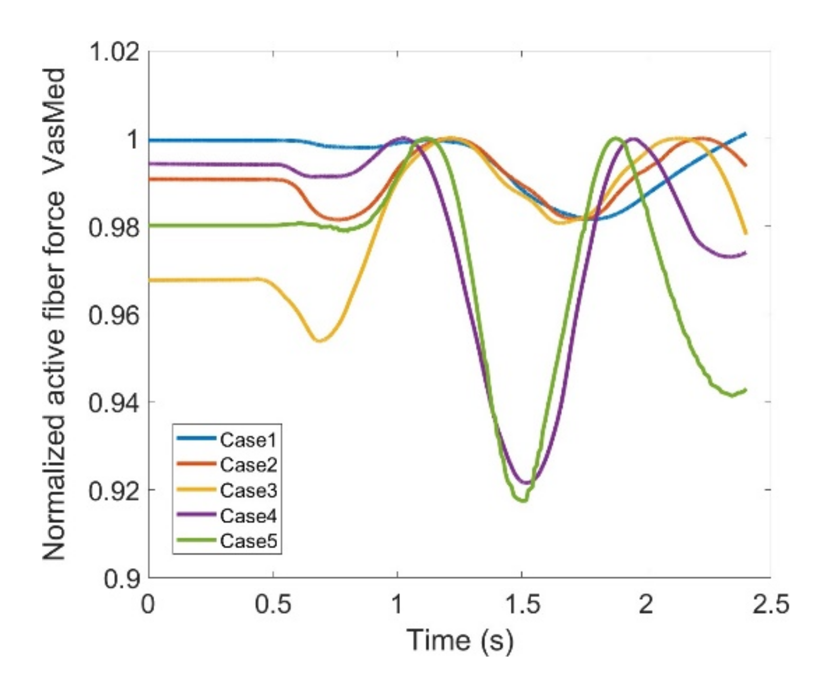
| Vastus Medialis (VM) | 8% |
| Knee Flexor | Differential Range (Normalized) |
| Biceps Femoris-long head (BFLH) | 32% |
| Biceps Femoris-short head (BFSH) | 9% |
| Gracilis (Grac) | 3% |
| Lateral Gastrocnemius (LatGast) | 33% |
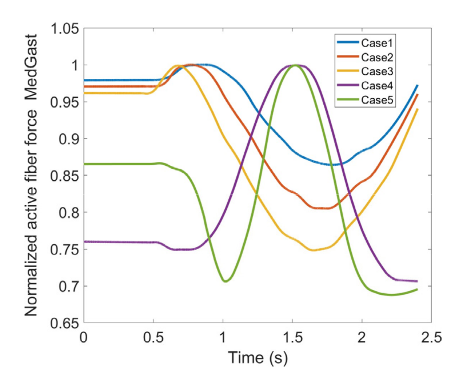
| Medial Gastrocnemius (MedGast) | 31% |
| Sartorius (Sar) | 6% |
| Semimembranosus (Semimem) | 23% |
| Semitendinosus (Semiten) | 22% |
Publisher’s Note: MDPI stays neutral with regard to jurisdictional claims in published maps and institutional affiliations. |
© 2022 by the authors. Licensee MDPI, Basel, Switzerland. This article is an open access article distributed under the terms and conditions of the Creative Commons Attribution (CC BY) license (https://creativecommons.org/licenses/by/4.0/).
Share and Cite
MajidiRad, A.; Yihun, Y.; Hakansson, N.; Mitchell, A. The Effect of Lower Limb Exoskeleton Alignment on Knee Rehabilitation Efficacy. Healthcare 2022, 10, 1291. https://doi.org/10.3390/healthcare10071291
MajidiRad A, Yihun Y, Hakansson N, Mitchell A. The Effect of Lower Limb Exoskeleton Alignment on Knee Rehabilitation Efficacy. Healthcare. 2022; 10(7):1291. https://doi.org/10.3390/healthcare10071291
Chicago/Turabian StyleMajidiRad, AmirHossein, Yimesker Yihun, Nils Hakansson, and Allyson Mitchell. 2022. "The Effect of Lower Limb Exoskeleton Alignment on Knee Rehabilitation Efficacy" Healthcare 10, no. 7: 1291. https://doi.org/10.3390/healthcare10071291