Article

Numerical Simulation of Failure Analysis of Storage Tank with Partition Plate and Structure Optimization

School of Energy and Power Engineering, University of Shanghai for Science and Technology, Shanghai 200093, China
*
Author to whom correspondence should be addressed.
Mathematics 2021, 9(24), 3230; https://doi.org/10.3390/math9243230
Submission received: 21 November 2021 / Revised: 8 December 2021 / Accepted: 10 December 2021 / Published: 14 December 2021
(This article belongs to the Special Issue Numerical Analysis and Optimization: Methods and Applications)

Abstract

:
Storage tanks with partition plates are widely used in the petrochemical industry. However, relevant standards do not propose corresponding design criteria and methods for this type of structure, and theoretical design formulas cannot be applied to ensure the reliability of its structure. Therefore, it is necessary to analyze and design the storage tank with a partition plate by using finite elements. This paper studies the problem of buckling depression and cracks in the welded parts of the S-shaped tank with a partition plate during its operation. We used the finite element software ANSYS to analyze the overall strength and stability of the structure and obtain the larger stress area. Based on this, a safe and economical optimization plan is proposed: under the condition of strictly controlling the liquid level difference on both sides of the partition, the tank structure is optimized by adding stiffeners and tie rods. The study revealed that the measure effectively improves the overall rigidity of the tank body and reduces the maximum stress of the structure and enhances the safety performance of storage tank. Additionally, it provides a reference for the structural strength design of storage tanks with partition plates.

1. Introduction

A storage tank with a partition plate is an atmospheric pressure vessel, which separates the cylindrical shell to form multiple regions to storage different kinds of liquid contents in a single tank [1]. According to the relevant regulations of GB 50160-2018, it is the “Standard for fire prevention design of petrochemical enterprises” [2]. The development of hydrocarbon production in industrial plants and the close distance between these facilities usually lead to the spread of major accidents in the space, which leads to the expansion of the affected area [3,4,5,6]. In order to prevent fire from spreading due to the outflow of combustible liquid materials in case of tank leakage, a certain fire separation distance shall be maintained between adjacent tanks, and fire prevention devices such as fire dike and partition dike shall be set. However, in some cases, especially when the original plant is increased or reconstructed, due to many factors such as plant layout, site constraints, and so on, the storage tank with partition plate is often used to store different materials to meet production requirements. Compared with other types of storage tanks of the same volume, it has the advantages of more centralized overall layout, smaller floor area, easier tank farm management and lower investment cost. Therefore, it is widely used in petroleum, chemical, pharmaceutical, and other, industries [7]. During the normal operation of the storage tank, the liquid level difference on both sides of the partition plate is very small. However, under extreme working conditions, that is, when one side of the partition plate is full of materials and the other side is empty while negative pressure exists, the partition plate will bear a large external pressure, which is likely to cause large displacement of the structure of the partition, resulting in overall strength and stiffness problems, strength and buckling failure, affecting the safe operation of the storage tank and causing economic losses [8,9].
During normal operation of the storage tank with partition plate, due to the small difference in liquid levels on both sides of the partition plate, the force on the partition is small, and its structure is safe. However, under extreme working conditions, that is, when one side of the partition is full of materials and the other side is completely empty and negative pressure exists, the partition needs to withstand greater external pressure, which is likely to cause greater displacement of the partition structure. There will be overall strength and stiffness problems and strength and buckling failure, and other problems will occur, which will affect the safe operation of the storage tank and cause economic losses. As NB/T 47003.1-2009 “Steel welded atmospheric pressure vessels” [10] and AQ 3053-2015 “Safety technical code for vertical cylindrical steel welded tank” [11] and other standards do not put forward the design requirements or contents for the structure of atmospheric vessel with partition plate, it is impossible to use theoretical formulas to design the structure of such vessels and guarantee the reliability. At present, the structural design of the storage tank with a partition plate mainly adopts the finite element analysis method in China. Commonly used methods of increasing wall thickness to ensure safety will also lead to failure and increase in manufacturing costs. Among them, Hong Ying [12] investigated the loaded structure of partition plates with folded plates and S-shaped partition plates for storage tanks and studied the reinforced effect of the tie rod structure. In combination with the design of a water tank, Lu Xi [13] analyzed the structure of the vessel with partition plate, and its characteristics proposed a new type of reinforcing structure combining plates, stiffening ring and strut. Zhu Weibo [14] conducted FEA and experimental study on a large-diameter atmospheric-pressure vessel with a partition plate.
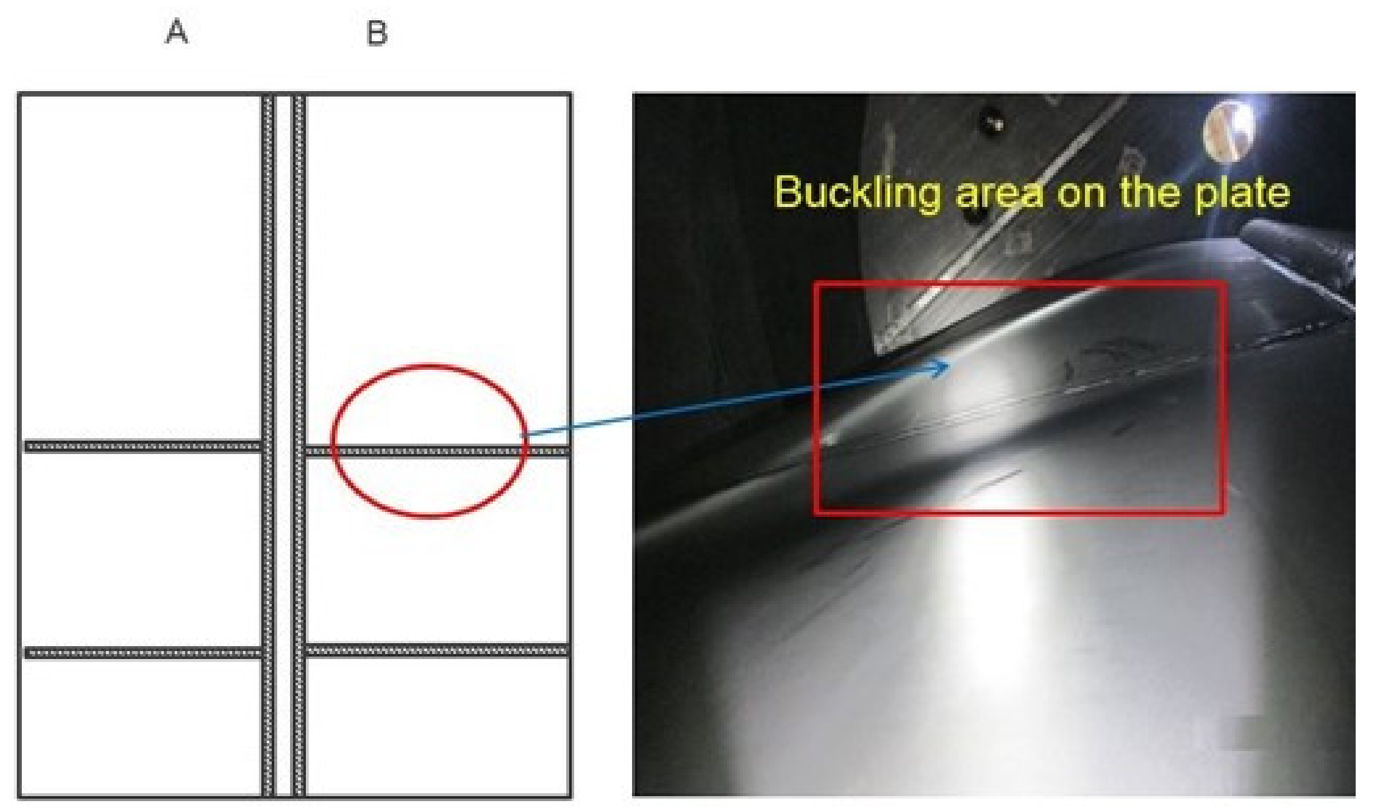
This paper analyzes the problems of the storage tank with S-shaped partition plates that have been in operation in the factory for many years.Problems such as cracks in the welded parts between the partition plate and center vertical columns are shown in Figure 1, and buckling and depression of the partition plate is shown in Figure 2. The strength and stability of the overall model are analyzed with finite element software. According to the analysis based on the numerical model, by adding stiffeners and tie rods, the overall rigidity of the optimized storage tank is significantly improved. At the same time, the improvement measures for the storage tank compartment to operate according to a certain safe operation curve are proposed.

2. Original Model Finite Element Analysis

The model dimensions are based on the original design parameters provided by the factory, and the influences of openings and nozzles on the tank, are ignored. According to process requirements, the inner diameter, height and wall thickness of the tank are 5000 mm and 6000 mm. The wall thickness of the tank is determined in accordance with the formula provided in article 5.3.1 of SH3046-1992 “Petro-chemical design specification for vertical cylindrical steel welded storage tanks”:
t   =   0.0049 ϱ ( H 0.3 ) D [ σ ] t φ + C 1 + C 2
where t is the design thickness when storing the contents, mm; ρ is the density of the storage liquid medium, kg/m3; H is the calculated height of the liquid, m; D is the diameter of the tank cylinder, m; σ t is the allowable stress of the tank wall steel plate at the design temperature, MPa; Φ is the weld coefficient, 0.9; C1 is the negative deviation of the steel plate, mm and C2 is the corrosion allowance, mm. Therefore, the design thickness of the storage tank in this paper is 8 mm, the thickness of bottom plate is 8 mm, the incurvature radius and thickness of S-shaped partition plate are 3300 mm and 8 mm and the outer diameter and wall thickness of the central column are 250 mm and 8 mm. The schematic drawing is shown in Figure 3. The tank is made of stainless steel 304L with excellent corrosion resistance and heat resistance. When the design temperature is 150 °C, the elastic modulus is E   =   1.86   ×   10 5   MPa , the Poisson ratio is 0.3, the allowable stress is 118 MPa, the corrosion allowance is 0 mm and the minus deviation of thickness is 0.3 mm.
The analysis of the straight partition plate of a vertical storage tank can usually be calculated by the theory of the original flat plate of the surrounding fixed branch. However, the storage tank with S-shaped partition plate has a complex structure and many influencing factors, so it cannot be calculated theoretically. Therefore, it is calculated by numerical analysis.
The structural dimensions of the model adopt the original design parameters provided on the drawings of the factory, and the influence of the opening nozzle on the tank body is not considered during the modeling. The upper part of the tank is welded to the head. Since the influence of loaded hydro-static pressure of liquid column on the head is slight, the model is built only for the parts below the head. The mesh of the finite element model is finely divided by the SOLID186 elements. The accuracy of the finite element analysis results is not only related to the correctness of the load and boundary strips, but also to the mesh size and density of the finite element model. It is necessary to verify the mesh independence of the finite element model of the storage tank and the mesh convergence. The results of the analysis are shown in Table 1. When the number of meshes is 15 × 15 mm, and then the meshes are further refined, and the finite element calculation result is only about 1.7% different from that before the refinement. It can be considered that the division accuracy of the model unit meets the calculation requirements. In order to save calculation memory and calculation time, this paper adopts the mesh cell size of 15 × 15 mm to perform finite element analysis on the tank model.
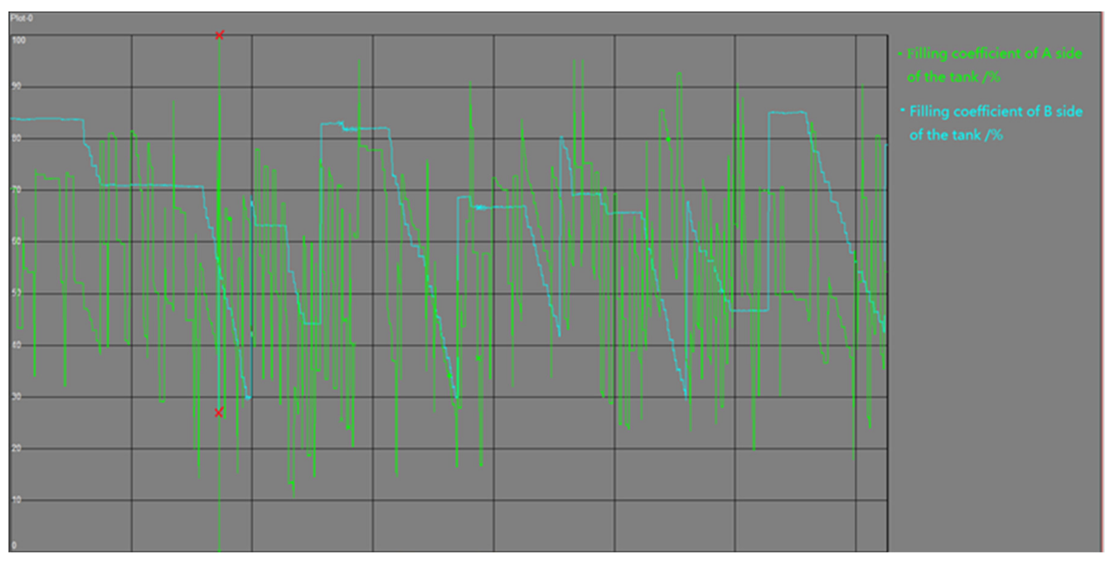
During operation of the storage tank, the liquid height of the contents on both sides of partition plate is fluctuating, and there is a density difference between the contents on both sides of the partition plate. Liquid sloshing refers to the widely existing phenomenon that liquid moves in a container when the tank is subjected to the external excitation, and it will have serious impacts on the security and stability of the system [15,16].The design condition shall be considered for the design of the storage tank, that is, one side of partition plate is fully filled with relatively high-density contents, and the other side is completely empty with negative pressure. Wherein, the distributed load of pressure gradient on the inner surface of one side of the tank caused by the height of the filled liquids can be calculated by
P   =   ϱ gh
where P is the pressure caused by the liquid height of the content, MPa; ρ is the content density, 1.22   ×   10 3   Kg / m 3 and h is the liquid height of the content, mm. The calculation results are shown in Figure 4. The pressure gradient distribution due to the liquid height of 11.956   ×   10 6   MPa / mm and the internal pressure of 6   ×   10 3   MPa are applied to the inner surface of one side of the tank fully filled with content. The negative pressure of 4.9   ×   10 4   MPa is applied to the inner surface of the empty side of the tank. Because the tank is fixed on the foundation, to avoid rigid displacement of the model, the bottom surface of the storage tank is clamped to restrain. When the top of the tank is welded with head, if the reinforcement effect of the head on the tank is considered, the cross-section of the top of the tank is clamped to restrain.

3. Original Model Analysis Results

3.1. Original Model Failure Analysis

The stress and buckling are calculated for the tank model by finite element model, respectively. The calculated stress distribution is shown in Figure 5. It shows that the larger stress areas of the storage tank are mainly on the joints between partition plate and cylindrical shell and the joints between partition plate and central column. The calculated large stress areas are consistent with the areas with cracks. According to the requirement in JB 4732-1995 “Steel Pressure Vessel- Design by Analysis” [17], stress evaluation is required for the large stress area, and it is stipulated that the stress on the evaluation path should satisfy that primary local membrane stress ( P L ) is less than the 1.5 times of the allowable stress ( S m ), and the summation of ( P L ) and secondary bending stress ( P b ) shall be less than three times that of allowable stress ( S m ) [18]. The stress evaluation results are shown in Table 2.
According to the evaluation results in Table 2, the overall strength of the structure is directly affected by such factors as thinner wall thickness of cylindrical shell, smaller diameter and thinner wall thickness of the central column and inner wall, thinner wall thickness of the S-shaped partition plate. The original structural design of the tank cannot meet the allowable stress intensity under the design condition, and its structure is at risk of damage. Therefore, the measures are taken to the tank according to a certain safe operation liquid level curve. The liquid level difference between the two sides of partition plate is shown in Figure 6 after 120 days of operation. The maximum level difference of the original tank under operating condition is that the filling coefficient of contents inside A is 90%, while that inside B is 24%. After operating by curve for a period, it is found that cracks still appeared. Therefore, the maximum liquid level difference between the contents in both sides of tank with partition plate is applied to the finite element model, and the stress distribution is shown in Figure 7. It is seen that the larger stress area is still at the joint between partition plate and the cylindrical shell and the joint between partition plate and the central column. The results of stress evaluation under these condition in this area are shown in Table 3. The results show that the stress of the tank can be reduced by controlling liquid level difference between the contents in both sides of tank with partition plate, but the stress intensity still cannot be met.

3.2. Original Model Buckling Analysis

Because of the thin thickness of the partition plate and large diameter of the tank, when the external pressure load increases to a certain value, the tank may suddenly lose its original shape. After the load is unloaded, the tank cannot return back to its original state and buckling happens, which causes potential safety hazards. Therefore, the buckling analysis of the tank is needed. Eigenvalue buckling analysis is used to study whether the critical load of the tank meets the stiffness requirement under specific load conditions. Under the design condition, the tank is subjected to the combined action of liquid contents static pressure, internal pressure and empty side tank negative pressure. In the eigenvalue buckling analysis, the critical stress of tank under a single load is first determined, and the ratio of stress induced by a single load to critical stress is calculated. Then the sum of all the ratios is obtained. If the ratio is less than 1, buckling will not occur. Based on the linear elastic state analysis of materials, eigenvalue buckling analysis can be used to predict the theoretical buckling value of tank. Generally, a non-conservative result may appear; otherwise, linear buckling has been divided by an eigenvalue safety factor to ensure the reliability of the design. In buckling analysis, eigenvalue critical loads and allowable critical loads are calculated according to Formulas (2) and (3):
P cr = F   ×   λ ,
P m =   P cr / m ,
In Formula (2), P cr is the critical load, MPa; F is the applied load, MPa, and λ is the load factor. In Formula (3), P m is the allowable critical load, MPa, and m is the characteristic buckling safety factor; here, m = 3.
The deformation of the original tank model in eigenvalue buckling analysis is shown in Figure 8. when the static pressure of the liquid contents or the internal pressure of the tank reaches a certain value, the large deformation happens in the middle and lower part of the partition plate, and it is practically consistent with the location of the buckling depression of partition plate in Figure 2. When the negative pressure of the empty side tank is too high, the buckling of the tank will occur firstly. The results of eigenvalue buckling analysis of the original tank model under combined loads are shown in Table 4. The ratio coefficients of the original model under combined loads are 2.128 > 1, which indicates that the original tank structure will buckle under the design condition. The ratio coefficient of static pressure of liquid contents is 1.8, which is the main load leading to the buckling of the partition plate. The liquid level difference between the contents in both sides of the tank with partition plates should be strictly controlled during the operation of the storage tank. The results of FE calculation show that the original tank model cannot meet requirements of strength and buckling under the design condition. It is necessary to redesign or take measures to reduce the deformation and stress of the tank in order to improve the overall stability of the tank and make the tank meet the safety requirements of long-term use.

4. Optimized Model Analysis Results

4.1. Structural Optimization

The original structure design of the tank is unacceptable. Generally, measures such as increasing the thickness of S-shaped partition plate, diameter or thickness of central column can be taken to improve the overall strength and stiffness of the tank. However, this will greatly increase the remanufacturing cost and time. Therefore, based on the original structure of the storage tank, optimization measures including adding stiffeners and tie rods and strictly controlling the liquid level difference between the contents in both sides of the tank with partition plates are put forward. The optimization of tank structure is shown in Figure 9. Since the bottom of the partition plate is stressed, in order to improve the flexural rigidity of the partition plate and reduce the non-spacing support, five S-shaped stiffeners have been added to each convex surface of the S-shaped partition plates from the central column to the single side on the tank wall. The cross-section size is 100 × 10 mm. A tie rod from the central column to the tank wall is added between two adjacent stiffeners on one side of S-shaped partition plate, and its size is 89 × 3.2 mm. Adding a 250 × 250 × 12 mm arc reinforcement plate to the contact position between the tie rod and the central column, a circular reinforcement plate has been added to the contact position between the tie rod and the tank wall. In the FE optimized tank model, the boundary condition are applied according to the design condition mentioned above, and overall stress and buckling of the model are calculated.

4.2. Analysis of Structural Optimization Results

The stress distribution shown in Figure 10, the maximum stress in the tank decreased from 438.05 MPa to 230.56 MPa after the improvement by adding reinforcement bars and tie rods. The larger stress area was still at the joint of partition plate with the tank and the joint of partition plate with the central column. The results of stress evaluation are shown in Table 5, which shows that the structural optimization can effectively reduce the stress of the tank. The results of eigenvalue buckling analysis of the improved model are shown in Table 6. Under extreme condition, the ratio coefficient of each load is 0.886 < 1. It shows that the stiffeners and tie rods can improve the overall stiffness of partition plate, reduce its maximum deformation and satisfy the safety of the storage tank under the design condition. Liquid level controllers are installed in both sides of partition plate in the optimized tank to make sure the liquid difference is not too big. The liquid level differences measured in the optimized storage tank for 203 days is shown in Figure 11. The maximum level difference under operating condition is that the filling coefficient of contents inside A is 100%, while that inside B is 27%. The FE structural optimization model is carried out under the operating condition at the maximum liquid level difference, and its results are shown in Table 7. The comparison between the stress of the improved model under the design and that of maximum operating condition has been shown in Figure 12. The comparison shows that the strength, stiffness and stability of the improved tank under the design condition can be met through structural optimization.

4.3. Stress Analysis of Partition Plate

In order to study the stress state of the S-shaped partition plate in the original and the optimized models, three paths are defined respectively from the connection between the partition plate and the tank, the center of partition plate and the connection between partition plate and the central column, which are shown in Figure 13. The Von Mises stress values of the nodes in each path of the original model and the optimized model under maximum operating condition are output. The results are shown in Figure 14, from which we can see that the trend of stress magnitude of nodes along the Z direction is consistent in the same model and the same path. The stress state of partition plate is large at both ends and small in the middle, and the maximum stress value is at the height of 0–1000 mm at the bottom. Compared with the original model, the optimized model has a better stress state, and the optimized model under operating condition has the best stress state. The results show that the structure of the tank can be optimized without increasing the wall thickness of partition plate, which provides a reference for the structural design and optimization of similar tanks with partition plates.

5. Conclusions

In this paper, the leakage in storage tank with an S-shaped partition plate is studied using a finite element model. A structure combing stiffeners and rods are added to optimize the design of a leaked storage tank with S-shaped partition plates. There are the following conclusions:
  • The results of stress analysis of pressure vessels with bulkhead storage tanks are closely related to the difference in liquid level on both sides of the partition plate. In the design process of this type of vessels, it is very necessary to perform finite element analysis on the extreme conditions where one side of the partition is full of materials and the other side is completely empty and negative pressure exists.
  • For storage tank with an S-shaped partition plate, because the bottom is greatly affected by the liquid column pressure, the larger stress areas are mainly located in the weld of the partition plate and tank and the weld of the partition plate and central column, which are the main dangerous areas. Under maximum operating, strength failure may occur at the joint of tank bottom, while buckling failure may occur at partition plate.
  • The use of structural optimization measures that combine reinforcing stiffness and tie rods structures has the advantage of effectively improving the overall strength and rigidity of the storage tank, making the stress distribution more reasonable. The addition of a liquid level controller to strictly control the liquid level difference in both sides of the partition can further improve the stress state of the structure. Under the design condition, P L decreased by 18.1% in area 1, 33.6% in area 2 and 19.6% in area 3, ensuring the safe and effective operation of the equipment.

Author Contributions

Methodology, X.F.; software, X.F.; writing—original draft preparation, X.F.; writing—review and editing, W.S.; funding acquisition, W.S. All authors have read and agreed to the published version of the manuscript.

Funding

This work received no external funding.

Institutional Review Board Statement

Not applicable.

Informed Consent Statement

Not applicable.

Data Availability Statement

Not applicable.

Acknowledgments

The authors would like to thank the referees for helpful comments to improve the original paper and Covestro Polymers (China) Co., Ltd. for supporting this project (Project name: MEKO storage tank & BL3175SN storage tank).

Conflicts of Interest

The authors declare no conflict of interest.

References

  1. Su, W.; Wu, X. Structure analysis and design of vertical storage tank with clapboard. Mech. Eng. Automation. 2015, 191, 110–112. [Google Scholar]
  2. Ministry of Housing and Urban-Rural Development of the People’s Republic of China. GB 50160-2018 Standard for Fire Prevention Design of Petrochemical Enterprises; China Planning Press: Beijing, China, 2018; pp. 6–16.
  3. Zhang, M.; Zheng, F.; Chen, F.; Pan, W.; Mo, S. Propagation probability of domino effect based on analysis of accident chain in storage tank area. J. Loss Prev. Process Ind. 2019, 62, 215–228. [Google Scholar] [CrossRef]
  4. Meriem, S.; Mebarek, D.; Leila, L. Proposal for a new method for analyzing the domino effect in an oil refinery and its impact. Manag. Environ. Qual. 2019, 30, 910–923. [Google Scholar]
  5. McGee, S.; Frittman, J.; Ahn, S.; Murray, S. Implications of cascading effects for the Hyogo framework. Int. J. Disaster Resil. Built Environ. 2016, 7, 144–157. [Google Scholar] [CrossRef]
  6. Abdolhamidzadeh, B.; Abbasi, T.; Rashtchian, D.; Abbasi, S. Domino effect in process-industry accidents—An inventory of past events and identification of some patterns. J. Loss Prev. Process Ind. 2011, 24, 575–593. [Google Scholar] [CrossRef]
  7. Gao, B.; Zhao, J.; Wang, J. Stress analysis of circular cross-section pressure vessel with clapboard. Mech. Eng. Autom. 2000, 29, 21–22. [Google Scholar]
  8. Cui, C. Structural analysis and design of vertical storage tank with vertical partitioning plate. Process Equip. Pip. 2019, 56, 10–13. [Google Scholar]
  9. Li, C.; Fu, Q. Discussion on design technology of storage tank structure in petrochemical plant. Mod. Chem. Res. 2019, 3, 46–47. [Google Scholar]
  10. National Energy Board. NB/T 47003.1-2009 Steel Welded Atmospheric Pressure Vessels; Xinhua Publishing House: Beijing, China, 2010; pp. 4–74. [Google Scholar]
  11. Ministry of Emergency Management of the People’s Republic of China. AQ 3053-2015 Safety Technical Code for Vertical Cylindrical Steel Welded Tank; China Coal Industry Press: Beijing, China, 2015; pp. 3–14.
  12. Hong, Y.; Jing, S.; Wang, H. Application of rod structure in tanks. Press. Vessel Technol. 2008, 25, 16–20. [Google Scholar]
  13. Lu, X.; Wang, F.; Chen, Y. Analysis and design of atmospheric pressure cylindrical vessel with clapboard. J. Mech. Strength 2004, 26, 460–462. [Google Scholar]
  14. Zhu, W.; Liu, F.; Lin, X. Structure analysis and experiment study of atmospheric-pressure large-diameter vessel with compartment plates. Press. Vessel Technol. 2003, 20, 5–7. [Google Scholar]
  15. Hang, G.; Zhao, Y.; Jun, L.; Quan, S. Finite element method for analyzing effects of porous baffle on liquid sloshing in the two-dimensional tanks. Eng. Comput. 2020, 38, 2105–2136. [Google Scholar]
  16. Liu, P. Process System Design of atmospheric pressure liquid chemical storage tank. Chem. Eng. Des. 1999, 9, 22–25. [Google Scholar]
  17. Ministry of Machinery Industry of the People’s Republic of China. JB 4732-1995 Steel Pressure Vessel-Design by Analysis; China Machinery Industry Press: Beijing, China, 1995; pp. 17–20.
  18. Sun, H.; Li, H.; Qian, F. Stress analysis and strength assessment of ammonia water storage tank. IOP Conf. Ser. Mater. Sci. Eng. 2019, 504, 012007. [Google Scholar] [CrossRef]
Figure 1. Cracks in the welded joints between center column and partition plate (A is the left side of the tank partition plate, B is the right side of the tank partition plate).
Mathematics 09 03230 g001
Figure 2. Buckling and depression area of the partition plate (A is the left side of the tank partition plate, B is the right side of the tank partition plate).
Mathematics 09 03230 g002
Figure 3. Storage tank with S-shaped partition plate.
Mathematics 09 03230 g003
Figure 4. The results of the pressure gradient.
Mathematics 09 03230 g004
Figure 5. Area with large stress.
Mathematics 09 03230 g005
Figure 6. Material filling factor of the original tank model under operating condition.
Mathematics 09 03230 g006
Figure 7. Stress of the original tank model under maximum operating condition.
Mathematics 09 03230 g007
Figure 8. Buckling deformation distribution of the original tank: (a) Buckling deformation caused by static pressure of liquid contents, (b) Buckling deformation caused by internal pressure, (c) Buckling deformation caused by negative pressure.
Mathematics 09 03230 g008
Figure 9. Structural optimization method.
Mathematics 09 03230 g009
Figure 10. Stress distribution of the structural optimization model under design condition.
Mathematics 09 03230 g010
Figure 11. Material filling factor of the structural optimization model under maximum operating condition.
Mathematics 09 03230 g011
Figure 12. Comparison of stress evaluation results before and after model optimization under (a) the design condition and (b) the maximum operating condition.
Mathematics 09 03230 g012
Figure 13. Stress path of partition plate.
Mathematics 09 03230 g013
Figure 14. The relevance between Von Mises stress and Z-direction height of partition plate (a) Comparisons of path 1, (b) Comparisons of path 2, (c) Comparisons of path 3.
Mathematics 09 03230 g014aMathematics 09 03230 g014b
Table 1. Mesh convergence results.
Mesh Size (mm)Maximum Stress (MPa)Deviation
50 × 50519.1518.5%
25 × 25450.762.9%
15 × 15438.05datum
10 × 10430.61.7%
Table 2. Stress evaluation results of the original model under design condition.
Stress Evaluation Area P L   ( MPa ) ( P L + P b )
( MPa )
S m   ( MPa ) Stress EvaluationResults
1200.2238.4118 P L   >   1.5 S m failed
2256.4280.2118 P L   >   1.5 S m failed
3212.4250.6118 P L   >   1.5 S m failed
Table 3. Stress evaluation of the original tank model under maximum operating condition.
Stress Evaluation Area P L   ( MPa ) ( P L + P b )
( MPa )
S m   ( MPa ) Stress EvaluationResults
1187.3200.9118 P L   >   1.5 S m failed
2211.5231.4118 P L   >   1.5 S m failed
3197.2225.3118 P L   >   1.5 S m failed
Table 4. The results of eigenvalue buckling analysis of the original tank model.
ClassificationLoad 1Load 2Load 3
internal pressure (MPa)0.006//
negative pressure (MPa)/−0.00049/
material density ( Kg / m 3 ) //1.22 × 103
unit load111
unit load factor0.0610.0522.033
eigenvalue critical load (MPa)0.061−0.0522.033
permissible critical load (MPa)0.02−0.0170.678
λ i 0.30.0291.8
λ i 2.128
Table 5. Stress evaluation results of the structural optimization model.
Stress Evaluation Area P L   ( MPa ) ( P L + P b )
( MPa )
S m   ( MPa ) Stress EvaluationResults
1164.2168.0118 P L   <   1.5 S m
P L + P b   <   3 S m
qualified
2170.5185.2118 P L   <   1.5 S m
P L + P b   <   3 S m
qualified
3171.9202.3118 P L   <   1.5 S m
P L + P b   <   3 S m
qualified
Table 6. The results of eigenvalue buckling analysis of the original tank model.
ClassificationLoad 1Load 2Load 3
internal pressure (MPa)0.006//
negative pressure (MPa)/−0.00049/
material density ( Kg / m 3 ) //1.22 × 103
unit load111
unit load factor0.0950.0285.681
eigenvalue critical load (MPa)0.095−0.0285.681
permissible critical load (MPa)0.032−0.0091.894
λ i 0.1880.0540.644
λ i 0.886
Table 7. Stress evaluation results of the structural optimization model under maximum operating condition.
Stress Evaluation Area P L   ( MPa ) ( P L + P b )
( MPa )
S m   ( MPa ) Stress EvaluationResults
1154.3157.4118 P L   <   1.5 S m
P L + P b   <   3 S m
qualified
2162.3175.3118 P L   <   1.5 S m
P L + P b   <   3 S m
qualified
3160.6188.8118 P L   <   1.5 S m
P L + P b   <   3 S m
qualified
Publisher’s Note: MDPI stays neutral with regard to jurisdictional claims in published maps and institutional affiliations.

