1. Introduction
The heart-lung machine has been used in open-heart surgery for over 60 years. The use of artificial blood circulation marked the beginning of an era of modern cardiac surgery, as it became possible to stop the heart and perform open-heart surgery. The function of this device is to pump the patient’s blood and saturate it with oxygen. It is important to maintain a stable temperature of oxygenated blood or cardioplegia solution during a cardiopulmonary bypass (CPB) surgery. For this, heat exchangers are used. Body temperature is reduced by cooling the blood in a heat exchanger to reduce tissue oxygen consumption and thus protect organs from hypoxia. In a heat exchanger, blood is heated or cooled by the heat exchange between the blood and the water [
1,
2]. The heat exchanger is also used in the extracorporeal membrane oxygenation ECMO circuit for a cardiopulmonary support procedure to cool and warm the blood [
3].
Blood is drawn from the patient’s venae cavae through venous cannulas and is drained by wide-diameter tubes into a reservoir. Blood is drawn from the venous reservoir using a pump and is pushed through a membrane oxygenator, which acts as a lung, after which the blood enters a heat exchanger, which lowers the temperature of the blood. The blood then passes through the arterial filter and returns to the aorta or peripheral artery through the arterial cannula [
2]. It is important to closely control the hypothermia level of perfusion so that the body temperature can be safely kept at a very low level (deep hypothermia). At such body temperatures, blood flow to the whole body can be safely interrupted to allow for certain surgical procedures that were previously considered impossible [
4,
5,
6,
7].
Computer modelling is increasingly being used in the design and manufacture of medical devices. Modelling helps reduce the time and cost of researching ideas, developing and refining designs, and developing and testing prototypes. Another important advantage of modelling is the high accuracy in assessing the functionality of the device. Model-based heat exchanger design and optimization is an efficient tool, as it requires fewer resources compared to other design methods. MSC Easy5 is a dynamic modelling software [
8]. This software allows designers to model control systems, mechanical, electrical, hydraulic and many other systems. MSC Easy5 as a tool for modelling and controlling the Air Conditioning systems’ multichannel heat exchanger model that was used in [
9]. Dynamic heat exchanger models are analyzed in [
10,
11]. However, modeling of the heat exchanger used in the cardiopulmonary bypass (CPB) machine has not yet been performed.
Computational modelling using MSC Easy 5 and application of the necessary functional blocks allows for the creation of a full-fledged virtual prototype of a temperature control device in a heat exchanger and the conduction of virtual tests of the developed device at the design stage. The model helps to identify the shortcomings of both mechanical and electronic control systems, as well as make the necessary decisions before producing a real prototype of the product.
The purpose of this work is to create a concept and model of a temperature control circuit using the MSC Easy5 system, creating mathematical models of blocks of the temperature control circuit, and describing the principle of temperature control in the artificial circulation circuit.
2. Materials and Methods
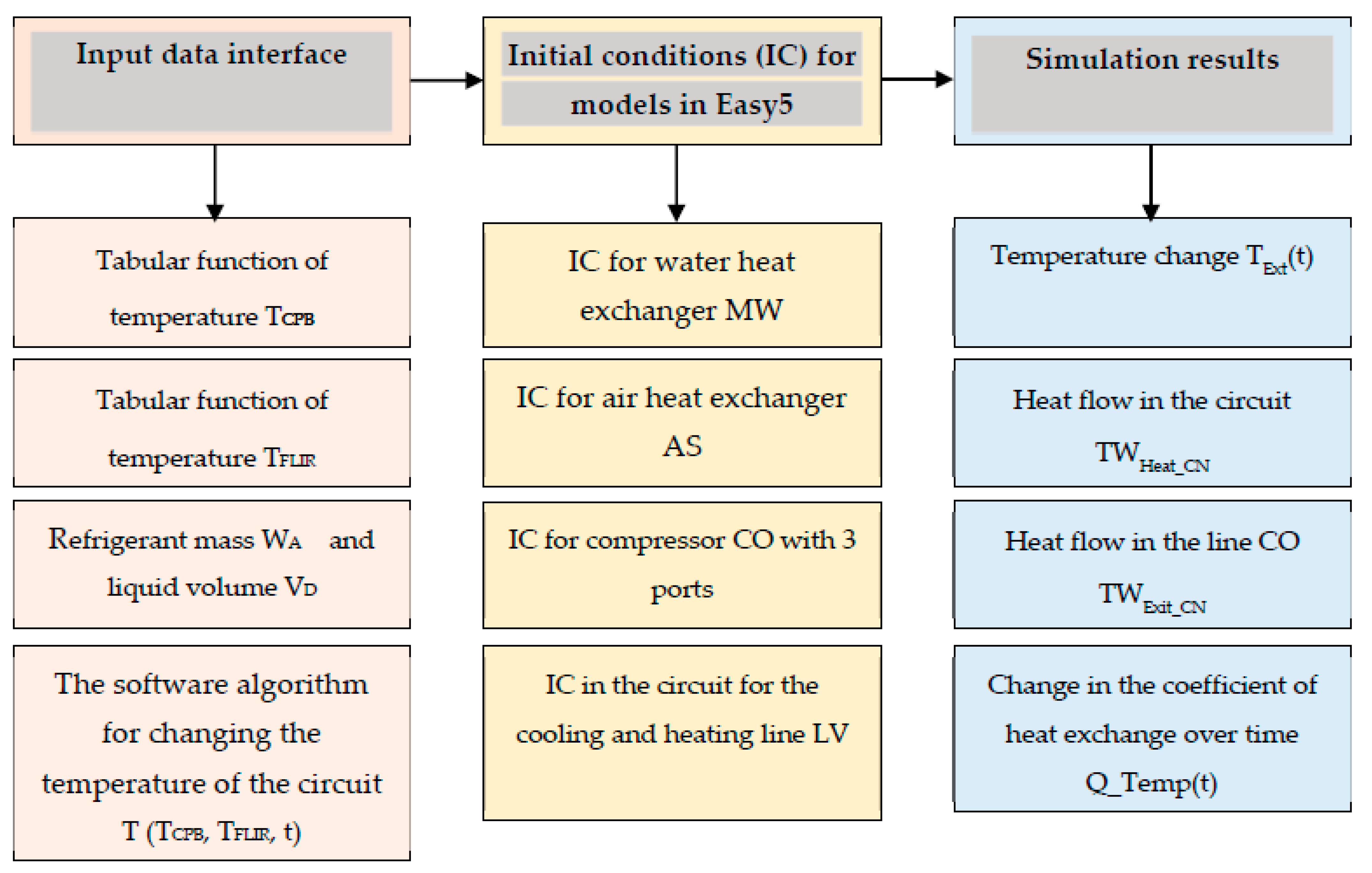
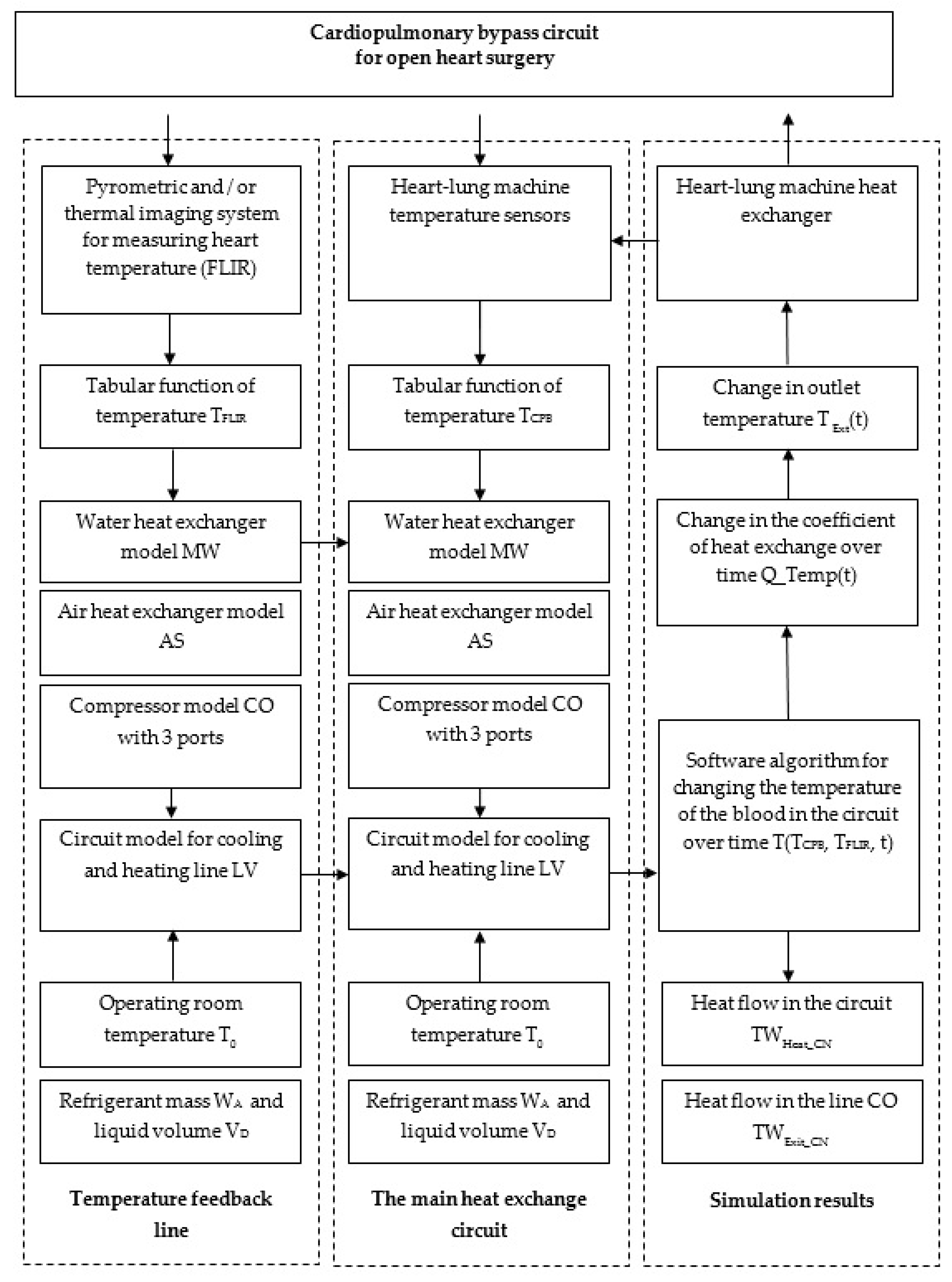
Use of the MSC Easy5 system for modelling the temperature control scheme of the heart-lung machine’s heat exchanger contains input data using the interface, determines the initial conditions for mathematical models and obtains initial modelling data. Mathematical models in the MSC Easy5 system are implemented for the heart-lung machine‘s heat exchanger in the form of a temperature control circuit in the heart-lung machine with a temperature control accuracy of ±1 °C. The concept of using the MSC Easy5 system to simulate the temperature control circuit in a heat exchanger is shown in
Figure 1.
Automation of the temperature control process in the CPB circuit provides for the following stages of creating an information system: selection of an automatic control system, e.g., a single-circuit automatic temperature control system; selection of a typical control process, for example, a model of proportional control of the refrigerant temperature T(t, P) in the system depending on the direction of liquid flow and variable pressure of the liquid P(t) in the circuit; creating a functional diagram of a heat transfer control system, for example, in the MSC Easy5 system for modelling and describing mathematical models of a temperature control circuit; and formalization of a control algorithm, for example, a program for a microprocessor system, in which a specialized temperature control algorithm is implemented.
A complete functional model of the temperature regulation and control system in the heat exchanger of the heart-lung machine, therefore, includes the implementation of an interface for controlling input data, an automatic temperature control system, a system for monitoring fluid pressure and regulating heat transfer in the heat exchange loop, and a software temperature control algorithm. The developed functional model in the MSC Easy5 system can significantly reduce economic costs in the production of heat exchangers for heart-lung machines and reduce the cost of their maintenance.
2.1. Functional Circuit for Temperature Control in the Heat Exchanger
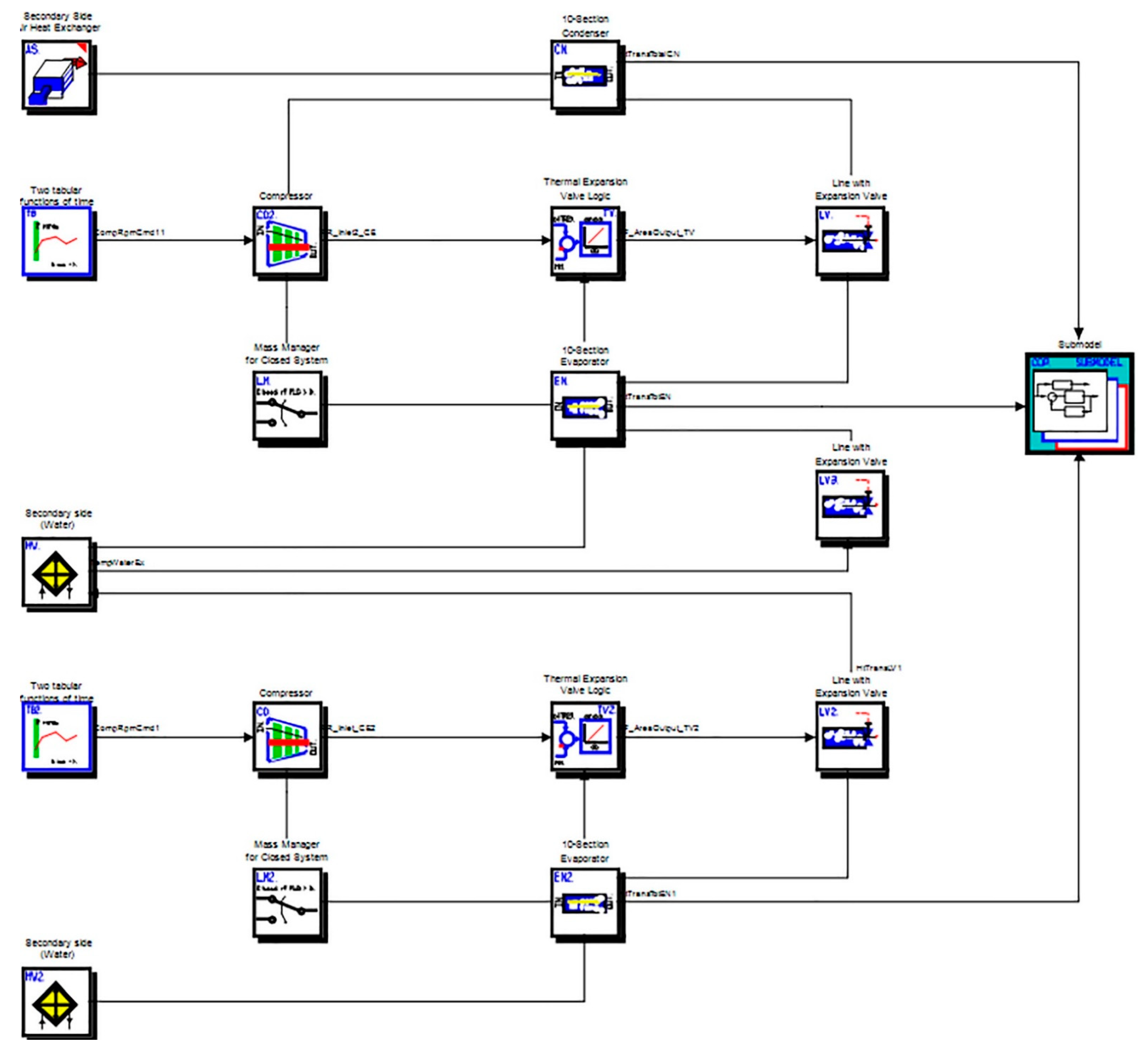
The model of the functional diagram of temperature control in the heart-lung machine’s heat exchanger, which is implemented in the MSC Easy5 system, is shown in
Figure 2.
The mathematical model showing the block of the water section of the heat exchanger is presented in the form of a thin-walled pipe through which cooled or heated water flows. This simulates the thermal process in a liquid heat exchanger. The model takes into account the temperature of the core (water) and, using stationary approximations of heat transfer, allows the rate of heat transfer in the core to be calculated. The wall temperature is assumed constant along the entire length of the pipe in which there is no pressure drop.
In the implemented model, the temperature control circuit includes the following functional blocks (
Table 1).
The mathematical description of the models of device prototypes implemented in the temperature control circuit in the heat exchanger includes the equations of heat exchange and heat transfer [
12,
13,
14,
15,
16] for the mathematical models of functional blocks used in the MSC Easy5 system: mathematical model of the heat exchanger water section unit, mathematical model of the heat exchanger air unit, mathematical model of the thermal expansion valve regulator unit, mathematical model of the cooling and heating line with a valve on the pipe and CN and EN (condenser and evaporator components (CN & EN)) mathematical models of the refrigerant condensation unit in the system.
Below is an example of a mathematical model of a heat exchanger water section block.
2.2. Description of the Mathematical Model of the Heat Exchanger Water Section Block
The functional view of the block of the water section of the heat exchanger is shown in
Figure 3.
To calculate the heat transfer in the block of the heat exchanger’s water section, the amount of incoming heat
is taken into account: this is the temperature of the exchanger core. Average air temperature (
) for heat exchange purposes is:
and heat transfer
. Output temperature derivative:
.
The maximum amount of heat that could be transferred is . The pressure drop along the entire length of the pipe is constant 2 = 1.
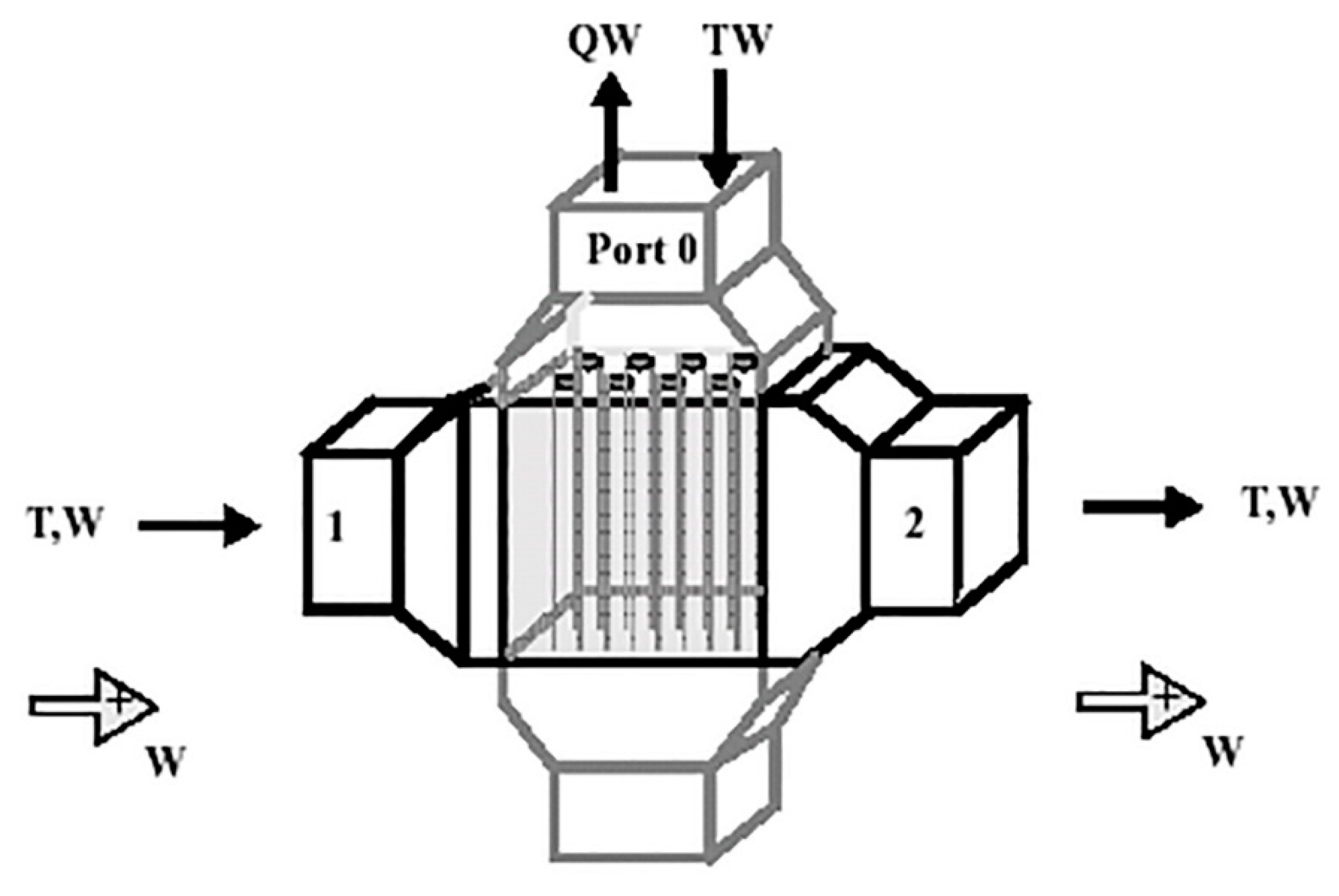
The mathematical model of a compressor block with three inlet and exit ports, which describes the law of conservation of mass and energy for a fluid flow in a multisection chamber, is shown in
Figure 4.
The description of the model of the compressor block includes the following elements of the mathematical model: fluid flow (conservation of mass and energy [
17]) in the intake chamber and the inner chamber of the compressor and changes in the temperature of the compressor casing.
Conservation of fluid mass for the inlet chamber is represented by the equation:
Conservation of the mass of liquid for the exit chamber is:
Energy conservation equation (first law) for the inlet chamber is:
Energy conservation equations for the exit chamber are:
where
QW—it is work on the liquid by compressing and adding energy due to imperfect compressor behaviour;
QCSI and
QCSX—heat transfer rates to the compressor casing;
u—specific internal energy of liquid (
);
V—is the control volume,
—the density of the control volume.
Combining the equations of mass and energy for the input expressions, we find the rate of change of pressure and enthalpy in the inlet chamber:
Likewise for the exit chamber: and .
Internal compressor flow rate
and the output flow
defined as:
—volumetric efficiency.
The total work performed by the compressor on the liquid is:
is isentropic efficiency.
is entropy of fluid in the inlet chamber
The general power:
where
is overall mechanical efficiency.
The energy transferred from the carrier to the compressor housing approaches the value.
and the energy spent on the environment:
The rate of change in the temperature of the compressor housing is:
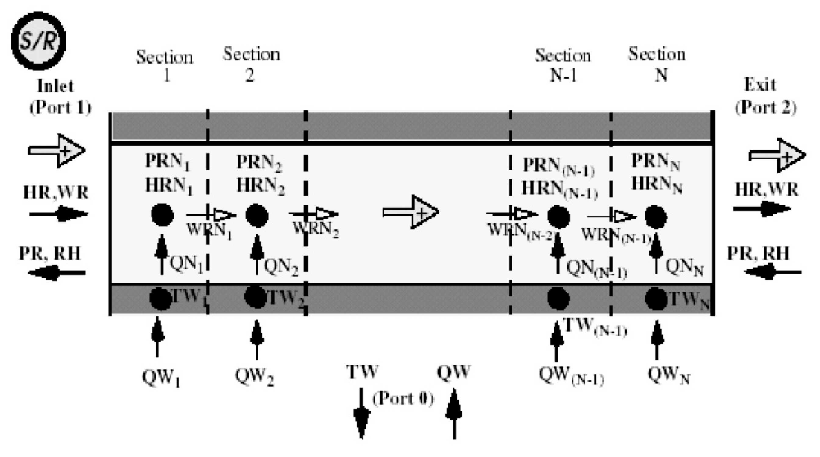
On the basis of the presented mathematical model with the use of a compressor block to understand the processes of cooling and heating in a pipe (
Figure 4), it is possible to formulate a one-section mathematical model for a cooling and heating line. According to this model, the conservation of mass and energy of the refrigerant is described by differential equations for pressure (
PRInlet) and enthalpy (
HRExit) in a separate section of the circuit:
and
where
—heat that is transferred from the pipe wall to the liquid,
—fluid temperature in the circuit,
—pipe volume,
—pipe wall surface area.
Accordingly, the initial total mass flow through the loop sections is:
where
—enthalpy at the inlet and exit of the section,
—output mass flow at the section inlet.
The wall temperature for a single-section cooling and heating line is defined as:
where
, MCW—specific heat capacity (or massic heat capacity) of the wall.
Therefore, a one-section mathematical model of a cooling and heating line in a pipe makes it possible to take into account the heat flux through the pipeline wall in the process of analyzing the system. For example, such a mathematical model fully describes the operation of the LV component in the MSC Easy5 system (
Table 1), provided that the total mass of refrigerant in the system is maintained at a user-specified value.
2.3. The Principle of Temperature Control in the Cardiopulmonary Bypass Circuit
The principle of temperature control in the cardiopulmonary bypass circuit, based on the developed model of temperature control in the heat exchanger, allows for the implementation of a feedback line. It allows the open heart temperature to be used to regulate the temperature while the refrigerant is cooled and heated in the heat exchanger.
The MSC Easy5 system facilitates the creation of function blocks to simulate the operation of programmable microcontrollers that use the C or Fortran language. This makes it possible to investigate the functionality of the developed temperature control algorithm.
The created virtual prototype of the temperature control system allows for improvements to the heat exchanger design, such as heat exchange efficiency (to increase the heat transfer coefficient and the average temperature difference between the blood and the refrigerant) and the heat transfer mode (thermal conductivity and convection heat transfer).
The use of a temperature feedback line and a temperature control software algorithm made it possible to improve the functionality of a heat exchanger for a heart-lung machine. Thus, the block diagram of the temperature control system in the heart-lung machine’s heat exchanger has the form shown in
Figure 5.
The block diagram of the temperature control system in the heat exchanger of the heart-lung machine contains the following main elements for temperature control and management:
Technical systems for measuring and controlling temperature: a pyrometric or thermal imaging system for measuring heart temperature, temperature sensors of the heart-lung machine, the heat exchanger of the heart-lung machine.
Mathematical models of blocks of the temperature control circuit: model of water heat exchanger MW, model of air heat exchanger AS, model of CO compressor with three states, circuit model for cooling and heating line LV
Software module for temperature control: an algorithm for controlling the change in blood temperature in the heat exchange circuit, a module for visualizing simulation data and simulating processor time.
The block diagram (
Figure 5) of the temperature control system in the heart-lung machine’s heat exchanger allows the following indicators to be automatically calculated in time:
Heat flow in the heat exchange loop TWHeat_CN [W·m−2]
Heat flow in the feedback line TWExit_CN [W·m−2]
Coefficient of heat exchange in time Q_TempExit(t) [W/(m2·°C)]
Exit temperature in the heat exchange circuit TExt(t) [°C]
Calculation and control of these indicators in time allows for the optimization of the parameters of the functioning of the developed system for temperature control in the heat exchanger of the heart-lung machine in various modes of its operation. The result of computer modeling of the system is to obtain optimal parameters and solutions that correspond to the real operating conditions of a heat exchanger for a heart-lung machine.
3. Using IR Thermography to Experimentally Check the Temperature Distribution of a Heat Exchanger
The simulation results of the temperature control circuit in the heat exchanger are presented in
Figure 6,
Figure 7,
Figure 8,
Figure 9,
Figure 10 and
Figure 11 for the input data, intermediate results in the system blocks and the simulation output data, respectively:
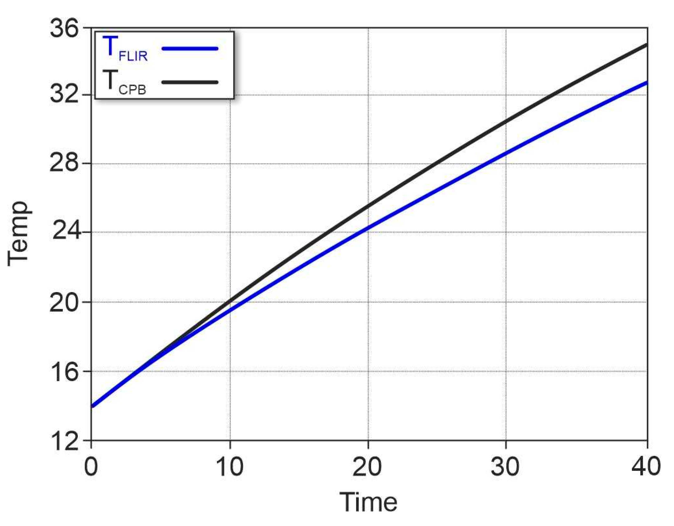
Monitoring the temperature in the patient’s esophagus and the temperature with the FLIR camera on the myocardial surface demonstrates a significant difference in the indication of the heart-lung machine sensor system and the thermal field on the myocardial surface up to 4 °C, which confirms the need to implement a temperature control scheme for the heat exchanger of the heart-lung machine. This temperature control scheme, which is modeled in the MSC Easy5 system for temperature control in the heat exchanger (
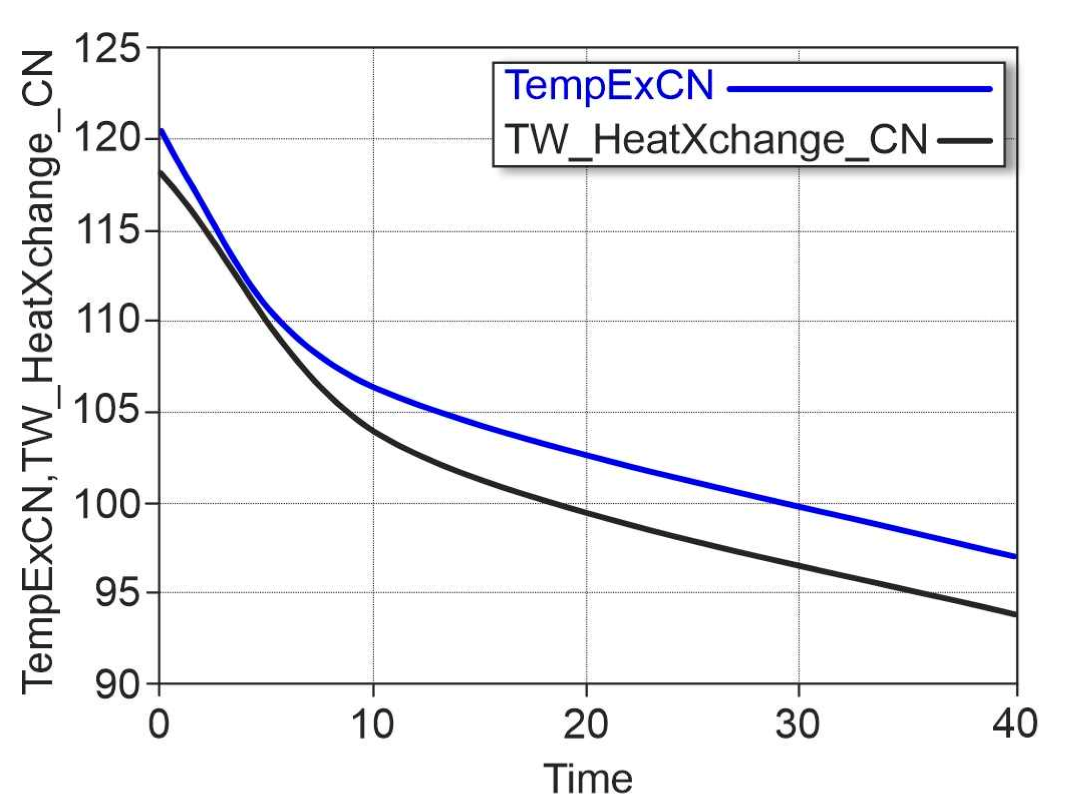
Figure 5), automatically calculates the change in heat flow in the system circuit (TW_HeatXchange_CN, TempExCN) and the blood circulation circuit (QTotRemoved_
S, QTotRemoved _
L). The results for these parameters are presented by heat flow diagrams in the form of CN and EN models over time (
Figure 7,
Figure 8,
Figure 9 and
Figure 10).
- 2.
Calculated data for heat flux and temperature, which are calculated by functional blocks in the process of simulating the operation of the temperature control system:
The maximum temperature difference between the indications of the heart lung machine temperature control system and the FLIR thermographic system is observed in the range of changes in the heat flux in the system circuit (TW_HeatXchange_CN) and the feedback line (TempExCN) from 90 to 105 W/m, which corresponds to a time interval of 10–40 min, with the total duration of the hyperthermia process being up to 50 min. This time interval corresponds to the transition process from a cooled to a warmed heart, in which the greatest temperature difference is recorded in the heart lung machine circuit in the patient’s esophagus. Thus, the simulation of the heat flow in the heat exchanger for the heart lung machine system and the feedback line during blood warming gives a result that corresponds to the real data on the change in myocardial temperature during cardiopulmonary bypass.
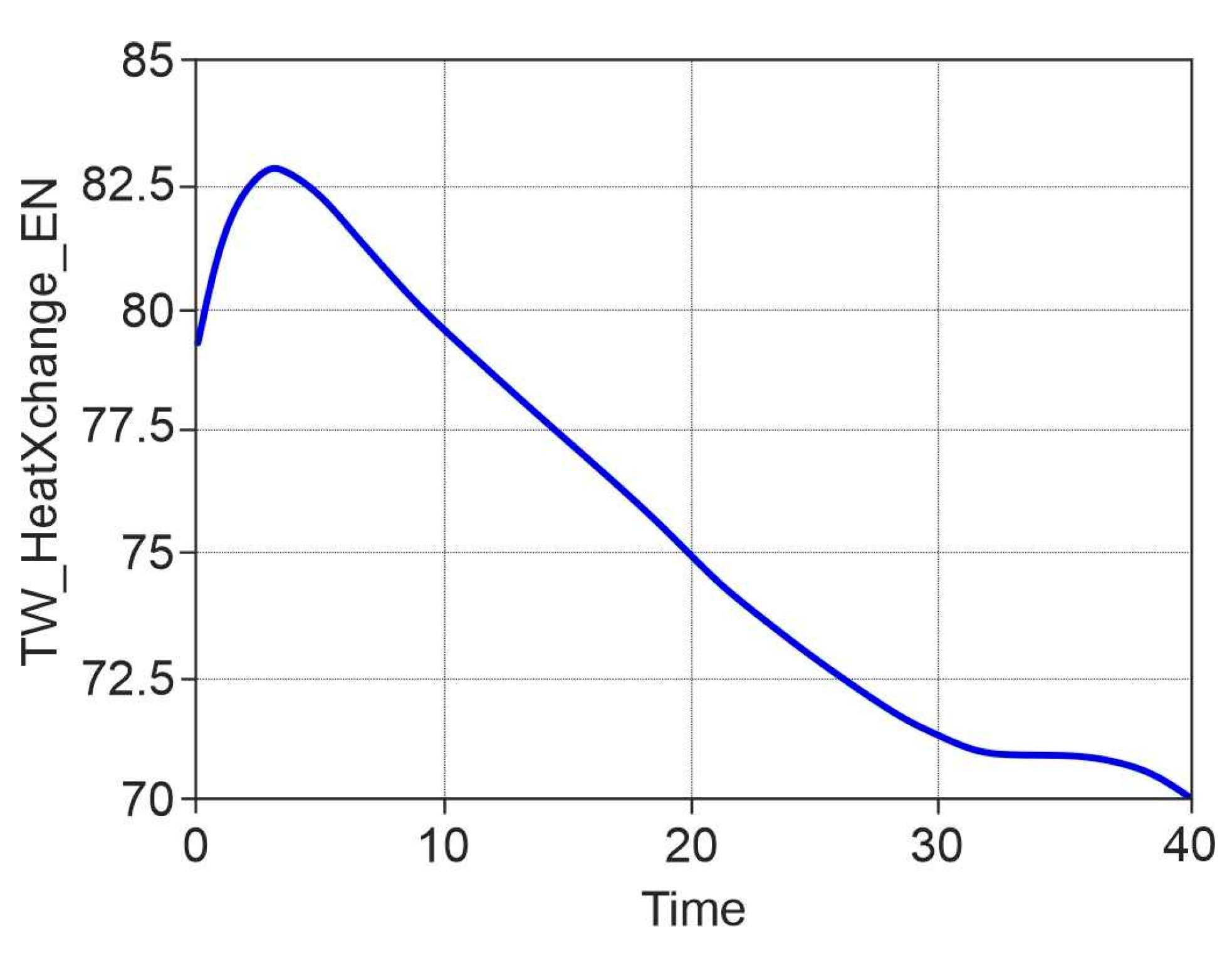
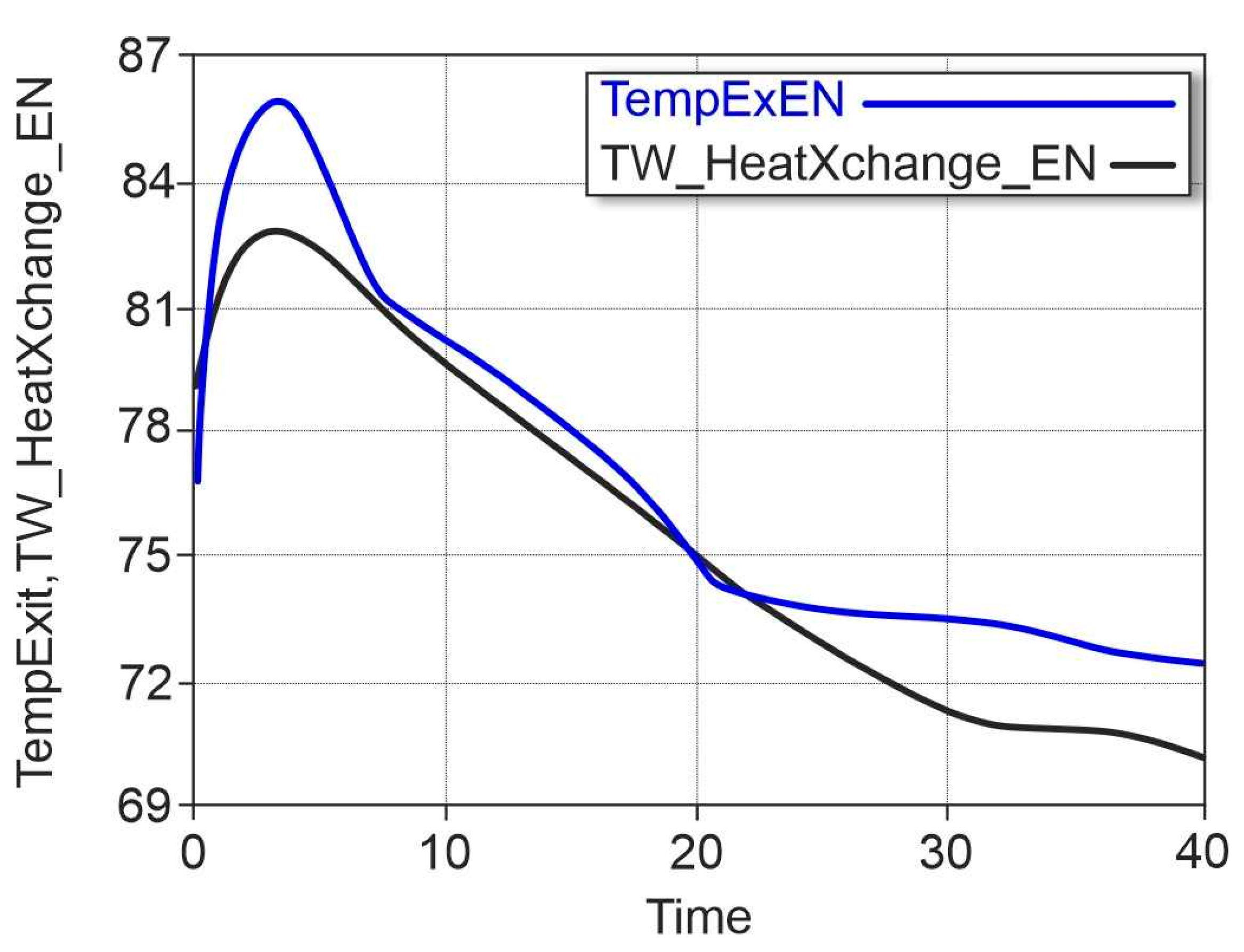
The EN model in time for warming blood at the heart lung machine outlet shows that the change in heat flow in the system circuit (TW_HeatXchange_EN) is an inertial and slow process in time, which depends only on the condensation of the refrigerant in the heat exchanger over time. This allows the implementation of a temperature control system for the feedback line, which should minimize the heat flux gradient in the system loop (TW_HeatXchange_EN) and in the feedback line (TempExitEN).
The use of the temperature control scheme for the heat exchanger of the heart-lung machine allows for the minimizing of the heat flux gradient in the system circuit (TW_HeatXchange_EN) and in the feedback line (TempExitEN) when the blood is warmed up to 1 W/m with a hyperthermia process duration of 20 min. and reduce the heat flux gradient to 12 W/m with the duration of cardiopulmonary bypass up to 40 min.
Temperature control in the heart-lung machine circuit maintains a minimum temperature difference in the machine circuit in the patient’s esophagus up to 1 °C, which corresponds to a temperature measurement accuracy of ±0.5 °C in the esophagus or on the myocardial surface, which is sufficient to ensure the temperature safety of the heart-lung machine.
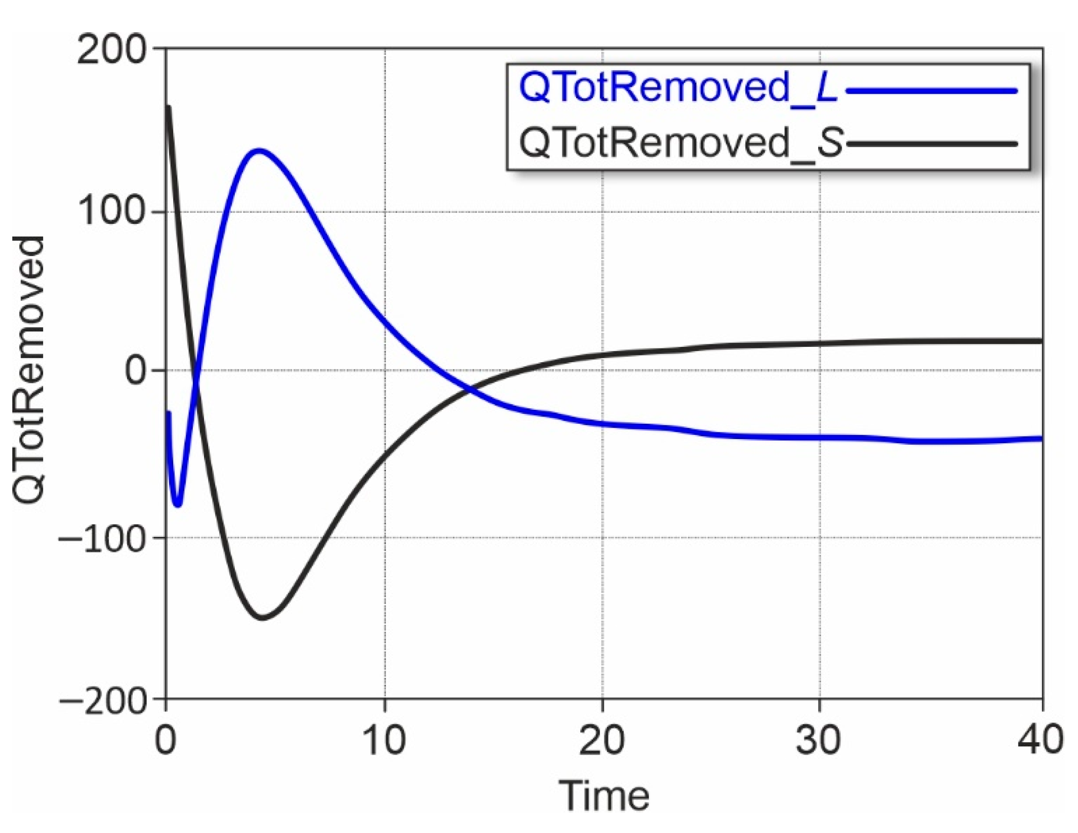
The value of the heat exchange coefficient [W/(m2 × °C)] in the system loop (QTotRemoved_S) and in the feedback line (QTotRemoved_L) at the output of the compressor model depends on a number of parameters, including the chemical composition of the coolant, its structure and density, temperature and other parameters.
In the implemented model in the MSC Easy5 system, these physical characteristics of the coolant in the system circuit and the physical characteristics of the blood in the feedback line, as well as the change in the heat exchange coefficient over time during the process of cooling and warming the coolant in the heat exchanger, were taken into account. The obtained dependences for the coefficient of heat exchange in the system loop (QTotRemoved_S) and in the feedback line at the output of the compressor model (QTotRemoved _L) in time show that in the heat exchanger the temperature from the coolant (aqueous medium) is completely transferred to the feedback line (blood in the circuit), if you do not take into account the heat losses in the walls of the circuit (system of pipes for the coolant). The implemented model in the MSC Easy5 system is confirmed by the temperature data, which is recorded in the cardiopulmonary bypass circuit at the output of the cardiopulmonary bypass apparatus.
- 3.
Data on blood temperature in the CPB circuit obtained in the process of modelling the operation of the temperature control system:
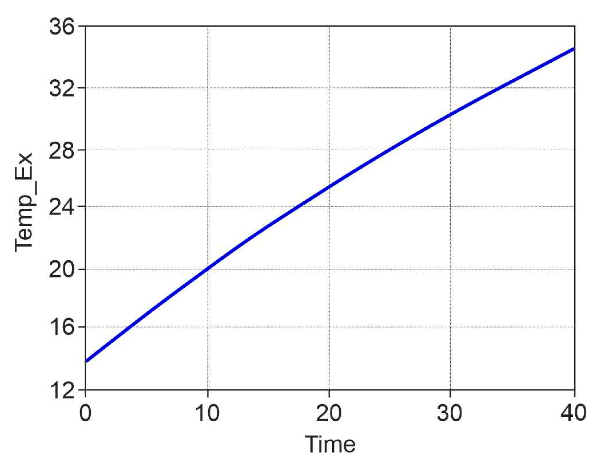
Dependence of blood temperature [T, °C] in the cardiopulmonary bypass circuit at the output of the heart-lung machine (Temp_Ex) has a linear character (
Figure 11), which allows predicting temperature changes in the feedback line and hardware temperature control in the heat exchanger system circuit of the heart-lung machine. In the model implemented in the MSC Easy5 system, the initial data for controlling the temperature in the heat exchanger is the blood temperature in the heart-lung machine, which is measured by sensors in the esophagus or a thermal imaging camera on the myocardial surface during cardiopulmonary bypass.
4. Conclusions
The created model of the temperature control circuit in the heart-lung machine’s heat exchanger using a programmable microcontroller and specialized temperature control algorithm in the C language allows for the investigation of the functionality of existing heat exchangers and developed algorithms for temperature control.
The created model can be used to identify the control system’s flaws, as well as aid in making the necessary decisions before a real prototype of the product is produced and to conduct virtual tests of the developed device at the design stage.
The application of a created mathematical model based on functional blocks will optimize the parameters of the developed temperature control system in the heat exchanger of the heart-lung machine and increase the safety of cardiac surgery under cardiopulmonary bypass conditions.
The development of our model will help surgeons more accurately determine the timing of the bypass based on the input parameters for each patient. Thus, it will improve the safety of the operation and reduce the negative consequences of the use of artificial blood circulation.


 and
and 


