Article

Non-Isothermal Hydrodynamic Characteristics of a Nanofluid in a Fin-Attached Rotating Tube Bundle

by
Mashhour A. Alazwari
1 and
Mohammad Reza Safaei
1,2,3,*
1
Mechanical Engineering Department, Faculty of Engineering, King Abdulaziz University, Jeddah 21589, Saudi Arabia
2
Department of Medical Research, China Medical University Hospital, China Medical University, Taichung 40402, Taiwan
3
Department of Civil and Environmental Engineering, Florida International University, Miami, FL 33174, USA
*
Author to whom correspondence should be addressed.
Mathematics 2021, 9(10), 1153; https://doi.org/10.3390/math9101153
Submission received: 21 April 2021 / Revised: 13 May 2021 / Accepted: 17 May 2021 / Published: 20 May 2021
(This article belongs to the Special Issue Modeling and Numerical Analysis of Energy and Environment 2021)

Abstract

:
In the present study, a novel configuration of a rotating tube bundle was simulated under non-isothermal hydrodynamic conditions using a mixture model. Eight fins were considered in this study, which targeted the hydrodynamics of the system. An aqueous copper nanofluid was used as the heat transfer fluid. Various operating factors, such as rotation speed (up to 500 rad/s), Reynolds number (10–80), and concentration of the nanofluid (0.0–4.0%) were applied, and the performance of the microchannel heat exchanger was assessed. It was found that the heat transfer coefficient of the system could be enhanced by increasing the Reynolds number, the concentration of the nanofluid, and the rotation speed. The maximum enhancement in the heat transfer coefficient (HTC) was 258% after adding a 4% volumetric nanoparticle concentration to the base fluid and increasing Re from 10 to 80 and ω from 0 to 500 rad/s. Furthermore, at Re = 80 and ω = 500 rad/s, the HTC values measured for the nanofluid were 42.3% higher than those calculated for water, showing the nanoparticles’ positive impact on the heat transfer paradigm. Moreover, it was identified that copper nanoparticles’ presence had no significant effect on the system’s pressure drop. This was attributed to the interaction of the fluid flow and circulated flow around the tubes. Finally, the heat transfer coefficient and pressure drop had no considerable changes when augmenting the rotation speed at high Reynolds numbers.

1. Introduction

Heat transfer is a vital transport phenomenon in the industrial sector, which witnesses abundant heat transfer applications, such as cooling microelectronic devices, and high-heat-flux-removal applications, such as heat sinks. Thus, it is imperative to develop new generations of cooling systems that offer high efficiency and high performance at low cost [1]. An efficient heat-exchanging medium transports a large amount of thermal energy in a confined space with a minimum external energy requirement. Much effort has been made in developing passive systems to reduce the operating cost of heat transfer in systems. In some research, the systems’ geometrical specifications and hydraulic characteristics were amended such that the heat transfer was intensified due to the change in the fluid regime [2]. Simultaneously, there are studies in which better thermal performance was achieved by changing the working fluid [3,4].
Nanofluids are by far one of the potential options for improving heat transfer. This is predominantly attributed to solid particles’ effect on the liquid’s physical properties, such as thermal conductivity and the presence of some micro-scale phenomena, such as Brownian motion [5,6]. It has already been demonstrated that a nanofluid with a smaller diameter can provide better thermal conductivity, more stability, and a lower pressure drop in comparison with larger particles, such as micron-sized particles or clusters [7]. Generally, solid nanoparticles are less than 100 nm and are uniformly dispersed in conventional liquids, such as water or oil. The solid particles’ uniform dispersion can create high thermal conductivity, particularly when close to the system’s hot walls and boundary [8]. Nanoparticles can also induce Brownian motion to further boost the heat transfer mechanism due to the nanoparticles’ random movement in the bulk of the liquid [9]. As such, the focus has been redirected to the potential application of nanofluids in thermal systems. For example, Abdollahi-Moghaddam et al. [10] examined the heat transferability of a CuO/water nanofluid. They observed that the heat transfer of nanofluid was 2.8 times bigger than that of water. Simulations showed that by using the nanofluid, water consumption could be decreased by 37.6% or the system size will shrink by 55%.
Shape modification of the heat exchanging media is another potential solution that can increase heat transfer. For example, it was desirable for the hydrodynamics of shell and tube heat exchangers to change their baffles arrangement to elliptical or angular layout or jagged edges [11,12,13]. This, in turn, can improve the heat transfer, mainly when nanofluids are implemented as the heat transfer fluid in the system [14,15]. For example, Said et al. [16] experimentally and numerically investigated CuO nanoparticles’ potential impact on a shell and tube heat exchanger’s thermal performance. They noticed that using a nanofluid with 0.3% CuO nanoparticles (volumetric concentration) can improve the heat transfer coefficient by 7%, whereas using Al2O3 and TiO2 can promote the HTC by 41% and 37%, respectively. Sarafraz and co-workers have assessed various ranges of pure liquids [17] and nanofluids in single- and two-phase flow conditions [18]. They reported that, unlike pure liquids, for the same thermodynamic systems, nanofluids can promote the HTC in single-phase operating mode, while in two-phase systems, due to the deposition of the nanoparticles, the performance might decrease, remain unchanged, or increase [19,20]. Recently, a horizontal heat exchanger was evaluated by Kashminder Singh et al. [21] when the laminar flow of water containing Si-PDA/Ag nanoparticles was utilized. The observance indicated that, in this flow regime, the heat transfer can rise to 50%. The turbulent regime was experimentally studied by Zheng et al. [22] by considering Al2O3/water as a working fluid. The foundation showed that the Nusselt number could be improved by up to 23.2%. Since there have been extensive studies conducted on the nanofluids’ thermal performance, in Table 1, a summary of these studies is represented for benchmarking and comparison only.
The heat transfer mechanism in tube bundles is of particular interest, as such systems can create an exciting heat transfer mechanism. Generally, a simple tube bundle has no significant effect on the thermal performance of the heat exchangers. However, more advanced bundles can change the fluid regime and hence significantly affect the HTC value. Recently, rotating tubes have attracted attention due to the remarkable combined effect of heat and fluid flow [33,34,35]. For example, Khan et al. [36] numerically studied a tube bundle’s hydrodynamic performance with staggered states. They described Nu as a function of the length and longitudinal of the twisted pitch and its transverse. A few studies investigated the role of more than one rotating tube in channels or even in cavities. Khanafer et al. [37] simulated the effect of two rotating cylinders in a cavity on heat transfer. The foundation indicated that Nu and the flow pattern are affected by the cylinder rotation, but the rotation speed had no significant effect on the Nusselt number. Selimefendigila and Oztop [38] modeled the heat transfer and fluid flow of a CNT-based nanofluid onto a tube bundle. They found that having rotating tubes results in the promotion of heat transfer. Accordingly, they reported a 244% enhancement in the Nusselt number. In another study [33], the same authors investigated this rotational tube bundle inside a cavity. They obtained 40% and 37.7% heat transfer enhancements for CNT/water and Ag-MgO/water nanofluids, respectively. The results also indicated that the place and size of the tube bundle could affect the heat transfer performance; furthermore, the CNT-based nanofluid was favorable because of the higher Nu and lower pressure drop. Marzban et al. [39] examined the performance of a rhombic tube bundle in the presence of an NDG/water nanofluid. The rotated square tube arrangement indicated the highest heat transfer performance and friction factor. Daneshvar Garmroodi et al. [40] carried out a numerical study to evaluate Cu/water nanofluid’s effect through a cavity with two rotating smooth cylinders. They concluded that applying rotational force and using nanofluid significantly enhance the heat transfer. Their investigation of rotating tubes’ location indicated that the tubes’ vertical layout has the most considerable influence on heat transfer. Furthermore, increasing the Hartman number led to a reduction in heat transfer. It was more noticeable in the vertical arrangement.
As previously discussed, a rotating tube brings a combined effect by changing the system’s heat and fluid flow characteristics. However, to the best of the author’s knowledge, very few studies focus on the flow and mechanism of the heat transfer in contrast to applied research with bundle tubes, which have been extensively studied and presented in the literature. Rotating tubes and nanofluid can significantly affect the hydrodynamics of the tube bundle. It enhances the flow circulation through the heat exchanging process while augmenting the heat transfer surface at a molecular scale. However, a nanofluid boosts the energy loss and pressure drop because of the higher dynamic viscosity induced by dispersing nanoparticles in the working fluid [41].
In light of the above discussion, in this study, rotating tubes containing fins were studied to further understand the mechanism and the system’s performance under the influence of rotating tube bundles. An aqueous copper nanofluid was used to combine and intensify the heat transfer enhancement due to increased thermal conductivity and Brownian motion. For this purpose, a nanofluid-containing microchannel was considered in which fin-attached tubes were assumed to rotate at defined rotating velocities. Such an innovative system can be used for designing highly efficient thermal engineering systems. Moreover, developing the present configuration can be helpful for a better understanding of thermal and shear boundary layers for the rotating tubes and the geometry of the microchannel.

2. Mathematical Modeling
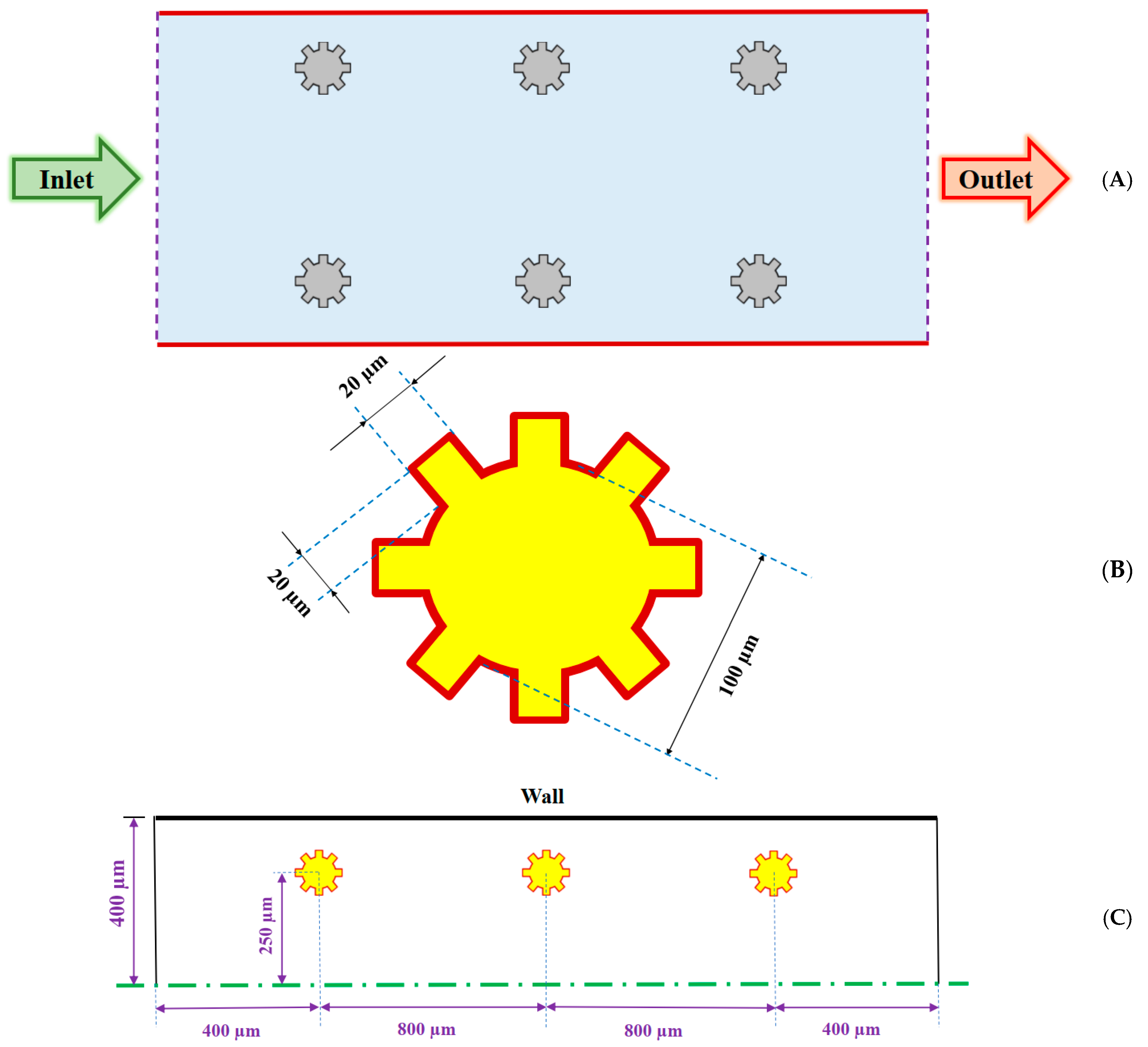
2.1. Physical Model

A microchannel with six rotating tubes (three in each row) was modeled in this study. The microchannel was fabricated from aluminum with a 2400 µm length and a 400 µm width. As shown in Figure 1a, the tube bundle was organized into six tubes, where their centers were placed at 250 µm from the microchannel center. On each tube, eight fins with a thickness of 20 µm were mounted. The geometrical specification of the fins is shown in Figure 1b. To reduce the consumption of computational resources, only half of the geometry was modeled, as shown in Figure 1c. Furthermore, in Table 2, the geometrical specifications of the system are given.

2.2. Governing Equations

The governing equations are as follows [42]:
Continuity equation:
t ( ρ m ) + · ( ρ m V m ) = 0
where
V m = k = 1 n φ k ρ k V k ρ m = V k
and
ρ m = K = 1 n φ k ρ k
Momentum equation:
t ( ρ m V m ) + · ( ρ m V m V m ) = P + · [ μ m ( V m + V m T ) ]
where
μ m = k = 1 n φ k μ k
Energy equation:
t ρ m h m + · ( ρ m h m V m ) + · ( P V m ) = · ( k e f f T )
where
ρ m h m = Z = 1 n ( φ Z ρ Z h Z )
Volume fraction equation for the second phase:
t ( φ p ρ p ) + · ( φ p ρ p V m ) = · ( φ p ρ p V d r , p )
where
V d r , p = V p f k = 1 n Φ k ρ k ρ m V f k
and
V p f = V p V f = 0

2.3. Boundary Conditions of the Problem

As a heat transfer fluid, a copper/water nanofluid was chosen to flow inside the microchannel. This was to induce Brownian motion and to improve the physical properties, such as the thermal conductivity. The fluid flow was tuned such that Reynolds numbers of 10, 20, 40, and 80 were applied to the microchannel. The flow was considered to be under steady-state, laminar, incompressible, and fully developed conditions. In this study, fixed adiabatic fins were investigated, along with fin clockwise rotating velocities equal to 100, 250, and 500 rad/s. The effects of thermal radiation, viscous dissipation, joule heating, and displacement currents were neglected. The walls of the microchannel were subjected to a constant heat flux equal to 10,000 W/m2. Moreover, at the microchannel outlet, a pressure outlet was adjusted, while the gravitational force was assumed to be negligible. Furthermore, the microchannel’s wall was insulated, while the inlet temperature was set at 293 K.

2.4. Thermophysical Properties of the Cu/Water Nanofluid

A copper/water nanofluid was used as the working fluid. The density and dynamic viscosity of the nanofluid was defined using Brinkman’s models [43]:
ρ n f = φ ρ n p + ( 1 φ ) ρ b f
μ e f f = μ b f / ( 1 φ ) 2.5
while the heat capacity property was obtained using Xuan and Li’s [44] model:
( ρ C p ) n f = ( 1 φ ) ( ρ C p ) b f + φ ( ρ C p ) n p
Since Chon et al.’s [45] thermal conductivity model was obtained based on Brownian motion at different temperatures by including the sub-layer thickness [46], it was used in this study as follows:
k n f k f = 1 + 64.7 ϕ 0.746 ( d f d p ) 0.369 ( k p k f ) 0.7476 P r 0.9955 R e 1.2321
where
P r = μ f ρ f α f
as the Prandtl number and
R e = ρ f k b T 3 π μ 2 l f
which is the Brownian Reynolds number. lf is expressed as the base fluid’s mean free path, which is equal to 0.17 nm for water, and the temperature-dependent viscosity of the base fluid, µ, is defined as:
μ = O × 10 P T Q
where T is the temperature and O, P, and Q are constants. Their values for water are 2.414 × 10⁻⁵, 247.8, and 140, respectively [47]. In Table 3, thermophysical properties of the materials, including the nanofluid at volume concentrations of 2 and 4%, are presented based on the recommendation of [48].

2.5. Numerical Procedure

The finite volume method (FVM) [49,50] was used to solve the governing equation using the ANSYS FLUENT software package [51,52]. The equations were obtained for two-dimensional nanofluid flow by using a mixture model. Continuum theories for the mixture model were expanded by Truesdell and Toupin [53], Eringen and Igram [54], and Drumheller and Bedford [55]. Ahmadi et al. [56,57,58,59,60] developed the model more, especially for turbulent flows. The pioneer of applying the mixture theory for nanofluid modeling is Behzadmehr et al. [61] in 2007. The primary assumption of this method is that the base fluid and nanoparticles flow together while the base fluid carries the nanoparticles [47].
The second-order upwind method [62,63] was employed to discretize the governing equations, while the SIMPLEC algorithm [64,65] was chosen to couple the pressure and velocity. The residual criteria for all governing equations were set to below 10−7.

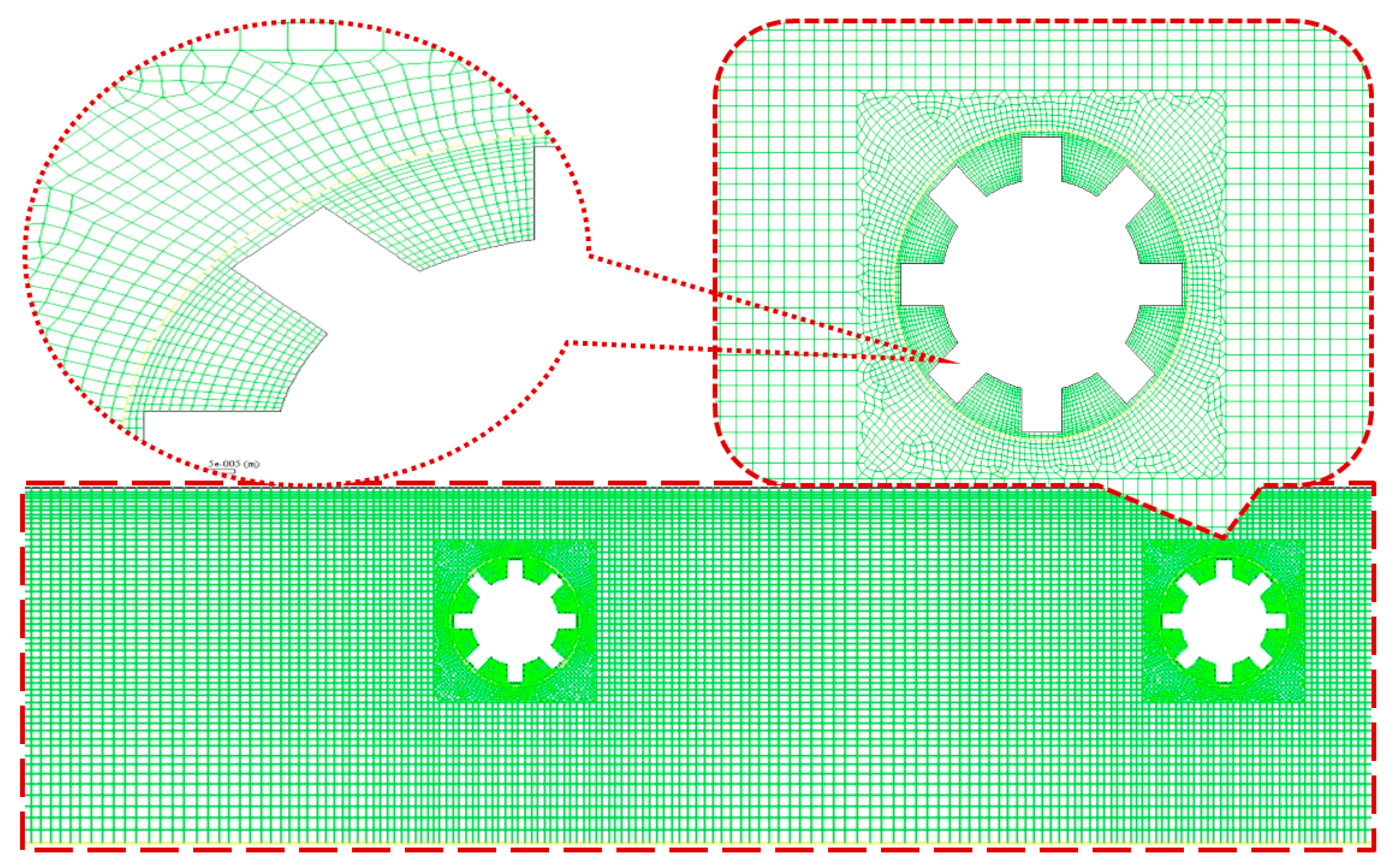
2.6. Grid Independence Analysis

The model results were checked by comparing the average Nusselt number, pressure drop, and maximum temperature through the whole system and for all three fins at four different mesh structures. The results are depicted in Table 4. As shown, when the cell number increased, the parameters’ values became more accurate, approaching a constant value to become independent from the mesh cells. However, the values had no significant differences from each other. Therefore, a cell number of 62161 was chosen for the modeling, which offered sufficient accuracy with reasonable computational resources to solve the governing equations.
A schematic illustration of the mesh structure is given in Figure 2. The density of the grids was higher where the working fluid had a more critical role in it, such as at the walls, the area around the tubes, and the area around the fins, which had the densest grids. Structured meshes were used in this study. Problem zones are frame motion; thus, the moving reference frame was used to solve the problem. The outer zone was fixed, but the moving reference settings were used in the other two zones (near the fins).
As a part of future work, the grid independence study can be checked using the grid convergence index (GCI) recommended by the Fluids Engineering Division of the American Society of Mechanical Engineers as a solid, reliable approach for grid dependence analysis. This approach is described in Roache [66] and employed in several studies, e.g., Sosnowski [67].

2.7. Validation of Numerical Procedure

This section provides information on validating the present numerical solution. A comparison was made between the results obtained from simulation and those available in the literature. As shown in Table 5 and Figure 2, it was revealed that the simulation results were in acceptable agreement with those of previous studies. Thus, the numerical method was concluded to be highly significantly accurate and reliable, which makes it an ideal option for studying nanofluid flow and heat transfer in a closed conduit with rotating-type tube bundles.

2.7.1. Heat Transfer and Fluid Flow over Rotating-Type Tube Bundles

To validate the flow running over rotating-type tube bundles, a comparison was made between the results of this work and those reported by Ghazanfarian and Nobari [68]. They examined convective heat transfer exhibited by a rotating cylinder when there were cross-flow oscillations. The simulation was performed by modeling cross-flow oscillations at different amplitudes and frequencies while assuming three values of 50, 100, and 200 for the Reynolds number and three values of 0.7, 6, and 20 for the Prandtl number. To compare the present simulation with the study mentioned above, the results were obtained for water with the Reynolds number and non-dimensional amplitude equal to 100 and 0.2, respectively. According to Table 5, the results yielded by the present study were in fair agreement with those obtained by Ghazanfarian and Nobari [68], while the minimum and maximum deviations were respectively equal to 3.8% and 9%.
Table 5. Mean Nusselt number for cross-flow oscillations at Pr = 6 and A = 0.2 for Re = 100.
αGhazanfarian and Nobari [68]Present Study%
0.541.342.593.1
135.236.182.8
1.525.826.683.4

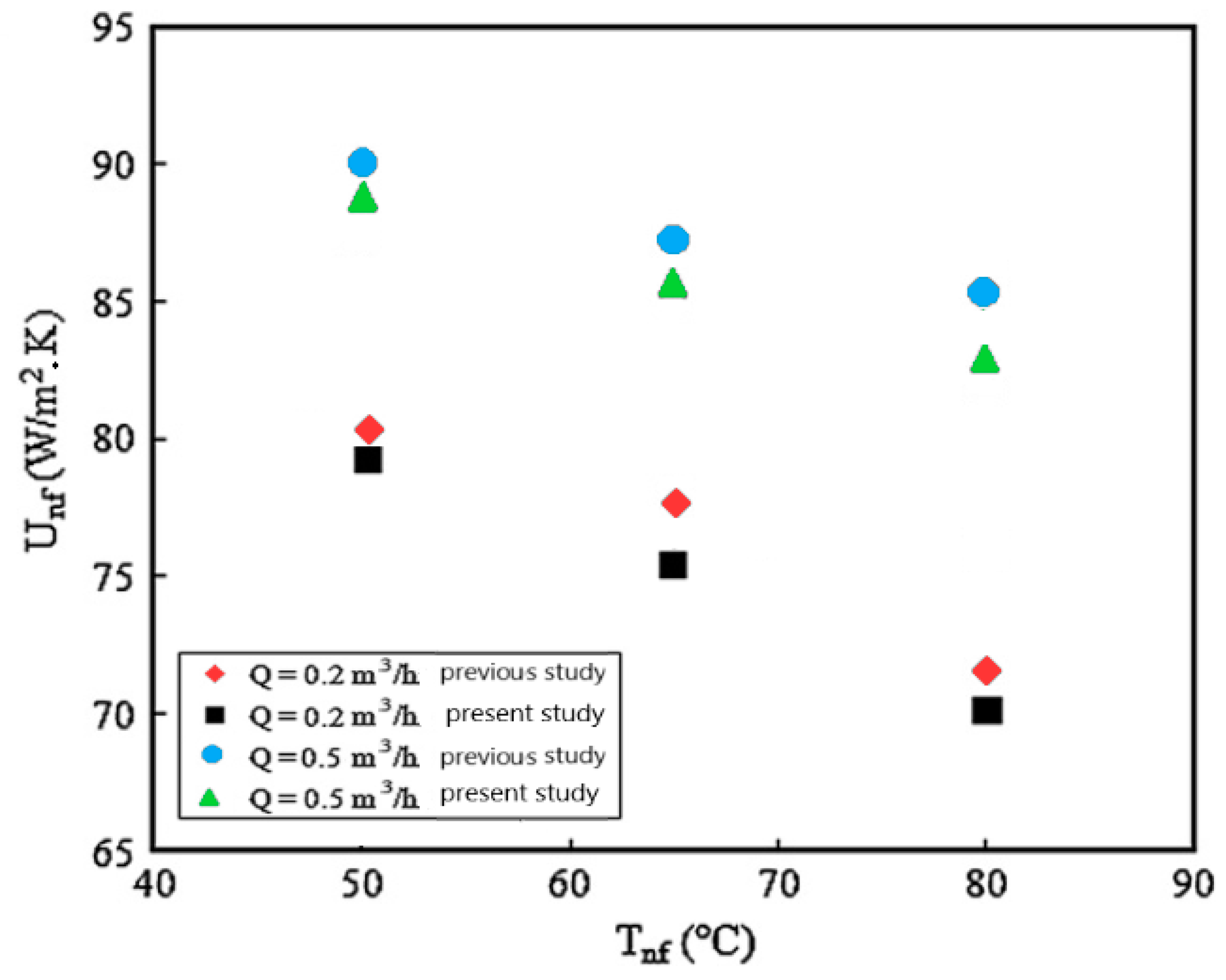
2.7.2. Nanofluid Flow and Heat Transfer in an Air-Finned Heat Exchanger (Comparison with Experimental Data)

The present numerical procedure that can be employed to study nanofluid flow passing through a heat exchanger was then validated with the results reported by Vermahmoudi et al. [69]. As an experimental study, it was performed to investigate the laminar forced convection heat transfer exhibited by water/iron (III) oxide inside an air-finned heat exchanger. Experiments were conducted while the volume concentrations of 0.15%, 0.4%, and 0.65% were considered for the stabilized nanofluid of Fe2O3/water. The flow rate was varied between 0.2 and 0.5 m3/h; the air-finned heat exchanger was composed of 34 vertical tubes. A cross-flow was formed inside the tube bank with a flow rate between 740 and 1009 m3/h at temperatures of 50, 65, and 80 °C; furthermore, hot working fluid entered the heat exchanger. The validation was performed by comparing the overall heat transfer coefficient associated with the nanofluid obtained by Vermahmoudi et al. [69]. Figure 3 indicated a perfect agreement between the results corresponding to the present numerical procedure and the study in question.

3. Results and Discussion

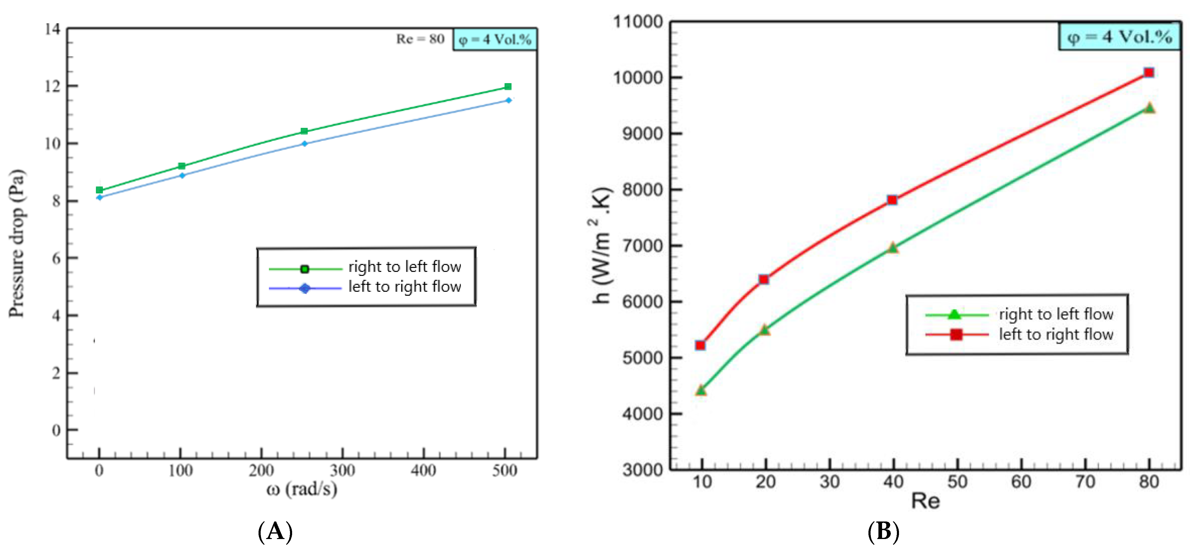
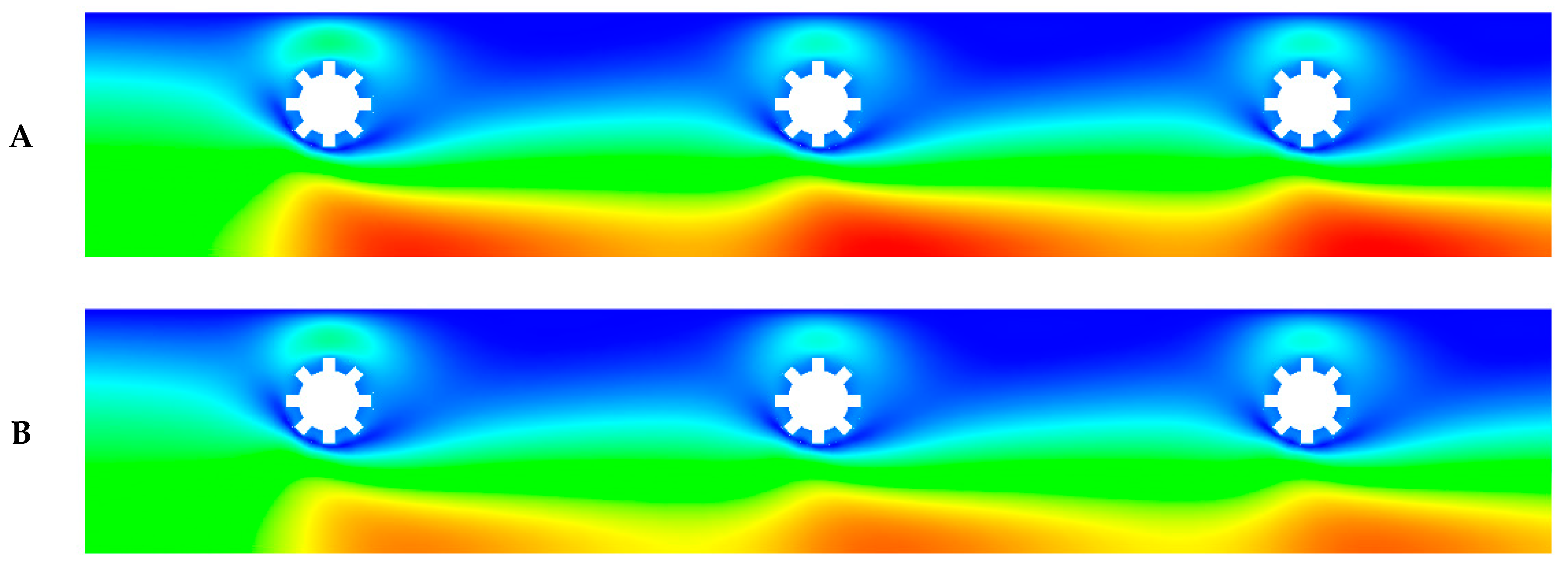
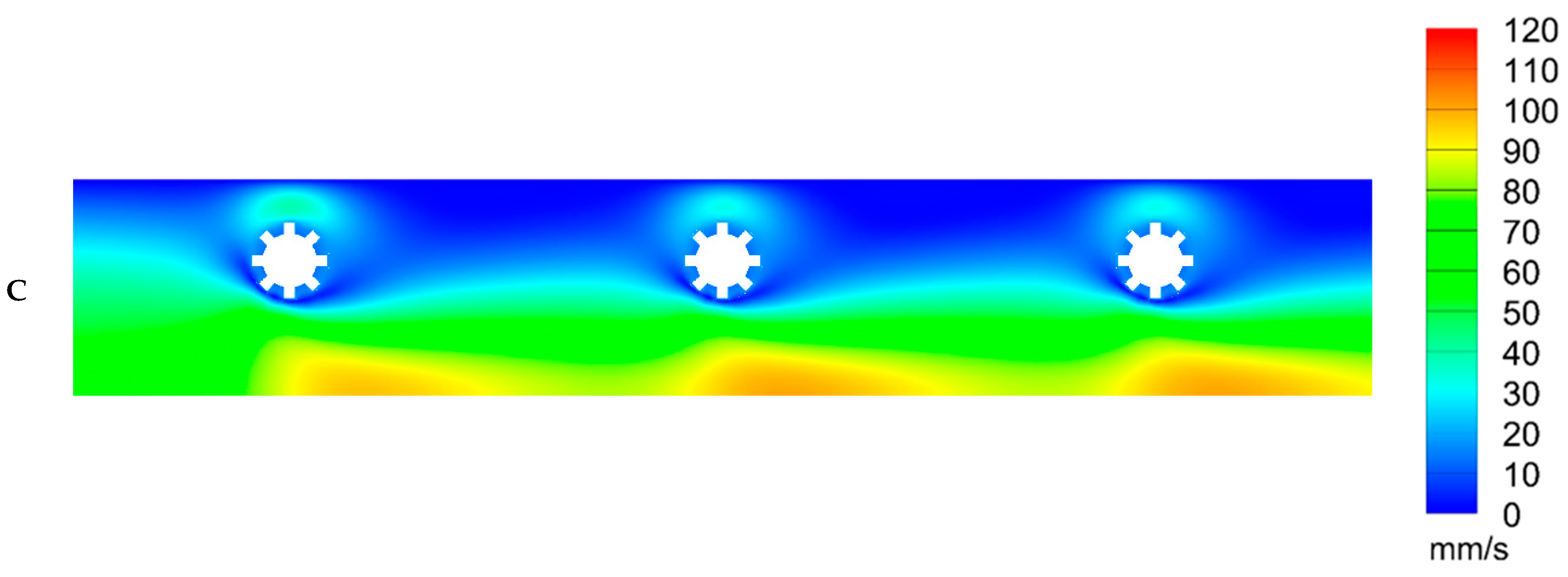
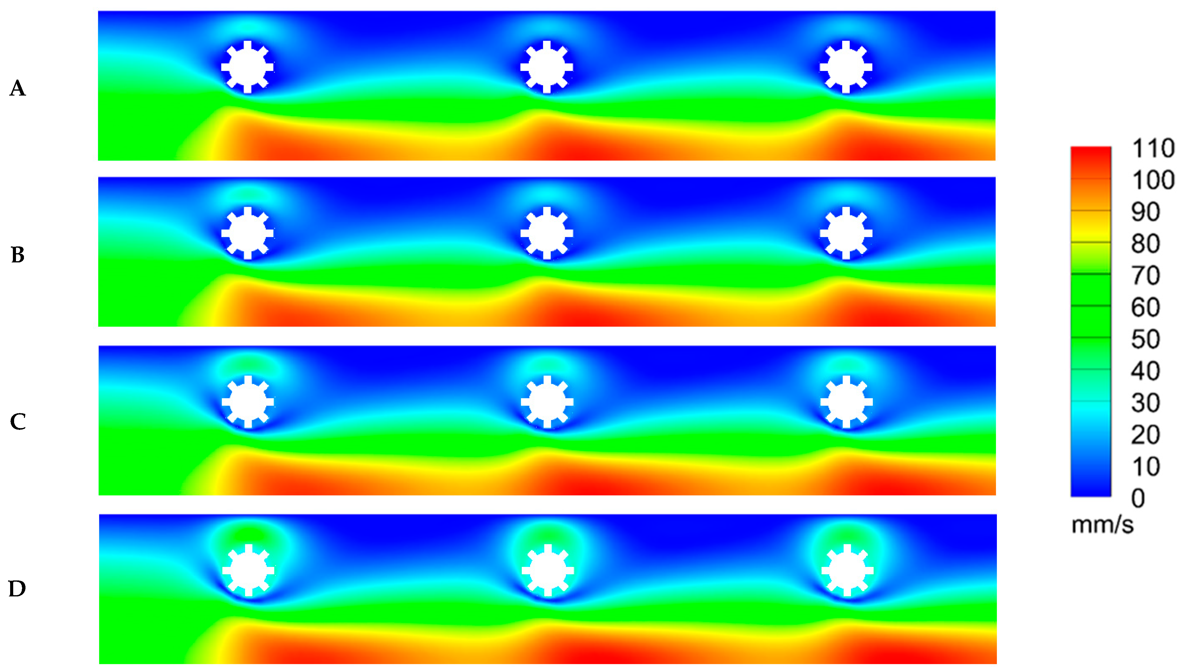
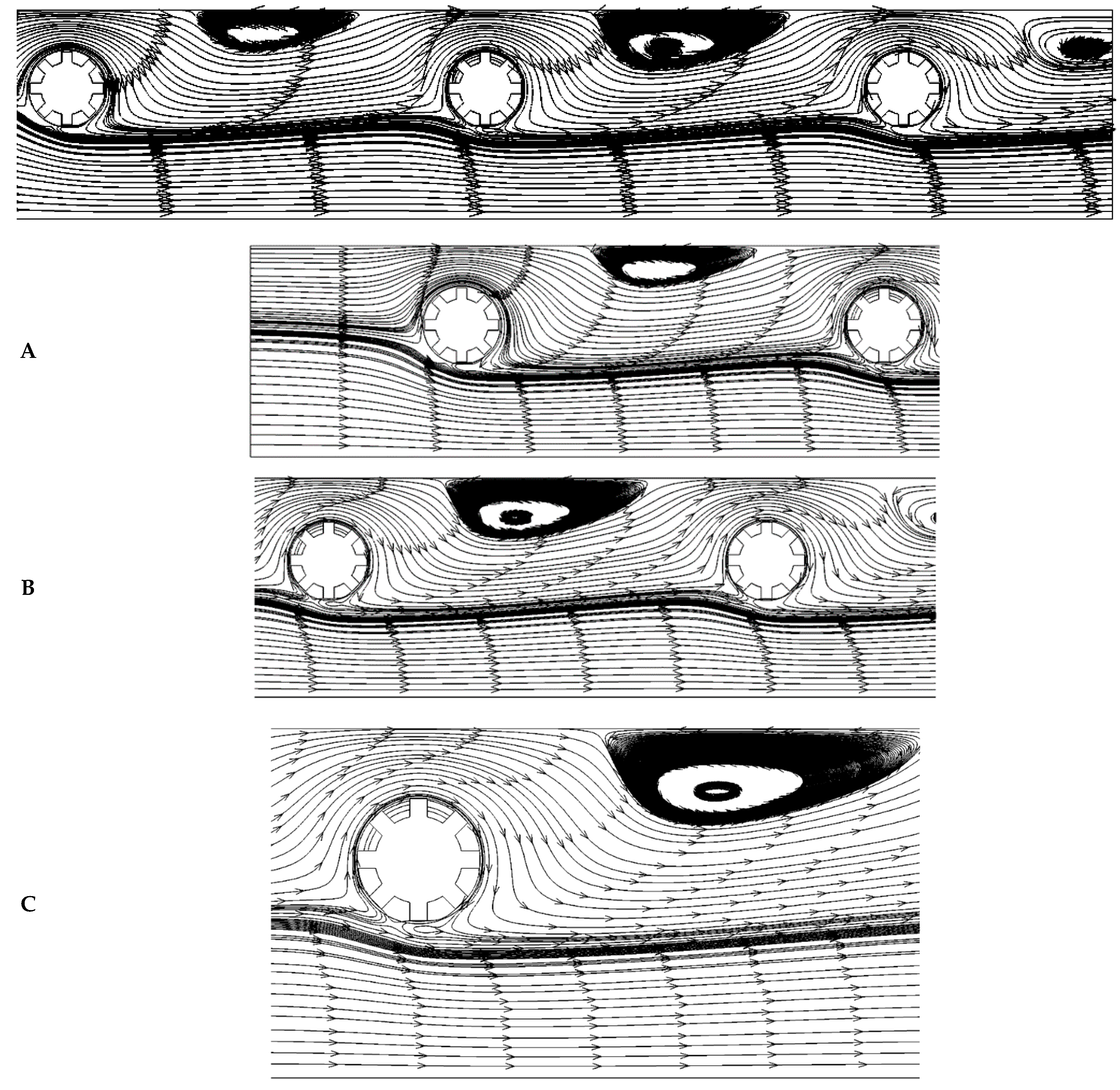
3.1. Flow and Rotation Direction Effects

Figure 4A,B indicates the heat transfer coefficient and pressure drop for left-to-right and right-to-left flow direction with clockwise rotational tube bundles. According to the graphs, it is evident that the left-to-right flow provided a higher heat transfer and lower pressure drop, which means that the left-to-right flow had higher performance.
The reverse rotation of the tube bundle (counter-clockwise) was also considered in this study. When the tube bundle rotated in the counter-clockwise direction, the right-to-left flow direction was more efficient than the left-to-right flow. It was surprising to find that the results corresponding to the right-to-left flow with counter-clockwise rotational tube bundles were precisely the same as those obtained for the left-to-right flow with clockwise rotational tube bundles. Therefore, the results of the second case did were not reported in this investigation.

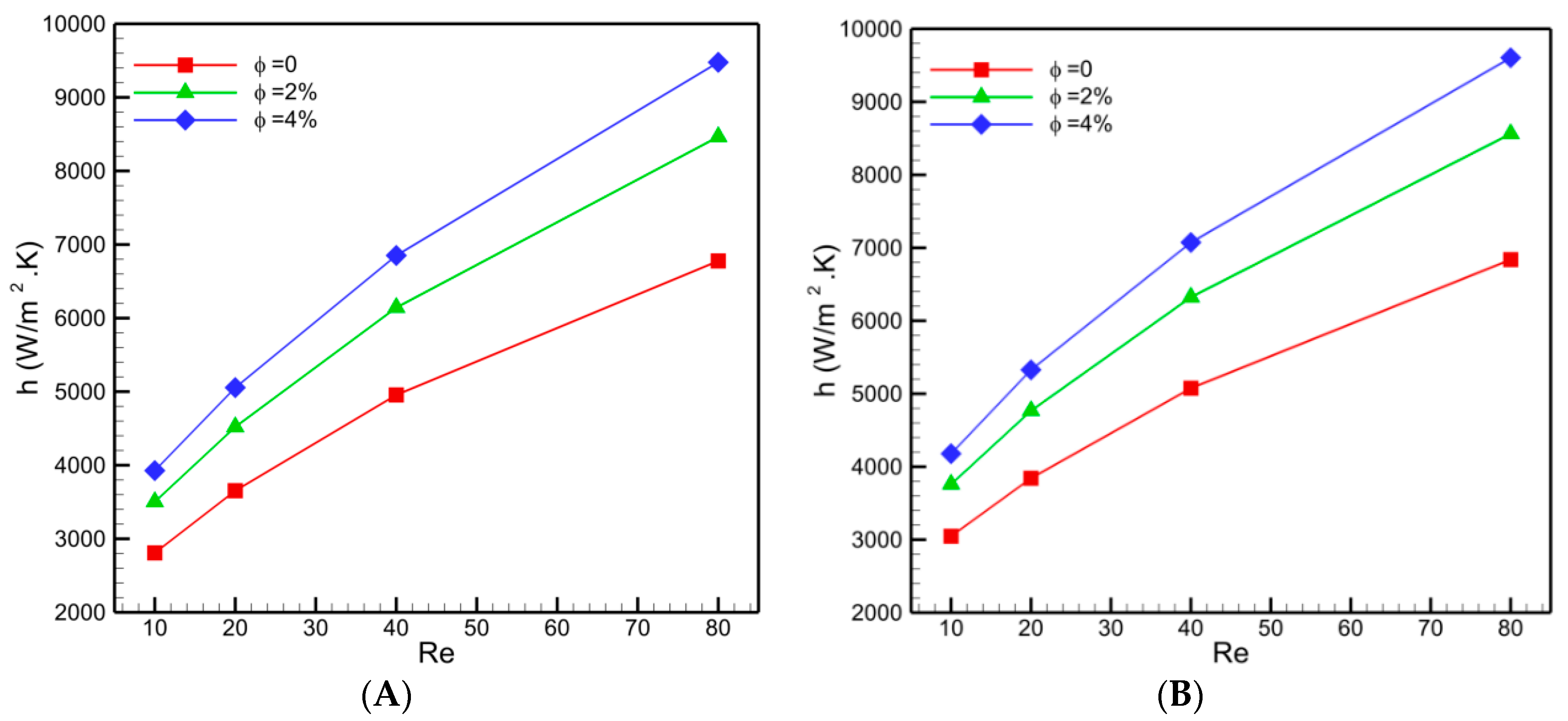
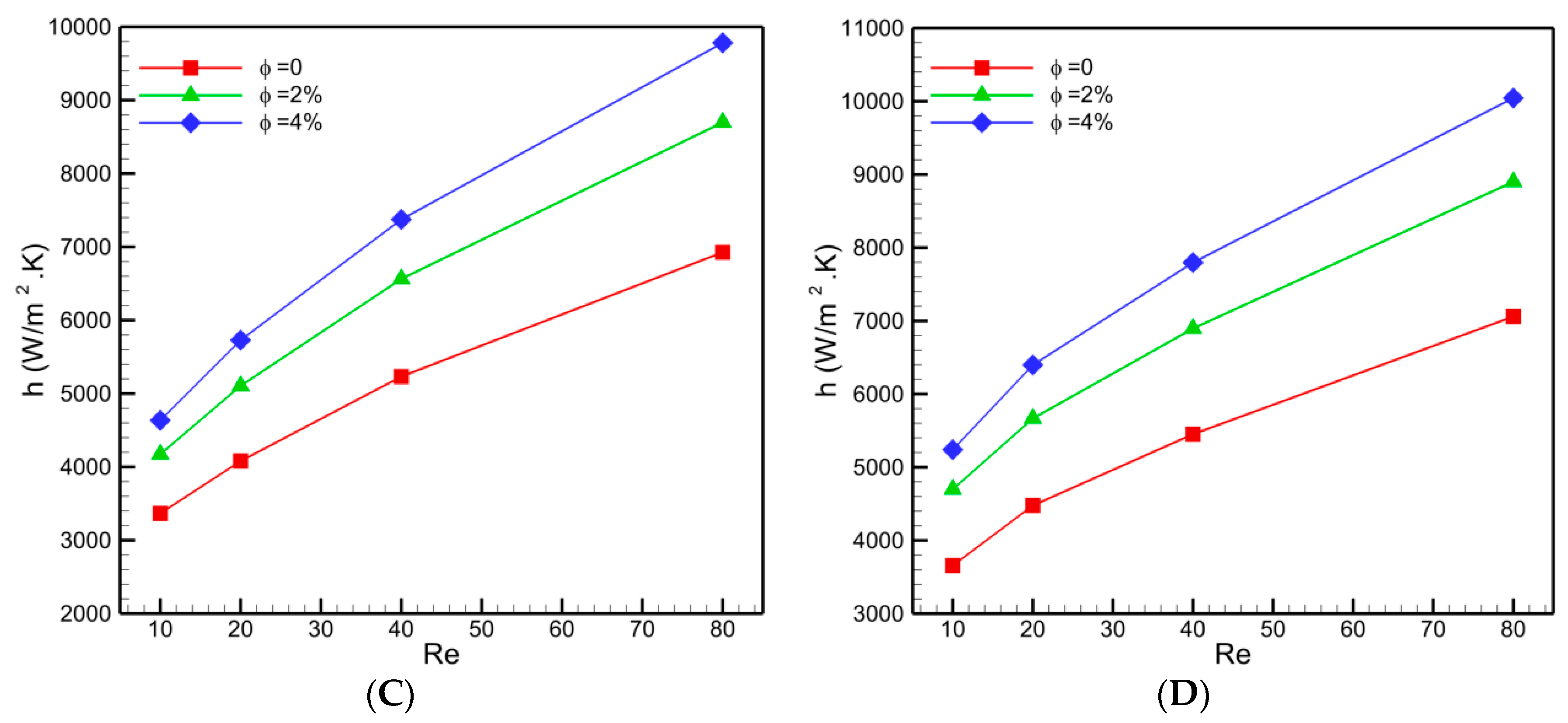
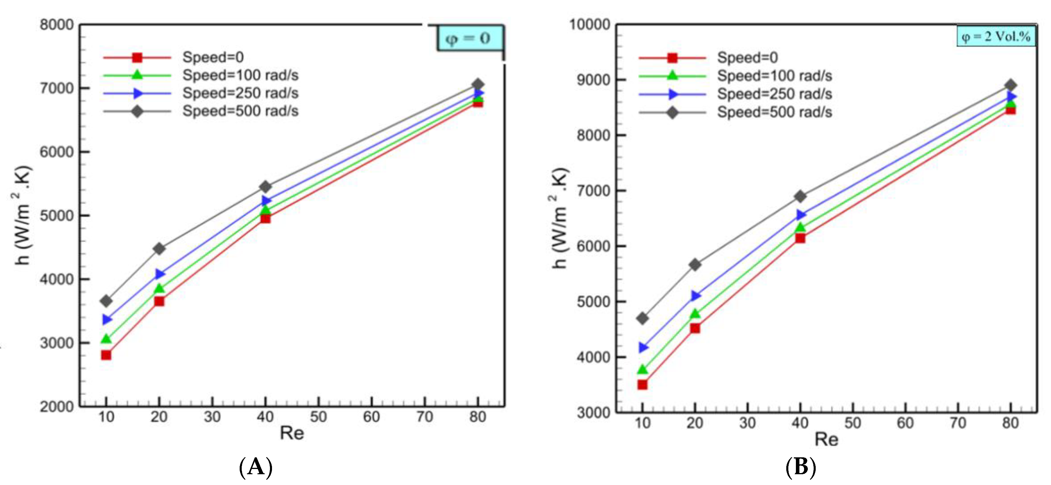
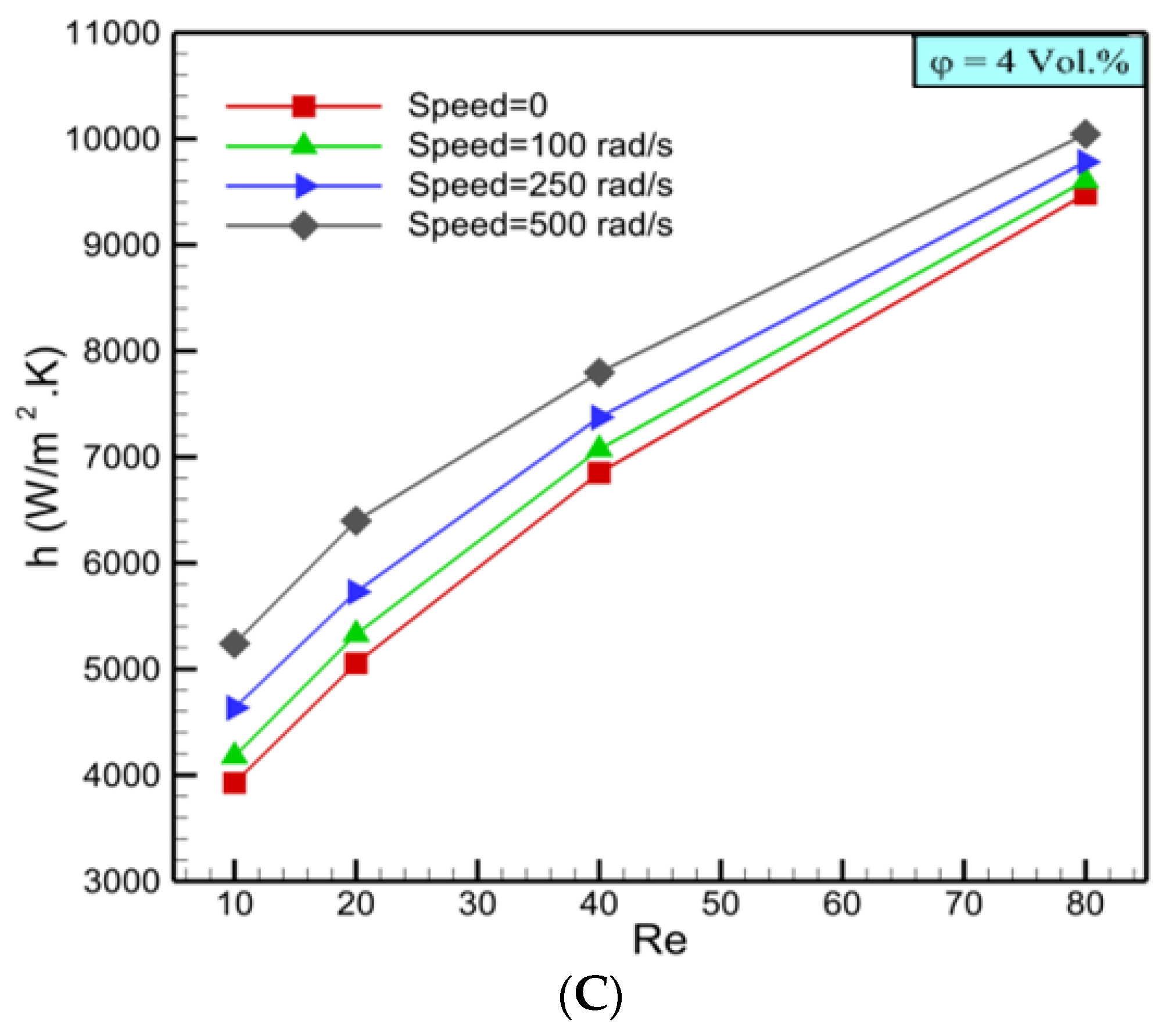
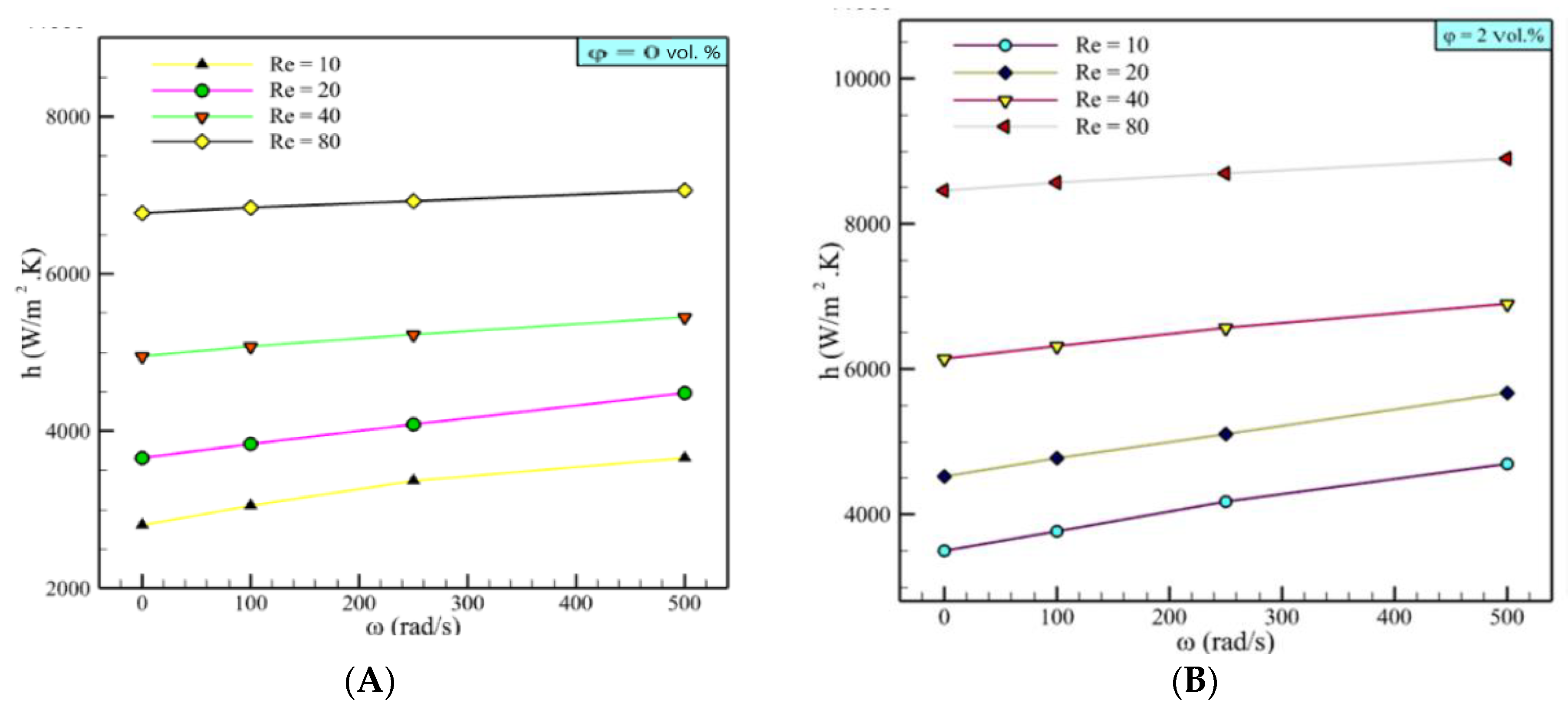
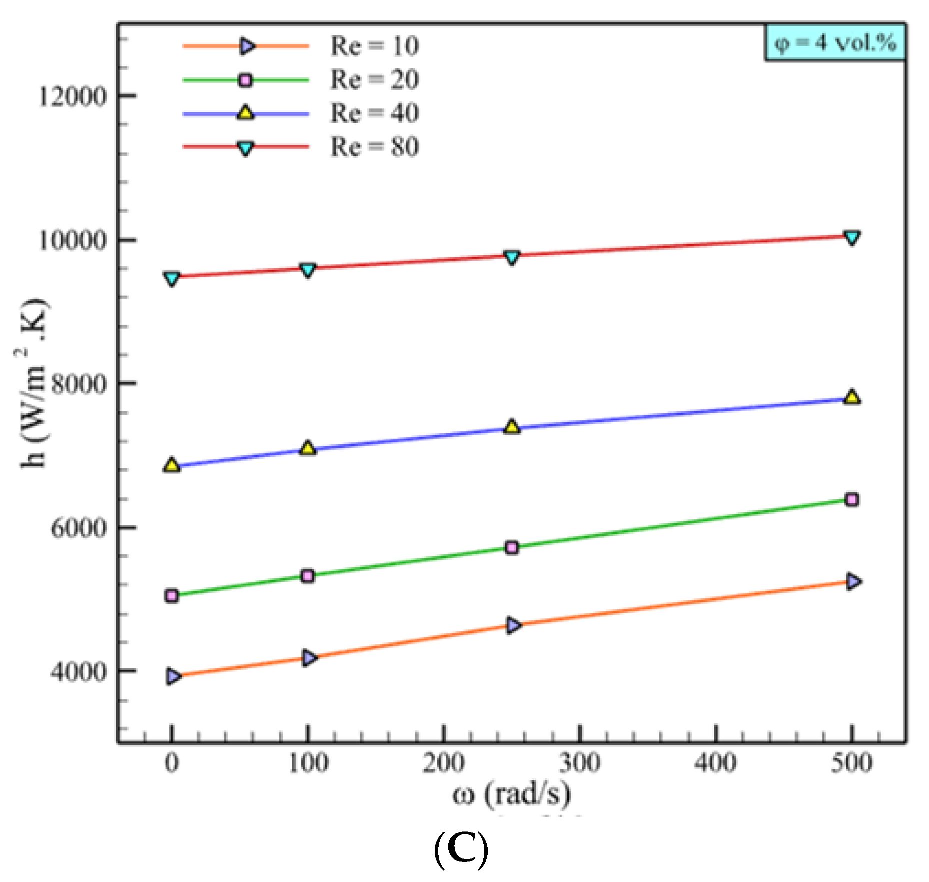
3.2. Heat Transfer Coefficient

In Figure 5, the system’s calculated heat transfer coefficient of the nanofluid at various concentrations and different Reynolds numbers and rotation speeds are given in the presence of a rotating tube bundle containing six tubes, with each one attached by fins. The results are illustrated by taking into account four Reynolds numbers (Re’s) of 10, 20, 40, and 80, as well as three rotation speeds such as 100, 250, and 500 rad/s. The nanofluid concentrations were considered to be 0%, 2%, and 4% volume fractions. It was observed that the hydrothermal efficiency of the system changed when increasing the rotation speed of tubes.
As shown, increasing Re led to heat transfer enhancement for the nanofluid and water with and without rotating tubes. It was also identified that the effect of Re on heat transfer enhancement was almost the same for water and nanofluids. This was because the increasing slopes of the heat transfer enhancement were approximately the same for both the nanofluid and water. The nanofluid at 4% concentration had a 37 to 43.3% higher heat transfer coefficient than the water at all corresponding Re and ω values. This was because of the copper nanoparticles’ existence in the base fluid that created enhanced thermal conductivity and Brownian motion.
Figure 6 illustrates the effect of the nanoparticles on the velocity through the tube bundle. A comparison between the figures shows that adding nanoparticles to the base fluid caused a velocity reduction. It was evident that for the case with a water working fluid, the maximum velocity, at the middle line, was about 120 mm/s, while the maximum velocity for the 2 vol.% and 4 vol.% nanofluids were approximately 110 mm/s and 100 mm/s, respectively. Moreover, by increasing the amount of nanoparticles in the working fluid, the vortex’s velocity magnitude above the tubes was reduced. As mentioned, adding nanoparticles to a base fluid led to density and dynamic viscosity augmentation based on Equations (11) and (12). The presence of nanoparticles in the base fluid increased the shear stress between the layers of the fluid. As a result, based on the shear stress of Newtonian fluids ( τ = μ U y ), the dynamic viscosity of the nanofluid was enhanced. On the other hand, at a constant Re, increasing the volume fraction of the nanoparticles in the base fluid caused the ratio of ρ μ nanofluid to increase; thus, the velocity magnitude decreased.
Figure 7 shows the heat transfer coefficient against the Reynolds number for various rotation speeds and different nanoparticle volume fractions. As expected, the heat transfer coefficient increased with Re; however, the upward slope is remarkable. Moreover, just as the heat transfer coefficient increased with Re for stationary tubes, the trend was seen for rotating tubes. However, at higher Re, the effect of the rotation was decreased. Furthermore, at a lower Reynolds number, the rotating tubes considerably affected the heat transfer coefficient, but the effect gradually dwindled as Re increased. The difference between heat transfers corresponding to the stationary tubes and the tubes rotated with 500 rad/s was 30% for water at Re = 10. These differences for nanofluids with 2 vol.% and 4 vol.% concentrations were 34.2% and 33.4%, respectively. However, for Re = 80, these differences were 4%, 5.1%, and 5.9% for water and 2 vol.% and 4 vol.% nanofluids.
In Figure 8, the heat transfer coefficient (HTC) is plotted versus the rotation speed for various Re values and nanofluid concentrations to better understand the influence of the rotating tubes on the tube bundle hydrodynamics. As shown, the HTC increased with an increase in the rotation speed. Moreover, by increasing the Re number, the HTC value was increased. This was because the spatial velocity profile changed; therefore, plotting a velocity contour at φ = 2 vol.% and Re = 40 could help to understand the fluid behavior better (Figure 9). At a higher rotation speed, the velocity of working fluid in the vicinity of the microchannel’s wall was augmented such that for ω = 0 rad/s, the velocity in this section was approximately 30 mm/s, whereas it was 70 mm/s for ω = 500 rad/s. To achieve a better heat transfer performance, the fluid flow should circulate near the heat source to absorb more thermal energy and transfer it to the fluid’s bulk. By applying a rotating force to the tubes, fluid circulation near the heat source was adequately achieved, promoting heat transfer near the hot walls.
As shown in Figure 10, the streamlines for the nanofluid for φ = 2 vol.%, Re = 40, and ω = 500 rad/s are illustrated. The counter-clockwise rotation of the tubes, as well as the existence of fins, led to the fluid flow being separated into two different shear layers. This separation changed the flow pattern through the tube bundle. The layer located below the tubes (the fluid flow with the lowest disturbance) left the microchannel and another layer above the tubes over the section with a highly dense streamline. The former layer was created with the rotating tubes such that the fluid flow accelerated below the tubes, and the fluid around the tubes was pushed into the trajectory line of the bulk flow, which passed from the middle of the microchannel near the symmetry line.
The latter layer was created when the fluid flow collided with the first tube, where the fluid circulation induced by the attached fins caused a counter-current flow against the primary fluid flow and created a high-pressure region. Then, the counter-current flow redirected the main flow to the area between the tube and wall. In this layer, the fluid flow was compact, and hence, dense streamlines formed. After crossing this area, the fluid flow entered a higher cross-sectional area in which a low pressure was generated by entering a wider space, while a high-pressure area occurred due to the second rotating tube and its fins. Hence, a vacant zone appeared between the two tubes and near the wall.

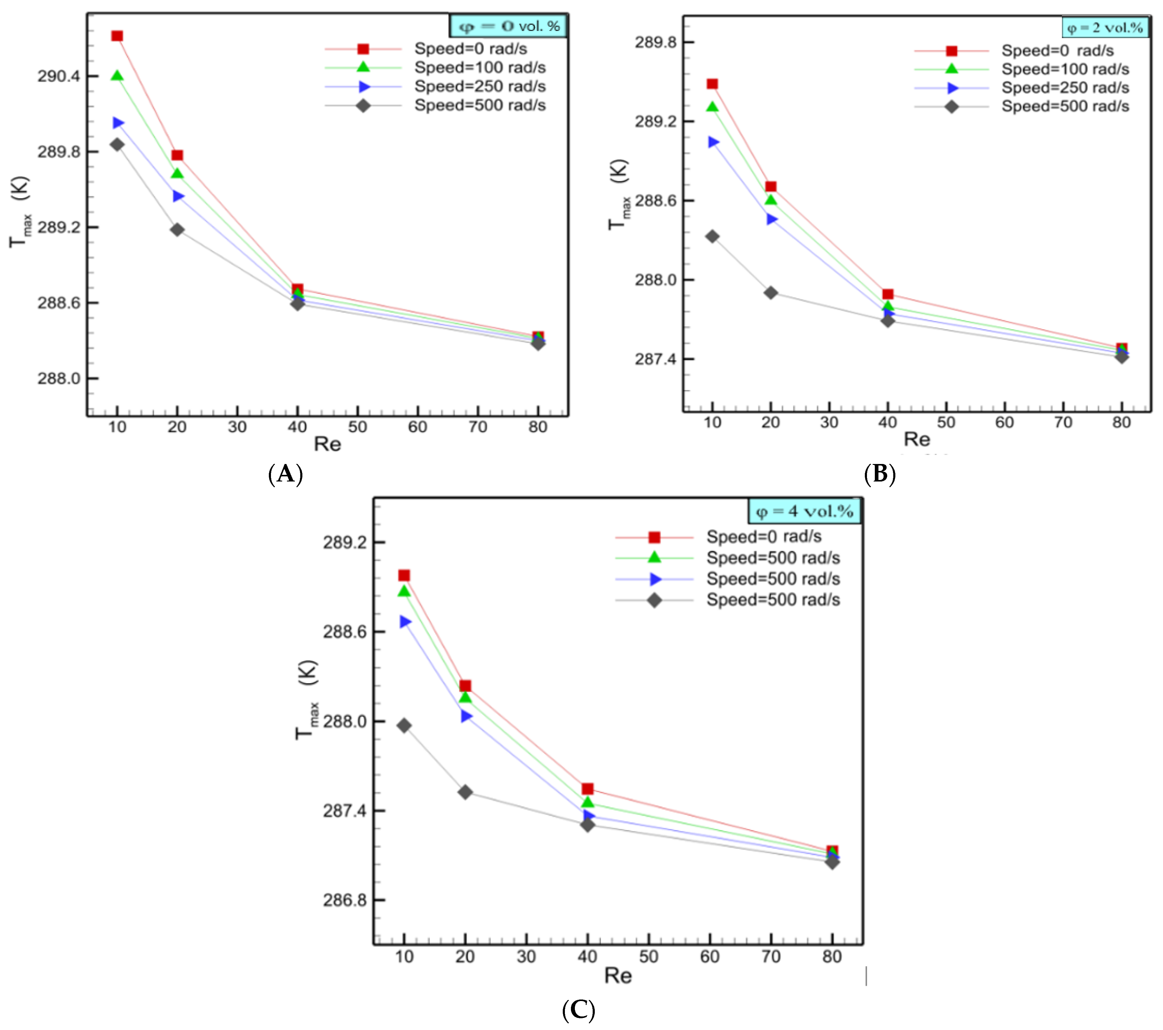
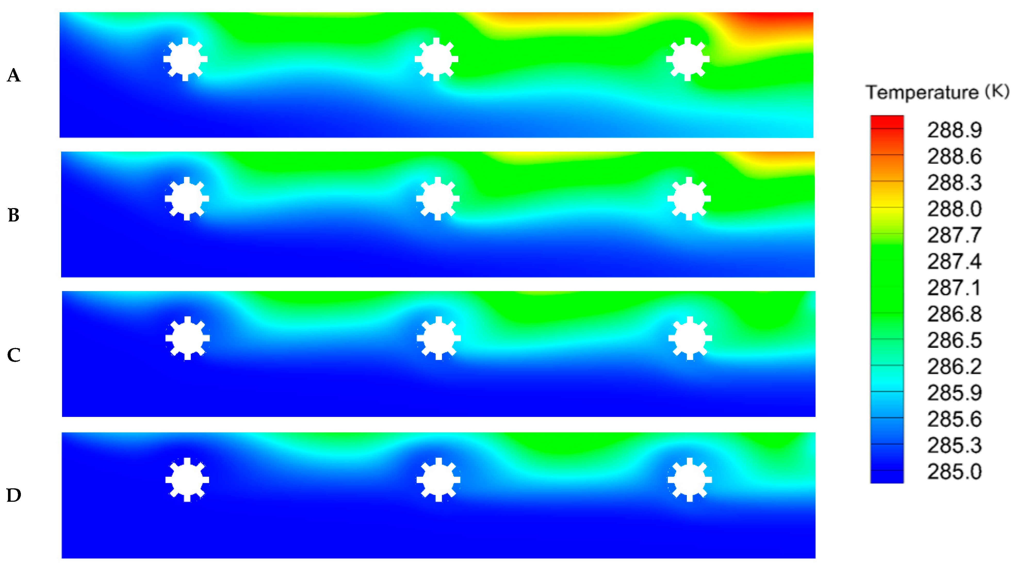
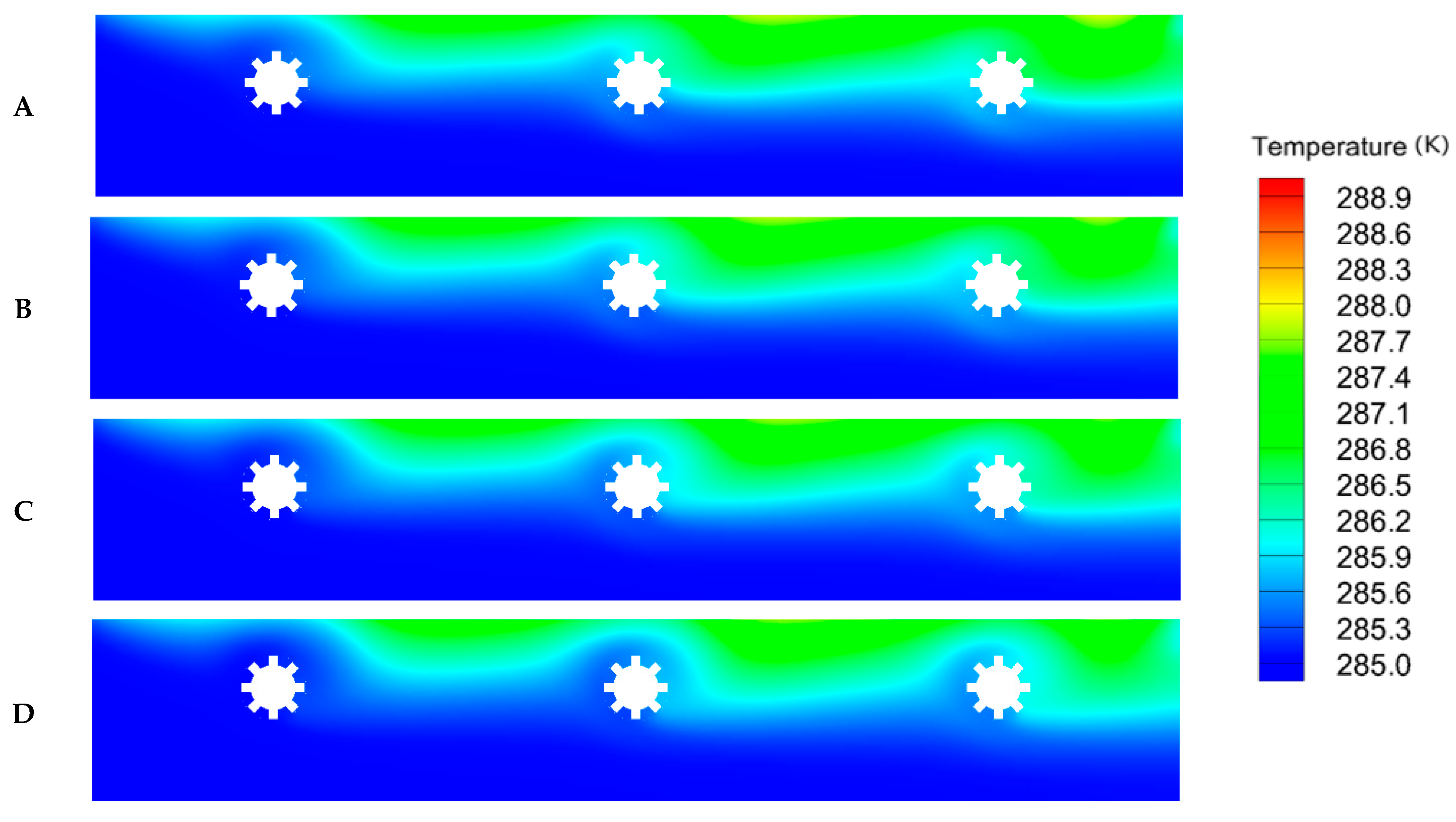
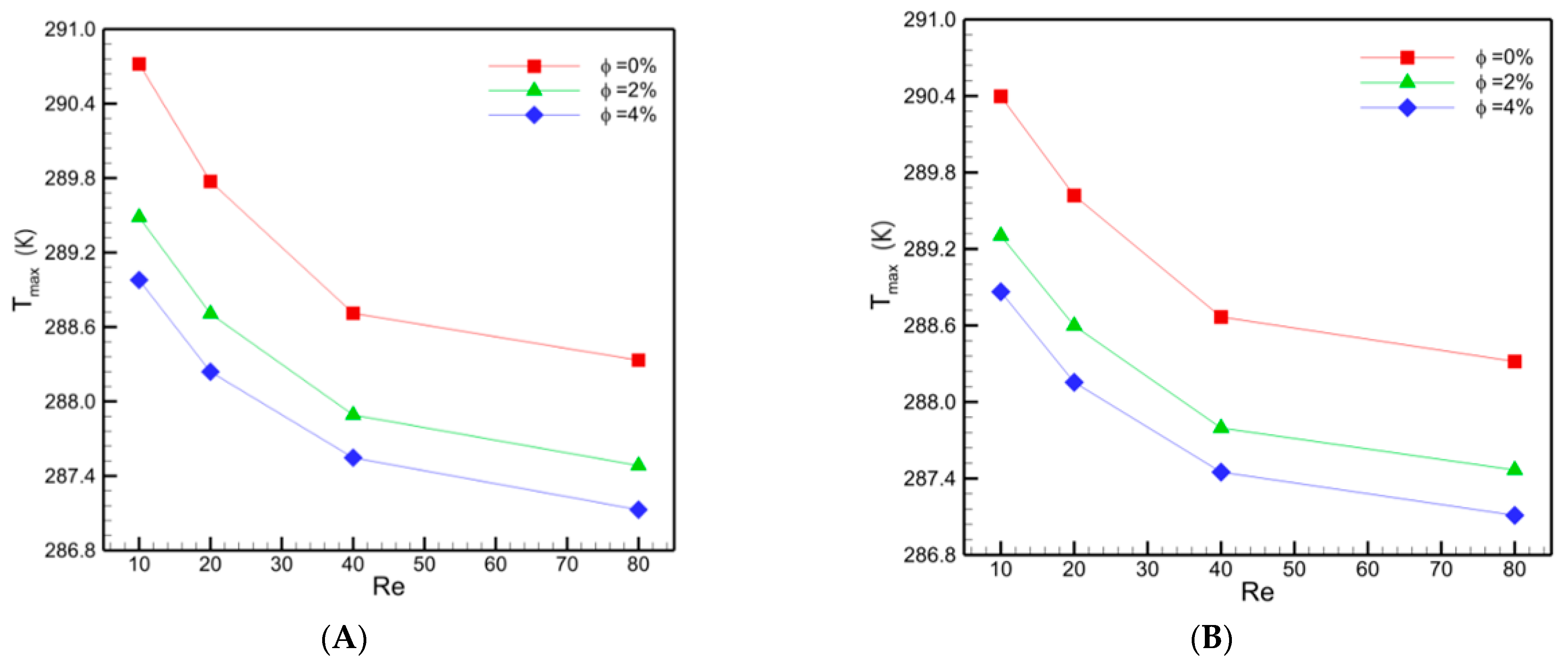
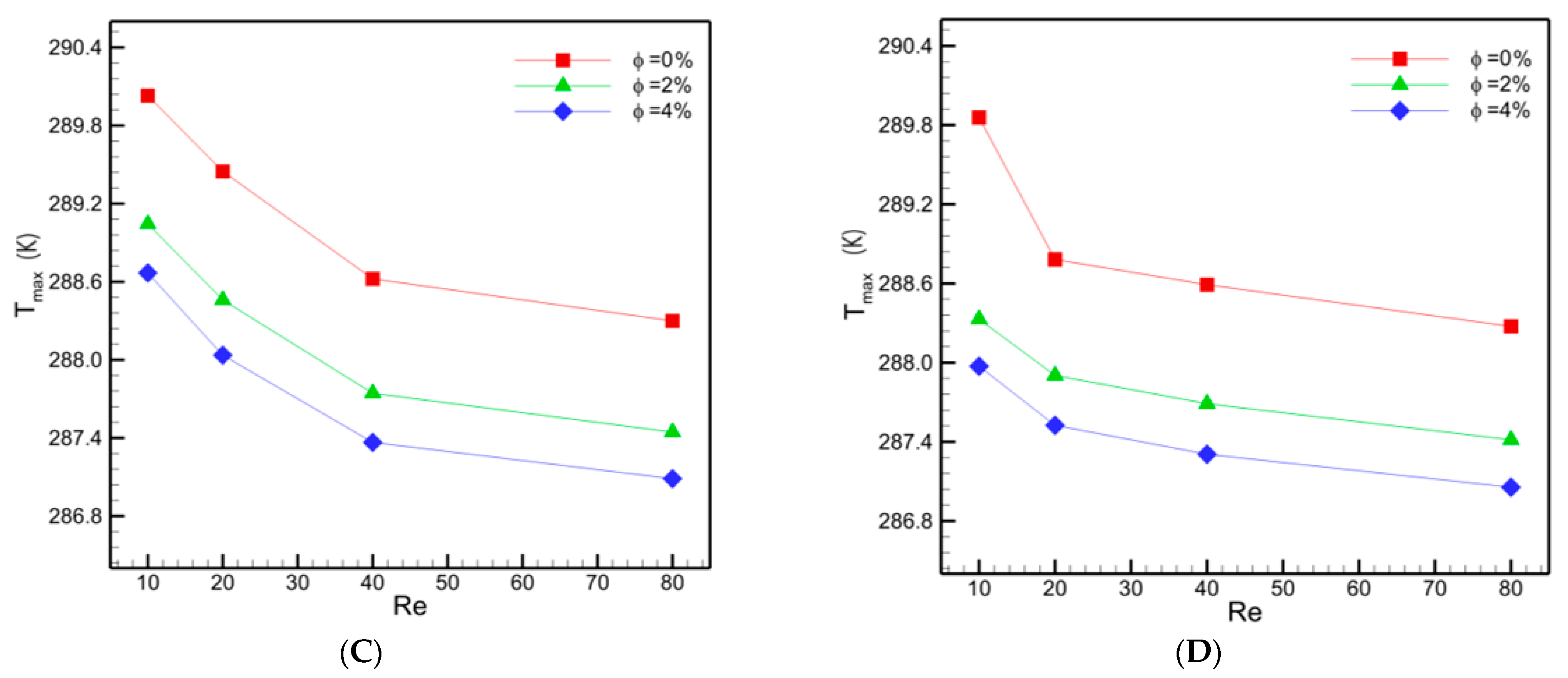
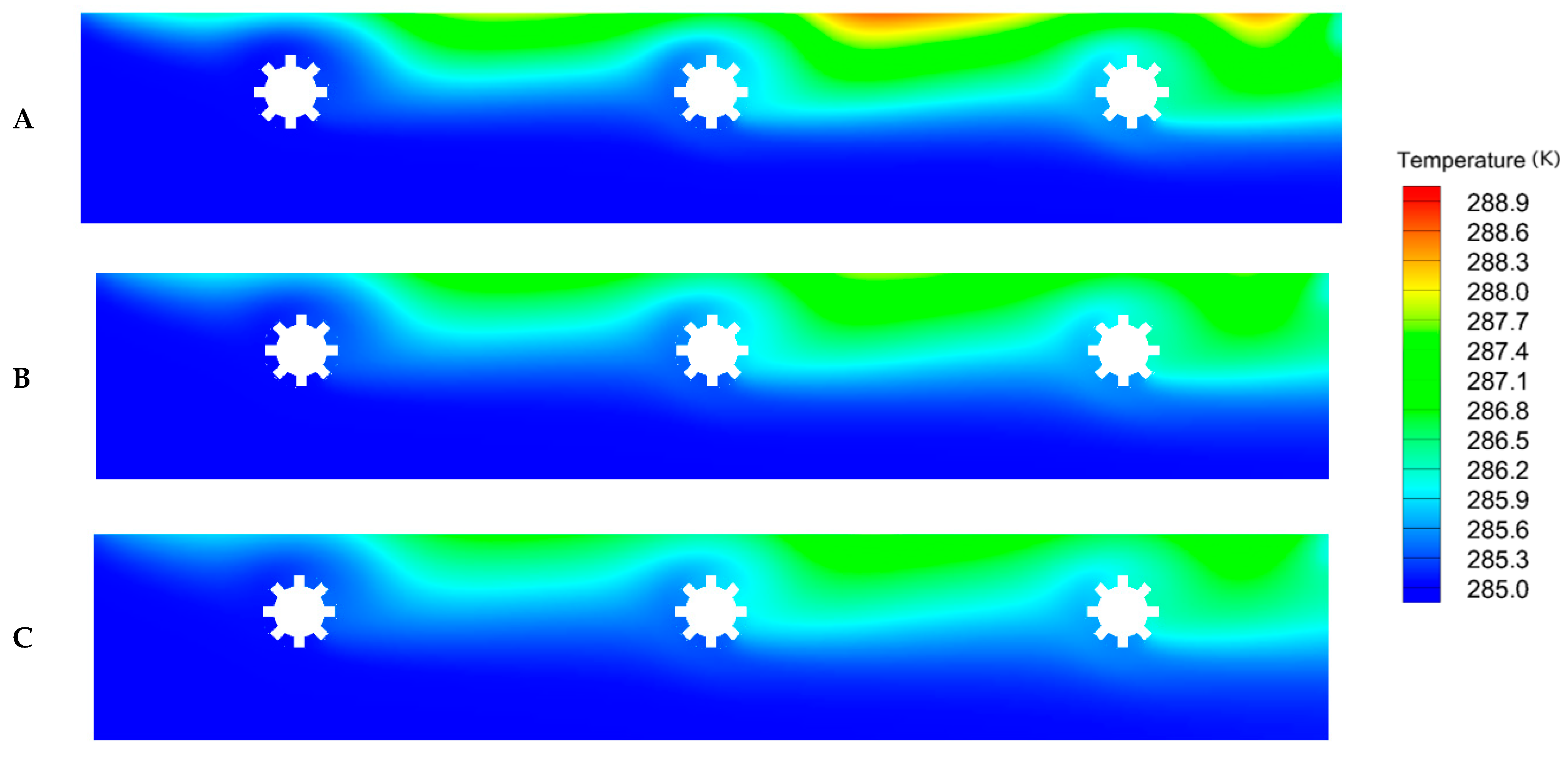
3.3. Maximum Temperature
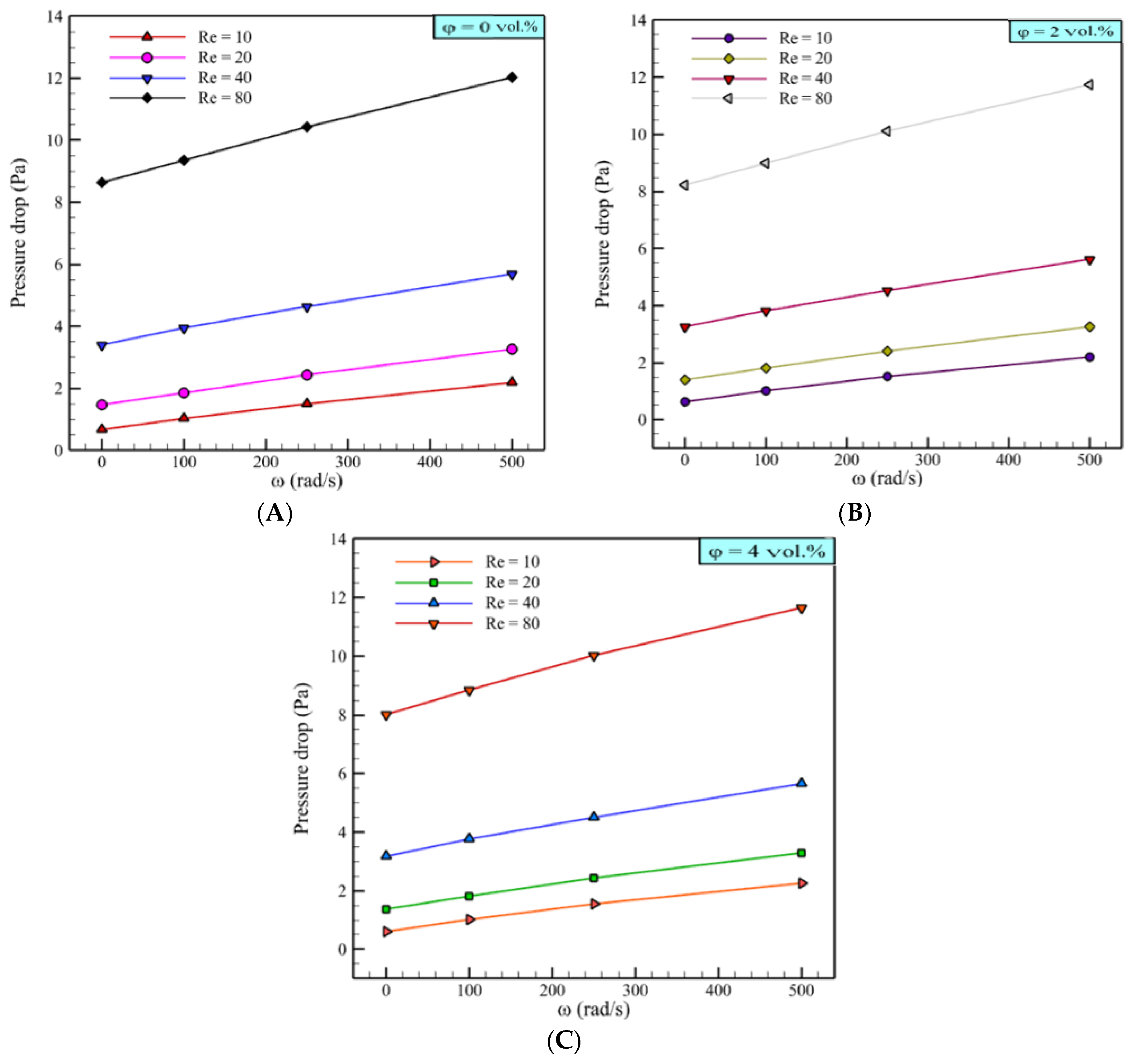
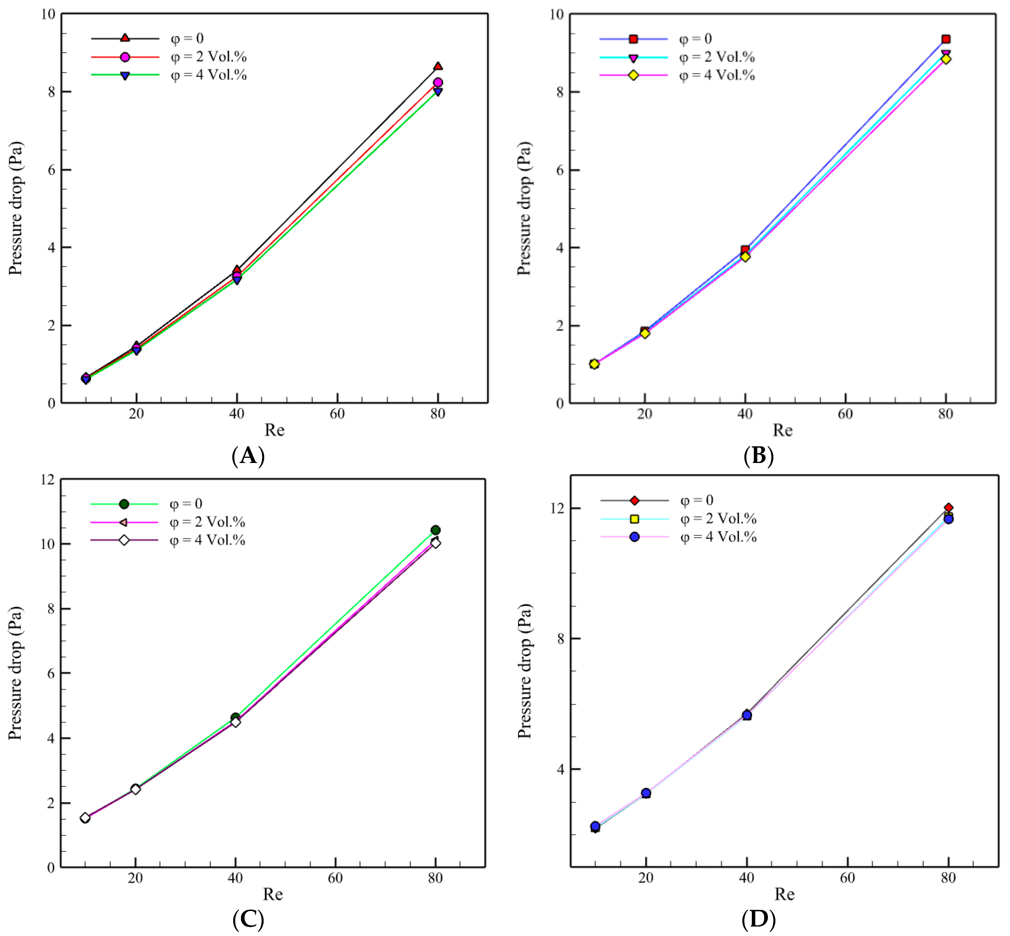
In Figure 11, the maximum temperature and the microchannel length are plotted for various Re numbers and rotation speeds. As shown, a higher Re could reduce the maximum temperature (Tmax). Since the nanofluid had a high HTC (as represented in Figure 5), it was expected that a lower Tmax would be observed for the nanofluids such that at φ = 4 vol.%, the lowest Tmax was recorded. Moreover, when increasing Re to 40, Tmax considerably decreased, while for Re > 40, Tmax gradually decreased. The effect of an increase in Re number between 10 and 40 was two times larger than the same effect at Reynolds numbers between 40 to 80. That being said, the rotating tubes could have a significant effect on the magnitude of Tmax. A higher rotation speed led to a lower Tmax. As mentioned above, however, at a lower Re, increasing the rotation speed decreased Tmax remarkably, while at a higher Re number, increasing ω had no significant effect on Tmax. This phenomenon is presented in Figure 12.
Figure 12 illustrates the temperature contours for nanofluids with φ = 2 vol.% for different Reynolds numbers at ω = 250 rad/s. The existence of the cold working fluid through the microchannel was higher by increasing Re; hence, the temperature distribution was more uniform when Re increased. Therefore, more heat was eliminated from the tube bundle; hence, the value of Tmax decreased. Although less fresh working fluid could reach the hot wall surface at low Re, the rotating tubes transferred more fresh fluid toward the wall. This phenomenon was more significant at higher Reynolds numbers.
The contours of the maximum temperature for nanofluids at φ = 2 vol.% at Re = 40 for various rotation speeds are displayed in Figure 13. It was found that by increasing the rotation speed from 0 to 500 rad/s, the tube bundle’s temperature distribution was enhanced. When the tubes were in a stationary condition, the most critical parameter controlling the heat transfer was the wall’s thermal boundary layer since the tubes’ rotation improved the fluid distribution inside the microchannel. Furthermore, the mixing induced by the recirculating fluid caused the thermal boundary layer thickness at the wall vicinity to decrease, thereby increasing the temperature gradient, and the heat transfer was intensified.
In Figure 14, the maximum temperature is represented as a function of Re for different nanofluid concentrations and rotation speeds. For both the stationary and rotating tubes, adding nanoparticles to the base fluid decreased Tmax. Moreover, two different behaviors were identified that could be used to explain the reduction in Tmax: (1) for ω = 0 rad/s to ω = 250 rad/s and (2) for ω = 250 rad/s to ω = 500 rad/s. Tmax descended with a drastic slope in the first regime by increasing Re from 10 to 40, followed by a gradual decrease from 40 to 80. Meanwhile, in the second regime, the gradual decrease shifted to Re = 20 such that it started from that Re. Similar behavior was identified for the cases of water and other nanofluids.
The isothermal contours of nanofluids and water for Re = 40 and ω = 250 rad/s are shown in Figure 15. As shown in Figure 15a, at some points near the hot wall, the temperature was ≈288.6 K. Meanwhile, by adding Cu nanoparticles to the base fluid, maximum temperatures of 287.7 K and 287.3 K were reached for 2% and 4% concentrations, respectively. It was identified that the higher thermal conductivity obtained for nanofluids had an intensive effect on promoting thermal energy transfer from the wall’s heat source. Furthermore, the fluid circulation prompted by the finned rotating tubes contributed to the heat transfer. Thus, adding nanoparticles, rotating tubes, and attaching fins improve the heat transfer mechanism and removed more thermal energy from the system.

3.4. Pressure Drop

The pressure drop as a function of rotation speed at various Re’s for water and nanofluids is depicted in Figure 16. By increasing the rotation speed, the pressure drop was augmented for all ranges of Re and both water and nanofluid. For example, at φ = vol.% and Re = 10, the pressure drop increased by 268% by changing the rotation speed from 0 to 500 rad/s. Meanwhile the pressure drop augmentation was 140.5%, 78.5%, and 45.3% for Re = 20, 40, and 80, respectively. Notably, at high Re numbers, the rotating tubes’ influence was insignificant by applying a rotation speed of up to 500 rad/s. Hence, the heat transfer coefficient and pressure drop were independent of the rotation speed. However, the further investigation also needs to identify the heat transfer mechanisms at high Re numbers for rotation speeds between 0 and 500 rad/s. Furthermore, for each concentration, increasing the Re augmented the pressure drop. At ω = 0 rad/s and φ = 4 vol.%, increasing Re from 10 to 20 led to a 123% augmentation in the pressure drop. The augmentations for Re = 20 to Re = 40 and Re = 40 to Re = 80 were 132% and 154%, respectively.
In Figure 17, pressure drop contours are depicted at Re = 40 and ω = 250 rad/s for water and nanofluids. The addition of nanoparticles had no remarkable effect on the pressure drop of the system. All three contours were almost in the same range of pressure values. As mentioned in Figure 16, in the microchannel with rotating tubes, the pressure generation’s primary resource was the fins’ rotation. Moreover, adding nanoparticles to the base fluid had a minimal effect, which can be neglected.
In Figure 18, the pressure drop is plotted as a function of Re for different nanoparticle concentrations and rotation speeds. The pressure drop increased when increasing the Reynolds number, and the value of the pressure drop was the same for water and nanofluids. The difference between the pressure drop of water and nanofluids was more noticeable at slower rotation speeds. The significant pressure drop along the microchannel was determined by contacting the fluid flow with tubes and the circulated flow around the tubes. As indicated in Figure 11, a high-pressure area was generated between the main fluid flow and the circulated flow surrounding the rotating tube. Since the fluid cohesion was low, the streamlines of the circulated flow were more irregular. Therefore, the interactions increased, and the pressure drop value was augmented. Meanwhile, fluid with high cohesion (a nanofluid has higher cohesion due to its higher dynamic viscosity) had more arranged streamlines around the tube; therefore, less fluid from the main flow can penetrate it. Subsequently, the pressure drop of the nanofluid could be reduced in comparison to water. However, this reduction could be somewhat suppressed by the pressure drop that originated from increased dynamic viscosity. This conclusion shows that nanofluids can be used in rotating systems without applying any pressure drop value penalties.

4. Conclusions

A numerical investigation was conducted to analyze the heat transfer and pressure drop of a finned rotating tube bundle in this study. A microchannel was simulated in which six tubes rotated, along with their attached fins. Furthermore, distilled water, as well as Cu/water nanofluid containing 2 vol.% and 4 vol.% concentrations, were considered the working fluids. The outputs were presented in comparison with the water outcomes. The substantial results are summarized as follows:
  • Rotating tubes significantly affected the hydrodynamics of the tube bundle, which was installed inside the microchannel. Vortexes induced by the rotating tubes caused the fluid flow to transfer more thermal energy. A maximum heat transfer enhancement of 34.2% was achieved at Re = 10 by increasing the rotation speed from 0 to 500 rad/s.
  • For all ranges of nanofluid concentrations and at high Re, increasing the rotation speed from 0 to 500 rad/s had no remarkable effect on the heat transfer and maximum temperature. The heat transfer enhancement was 6% at Re = 80.
  • Adding nanoparticles to the base fluid noticeably enhanced the heat transfer coefficient. A maximum heat transfer enhancement of 42.3% was gained by adding 4 vol.% Cu nanoparticles at Re = 80 and ω = 500 rad/s.
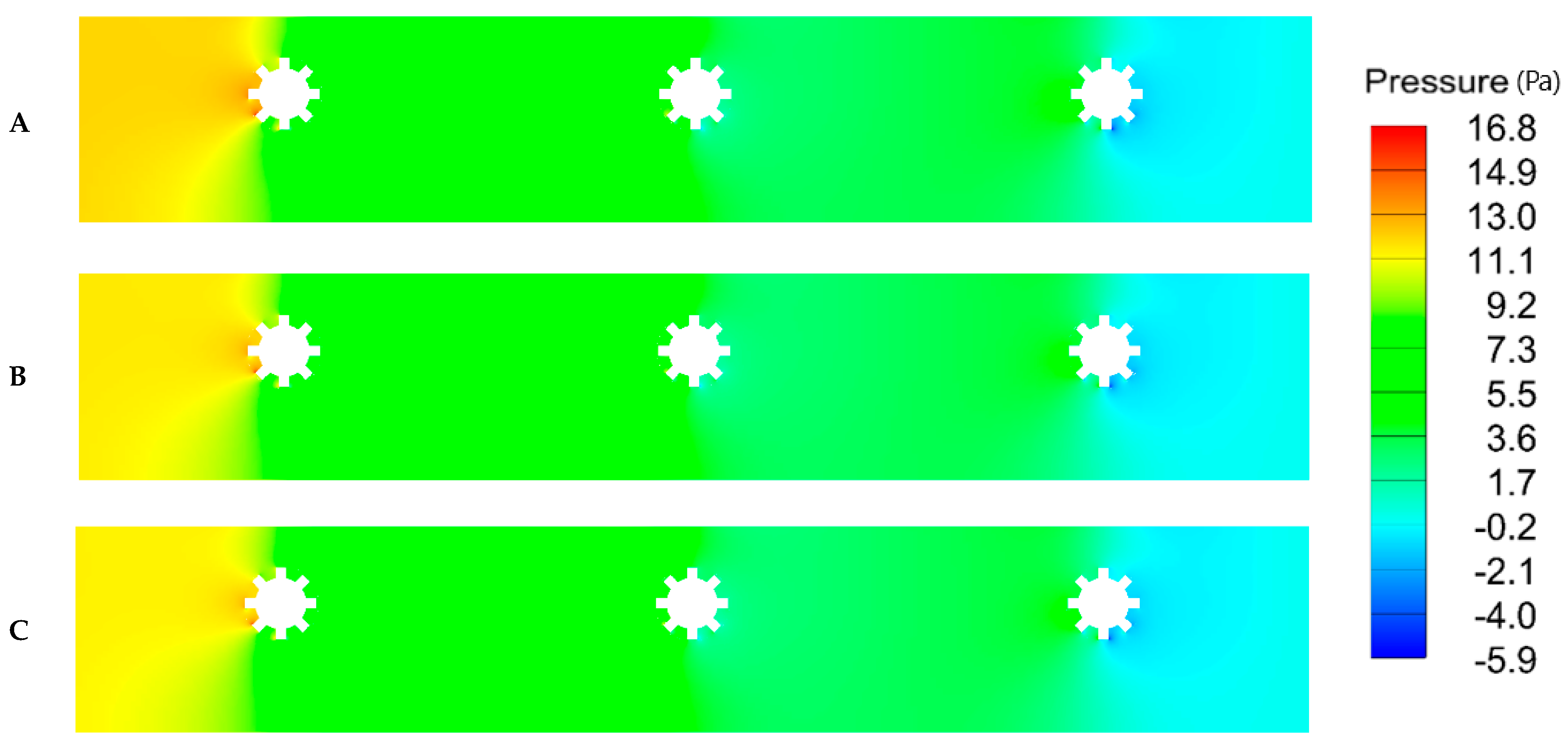
  • Rotating tubes generated a pressure drop through the microchannel. This was due to the fluid interaction caused by the fins.
  • As a significant outcome, adding nanoparticles had no pressure drop augmentation. Nevertheless, a higher nanofluid concentration had a slightly lower pressure drop.
  • At high Re, the pressure drop and heat transfer remained almost unchanged by applying rotation to the tube bundle.

Author Contributions

Conceptualization, M.A.A. and M.R.S.; methodology, M.R.S.; software, M.R.S.; validation, M.A.A. and M.R.S.; formal analysis, M.R.S.; investigation, M.A.A.; resources, M.A.A.; visualization, M.A.A. and M.R.S.; data curation, M.A.A.; writing—original draft preparation, M.A.A. and M.R.S.; writing—review and editing, M.A.A. and M.R.S.; supervision, M.A.A.; project administration, M.R.S.; funding acquisition, M.A.A. All authors have read and agreed to the published version of the manuscript.

Funding

This work was funded by the Deanship of Scientific Research (DSR), King Abdulaziz University, Jeddah, under grant no. D-071-135-1442. The authors, therefore, gratefully acknowledge the DSR’s technical and financial support.

Institutional Review Board Statement

Not applicable.

Informed Consent Statement

Not applicable.

Data Availability Statement

Not applicable.

Conflicts of Interest

The authors declare that there is no conflict of interest regarding the publication of this paper.

Nomenclature

x, y, zCartesian coordinates (m)
nNumber of phases
NuNusselt number
PPressure (N·m−2)
ReReynolds number
hkSensible enthalpy for phase k (J·kg−1)
CpSpecific heat capacity (J·kg−1·K−1)
TTemperature (K)
tTime (s)
kThermal conductivity (W·m−1·K−1)
VVelocity (m·s−1)
hHeat transfer coefficient (W·m−2·K−1)
DeHydraulic diameter (m)
PtTube pitch (m)
DDiameter (m)
LLength (m)

Greek Symbols

pDensity (kg·m−3)
μDynamic viscosity (Pa·s)
φVolume fraction of nanoparticles
ωRotation speed (rad/s)

Subscripts

effEffective
ZIndices
mMixture
pParticle
fFluid

References

  1. Kaviany, M. Heat Transfer Physics; Cambridge University Press: Cambridge, UK, 2014. [Google Scholar]
  2. Rozati, S.A.; Montazerifar, F.; Akbari, O.A.; Hoseinzadeh, S.; Nikkhah, V.; Marzban, A.; Abdolvand, H.; Goodarzi, M. Natural convection heat transfer of water/Ag nanofluid inside an elliptical enclosure with different attack angles. Math. Methods Appl. Sci. 2020, 1–18. [Google Scholar] [CrossRef]
  3. Bakthavatchalam, B.; Habib, K.; Saidur, R.; Saha, B.B.; Irshad, K. Comprehensive study on nanofluid and ionanofluid for heat transfer enhancement: A review on current and future perspective. J. Mol. Liq. 2020, 305, 112787. [Google Scholar] [CrossRef]
  4. Pandya, N.S.; Shah, H.; Molana, M.; Tiwari, A.K. Heat transfer enhancement with nanofluids in plate heat exchangers: A comprehensive review. Eur. J. Mech. B/Fluids 2020, 81, 173–190. [Google Scholar] [CrossRef]
  5. Hale, N.W., Jr.; Viskanta, R. Solid-liquid phase-change heat transfer and interface motion in materials cooled or heated from above or below. Int. J. Heat Mass Transf. 1980, 23, 283–292. [Google Scholar] [CrossRef]
  6. Reddy, J.R.; Sugunamma, V.; Sandeep, N. Thermophoresis and Brownian motion effects on unsteady MHD nanofluid flow over a slendering stretching surface with slip effects. Alex. Eng. J. 2018, 57, 2465–2473. [Google Scholar] [CrossRef]
  7. Akbari, O.A.; Afrouzi, H.H.; Marzban, A.; Toghraie, D.; Malekzade, H.; Arabpour, A. Investigation of volume fraction of nanoparticles effect and aspect ratio of the twisted tape in the tube. J. Therm. Anal. Calorim. 2017, 129, 1911–1922. [Google Scholar] [CrossRef]
  8. Choi, S.U.S.; Eastman, J.A. Enhancing thermal conductivity of fluids with nanoparticles. In Proceedings of the 1995 International mechanical engineering congress and exhibition, San Francisco, CA, USA, 12–17 November 1995. [Google Scholar]
  9. Harish, R.; Sivakumar, R. Effects of nanoparticle dispersion on turbulent mixed convection flows in cubical enclosure considering Brownian motion and thermophoresis. Powder Technol. 2021, 378, 303–316. [Google Scholar] [CrossRef]
  10. Abdollahi-Moghaddam, M.; Motahari, K.; Rezaei, A. Performance characteristics of low concentrations of CuO/water nanofluids flowing through horizontal tube for energy efficiency purposes; an experimental study and ANN modeling. J. Mol. Liq. 2018, 271, 342–352. [Google Scholar] [CrossRef]
  11. Hong, Y.; Du, J.; Li, Q.; Xu, T.; Li, W. Thermal-hydraulic performances in multiple twisted tapes inserted sinusoidal rib tube heat exchangers for exhaust gas heat recovery applications. Energy Convers. Manag. 2019, 185, 271–290. [Google Scholar] [CrossRef]
  12. Ocłoń, P.; Łopata, S.; Stelmach, T.; Li, M.; Zhang, J.-F.; Mzad, H.; Tao, W.-Q. Design optimization of a high-temperature fin-and-tube heat exchanger manifold—A case study. Energy 2021, 215, 119059. [Google Scholar] [CrossRef]
  13. Sadeghianjahromi, A.; Wang, C.-C. Heat transfer enhancement in fin-and-tube heat exchangers—A review on different mechanisms. Renew. Sustain. Energy Rev. 2021, 137, 110470. [Google Scholar] [CrossRef]
  14. Sözen, A.; Variyenli, H.I.; Özdemir, M.B.; Gürü, M.; Aytaç, İ. Heat transfer enhancement using alumina and fly ash nanofluids in parallel and cross-flow concentric tube heat exchangers. J. Energy Inst. 2016, 89, 414–424. [Google Scholar] [CrossRef]
  15. Sajid, M.U.; Ali, H.M. Recent advances in application of nanofluids in heat transfer devices: A critical review. Renew. Sustain. Energy Rev. 2019, 103, 556–592. [Google Scholar] [CrossRef]
  16. Said, Z.; Rahman, S.; Assad, M.E.H.; Alami, A.H. Heat transfer enhancement and life cycle analysis of a Shell-and-Tube Heat Exchanger using stable CuO/water nanofluid. Sustain. Energy Technol. Assess. 2019, 31, 306–317. [Google Scholar] [CrossRef]
  17. Sarafraz, M.M. Experimental investigation on pool boiling heat transfer to formic acid, propanol and 2-butanol pure liquids under the atmospheric pressure. J. Appl. Fluid Mech. 2013, 6, 73–79. [Google Scholar]
  18. Sarafraz, M.; Hormozi, F. Application of thermodynamic models to estimating the convective flow boiling heat transfer coefficient of mixtures. Exp. Therm. Fluid Sci. 2014, 53, 70–85. [Google Scholar] [CrossRef]
  19. Li, Z.; Mazinani, A.; Hayat, T.; Al-Rashed, A.A.; Alsulami, H.; Goodarzi, M.; Sarafraz, M. Transient pool boiling and particulate deposition of copper oxide nano-suspensions. Int. J. Heat Mass Transf. 2020, 155, 119743. [Google Scholar] [CrossRef]
  20. Li, Z.; Sarafraz, M.M.; Mazinani, A.; Hayat, T.; Alsulami, H.; Goodarzi, M. Pool boiling heat transfer to CuO-H2O nanofluid on finned surfaces. Int. J. Heat Mass Transf. 2020, 156, 119780. [Google Scholar] [CrossRef]
  21. Mehta, K.S.; Kundan, L.; Mallick, S.S. A Study on Heat Transfer and Pressure Drop in a Turbulent Flow Regime of Thermally Insulated and Conducting Nanofluids. J. Nanofluids 2019, 8, 490–499. [Google Scholar] [CrossRef]
  22. Zheng, M.; Han, D.; Asif, F.; Si, Z. Effect of Al2O3/water nanofluid on heat transfer of turbulent flow in the inner pipe of a double-pipe heat exchanger. Heat Mass Transf. 2019, 56, 1127–1140. [Google Scholar] [CrossRef]
  23. Sharafeldin, M.; Gróf, G. Efficiency of evacuated tube solar collector using WO3/Water nanofluid. Renew. Energy 2019, 134, 453–460. [Google Scholar] [CrossRef]
  24. Sadeghi, G.; Safarzadeh, H.; Ameri, M. Experimental and numerical investigations on performance of evacuated tube solar collectors with parabolic concentrator, applying synthesized Cu2O/distilled water nanofluid. Energy Sustain. Dev. 2019, 48, 88–106. [Google Scholar] [CrossRef]
  25. Arora, S.; Fekadu, G.; Subudhi, S. Energy and Exergy Analysis of Marquise Shaped Channel Flat Plate Solar Collector Using Al2O3—Water Nanofluid and Water. J. Sol. Energy Eng. 2019, 141. [Google Scholar] [CrossRef]
  26. Khanlari, A.; Sözen, A.; Variyenli, H.I.; Gürü, M. Comparison between heat transfer characteristics of TiO2/deionized water and kaolin/deionized water nanofluids in the plate heat exchanger. Heat Transf. Res. 2019, 50, 435–450. [Google Scholar] [CrossRef]
  27. Subramanian, R.; Kumar, A.S.; Vinayagar, K.; Muthusamy, C. Experimental analyses on heat transfer performance of TiO2–water nanofluid in double-pipe counter-flow heat exchanger for various flow regimes. J. Therm. Anal. Calorim. 2019, 140, 603–612. [Google Scholar] [CrossRef]
  28. Anvari, A.R.; Javaherdeh, K.; Emami-Meibodi, M. Investigation of Heat Transfer and Pressure Drop of Non-Newtonian Nanofluid Performance Through Micro Channels Heat Exchanger (MCHE) in Cross-Flow Configuration. J. Nanofluids 2019, 8, 631–639. [Google Scholar] [CrossRef]
  29. Mahay, N.; Yadav, R.K. An experimental investigation into heat transfer characteristics of aqua based Cu nanofluid for automobile radiator. In Proceedings of the 2nd International Conference on New Frontiers in Engineering, Science & Technology (NFEST), Kurukshetra, India, 18–22 February 2019; Volume 1240, p. 012043. [Google Scholar]
  30. Jadar, R.; Shashishekar, K.; Manohara, S. Performance Evaluation of Al-MWCNT based Automobile Radiator. Mater. Today Proc. 2019, 9, 380–388. [Google Scholar] [CrossRef]
  31. Maisuria, M.B.; Sonar, D.M.; Rathod, M.K.; Bhatt, M.K. Experimental and analytical investigation on an automobile radiator with CuO/EG-water based nanofluid as coolant. Heat Transfer-Asian Res. 2019, 48, 2596–2612. [Google Scholar] [CrossRef]
  32. Pourfayaz, F.; Imani, M.; Mehrpooya, M.; Shirmohammadi, R. Process development and exergy analysis of a novel hybrid fuel cell-absorption refrigeration system utilizing nanofluid as the absorbent liquid. Int. J. Refrig. 2019, 97, 31–41. [Google Scholar] [CrossRef]
  33. Selimefendigil, F.; Öztop, H.F. Effects of a rotating tube bundle on the hydrothermal performance for forced convection in a vented cavity with Ag-MgO/water hybrid and CNT-water nanofluids. J. Therm. Anal. Calorim. 2020, 1–18. [Google Scholar] [CrossRef]
  34. Selimefendigil, F.; Öztop, H.F. Numerical analysis and ANFIS modeling for mixed convection of CNT-water nanofluid filled branching channel with an annulus and a rotating inner surface at the junction. Int. J. Heat Mass Transf. 2018, 127, 583–599. [Google Scholar] [CrossRef]
  35. Barnoon, P.; Toghraie, D.; Dehkordi, R.B.; Abed, H. MHD mixed convection and entropy generation in a lid-driven cavity with rotating cylinders filled by a nanofluid using two phase mixture model. J. Magn. Magn. Mater. 2019, 483, 224–248. [Google Scholar] [CrossRef]
  36. Khan, S.; Zou, R.; Yu, A. Computational simulation of air-side heat transfer and pressure drop performance in staggered mannered twisted oval tube bundle operating in cross-flow. Int. J. Therm. Sci. 2021, 161, 106748. [Google Scholar] [CrossRef]
  37. Khanafer, K.; Aithal, S.; Vafai, K. Mixed convection heat transfer in a differentially heated cavity with two rotating cylinders. Int. J. Therm. Sci. 2019, 135, 117–132. [Google Scholar] [CrossRef]
  38. Selimefendigil, F.; Öztop, H.F. Hydro-thermal performance of CNT nanofluid in double backward facing step with rotating tube bundle under magnetic field. Int. J. Mech. Sci. 2020, 185, 105876. [Google Scholar] [CrossRef]
  39. Marzban, A.; Sheikhzadeh, G.; Toghraie, D. Laminar flow and heat transfer of water/NDG nanofluid on tube banks with rhombic cross section with different longitudinal arrangements. J. Therm. Anal. Calorim. 2019, 140, 427–437. [Google Scholar] [CrossRef]
  40. Garmroodi, M.D.; Ahmadpour, A.; Talati, F. MHD mixed convection of nanofluids in the presence of multiple rotating cylinders in different configurations: A two-phase numerical study. Int. J. Mech. Sci. 2019, 150, 247–264. [Google Scholar] [CrossRef]
  41. Motahari, K.; Moghaddam, M.A.; Moradian, M. Experimental investigation and development of new correlation for influences of temperature and concentration on dynamic viscosity of MWCNT-SiO2 (20–80)/20W50 hybrid nano-lubricant. Chin. J. Chem. Eng. 2018, 26, 152–158. [Google Scholar] [CrossRef]
  42. Akbari, O.A.; Safaei, M.R.; Goodarzi, M.; Akbar, N.S.; Zarringhalam, M.; Shabani, G.A.S.; Dahari, M. A modified two-phase mixture model of nanofluid flow and heat transfer in a 3-D curved microtube. Adv. Powder Technol. 2016, 27, 2175–2185. [Google Scholar] [CrossRef]
  43. Brinkman, H.C. The Viscosity of Concentrated Suspensions and Solutions. J. Chem. Phys. 1952, 20, 571. [Google Scholar] [CrossRef]
  44. Xuan, Y.; Li, Q. Investigation on Convective Heat Transfer and Flow Features of Nanofluids. J. Heat Transf. 2003, 125, 151–155. [Google Scholar] [CrossRef] [Green Version]
  45. Chon, C.H.; Kihm, K.D.; Lee, S.P.; Choi, S.U.S. Empirical correlation finding the role of temperature and particle size for nanofluid (Al2O3) thermal conductivity enhancement. Appl. Phys. Lett. 2005, 87, 153107. [Google Scholar] [CrossRef]
  46. Mintsa, H.A.; Roy, G.; Nguyen, C.T.; Doucet, D. New temperature dependent thermal conductivity data for water-based nanofluids. Int. J. Therm. Sci. 2009, 48, 363–371. [Google Scholar] [CrossRef]
  47. Goodarzi, M.; Safaei, M.; Vafai, K.; Ahmadi, G.; Dahari, M.; Kazi, S.; Jomhari, N. Investigation of nanofluid mixed convection in a shallow cavity using a two-phase mixture model. Int. J. Therm. Sci. 2014, 75, 204–220. [Google Scholar] [CrossRef]
  48. Karimipour, A.; Nezhad, A.H.; Behzadmehr, A.; Alikhani, S.; Abedini, E. Periodic mixed convection of a nanofluid in a cavity with top lid sinusoidal motion. Proc. Inst. Mech. Eng. Part C J. Mech. Eng. Sci. 2011, 225, 2149–2160. [Google Scholar] [CrossRef] [Green Version]
  49. Dadsetani, R.; Salimpour, M.R.; Tavakoli, M.R.; Goodarzi, M.; Filho, E.P.B. Thermal and mechanical design of reverting microchannels for cooling disk-shaped electronic parts using constructal theory. Int. J. Numer. Methods Heat Fluid Flow 2019, 30, 245–265. [Google Scholar] [CrossRef]
  50. Patankar, S.V. Numerical Heat Transfer and Fluid Flow; CRC Press: Boca Raton, FL, USA, 2018. [Google Scholar]
  51. Abdulrazzaq, T.; Togun, H.; Goodarzi, M.; Kazi, S.N.; Ariffin, M.K.A.; Adam, N.M.; Hooman, K. Turbulent heat transfer and nanofluid flow in an annular cylinder with sudden reduction. J. Therm. Anal. Calorim. 2020, 141, 373–385. [Google Scholar] [CrossRef]
  52. Mat, M.N.H.; Asmuin, N.Z.; Basir, F.M.; Goodarzi, M.; Rahman, M.F.A.; Khairulfuaad, R.; Jabbar, B.A.; Kasihmuddin, M.S.M. Influence of divergent length on the gas-particle flow in dual hose dry ice blasting nozzle geometry. Powder Technol. 2020, 364, 152–158. [Google Scholar] [CrossRef]
  53. Truesdell, C.; Toupin, R. The classical field theories. In Principles of Classical Mechanics and Field Theory/Prinzipien der Klassischen Mechanik und Feldtheorie; Springer: Berlin/Heidelberg, Germany, 1960; pp. 226–858. [Google Scholar]
  54. Eringen, A.; Ingram, J.D. A Continuum theory of chemically reacting media—I. Int. J. Eng. Sci. 1965, 3, 197–212. [Google Scholar] [CrossRef]
  55. Drumheller, D.S.; Bedford, A. A thermomechanical theory for reacting immiscible mixtures. Arch. Ration. Mech. Anal. 1980, 73, 257–284. [Google Scholar] [CrossRef]
  56. Abu-Zaid, S.; Ahmadi, G. A thermodynamically consistent rate-dependent model for turbulent two-phase flows. Int. J. Non-linear Mech. 1995, 30, 509–529. [Google Scholar] [CrossRef]
  57. Ahmadi, G. On mechanics of saturated granular materials. Int. J. Non-linear Mech. 1980, 15, 251–262. [Google Scholar] [CrossRef]
  58. Ahmadi, G. On the mechanics of incompressible multiphase suspensions. Adv. Water Resour. 1987, 10, 32–43. [Google Scholar] [CrossRef]
  59. Ahmadi, G.; Cao, J.; Schneider, L.; Sadiki, A. A thermodynamical formulation for chemically active multiphase turbulent flows. Int. J. Eng. Sci. 2006, 44, 699–720. [Google Scholar] [CrossRef] [Green Version]
  60. Ahmadi, G.; Ma, D. A thermodynamical formulation for dispersed multiphase turbulent flows—1: Basic theory. Int. J. Multiph. Flow 1990, 16, 323–340. [Google Scholar] [CrossRef]
  61. Behzadmehr, A.; Saffar-Avval, M.; Galanis, N. Prediction of turbulent forced convection of a nanofluid in a tube with uniform heat flux using a two phase approach. Int. J. Heat Fluid Flow 2007, 28, 211–219. [Google Scholar] [CrossRef]
  62. Bahiraei, M.; Heshmatian, S.; Goodarzi, M.; Moayedi, H. CFD analysis of employing a novel ecofriendly nanofluid in a miniature pin fin heat sink for cooling of electronic components: Effect of different configurations. Adv. Powder Technol. 2019, 30, 2503–2516. [Google Scholar] [CrossRef]
  63. Arasteh, H.; Mashayekhi, R.; Goodarzi, M.; Motaharpour, S.H.; Dahari, M.; Toghraie, D. Heat and fluid flow analysis of metal foam embedded in a double-layered sinusoidal heat sink under local thermal non-equilibrium condition using nanofluid. J. Therm. Anal. Calorim. 2019, 138, 1461–1476. [Google Scholar] [CrossRef]
  64. Yousefzadeh, S.; Rajabi, H.; Ghajari, N.; Sarafraz, M.M.; Akbari, O.A.; Goodarzi, M. Numerical investigation of mixed convection heat transfer behavior of nanofluid in a cavity with different heat transfer areas. J. Therm. Anal. Calorim. 2020, 140, 2779–2803. [Google Scholar] [CrossRef]
  65. Bagherzadeh, S.A.; Jalali, E.; Sarafraz, M.M.; Akbari, O.A.; Karimipour, A.; Goodarzi, M.; Bach, Q.-V. Effects of magnetic field on micro cross jet injection of dispersed nanoparticles in a microchannel. Int. J. Numer. Methods Heat Fluid Flow 2019, 30, 2683–2704. [Google Scholar] [CrossRef]
  66. Roache, P.J. Perspective: A Method for Uniform Reporting of Grid Refinement Studies. J. Fluids Eng. 1994, 116, 405–413. [Google Scholar] [CrossRef]
  67. Sosnowski, M. Evaluation of Heat Transfer Performance of a Multi-Disc Sorption Bed Dedicated for Adsorption Cooling Technology. Energies 2019, 12, 4660. [Google Scholar] [CrossRef] [Green Version]
  68. Ghazanfarian, J.; Nobari, M. A numerical study of convective heat transfer from a rotating cylinder with cross-flow oscillation. Int. J. Heat Mass Transf. 2009, 52, 5402–5411. [Google Scholar] [CrossRef]
  69. Vermahmoudi, Y.; Peyghambarzadeh, S.M.; Hashemabadi, S.H.; Naraki, M. Experimental investigation on heat transfer performance of Fe2O3/water nanofluid in an air-finned heat exchanger. Eur. J. Mech. B/Fluids 2014, 44, 32–41. [Google Scholar] [CrossRef]
Figure 1. (A) Tube bundle configuration, (B) fin dimensions, and (C) symmetrical tube bundle dimensions.
Mathematics 09 01153 g001
Figure 2. The developed mesh structure that was used in the computational domain.
Mathematics 09 01153 g002
Figure 3. Comparison of overall heat transfer coefficient of 0.65 vol.% water/iron (III) oxide nanofluid at Qair = 1009 with the results of Vermahmoudi et al. [69].
Mathematics 09 01153 g003
Figure 4. (A) Heat transfer coefficient and (B) pressure drop for φ = 4 vol.% and different flow directions.
Mathematics 09 01153 g004
Figure 5. Heat transfer coefficient versus Re at diverse concentrations for (A) ω = 0 rad/s, (B) ω = 100 rad/s, (C) ω = 250 rad/s, and (D) ω = 500 rad/s.
Mathematics 09 01153 g005aMathematics 09 01153 g005b
Figure 6. Velocity contours at Re = 40 and ω = 250 rad/s for (A) water, (B) 2 vol.% nanofluid, and (C) 4 vol.% nanofluid.
Mathematics 09 01153 g006aMathematics 09 01153 g006b
Figure 7. Heat transfer coefficient versus Re at different rotation speeds for (A) φ = 0 vol.%, (B) φ = 2 vol.%, and (C) φ = 4 vol.%.
Mathematics 09 01153 g007aMathematics 09 01153 g007b
Figure 8. Heat transfer coefficient versus rotation speed at different Re’s for (A) φ = 0 vol.%, (B) φ = 2 vol.%, and (C) φ = 4 vol.%.
Mathematics 09 01153 g008aMathematics 09 01153 g008b
Figure 9. Velocity contours with Re = 40 and φ = 2 vol.% for (A) ω = 0 rad/s, (B) ω = 100 rad/s, (C) ω = 250 rad/s, and (D) ω = 500 rad/s.
Mathematics 09 01153 g009
Figure 10. Streamlines for a nanofluid with 2 vol.% concentration, Re = 40, and ω = 500 rad/s: (A) zoomed-in image of the first and second tubes, (B) zoomed-in image of the second and third tubes, and (C) zoomed-in image of the second tube.
Mathematics 09 01153 g010
Figure 11. Maximum temperature versus Re at different rotation speeds for (A) φ = 0 vol.%, (B) φ = 2 vol.%, and (C) φ = 4 vol.%.
Mathematics 09 01153 g011
Figure 12. Maximum temperature contours at ω = 250 rad/s and φ = 2 vol.% for (A) Re = 10, (B) Re = 20, (C) Re = 40, and (D) Re = 80.
Mathematics 09 01153 g012
Figure 13. Maximum temperature contours at Re = 40 and φ = 2 vol.% for (A) ω = 0 rad/s, (B) ω = 100 rad/s, (C) ω = 250 rad/s, and (D) ω = 500 rad/s.
Mathematics 09 01153 g013
Figure 14. Maximum temperature versus Re at diverse concentrations for (A) ω = 0 rad/s, (B) ω = 100 rad/s, (C) ω = 250 rad/s, and (D) ω = 500 rad/s.
Mathematics 09 01153 g014aMathematics 09 01153 g014b
Figure 15. Maximum temperature contours at Re = 40 and ω = 250 rad/s for (A) φ = 0 vol.%, (B) φ = 2 vol.%, and (C) φ = 4 vol.%.
Mathematics 09 01153 g015
Figure 16. Pressure drop versus rotation speed at different Reynolds numbers for (A) φ = 0 vol.%, (B) φ = 2 vol.%, and (C) φ = 4 vol.%.
Mathematics 09 01153 g016
Figure 17. Pressure drop contours at Re = 40 and ω = 250 rad/s for (A) φ = 0 vol.%, (B) φ = 2 vol.%, and (C) φ = 4 vol.%.
Mathematics 09 01153 g017
Figure 18. Pressure drop versus Re for a diverse range of concentrations for (A) ω = 0 rad/s, (B) ω = 100 rad/s, (C) ω = 250 rad/s, and (D) ω = 500 rad/s.
Mathematics 09 01153 g018
Table 1. Summary of state-of-the-art studies on nanofluids.
Author(s)Type of Thermal EquipmentNanoparticleBase FluidConcentration (%)Enhancement (%)
Sharafeldin and Gróf [23]Evacuated tube solar collectorWO3Water0.014–0.028–0.042 vol.23
Sadeghi et al. [24]Evacuated tube solar collector with parabolic concentratorCu2ODistilled water0.01–0.08 vol.10
Arora et al. [25]Marquise shaped channel solar flat-plate collectorAl2O3Water0.1 vol.39.2
Khanlari et al. [26]Corrugated plate heat exchangersTiO2Deionized water2 wt.12
Kaolin/deionized water18
Subramanian et al. [27]Double-pipe counter-flow heat exchangerTiO2Water0.1–0.3–0.5 vol.15
Anvari et al. [28]Cross-flow microchannels heat exchangerSWCNTcarboxyl methylcellulose0.05–0.15 wt.-
Mahay and Yadav [29]Automobile radiatorCuWater0.3–0.6–1 vol.39.53
Jadar et al. [30]Automobile radiatorMWCNTWater-45
Maisuria et al. [31]Automobile radiatorCuOEG/water (40:60)0-1 vol. 20
Pourfayaz [32]Absorption chillerAgWater-81
Table 2. Geometrical parameters used in the present research.
QuarterDesignationValue
MicrochannelWidth800 µm
Length2400 µm
TubeDistance from the centerline250 µm
Distance from the interior and exterior400 µm
Distance from the middle tube800 µm
Diameter100 µm
FinNumbers8
Width20 µm
Length20 µm
Table 3. Thermophysical properties of the used materials [48].
PropertyWaterCu Nanoparticle2 Vol.% Nanofluid4 Vol.% Nanofluid
Thermal conductivity (W/m·K)0.64000.91.13
Dynamic viscosity (Pa·s)0.000891-0.0009370.000987
Density (kg/m3)997.1895411561315
Heat capacity (J/kg·K)417938335913145
Table 4. Grid independence test for the maximum temperature, pressure drop, and Nusselt number.
Nodes NumberMaximum Temperature (K)Pressure Drop (Pa)Average Nusselt Number
%Count%Count%Count
15,855-301.88-9.69-1.19
32,5950.001301.911.239.811.711.17
62,1610.016301.960.519.860.861.16
116,3100.017302.011.219.981.721.14
Publisher’s Note: MDPI stays neutral with regard to jurisdictional claims in published maps and institutional affiliations.

