Article

Periodic Modification of the Boerdijk–Coxeter Helix (tetrahelix)

1
Quantum Gravity Research, Topanga, CA 90290, USA
2
Faculty of Health, Engineering and Sciences, University of Southern Queensland, Toowoomba, QLD 4350, Australia
*
Author to whom correspondence should be addressed.
Mathematics 2019, 7(10), 1001; https://doi.org/10.3390/math7101001
Submission received: 5 August 2019 / Revised: 11 October 2019 / Accepted: 18 October 2019 / Published: 22 October 2019
(This article belongs to the Section Mathematics and Computer Science)

Abstract

:
The Boerdijk–Coxeter helix is a helical structure of tetrahedra which possesses no non-trivial translational or rotational symmetries. In this document, we develop a procedure by which this structure is modified to obtain both translational and rotational (upon projection) symmetries along/about its central axis. We show by construction that a helix can be obtained whose shortest period is any whole number of tetrahedra greater than one except six, while a period of six necessarily entails a shorter period. We give explicit examples of two particular forms related to the pentagonal and icosahedral aggregates of tetrahedra as well as Buckminster Fuller’s “jitterbug transformation”.

1. Introduction

The Boerdijk–Coxeter helix (BC helix, tetrahelix) [1,2] is an assemblage of regular tetrahedra in a linear, helical fashion (Figure 1a). This assemblage may be obtained by appending faces of tetrahedra together so as to maintain a central axis or, alternatively, R.W. Gray [3] has produced a description of the BC helix by partitioning into 4-tuples the points of R 3 given by the sequence s n n Z
s n = r cos ( n θ ) , ± r sin ( n θ ) , n h ,
where r = 3 a 3 / 10 , θ = arccos ( 2 / 3 ) , h = a / 10 , and a designates the tetrahedral edge length. (The sequence of faces used while appending, or the sign of the second term in Equation (1), determine the chirality of the helix.) Due to the irrational value of θ , it may be observed that the BC helix has an aperiodic nature, in that the structure has no non-trivial translational or rotational symmetries. Here, we describe a modified form of the BC helix that has both translational and rotational symmetries along/about its central axis. Figure 1b,c show two such modified structures.

2. Method of Assembly: Modified BC Helices

The assembly of our modified BC helices is distinguished from that of the canonical BC helix in that an additional operation is required between appending tetrahedra to the helix. This operation is depicted in Figure 2. Starting with a tetrahedron T k = v k 0 , v k 1 , v k 2 , v k 3 , a face f k is selected onto which an interim tetrahedron, T k , is appended. The k + 1 th tetrahedron is obtained by rotating T k through an angle β about an axis n k normal to f k , passing through the centroid of T k .
The resulting structure depends, principally, on two choices in this process. Firstly, as with the BC helix, the sequence of faces, F = f 0 , f 1 , , f k , selected in the construction of the helix will determine its underlying chirality—i.e., the chirality of the helix formed by the tetrahedral centroids. Faces may be selected so that some sequences produce right-handed helices, while others produce left-handed helices (and, certainly, some sequences do not produce helices at all). Secondly, there is the choice of the magnitude and direction of the rotation. In the present writing, we will use the convention that a facial normal vector n k is pointed away from the face f k , i.e., n k points away from the interior of T k . Consequently, positive values of β will correspond to right-handed rotations about n k , while negative values will produce left-handed rotations. (And, certainly, a canonical BC helix is obtained for β = 0 .)
A convenient method of assembly for a modified BC helix is by usage of two transformations, A T f : R 3 R 3 and B T f : R 3 R 3 , where A T f is a reflection across face f on tetrahedron T, and B T f is a rotation about an axis normal to this face, passing through its center.
A modified BC helix is formed by applying A T k f k to the vertices v k j , j = 0 , , 3 , of tetrahedron T k to produce T k . Finally, T k + 1 is obtained by applying B T k f k to the vertices of T k , that is:
v k j = A T k f k v k j
v k + 1 j = B T k f k v k j .
By applying these transformations in an alternating fashion, first to each T k and then to T k , a modified BC helix is assembled.
When referring to a modified BC helix, we use the term period to refer to the number of appended tetrahedra necessary to return to an initial angular position on the helix, and will say that the structure is periodic when such an integer exists. For almost all values of β , the associated modified BC helix is aperiodic, however, the resulting structure is periodic for certain values of β . Here, we use the term m-BC helix to designate a modified BC helix with a period of m tetrahedra (and no shorter period).
We derive a simple formula for the rotation angle β for any desired period greater than one, with a proof that six (only) cannot occur without a shorter period. In Section 4 we present two specific examples. Elsewhere [4], we present novel modifications of icosahedral and pentagonal bipyramid aggregates of tetrahedra involving a rotation through an angular value of
β = ± arccos 3 ϕ 1 4 ,
where ϕ = 1 + 5 / 2 denotes the golden ratio. It will be seen that this value of β corresponds to 3- and 5-BC helices. For this reason, as well as the appearance of this angle in Fuller’s “jitterbug transformation” [5], our examples will focus on the 3- and 5-BC helices. In Section 4.1, we will provide an explicit construction of a 5-BC helix, along with some additional properties of this structure. In Section 4.2, the same is done for the 3-BC helix.

3. Modified BC Helices: General Formula for Periodicity

To demonstrate the formula for periodicity, we begin with a particular construction of the standard BC helix, one slightly different from the construction described in Section 2. Because of the twenty-four-fold symmetry of the tetrahedron, there are many transformation sequences that could be used; the one below is chosen because its algebraic representation can be reduced to a simple form, leading to the desired formula.

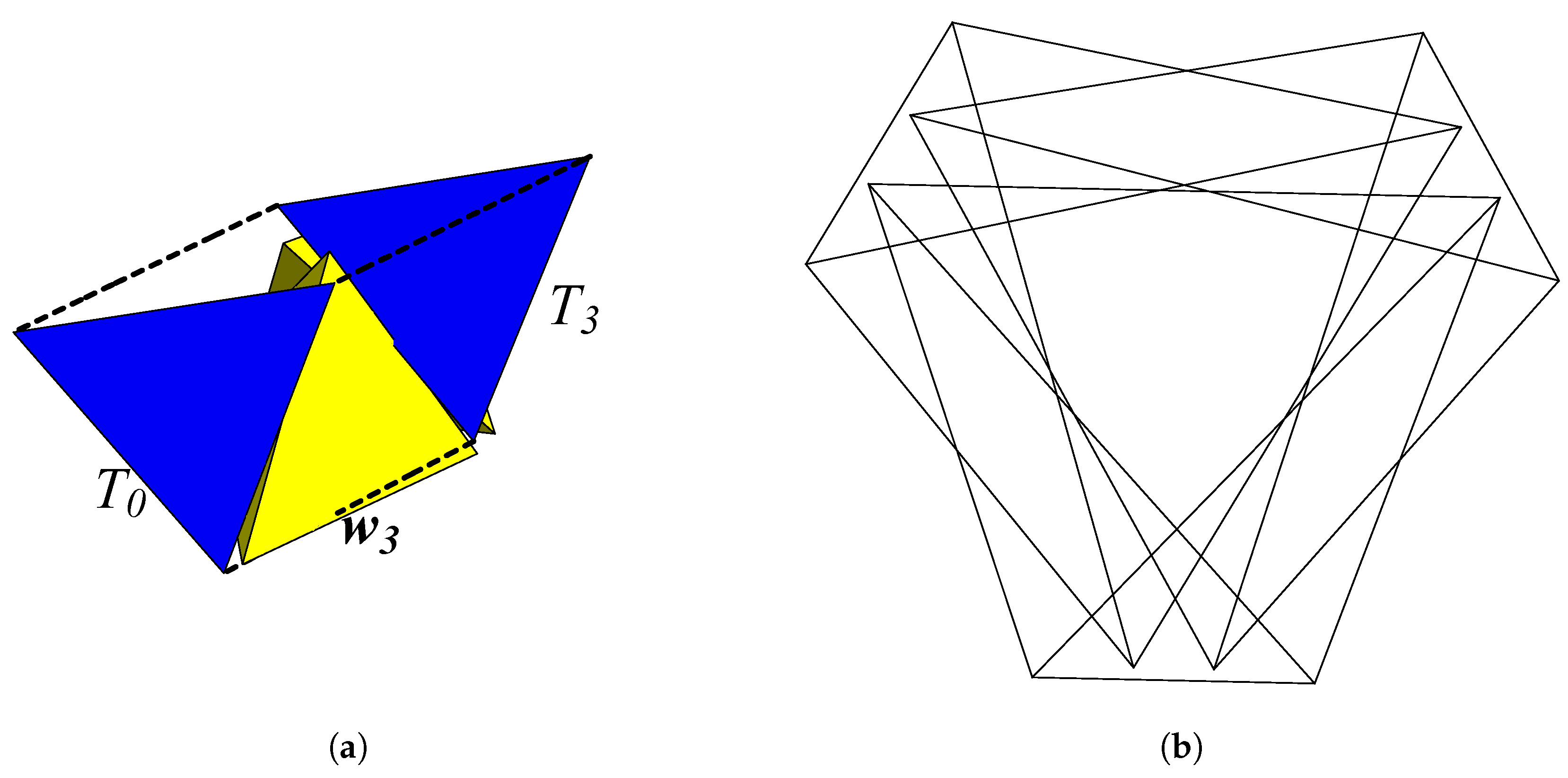
3.1. Standard BC Helix, Aperiodic

On the initial tetrahedron T 0 (Figure 3a), select as before a face f 0 (with unit normal n 0 ) where the next tetrahedron will be appended, and label the edges a 0 , b 0 , c 0 . Then, instead of reflecting through f 0 , rotate outward through it around a 0 by the tetrahedron’s dihedral angle. This yields the same appended tetrahedron T 1 as if we had reflected through f 0 , but it transforms f 0 to a new face f 1 (Figure 3b). The edges are likewise transformed to a 1 , b 1 , and c 1 with, of course, a 1 = a 0 , since that was the axis of rotation.
In subsequent steps, T k + 1 is generated by rotating T k through face f k around one of { a k , b k , c k } , where the a , b , and c are used cyclically. Thus, rotations are taken successively about a 0 , b 1 , c 2 , a 3 , b 4 , …. This sequence assures that f k is always the correct face across which to extend the BC helix, which will be left-/right-handed if { a 0 , b 0 , c 0 } are ordered clockwise/counterclockwise around f 0 .
Periodicity of the helix, or lack thereof, is determined by whether any tetrahedron T k has the same orientation as T 0 , up to the group symmetries of the tetrahedron. We can test for this most easily by ignoring the translations of the tetrahedra, locating all their centroids at the origin, and observing how they are rotated relative to T 0 .
To do so, let S k be a copy of T k = ( v k 0 , v k 1 , v k 2 , v k 3 ) with its centroid z k translated to the origin. That is,
S k = ( w k 0 , w k 1 , w k 2 , w k 3 ) , w k j v k j z k , z k 1 4 j v k j .
Let { a k , b k , c k } be unit vectors at the origin, parallel respectively to the edges { a k , b k , c k } of T k . The rotation about the edge a k by any angle can be represented as a sequence of, first, a translation taking one vertex of a k to the origin; next, a rotation about a k by the given angle; and finally, a translation taking the origin back to the vertex of a k . A corresponding sequence represents rotations about b k and c k . Ignoring translations, then, to compare the orientations of the T k , we look at the S k , each of which is determined simply by rotations about the vectors { a j , b j , c j } for j < k .
The geometric, or Clifford, algebra C 3 is particularly convenient for representing rotations in the Euclidean space E 3 [6,7,8], so this shall be the primary tool for our analysis. Rotation of the Euclidean vectors is a special case of the rotation of multivectors in C 3 , where a mulitvector M is rotated by a rotor R and its reverse R ˜ ,
R ˜ R = R R ˜ = 1 ,
M = R ˜ M R .
R itself is a multivector subject to such transformations. Moreover, a product of rotors is another rotor, along with its reverse,
( R 1 R 2 ) Z ˜ = R ˜ 2 R ˜ 1 .
We can write a rotor, among other ways, as a bivector exponential or as the product of two vectors. Let I be the right-handed unit trivector, and let v and w be arbitrary unit vectors separated by an angle θ . The rotor for a rotation by 2 θ in the v , w -plane is
R u , θ = e I u θ = v w , R ˜ u , θ = e I u θ = w v ,
with u another unit vector orthogonal to that plane and oriented so that { u , v , w } is a right-handed (though not orthogonal) triple. I u is the unit bivector of the v , w -plane.
We apply this now to S k . The important quantity, which shall be our focus throughout this section, is the rotor U k that determines S k . It is composed of a sequence of rotations about vectors a 0 , b 1 , c 2 , a 3 , , [ g ] ( k 1 ) , where [ g ] represents either a, b, or c, whichever is the kth term. The angle of rotation in each case is the tetrahedron’s dihedral angle, arccos 1 3 , so let δ be the dihedral half-angle. We can therefore express the rotations in rotor form as
S k = U ˜ k S 0 U k
U k e I a 0 δ e I b 1 δ e I c 2 δ e I a 3 δ e I [ g ] ( k 1 ) δ
δ = 1 2 arccos 1 3 = arccos 2 3 .
(This assumes a right-handed rotation about each [ g ] j , so the direction of each along its specified line must be correctly chosen; we shall do that shortly). Equation (11) is an intuitive form exhibiting explicitly how S 0 is rotated successively about the different axes, but all the distinct non-commuting bivectors in the exponents make this difficult to work with. Two simplifications will remedy this.
The first comes from the relationship between a k , b k , and c k , which are defined to lie parallel to the sides of the equilateral triangle face f k , normal to n k . As mentioned in the preceding paragraph, the line on which each lies has been specified, but not the direction along that line. For Equation (11) to be valid when used in Equation (10), choose { a k , b k , c k } to be cyclically oriented in a right-handed sense relative to n k (Figure 4), such that, e.g., b k is directed from edge a k to c k . Hence,
a k b k = b k c k = e I n k 2 π 3 .
Figure 4 confirms that a right-handed rotation about a k is the same orientation as the rotation about edge a k that takes the tetrahedron outward through face f k in the direction of n k , as required to correctly construct the BC helix.
Equation (13) can be solved for b k and c k in terms of a k as
b k = e I n k π 3 a k e I n k π 3 = e I n k k π 3 a k e I n k k π 3 for k = 1 mod 3
c k = e I n k 2 π 3 a k e I n k 2 π 3 = e I n k k π 3 a k e I n k k π 3 for k = 2 mod 3 .
Therefore, the sequence a 0 , b 1 , c 2 , … can be written g 0 , g 1 , g 2 ,… with
g k = e I n k k π 3 a k e I n k k π 3 .
With this first simplification we eliminate the bs and cs from U k in Equation (11). The price is the introduction of ns (in Equation (15)), but it allows us to write each factor in a uniform way, distinguished only by the value of its index, whence
U k = 0 k 1 e I g j δ .
The second simplification is to address the fact that in Equation (15), the a k and n k of each successive transformation are themselves the results of all the previous transformations, so that U k has a multitude of distinct bivector exponents. Fortunately, this can be reduced to a form in terms of only a 0 and n 0 . We begin by illustrating with an example, then prove the general lemma.
Consider three rotors R 1 , R 2 , and R 3 . For a general multivector M (including the R j ) define
M R ˜ 1 M R 1
M R ˜ 2 M R 2 = R ˜ 2 R ˜ 1 M R 1 R 2
M R ˜ 3 M R 3 = R ˜ 3 R ˜ 2 R ˜ 1 M R 1 R 2 R 3 .
As with the tetrahedra of our BC helix, each successive rotation of M is implemented by a rotor which is itself transformed by all the previous rotations. Now our focus is on the rotors themselves. The rotor that acts on M to produce M is
R 1 R 2 = R 1 ( R ˜ 1 R 2 R 1 ) = R 2 R 1 .
To produce M , the rotor is
R 1 R 2 R 3 = R 1 R 2 ( R ˜ 2 R ˜ 1 R 3 R 1 R 2 ) = R 3 R 1 R 2 = R 3 R 2 R 1 .
It becomes evident, then, that a sequence of rotations where each rotor is transformed by the previous ones can be expressed as a reordered sequence where each rotor is the original, untransformed rotor.
To prove the general case, begin with the following definitions. Let R 00 , , R n 0 represent a set of initial rotors, and define
R 0 R 00
R k 0 k 1 R j Z ˜ R k 0 0 k 1 R j for k { 1 , , n } .
This is just a generalization of Equation (17), though the notation here differs slightly from that example: rather than allow a proliferation of prime symbols, we use a naught subscript to denote an initial rotor, and its absence indicates a rotor transformed by all the rotors of lower index. Of course,
0 k 1 R j Z ˜ 0 k 1 R j = 0 k 1 R j 0 k 1 R j Z ˜ = 1 ,
since the product of rotors is a rotor. We now prove the lemma, that a sequence of successively transformed rotations is equivalent to the reverse sequence of untransformed rotations.
Lemma 1.
For rotors R k defined by Equation (20) up to any non-negative integer k,
0 k R j = k 0 R j 0 .
Proof. 
The proof is by induction. By Equation (20a) we know the lemma holds for k = 0 . For k > 0 , assume it holds for k 1 . Then
0 k R j = 1 k 1 R j R k = 0 k 1 R j 0 k 1 R j Z ˜ R k 0 0 k 1 R j = R k 0 0 k 1 R j = R k 0 k 1 0 R j 0 = k 0 R j 0 .
From here follows our first theorem, which presents the simple rotor form for any tetrahedron in the helix.
Theorem 1.
A rotor U k giving the orientation of tetrahedron T k (relative to T 0 ) in the Boerdijk–Coxeter helix can be expressed as the kth power of a constant rotor, this constant being a compound of rotations about a face normal and the direction of an edge. Namely,
U k = e I n 0 k π 3 e I n 0 π 3 e I a 0 δ k e I n 0 π 3 e I a 0 δ k ,
where ≅ here means equivalent up to a symmetry of the tetrahedron.
Proof. 
Begin with the definition in Equation (11) of U k , and use Equation (15) and Lemma 1.
U k = e I a 0 δ e I b 1 δ e I c 2 δ e I a 3 δ e I [ g ] ( k 1 ) δ = 0 k 1 e I n j j π 3 e I a j δ e I n j j π 3 = k 1 0 e I n 0 j π 3 e I a 0 δ e I n 0 j π 3 = e I n 0 ( k 1 ) π 3 k 1 1 e I a 0 δ e I n 0 j π 3 e I n 0 ( j 1 ) π 3 e I a 0 δ = e I n 0 k π 3 e I n 0 π 3 k 1 1 e I a 0 δ e I n 0 π 3 e I a 0 δ = e I n 0 k π 3 e I n 0 π 3 e I a 0 δ k .
The leading rotor in the last line is e I n 0 k π 3 ; when U k acts on S 0 , this is the one that acts first. It produces a 2 π 3 k rotation around n 0 , which leaves S 0 invariant.  □
The rotor product ( e I n 0 π 3 e I a 0 δ ) in U k is of course equivalent to a single rotation of some angle θ about some axis. The cosine of θ / 2 is given by the scalar part of the product, which has a simple form since the two exponents are perpendicular,
cos θ 2 = e I n 0 π 3 e I a 0 δ = cos π 3 cos δ = 1 6 .
This gives θ = arccos ( 2 / 3 ) , an irrational fraction of a circle, so U k will not return S 0 to itself for any non-zero integer k. It confirms the well-known fact that the BC helix is aperiodic. We now show, however, that modifying it with an extra twist around n k in each step can yield a periodic structure.

3.2. Modified BC Helix, Periodic

Theorem 2.
The BC helix can be modified to have period m for any integer m > 1 .
Proof. 
The proof is constructive. Follow the construction of the standard BC helix as above, but after each rotation about a k , b k , or c k , insert a rotation about n k by some fixed angle β . The resulting kth rotor U k m for the m-BC helix is found as in Equation (23),
U k m e I a 0 δ e I n 0 β 2 e I b 1 δ e I n 1 β 2 e I c 2 δ e I n 2 β 2 e I [ g ] ( k 1 ) δ e I n ( k 1 ) β 2 = 0 k 1 e I n j j π 3 e I a j δ e I n j j π 3 e I n j β 2 = k 1 0 e I n 0 j π 3 e I a 0 δ e I n 0 j π 3 + β 2 = e I n 0 ( k 1 ) π 3 k 1 1 e I a 0 δ e I n 0 j π 3 + β 2 e I n 0 ( j 1 ) π 3 e I a 0 δ e I n 0 β 2 = e I n 0 ( k 1 ) π 3 k 1 1 e I a 0 δ e I n 0 π 3 + β 2 e I a 0 δ e I n 0 π 3 + β 2 e I n 0 π 3 = e I n 0 ( k 1 ) π 3 e I a 0 δ e I n 0 π 3 + β 2 k e I n 0 π 3 .
To keep β paired with the δ rotation, the rearrangement in lines 4 and 5 above differs slightly from that done in Equation (23); this results in the extra e I n 0 π 3 on the end.
The modified BC helix generated by U k m is m-periodic if U m m 1 when acting on S 0 . The leading and trailing rotors in U k m are already symmetries of S 0 , so it remains to make the central factor one as well when k = m . This can be done by choosing β such that
e I a 0 δ e I n 0 π 3 + β 2 m = ± 1 .
For m = 0 this is trivial. Otherwise, for some unit vector h and any integer p,
e I a 0 δ e I n 0 π 3 + β 2 = ( ± 1 ) 1 m = e I h p π m e I a 0 δ e I n 0 π 3 + β 2 = e I h p π m cos δ cos π 3 + β 2 = cos p π m β = 2 arccos cos p π m cos δ 2 π 3 .
This has a solution when δ < p π m < π δ . Numerically, δ 0.98 π 5 , so we require 1 5 p m 4 5 (no new solutions appear if we take p > m ). Clearly no integer p satisfies this for m = 1 , but for any m > 1 there is some p that does (e.g., let p = m 2 ). Then U m m = ± e I n 0 k π 3 1 when acting on S 0 . □
Remark 1.
β is an angle of rotation around n k for each tetrahedron S k , but a 2 π 3 rotation around n k is a symmetry of S k , so the 2 π 3 can therefore be dropped,
β = 2 arccos cos p π m cos δ U m m 1 acting on S 0 .
This is the general formula for angles to modify a BC helix to have period m.
Remark 2.
While m is the number of tetrahedra in a period, p is the number of windings. That is, for p > 1 , the tetrahedra wind around repeatedly, but may not return to the original orientation until the pth winding, which occurs at the mth tetrahedron. If they do, m will not be the shortest period of that helix. In the interest of uniqueness, this motivates the following definition.
Definition 1.
An m-BC helix is a BC helix modified according to Theorem 2 so as to have period m, but no shorter period.
Corollary 1.
From Definition 1 and Theorem 2, an m-BC helix requires that the p m in cos p π m be irreducible, so
For integer m > 1 , m-BC helix p Z m 5 p 4 m 5 gcd ( m , p ) = 1 .
(The approximate inequality can be made exact by using the exact value of δ as shown in Theorem 2, which admits of slightly wider bounds.)
Theorem 3.
There is an m-BC helix for all integers m > 1 except 6.
Proof. 
For m { 2 , 3 , 4 , 5 } , both conditions in Corollary 1 are satisfied by p = 1 , so corresponding m-BC helices exist. Indeed, for m = 5 , one can choose p = 1 or 2, and get two distinct helices.
For m = 6 , the inequality in Corollary 1 is satisfied only by p { 2 , 3 , 4 } , none of which is coprime with 6, so there is no 6-BC helix (periodicity of 6 only occurs as a multiple of periodicities 2 or 3).
For 6 < m < 30 , a straightforward check reveals a satisfactory p for each m (usually more than one).
For m 30 , use a lemma of D. Hanson [9] that there is a prime between 3 n and 4 n for n > 1 . First define positive integers q, r, n by
m 6 q + r , r < 6
n m 6 = q + 1 .
Then
3 n = 3 q + 3 > m 2 ( since r < 6 ) ,
4 m 5 = 24 q + 4 r 5 = 4 q + 4 5 ( q + r ) 4 q + 4 = 4 n for q 5 .
These can be summarized as
m 2 < 3 n < 4 n 4 m 5 .
Since q 5 n > 1 , Hanson’s lemma applies, indicating a prime between 3 n and 4 n , hence between m 2 and 4 m 5 . This fits it within the bounds shown in Equation (29), slightly tighter than the exact bounds, so it satisfies the exact version of the Corollary 1 inequality. As a prime less than m but greater than half m, it is coprime with m, so it satisfies the coprime condition as well. We conclude that an m-BC helix exists for q 5 , i.e., for m 30 . □
From Equation (28) with p = 1 , we find for m = 3 and 5,
cos 1 2 β 3 = 3 8 cos β 3 = 1 4 cos β 3 2 π 3 = 1 + 3 5 8 = 3 ϕ 1 4 ,
cos 1 2 β 5 = 3 8 ϕ cos β 5 = 3 ϕ 1 4 .
In Equation (35) we used the congruency of a 2 π 3 rotation to shift the angle, and in Equation (36) we used cos ( π / 5 ) = ϕ / 2 and also ϕ 2 1 = ϕ . These values confirm β given in Equation (4).
It may be worth mentioning that the mathematics here describes abstract helix structures in which the modifying rotations do not generally avoid the intersecting of nearby tetrahedra. In a physical model with any nonzero β , the extra rotation will cause T k to crash into T k 2 and T k + 2 unless some extra translation is introduced to avoid it.

4. Modified BC Helices: Explicit Examples

In this section we will describe the assembly of the 3- and 5-BC helices. The approach used here generates a primitive set of tetrahedra following the method of assembly described in Section 2 while using the value of β in Equation (4). Modified BC helices of arbitrary length may then be generated by translating copies of this primitive set along the helix’s central axis (explicitly provided below). Due to the presence of the golden ratio in Equation (4), we refer to such a structure by the name “philix”.
In order to keep the expressions simple, we choose the starting tetrahedron in a convenient way. The expressions for any desired philix axis can be obtained by multiplying the values given here by the corresponding rotation matrix. At the conclusion of each of the sections below, the appropriate transformation is offered to align the philix axis with the z-axis of R 3 .
Interestingly, the sign of β will determine whether a 3- or a 5-period philix is generated according to the following rule:
(i) 
When the chiralities of the rotation by β and that of the underlying helix produced by the face sequence F = f 0 , f 1 , , f k arealike, one obtains a 5-period philix.
(ii) 
When the chiralities of the rotation by β and that of the underlying helix produced by the face sequence F = f 0 , f 1 , , f k areunlike, one obtains a 3-period philix.
In the constructions of Section 4.1 and Section 4.2, face sequences are used such that a right-handed underlying helix is produced. Accordingly, a positive value of β generates a 5-BC helix, while a negative value generates a 3-BC helix. For compactness, the values of the primitive tetrahedral vertices, central axis vector, and central helix radius and pitch are given in these sections. All values and expressions necessary to compute the transformations A T k f k and B T k f k are given in Appendix A.

4.1. The 5-BC Helix

Using T k = v k 0 , v k 1 , v k 2 , v k 3 , v k j R 3 , to designate a tetrahedron of an 5-BC helix, a primitive set for a 5-period philix may be formed from the unit-edge length tetrahedra { T 0 , , T 4 } given by
T 0 : v 00 = 0 , 0 , 2 3 1 2 6 v 01 = 1 2 3 , 1 2 , 1 2 6 v 02 = 1 2 3 , 1 2 , 1 2 6 v 03 = 1 3 , 0 , 1 2 6
T 1 : v 10 = 0 , 0 , 5 2 6 v 11 = 1 + 3 5 + 3 6 2 5 16 3 , 1 + 3 5 6 2 5 16 , 1 2 6 v 12 = 1 + 3 5 3 6 2 5 16 3 , 1 + 3 5 + 6 2 5 16 , 1 2 6 v 13 = 1 + 3 5 8 3 , 1 4 1 2 3 5 , 1 2 6
T 2 : v 20 = 1 12 3 , 4 + 5 12 , 8 + 3 5 6 6 v 21 = 11 + 3 5 24 3 , 5 + 5 24 , 8 + 3 5 6 6 v 22 = 5 3 5 12 3 , 5 + 5 12 , 5 6 6 v 23 = 5 72 3 + 3 15 , 5 24 1 + 5 , 11 6 6
T 3 : v 30 = 5 4 5 12 3 , 5 12 , 11 + 2 5 6 6 v 31 = 13 11 5 24 3 , 3 + 7 5 24 , 8 + 5 5 6 6 v 32 = 13 5 5 24 3 , 3 + 7 5 24 , 8 + 5 5 6 6 v 33 = 5 + 2 5 6 3 , 5 6 , 5 + 2 5 6 6
T 4 : v 40 = 5 1 5 12 3 , 5 + 5 12 , 5 + 4 5 6 6 v 41 = 5 + 5 24 3 , 5 1 + 5 24 , 11 + 4 5 6 6 v 42 = 11 + 13 5 24 3 , 5 5 24 , 8 + 7 5 6 6 v 43 = 1 + 8 5 12 3 , 4 + 5 12 , 8 + 5 6 6 .
A 5-period philix may be generated by translating the vertices of these tetrahedra by integer values of a vector w 5 R 3 given by
w 5 = 5 3 + 15 36 , 5 + 5 12 , 5 + 2 5 3 6 ,
such that
v j + 5 k i = v j i + k w 5 , for k Z .
When this is done, one obtains a structure with five-fold rotational symmetry (in its projection) and a linear “period” of 5 tetrahedra along its central axis. (See Figure 5 for this 5-period philix, and Figure 6 for comparison with the 3-period version. See also Mathematica Notebook S1 in the Supplementary Materials at the end of the article for 3D rotatable images.) The centroids of the tetrahedra comprising a 5-period philix form a helix with a linear pitch of
p 5 = 25 18 + 5 5 9
and a radius of
r 5 = 5 5 15 2
producing a helix with the parameterization c : R R 3 given by:
c t = r 5 u 1 cos t + u 2 sin t + t 4 π w 5 + q 5 ,
where u 1 = 1 6 , 1 2 , 1 3 and u 2 = 1 2 1 3 5 + 5 , 1 2 1 + 1 5 , 1 15 + 6 5 are orthonormal vectors spanning the plane perpendicular to the philix axis w 5 , and
q 5 = 5 5 30 3 , 1 30 5 5 , 5 5 15 6
>is a vector to translate the helix to the location of the philix above (as its axis does not pass through the origin). The tetrahedral centroids lie on this helix at the positions given by t = k 4 π 5 , k Z .
The 5-period philix described in this section may by aligned with the z-axis by applying the transformation
H 5 v = C 5 v q 5 ,
to each vertex v k j of the philix, where
C 5 = 1 24 9 75 + 30 5 1 4 1 2 10 + 5 + 75 + 30 5 3 + 5 5 + 5 6 5 + 2 5 300 + 132 5 1 4 1 2 10 + 5 + 75 + 30 5 5 8 1 8 3 + 6 5 1 2 1 1 5 25 123 + 55 5 2 6 5 + 2 5 7 / 2 1 2 1 1 5 5 360 + 161 5 3 5 + 2 5 7 / 2
is a matrix that rotates w 5 to the direction of 0 , 0 , 1 .

4.2. The 3-BC Helix

The 3-period philix (Figure 1c) is produced here using an approach similar to that of the 5-period philix in Section 4.1. Here, a primitive set { T 0 , T 1 , T 2 } is taken such that T 0 is as before (see Equation (37) on page 10) and
T 1 : v 10 = 0 , 0 , 5 2 6 v 11 = 1 + 3 5 3 6 2 5 16 3 , 1 + 3 5 + 6 2 5 16 , 1 2 6 v 12 = 1 + 3 5 + 3 6 2 5 16 3 , 1 + 3 5 6 2 5 16 , 1 2 6 v 13 = 1 + 3 5 8 3 , 1 4 1 2 3 5 , 1 2 6
T 2 : v 20 = 1 12 3 , 4 5 12 , 8 + 3 5 6 6 v 21 = 5 3 5 12 3 , 5 + 5 12 , 5 6 6 v 22 = 11 + 3 5 24 3 , 5 + 5 24 , 8 + 3 5 6 6 v 23 = 5 3 + 3 15 72 , 5 1 5 24 , 11 6 6 .
To generate the tetrahedra of the 3-period philix, one translates these primitive tetrahedra along an axial direction (as in Section 4.1), which now has the value
w 3 = 5 + 3 5 12 3 , 5 5 12 , 5 3 6 .
In other words, the 3-period philix is produced using the tetrahedra { T 0 , T 1 , T 2 } above such that
v j + 3 k i = v j i + k w 3 , for k Z .
The structure one one obtains has three-fold rotational symmetry (in its projection) and a linear “period” of 3 tetrahedra along its central axis (see Figure 6). As with its 5-period sibling, the tetrahedral centroids of the 3-period philix form a helix. The corresponding values for the pitch ( p 3 ) and radius ( r 3 ) are substantially simpler than in the 5-period case, and are given by
p 3 = 5 6
r 3 = 2 9
The corresponding parameterization to Equation (46) is
c t = r 3 u 1 cos t + u 2 sin t + t 2 π w 3 + q 3 ,
u 1 is as before, u 2 = 1 12 2 3 10 , 1 + 5 2 6 , 1 3 , and q 3 = 1 9 3 , 1 9 , 1 9 2 3 . In this case, tetrahedral centroids lie on the helix at t = k 2 π 3 , k Z .
To align the philix of this section with the z-axis, one may use the analog of Equation (48), with
C 3 = 1 12 3 4 5 1 12 2 3 + 15 1 12 3 2 + 10 1 12 2 3 + 15 3 4 2 + 10 4 3 1 12 3 2 10 1 12 6 + 30 5 3 .

5. Conclusions

It is known that the BC helix exhibits an aperiodic nature such that it possesses no non-trivial translational or rotational symmetries. Here we have developed modified varieties of this structure, producing helices of tetrahedra possessing both translational and rotational (in their projections) symmetries along/about their central axes. Unique cases of such a structure with period m have been designated in this writing as m-BC helices, and we have shown how to construct these for any m > 1 but six, with an explanation of why a six-period helix cannot be unique. We also presented detailed construction of two particular variations: the 3-BC helix (3-period philix) and the 5-BC helix (5-period philix). The construction process of the m-BC helices resembles that of the standard BC helix, however a rotation is added after each new tetrahedron is appended to the chain. When the value of β given by Equation (4) is used, the relative chiralities of this rotation and the underlying chain of tetrahedra determines whether a 3- or 5-period philix is produced.

Supplementary Materials

Mathematica Nobebook S1: m-BC-helix-ancillary.nb, 3D rotatable images of the 3- and 5-period philices. This file can be viewed with the Wolfram Player, available for free at https://www.wolfram.com/player/.

Author Contributions

Conceptualization, F.F. and K.I.; Investigation, F.F., G.S. and R.C.; Methodology and Writing Manuscript, G.S. and R.C.; Software, G.S. and F.F.; Supervision, K.I.

Funding

This research received no external funding.

Conflicts of Interest

The authors declare no conflict of interest.

Appendix A. The Transformations A T k f k and B T k f k

The transformations A T k f k and B T k f k of Section 2 have the form
A T f v = M T f v c T f + c T f
B T f v = R T f v c T f + c T f ,
where M T f O ( 3 ) is a reflection matrix through a mirror parallel to face f of tetrahedron T, R T f SO ( 3 ) is a rotation matrix by β through an axis normal to the face f, and c T f is the center of the tetrahedral face f on T. The values of M T k f k , R T k f k , T k , and c T k f k necessary to generate the primitive tetrahedra in Section 4.1 and Section 4.2 are given here.

Appendix A.1. Transformations Related to the 5-BC Helix

The reflection matrices M T 0 f 0 , , M T 3 f 3 are as follows:
M T 0 f 0 = 1 0 0 0 1 0 0 0 1
M T 1 f 1 = 1 18 5 3 5 1 6 18 14 5 3 1 9 23 + 3 5 1 6 18 14 5 3 1 6 3 + 5 1 3 1 5 3 1 9 23 + 3 5 1 3 1 5 3 7 9
M T 2 f 2 = 1 18 11 + 3 5 1 + 5 6 3 1 9 5 2 3 + 5 1 + 5 6 3 1 6 3 5 5 + 5 3 6 1 9 5 2 3 + 5 5 + 5 3 6 1 9
M T 3 f 3 = 1 18 11 3 5 1 + 5 6 3 1 9 5 2 3 + 5 1 + 5 6 3 1 6 3 + 5 5 + 5 3 6 1 9 5 2 3 + 5 5 + 5 3 6 1 9 .
The rotation matrices R T 0 f 0 , , R T 3 f 3 are given by:
R T 0 f 0 = 1 8 1 + 3 5 1 4 3 2 3 5 0 1 4 3 2 3 5 1 8 1 + 3 5 0 0 0 1
R T 1 f 1 = 1 72 38 + 15 5 1 24 287 380 5 3 1 9 2 1 24 83 104 5 3 1 2 + 5 5 24 1 6 14 16 5 3 23 + 9 5 36 2 5 + 5 12 6 1 9 2 + 3 5
R T 2 f 2 = 1 144 65 + 33 5 19 + 5 48 3 29 9 5 36 2 41 + 11 5 48 3 1 48 9 + 17 5 1 + 5 12 6 11 9 5 36 2 1 6 369 + 165 5 1 18 11 + 3 5
R T 3 f 3 = 5 36 + 3 5 8 13 2 5 24 3 8 + 3 5 18 2 17 + 4 5 24 3 1 2 + 5 5 24 7 2 5 6 6 1 36 83 33 5 11 7 5 12 6 1 18 11 + 3 5 .
The face centers c T 0 f 0 , , c T 3 f 3 are:
c T 0 f 0 = 0 , 0 , 1 2 6
c T 1 f 1 = 1 + 3 5 24 3 , 1 12 1 2 3 5 , 7 6 6
c T 2 f 2 = 1 72 3 7 15 , 1 24 3 5 1 , 8 + 5 6 6
c T 3 f 3 = 1 72 3 9 15 , 1 24 1 + 3 5 , 8 + 3 5 6 6 .
The intermediate tetrahedra T 0 , , T 3 are given by:
T 0 : v 00 = 0 , 0 , 2 3 1 2 6 v 01 = 1 2 3 , 1 2 , 1 2 6 v 02 = 1 2 3 , 1 2 , 1 2 6 v 03 = 1 3 , 0 , 1 2 6
T 1 : v 10 = 0 , 0 , 5 2 6 v 11 = 1 3 5 8 3 , 1 8 1 5 , 1 2 6 v 12 = 1 4 3 , 5 4 , 1 2 6 v 13 = 5 72 3 + 3 15 , 5 24 5 1 , 11 6 6
T 2 : v 20 = 1 12 3 , 1 12 5 4 , 8 + 3 5 6 6 v 21 = 13 11 5 24 3 , 1 24 3 + 7 5 , 8 + 5 5 6 6 v 22 = 5 3 5 12 3 , 1 12 5 + 5 , 5 6 6 v 23 = 5 72 3 + 3 15 , 5 24 5 1 , 11 6 6
T 3 : v 30 = 5 4 5 12 3 , 5 12 , 11 + 2 5 6 6 v 31 = 13 11 5 24 3 , 1 24 3 + 7 5 , 8 + 5 5 6 6 v 32 = 11 + 13 5 24 3 , 1 24 5 5 , 8 + 7 5 6 6 v 33 = 5 + 2 5 6 3 , 5 6 , 5 + 2 5 6 6 .

Appendix A.2. Transformations Related to the 3-BC Helix

The reflection matrices M T 0 f 0 and M T 1 f 1 are as follows:
M T 0 f 0 = 1 0 0 0 1 0 0 0 1
M T 1 f 1 = 1 18 5 3 5 7 + 5 6 3 1 9 23 + 3 5 7 + 5 6 3 1 6 3 + 5 1 3 1 5 3 1 9 23 + 3 5 1 3 1 5 3 7 9 .
The rotation matrices R T 0 f 0 and R T 1 f 1 are given by:
R T 0 f 0 = 1 8 1 + 3 5 1 4 3 2 3 5 0 1 4 3 2 3 5 1 8 1 + 3 5 0 0 0 1
R T 1 f 1 = 1 72 38 + 15 5 1 24 287 380 5 3 1 9 2 1 24 83 104 5 3 1 2 + 5 5 24 1 6 14 16 5 3 23 + 9 5 36 2 1 12 5 3 3 + 5 1 9 2 + 3 5 .
The face centers c T 0 f 0 and c T 1 f 1 are:
c T 0 f 0 = 0 , 0 , 1 2 6
c T 1 f 1 = 1 + 3 5 24 3 , 1 12 1 2 3 5 , 7 6 6 .
The intermediate tetrahedra T 0 and T 1 are given by:
T 0 : v 00 = 0 , 0 , 2 3 1 2 6 v 01 = 1 2 3 , 1 2 , 1 2 6 v 02 = 1 2 3 , 1 2 , 1 2 6 v 03 = 1 3 , 0 , 1 2 6
T 1 : v 10 = 0 , 0 , 5 2 6 v 11 = 1 4 3 , 5 4 , 1 2 6 v 12 = 1 3 5 8 3 , 1 8 1 + 5 , 1 2 6 v 13 = 5 72 3 + 3 15 , 5 24 5 1 , 11 6 6 .

References

  1. Coxeter, H.S.M. Regular Complex Polytopes; Cambridge University: Cambridge, UK, 1974. [Google Scholar]
  2. Boerdijk, A.H. Some remarks concerning close-packing of equal spheres. Philips Res. Rep. 1952, 7, 30. [Google Scholar]
  3. Gray, R.W. Tetrahelix Data. Available online: http://www.rwgrayprojects.com/rbfnotes/helix/helix01.html (accessed on 4 January 2013).
  4. Fang, F.; Irwin, K.; Kovacs, J.; Sadler, G. Cabinet of curiosities: The interesting geometry of the angle β = arccos((3ϕ − 1)/4). arXiv 2013, arXiv:1304.1771. [Google Scholar]
  5. Fuller, B.R. Synergetics: Explorations in the Geometry of Thinking; Macmillan: London, UK, 1975. [Google Scholar]
  6. Suter, J. Geometric Algebra Primer. Available online: https://www.semanticscholar.org/paper/Geometric-Algebra-Primer-Suter/53cb5062e533706aeadfbd62a2d43fbe3754a007 (accessed on 8 October 2019).
  7. Lounesto, P. Clifford Algebras and Spinors; Cambridge University Press: Cambridge, UK, 2001. [Google Scholar]
  8. Hestenes, D. New Foundations for Classical Mechanics; Springer: Berlin, Germany, 2012. [Google Scholar]
  9. Hanson, D. On a Theorem of Sylvester and Schur. Can. Math. Bull. 1973, 16, 2. [Google Scholar] [CrossRef]
Figure 1. Canonical and modified Boerdijk–Coxeter helices: (a) a right-handed Boerdijk-Coxeter (BC) helix; (b) a “5-BC helix” may be obtained by appending and rotating tetrahedra through the angle given by Equation (4) using the same chirality of the underlying helix; (c) a “3-BC helix” may be obtained by appending and rotating tetrahedra through the angle given by Equation (4) using the opposite chirality of the underlying helix.
Mathematics 07 01001 g001
Figure 2. Assembly of modified BC helix: (a) a segment of an m-BC helix with face f identified on tetrahedron T k ; (b) an interim tetrahedron, T k (shown in blue), is appended (face-to-face) to f on T k ; (c) finally, T k + 1 is obtained by rotating T k through the angle β about the axis n k .
Mathematics 07 01001 g002
Figure 3. First step in constructing the standard BC helix: (a) the initial tetrahedron T 0 , with face f 0 , edges { a 0 , b 0 , c 0 }, and normal n 0 ; (b) T 0 with T 1 and the transformed face, edges, and face normal.
Mathematics 07 01001 g003
Figure 4. S k , the kth rotation of S 0 = T 0 . n k is the face normal, and unit vectors { a k . b k , c k } are aligned with edges { a k , b k , c k } .
Mathematics 07 01001 g004
Figure 5. The periodicity of the 5-BC helix: (a) the vertices of T 5 are the vertices of T 0 translated by w 5 ; (b) a projection of the 5-BC helix along its central axis.
Mathematics 07 01001 g005
Figure 6. The periodicity of the 3-BC helix: (a) the vertices of T 3 are the vertices of T 0 translated by w 3 ; (b) a projection of the 3-BC helix along its central axis.
Mathematics 07 01001 g006

