1. Introduction
During the last few decades, an increasing number of modern spacecraft with various space missions, such as earth observation as well as rendezvous and docking, have been released into space as a result of the significant advancements of science and technology in space research. In order for spacecraft to successfully accomplish their missions, an attitude control system with high control performance is of paramount importance. Therefore, the problem of attitude control design has become one of the most important and broadly studied topics, and numerous control strategies have been employed to develop attitude controls for spacecraft, approaches such as sliding mode control [
1], back-stepping control [
2], passivity-based control [
3], adaptive control [
4], fuzzy control [
5], neural networks control [
6], and observer-based control [
7], just to mention a few. Although these control results provide satisfactory performance, they are based on the assumption that full-state measurements are available to construct the controller. From a practical point of view, rotation velocity sensors such as gyroscopes are expensive and sensitive to noise. Furthermore, the rotation velocity measurement can become unavailable due to unexpected malfunctions or catastrophic failure in gyro sensors [
8,
9]. Thus, it is of critical theoretical and practical importance to design output feedback control such that the angular velocity measurement is not required [
10].
By virtue of a linear filter, a saturated output feedback for a rigid spacecraft attitude system has been presented in [
11] such that there is no need to measure the spacecraft angular velocity. Based on a first-order filter and a coordinate transformation, the authors in [
12] proposed a neural-network-based adaptive attitude control for rigid bodies subject to system uncertainty and attitude measurement only. Using extended-state observer and adaptive dynamic programming, the problem of spacecraft attitude control with unavailable angular velocity measurement has been studied in [
13]. A novel output feedback control algorithm for spacecraft close-range proximity maneuvers subject to space disturbance torque, forbidden zone, and actuator saturation has been reported in [
14]. To deal with the unavailability of angular velocity measurements, a proportional-integral observer-based model with predictive attitude control for uncertain rigid spacecraft has been presented in [
15]. Ref. [
16] proposed a sum of square-based nonlinear
output feedback attitude control strategies for uncertain flexible spacecraft in the presence of disturbance, parameter uncertainty, and actuator saturation. However, the convergence rate is exponential at best, meaning that the system states converge to zero within an infinite time horizon.
To make the system trajectories converge to zero within a finite time, Ref. [
17] designed a finite-time extended-state observer-based output feedback control for attitude maneuvering and the disturbance rejection of a rigid spacecraft in the presence of the actuator fault. A saturated neural-network-based adaptive output feedback attitude control with finite-time convergence has been developed in [
18]. The unknown angular velocity is first estimated by a neural-state observer, and a command-filtered back-stepping control is then designed, such that the computation complexity problem is effectively resolved. Despite the fact the existing finite-time output feedback controls are effective and steer the system states to the origin within a finite time, the convergence time is a function of the spacecraft’s initial states, and it can be unboundedly increased. To deal with this problem, based on the concept of fixed-time sliding mode control, the problem of distributed output feedback attitude consensus control for multiple rigid spacecraft has been studied in [
19], such that the requirement of an angular velocity measurement is removed, and the system trajectories converge to zero during a finite time that is independent of initial attitude. Although the upper bound of the settling time only depends on control parameters, it is difficult to determine a specific convergence time since at least four parameters contribute to estimating the settling time [
20,
21,
22,
23].
According to the aforementioned discussion, this paper studies the problem of output feedback attitude control with predefined-time convergence for uncertain rigid spacecraft. To design the controller, the attitude system with attitude measurement only is converted to a new system with strict feedback form by a mapping. The states of the converted system are fully available for controller formulation. However, the converted system is encountered with unmatched uncertainty due to the mapping. Then, an adaptive smooth predefined-time back-stepping control for the converted system is designed. In contrast to fixed-time output feedback controls, the settling time under the proposed control framework is determined as a tunable gain. Moreover, it is proved that the controller is free of singularity resulting from the fractional power used for predefined-time convergence. Moreover, we develop an anti-windup compensator in a predefined-time design framework in order to overcome the input saturation effect.
3. Adaptive Predefined-Time Attitude Control
In this section, an anti-windup adaptive back-stepping control with predefined-time convergence is developed to stabilize the converted system (
20). Thus, the following error variables, associated with a back-stepping framework, are defined
where
,
, and
denote the virtual control, such that
.
Step 1: The dynamics of
along the first subsystem of (
20) can be calculated as
To stabilize the error
, motivated by [
24,
29], the following nonsingular predefined-time virtual control is introduced
where
where
,
,
, and
.
Let us construct a positive-definite Lyapunov function as
. Differentiating
along Equation (
23), substituting the virtual control (
24) and employing Lemma 6, one has
Since
and using
, then
. Based on Lemma 5 we have
Step 2: For the second subsystem of (
20), we have
. Then, one obtains
where
is the lumped uncertainty, such that
, where
is a positive but unknown constant.
Remark 4. Due to the fact , to prove the boundedness of δ, we just need to show that both ζ and are bounded. The boundedness of ζ has been analyzed in Remark 1. Moreover, the denominator of the virtual control in Equation (
24)
is always positive and nonzero; thus, it is well defined. Its time derivative is also bounded. To be more exact, its time derivative is obtained as follows:whereandandwhere and . If we had employed the conventional back-stepping control procedure, the virtual control would be , and its time derivative (as can be seen in Equation (
32))
might give rise to a singularity problem when and for . However, the time derivative of the virtual control (
24)
contains the term , and thus we have , where , , and . So, the singularity problem is directly resolved [24,29]. Therefore, it is reasonable to assume that is upper bounded. To guarantee the predefined-time convergence of
in the presence of the lumped uncertainty
, motivated by [
24,
29], the following adaptive virtual control is used.
where
,
and
The parameter
is updated by the following adaptive law
where
,
and
.
Now, we define an augmented Lyapunov function as
, where
,
and
. Differentiating
along (
28) and importing (
33), one obtains
In light of the Young’s inequality, we have
By virtue of Lemma 2, and by defining
,
,
,
, and
, one obtains
According to the update law (
35) and using Lemma 3, it can be concluded that
, and then
. Therefore, by virtue of Lemma 4 and defining
and
, we have
Substituting (
39) and (
38) into (
36) results in
where
.
Step 3: Similar to the previous steps, differentiating
along the
-subsystem, one can obtain
where
is the lumped uncertainty, such that
, where
is a positive but unknown constant. To guarantee the predefined-time convergence of
in the presence of the lumped uncertainty
and the input saturation, the following adaptive anti-windup control input is designed
where
,
and the parameter
is updated by the following adaptive law
where
,
and
. Moreover, the anti-windup compensator is described by
where
.
Theorem 1. Consider the uncertain rigid spacecraft attitude system (
8)
with unmeasured angular velocity. In light of the converted system (
20)
and Assumptions 1–3, applying the virtual attitude controls (
24)–(
33)
, the actual attitude control (
42)
and the updates laws (
35), (
43),
and (
44)
guarantees that the equilibrium of the attitude system is practical predefined-time stable and the attitude variable is driven to the following region Proof. Construct the final Lyapunov function as
, where
,
,
, and
. Differentiating
V along (
41) and importing the control input (
42), one obtains
where
. According to Lemma 1, the equilibrium of the system (
20) is practical predefined-time stable, and the attitude variable
is driven to the following region [
24]
This completes the proof. □
Remark 5. The block diagram of the output feedback control framework proposed for the rigid spacecraft attitude system has been illustrated in Figure 1. 4. Simulation Results
In this section, we present the results of Monte Carlo-type simulations and a comparison with two different attitude controls for a rigid spacecraft. A rigid spacecraft with inertia matrix
is considered [
26]. It is assumed that the external disturbances acting upon the spacecraft are
The limitations of the actuator torques are considered as
and
for
. The parameters of the proposed control scheme are taken as
,
,
,
,
,
,
,
,
, and
. The section is divided into two parts.
Part 1: The effectiveness of a control system depends on its ability to maintain the desired output under varying operating conditions. One way to evaluate the performance of the control system is to conduct simulations with different initial conditions and analyze the resulting behavior. In the first part of the simulation results section, we conduct Monte Carlo-type simulations with 100 different initial conditions to evaluate the variability and sensitivity of the attitude system to different starting points. Monte Carlo-type simulations are used to study the behavior of the system under random input conditions, which makes them particularly useful in analyzing the performance of the control system. The Monte Carlo simulation results are provided in
Figure 2,
Figure 3,
Figure 4,
Figure 5 and
Figure 6.
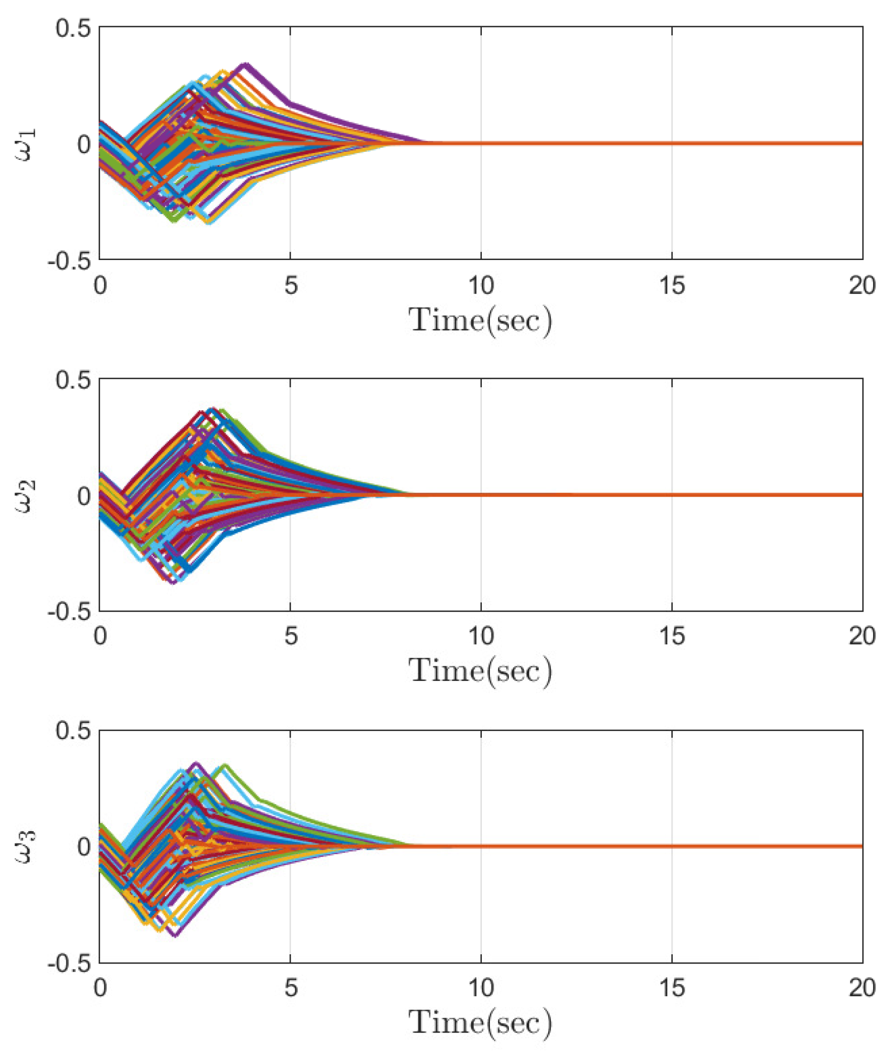
Figure 2 and
Figure 3 show that the quaternion and angular velocity of the attitude system are stabilized before the convergence time
. The convergence of the quaternion and angular velocity is an important indicator of the stability and performance of the control system. The steady-state behaviours of the attitude quaternion and angular velocity are illustrated in
Figure 4 and
Figure 5. As expected, these variables converge to a small region around the origin within a predefined time and stay thereafter. The Monte Carlo simulations demonstrate that the control approach is robust and effective in ensuring that the system responds appropriately to different initial conditions. Moreover, as is observed in
Figure 6, the anti-windup compensator guarantees that the required control torque is always less than the maximum limit. Therefore, these findings highlight the effectiveness and efficiency of the proposed control approach in stabilizing the system and reducing its response time without placing excessive demands on the actuator. These results provide valuable insights into the performance of the control system under different operating conditions.
Part 2: The second part of the simulation results section compares the performance of the proposed control approach with that of two other control approaches: an output feedback back-stepping attitude control (OFBAC) [
30] and a neural-network-based adaptive output feedback attitude control (NNBOFAC) [
12]. The OFBAC approach uses a back-stepping technique to recursively control the orientation of the rigid spacecraft. To implement the OFBAC control law, an extended-state observer is used to estimate the angular velocity and external disturbances acting on the spacecraft. The estimated values are then utilized in the OFBAC control law to determine the appropriate control actions. Additionally, the NNBOFAC is a neural-network-based control method that leads to an exponential convergence of the closed-loop system and does not require the direct measurement of angular velocity. Its use of a neural network allows for flexible and adaptive control, and its ability to achieve exponential convergence and estimate the angular velocity without direct measurement makes it a powerful and robust control approach. These control approaches are appropriate candidates to challenge the proposed control scheme in terms of robustness and performance given their different underlying principles and design features. It should be noted that these two approaches do not take into account the actuator saturation, and their gains are selected so that the required control torque does not exceed its maximum limit. On the other hand, the proposed control approach is designed to explicitly account for actuator saturation, resulting in faster settling time and better overall performance.
The initial conditions are selected as
and
rad/s. The simulation results are provided in
Figure 7,
Figure 8 and
Figure 9.
Figure 7 illustrates the time response of the spacecraft attitude in terms of quaternion. As is observed, the proposed control scheme results in a faster convergence rate as the quaternion variables require less time to converge to their equilibrium points.
Figure 8 shows the angular velocity under the proposed control scheme is stabilized with a faster rate, such that the angular velocity stabilization is provided before
; while the angular velocity under OFBAC and NNBOFAC is stabilized after about 10 and 12 s, respectively. Despite the fact that the proposed control framework shows superior control performance, the time response of the control input depicted in
Figure 9 reveals that all the three approaches do not violate constraints on the control input, and the maximum control torque is not bigger that its limit, i.e., 3 Nm. Therefore, the efficacy and advantage of the suggested control strategy is confirmed.
5. Conclusions
In this paper, a saturated model-free output feedback control for a rigid spacecraft attitude maneuver is presented. Since the angular velocity of the spacecraft is assumed to be unavailable, a first-order filter is employed to convert the attitude system into a system with the full state available. Nevertheless, the converted system contains unmatched uncertainty. Then, a back-stepping control with predefined-time convergence is developed. It is guaranteed that all the states of the converted system are predefined-time stable, and the convergence time is easily specified by a single parameter in the final controller. Therefore, the origin of the original attitude system is predefined-time stable, even when the angular velocity measurement is not available. Additionally, a nonlinear predefined-time anti-windup is proposed to resolve the problem of input saturation. The simulation results confirm the effectiveness and efficacy of the novel output feedback control strategy.
As a future work, we will modify the first-order filter to a prescribed-time-stable filter to guarantee the prescribed-time convergence of the closed-loop system in the presence of the filter. Moreover, we will employ a prescribed performance control to specify the desired performance in transient and steady states, such as the convergence region that the system states are driven to.


