Article

Multi-Agent Deep Q-Network Based Dynamic Controller Placement for Node Variable Software-Defined Mobile Edge-Cloud Computing Networks

1
College of Computer Science and Electronic Engineering, Hunan University, Changsha 410082, China
2
School of Computer Science and Engineering, Central South University, Changsha 410083, China
*
Author to whom correspondence should be addressed.
Mathematics 2023, 11(5), 1247; https://doi.org/10.3390/math11051247
Submission received: 26 January 2023 / Revised: 22 February 2023 / Accepted: 2 March 2023 / Published: 4 March 2023
(This article belongs to the Topic Complex Systems and Network Science)

Abstract

:
Software-defined networks (SDN) can use the control plane to manage heterogeneous devices efficiently, improve network resource utilization, and optimize Mobile Edge-Cloud Computing Networks (MECCN) network performance through decisions based on global information. However, network traffic in MECCNs can change over time and affect the performance of the SDN control plane. Moreover, the MECCN network may need to temporarily add network access points when the network load is excessive, and it is difficult for the control plane to form effective management of temporary nodes. This paper investigates the dynamic controller placement problem (CPP) in SDN-enabled Mobile Edge-Cloud Computing Networks (SD-MECCN) to enable the control plane to continuously and efficiently serve the network under changing network load and network access points. We consider the deployment of a two-layer structure with a control plane and construct the CPP based on this control plane. Subsequently, we solve this problem based on multi-agent DQN (MADQN), in which multiple agents cooperate to solve CPP and adjust the number of controllers according to the network load. The experimental results show that the proposed dynamic controller deployment algorithm based on MADQN for node-variable networks in this paper can achieve better performance in terms of delay, load difference, and control reliability than the Louvain-based algorithm, single-agent DQN-based algorithm, and MADQN- (without node-variable networks consideration) based algorithm.

1. Introduction

With the development of mobile internet, mobile devices with limited hardware performance cannot meet the demand of mobile applications for device performance [1]. Cloud computing can leverage abundant computing and storage resources for mobile devices. However, the problem is that cloud computing centers and mobile devices have high propagation latency, which makes it impossible to provide ultra-low latency services. Mobile Edge Computing (MEC) can serve devices at the edge of the network close to the mobile device, thus meeting the ultra-low latency needs of mobile applications. The resources of edge servers are limited, so overloading is possible. The cloud-edge collaboration system combines the advantages of cloud computing and edge computing. On-demand scheduling of cloud or edge computing resources to serve mobile devices can provide sufficient computing resources while meeting the ultra-low latency requirements of mobile applications [2].
However, there is a large number of heterogeneous movable devices in MECCN. MECCN cannot fully utilize the network resources to provide QoS for huge amounts of data [3]. The SDN can use the control plane to achieve flexible and efficient management of devices and make network-wide decisions to improve network resource utilization and optimize network performance [4].
The control plane makes all network decisions in SD-MECCN. Therefore, it is important to deploy a high-performance and highly reliable control plane for SD-MECCN. Constrained by the performance bottleneck of a single controller, distributed multi-controller control plane should be deployed in massive networks. Moreover, dynamic deployment of the control plane in mobile networks is necessary to adapt to network changes [5]. However, MECCN is a large-scale network with wide coverage, and the network topology is constantly changing. The flat control plane in the MECCN will face high synchronization overhead due to the frequently synchronized state information between controllers. In the hierarchical control plane, there is no need to synchronize state information between controllers of the same layer, which can reduce the state synchronization overhead [6].
To improve the performance of the control plane in a wide area network (WAN), Hou et al. [7] proposed a two-layer control plane to ensure load balancing and high reliability while reducing latency. Maity et al. [8] proposed a hierarchical dynamic control plane deployment strategy that allows the control plane to adjust its performance as the network traffic changes dynamically. However, most of the existing dynamic deployment algorithms are based on heuristic algorithms, which have poor real-time performance and cannot adapt to the real-time requirements of control plane adjustment due to rapid changes in network state.
Deep Reinforcement Learning (DRL) can be used to learn and build network knowledge using neural networks for fast decision-making [9]. Li et al. [10] proposed a three-layer control plane dynamic deployment strategy based on multi-agent deep reinforcement learning, which can adjust the control plane performance with the change of network state in time.
However, hotspot areas in the MECCN may sometimes have insufficient network capacity, thus requiring additional temporary network access points and access to new switches to meet user requirements. However, the existing controller deployment strategy can rarely cope with the scenario where the number of switches changes.

1.1. Motivation

The network access points need to be added temporarily when network resources in the hotspot areas are insufficient, and these new access points must also be managed by the controllers. However, none of the existing controller deployment strategies considers the impact of the temporary access points on the network and cannot adjust the deployment scheme of the controller according to the temporary access points. Therefore, the neglection of temporary access points will affect the ability of the control plane to regulate the network, thereby affecting the quality of network service, especially the quality of network service provided by the temporary access point. Table 1 compares the differences between this paper and some important papers.

1.2. Contribution

In this paper, we study the dynamic deployment strategy of the hierarchical control plane in the variable number of switches scenario to reduce the state synchronization overhead between controllers. Moreover, MECCN has high requirements for latency and reliability, and we construct a controller deployment model that considers latency, load balancing, and control reliability. Finally, we solve the problem based on multi-agent deep reinforcement learning to ensure real-time control plane adjustment. The specific contributions are as follows.
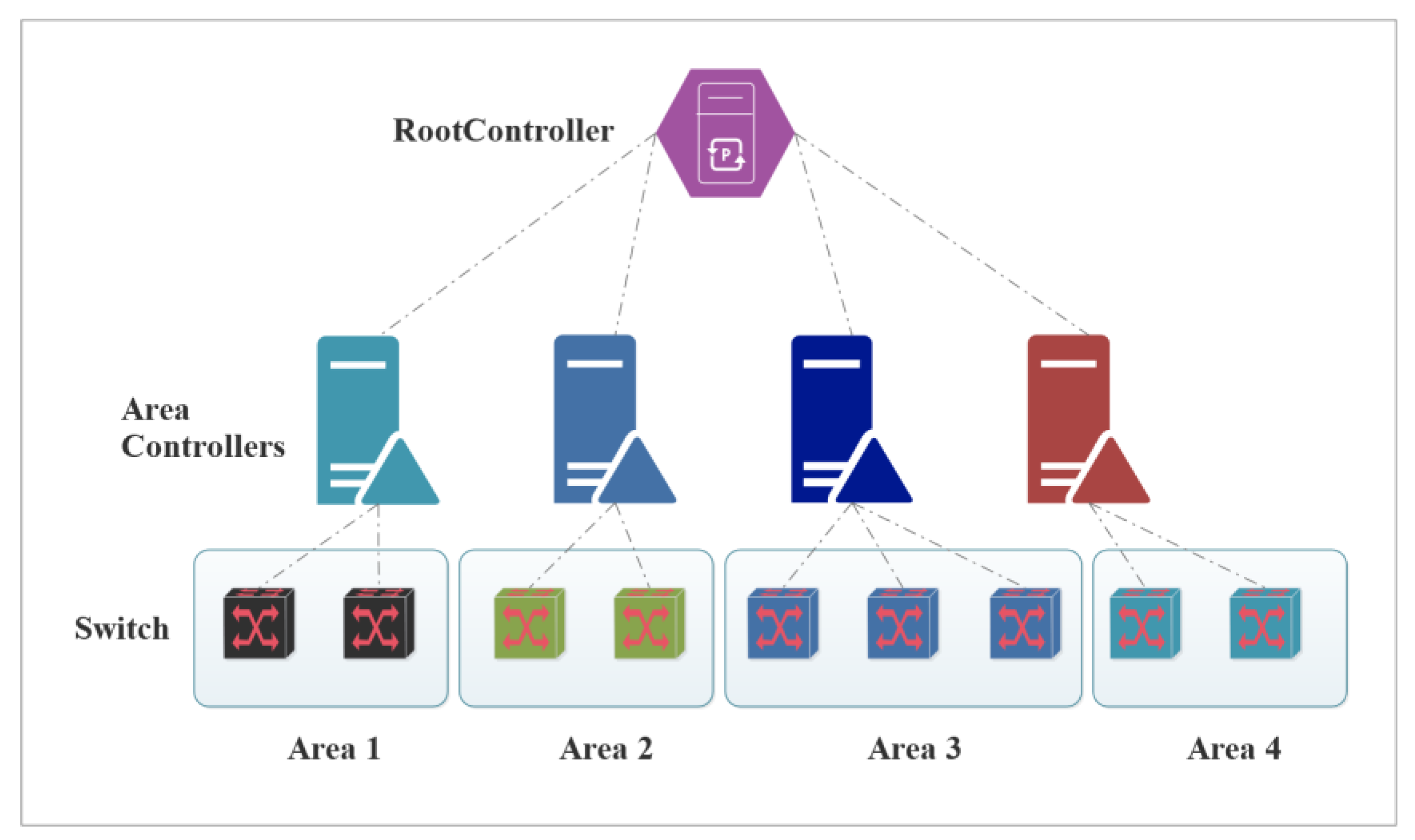
  • We study a two-layer control plane containing area controllers and root controllers. We construct demand-aware latency, loading difference, and control reliability models to deploy the control plane.
  • We design a dynamic controller deployment algorithm based on multi-agent deep reinforcement learning to solve the controller deployment problem in networks with a variable number of switches.
  • We dynamically adjust the number of controllers according to the controller load to solve the problem of scattered choices among agents in a multi-agent body system.
  • The numerical results show that the CRADCPH-MADQN (Controller Requirement Aware Dynamic Controller Placement for Hierarchical Architecture based on Multi-agent Deep Q-network) algorithm outperforms the other three baselines, including Louvain-based algorithm [7], single-agent DQN-based algorithm [11], and MADQN- [10] (without node-variable networks consideration) based algorithm in terms of delay, load balance, and reliability.
The remainder of the paper is organized as follows. In Section 2, we present the relevant research work. In Section 3, we describe the system model and problem formulation. In Section 4, we present the dynamic controller placement algorithm for SD-MECCN. Section 5 presents simulation results, and Section 6 concludes the paper.

2. Related Work

Heller et al. [12] proposed to solve CPP in SDN first. This approach finds the appropriate number and location of controller deployments in the network with the goal of latency minimization. In a wide area network (WAN), the long distances between network nodes lead to high data interaction latency between network devices. To address this problem, T. Zhang et al. [13] studied the impact of controller-to-controller and controller-to-switch interaction traffic on the controller deployment problem. Controller deployment needs to satisfy latency constraints and controller deployment costs. To address this issue, Han et al. [14] proposed to maximize the number of devices that can be managed by the controller, thereby achieving guaranteed latency requirements and reduced deployment costs. In WAN, the latency between controllers and switches is not only the propagation latency but also the end-to-end latency and the queuing latency of controllers. Therefore, Wang et al. [15] investigated the overall latency between controllers and switches. It reduces the queuing latency of a single controller by using a multi-controller deployment strategy. It also used a clustering algorithm to partition the network so as to reduce the end-to-end latency between controllers and switches. Liyanage et al. [16] proposed a hierarchical distributed controller deployment strategy for vehicular networking. The latency induced by the system is reduced by deploying the controllers in Road Side Units (RSUs). The above study proposes a deployment strategy based on latency. However, the load of different controllers in a large-scale network can vary greatly, affecting controllers’ response speed to network requests.
Since there are load differences between controllers, while changes in network traffic lead to changes in controller load, many research works consider both latency and load balancing. Hu et al. [17] proposed a controller deployment strategy. This policy minimizes controllers’ average or worst latency with guaranteed load balancing. In vehicular networking, uneven distribution of network nodes generates load imbalance problems. In vehicular networking, uneven distribution of network nodes generates load imbalance problems. Kaur et al. [18] proposed a heuristic approach based on the incremental expansion of candidate space to achieve energy minimization and load balancing under latency constraints. G. Schütz et al. [19] proposed a comprehensive mathematical formalization and a heuristic approach. The method is used to find the minimum number of controller deployments and the optimal deployment location. Thus, load balancing is achieved in the case of satisfying the latency constraint. The above research results consider both latency and load so that the control plane can satisfy the latency constraint and load balancing among different controllers. However, the above schemes cannot adapt to the dynamic changes of the network because the controller deployment scheme cannot be adjusted in real time as the network state changes.

3. System Model

In this section, we first introduce the two-layer architecture control plane for SD-MECCN. Then the latency, load difference, and control reliability models for deploying the control plane are constructed based on the two-tier structure control plane.
Figure 1 shows the two-layer structured control plane of SD-MECCN. The control plane consists of area controllers in the first layer and a unique root controller in the second. The first layer contains multiple area controllers that handle network requests directly from the switch. Different area controllers in the same layer are only responsible for maintaining the network structure information in their area and do not need to synchronize the state with other area controllers. The root controller is responsible for managing the network topology, thus ensuring the logical centralization of the control plane. The important notations are summarized in Table 2.

3.1. Network Model

This paper constructs SD-MECCN as a node-variable undirected graph G = (V; E). Where V is the set of nodes with different numbers at different moments and the maximum number is N. V = { v 1 , v 2 , , v N } , v i denotes switch i. E is the set of edges between nodes, and the number of elements varies with the number of V. The number of area controllers is X in the network. The set of area controllers can be expressed as A = { a 1 , a 2 , , a X } . The network has a unique root controller and is denoted as Y.

3.2. Delay Model

SD-MECCN is a heterogeneous distributed network with a wide coverage area and a large amount of data to be transmitted. Therefore, propagation delay, transmission delay, queueing delay, and processing delay need to be considered when modeling the delay of the network.
The delay between node a and node b is defined as:
d a , b = ( d a , r 1 p p + d a , r 1 t + d r 1 q + d r 1 p c ) + i = 1 n 1 ( d r i , r i + 1 p p + d r i , r i + 1 t + d r i q + d r i p c ) + ( d r n , b p p + d r n , b t + d r n q + d r n p c )
where r 1 to r n is the switch that data transmission between node a and node b needs to pass through, d a , r 1 p p is the propagation delay between node a and node r 1 , d a , r 1 t is the transmission delay between node a and node r 1 , d r 1 q is the queuing time of data in switch r 1 , and d r 1 p c is the processing time of data in the switch r 1 .
The propagation delay between node a and node r 1 is expressed as:
d a , r 1 p p = l a , r 1 v a , r 1
where l a , r 1 is the distance between node a and node r 1 ,   v a , r 1 is the signal propagation rate of node a and node r 1 .
The transmission delay between node a and node r 1 is expressed as:
d a , r 1 t = { d a , r 1 t w l , n o d e   a   a n d   n o d e   r 1   a r e   w i r e l e s s l y   c o n n e c t e d d a , r 1 t w d , n o d e   a   a n d   n o d e   r 1   a r e   w i r e d   c o n n e c t i o n s
When node a and node r 1 are connected wirelessly, interference between the two nodes needs to be considered. Considering the interference between different mobile devices [20], the transmission rate between mobile device a and switch r 1 is defined as follows:
B a , r 1 w = B o log 2 ( 1 + p a g a , r 1 N B o + a U p a g a , r 1 )
where B o is the bandwidth, N is the power spectral density of additive white Gaussian noise, g a , r 1 is the wireless channel gain between a and r 1 , p a is the sending power of mobile device a, U is the set of all mobile devices that interfere with mobile device a.
Therefore, the transmission delay of mobile devices communicating with the switch r 1 can be expressed as:
d a , r 1 t w l = D a B a , r 1 w
D a is the size of data to be sent by mobile device a.
When node a and r 1 use wired connection, the transmission delay between the two nodes can be expressed as:
d a , r 1 t w d = D a , r 1 B a , r 1
D a , r 1 is the size of the data sent by a and r 1 , B a , r 1 is the bandwidth of the link between a and r 1 .
When a massive amount of data need to be transmitted by a switch, the data need to be queued in the switch. We use the M/M/N model to model this process. Therefore, the sum of queueing and processing delay of data can be solved using the M/M/N model [10].
d r 1 q + d r 1 p c = f ( c r 1 , b r 1 , n , u r 1 , ρ )
c r 1 , b r 1 denotes the number of threads and cache of switch r 1 , n is the amount of data processed by the switch, u r 1 is the processing capacity of each thread, and ρ is the ratio of the average arrival rate of data to the average service rate.

3.3. Load Difference Model

In a distributed multi-controller control plane, the controller load varies due to the uneven distribution of network load [21]. Since controllers have different computing resources, the number of network requests that can be processed per unit of time also varies. Therefore, using the number of network requests does not accurately reflect the load of controllers. To measure controller load accurately, we use the ratio of the number of network requests to the maximum number of network requests that can be processed per unit of time as the controller load. Therefore, a load of the area controller a x is defined as:
l a x = r a x r m a x a x
r a x is the number of network requests being processed by the area controller a x , r m a x a x is the maximum number of network requests that the controller a x can process per unit of time.
The coefficient of variation is used to measure the degree of variation of sample data with different mean values. Since the mean values of the area controller loads in the control plane may be varied at different moments, we use the coefficient of dispersion of the different area controller loads to measure the load differences. Thus, the load difference of the area controller is defined as:
c v = σ μ
σ is the standard deviation of the different area controller’s load, μ is the mean of the different area controller’s load.

3.4. Control Reliability Model

The controller needs to be deployed in a location with high control reliability to ensure the continuity of control plane functions. The data transfer between the controller and the managed devices is done through the data plane. Therefore, whether the control information from the controller can reach the managed devices in time is related to the accessibility of the network path. The reliability of the communication between nodes is related to the links and intermediate nodes’ reliability [7,22]. In addition, when multiple paths between two nodes satisfy the delay constraint, data can be delivered through the remaining paths when one path fails.
We take the mean value of the control reliability of a controller a and all devices managed as the control reliability C a c of controller a and define it as:
C a c = i = 1 | V a | C a , i | V a |
where V a is the set of network devices controlled by controller a.
The control reliability C a , i between the controller a to the managed device i is related to the communication reliability within the delay constraint between them. C a , i is defined as:
C a , i = j = 1 g C a , i j
where g is the number of paths between a and i that satisfy the delay constraint, and C a , i j is the communication reliability of path j between controller a and device i.
The path between controller a and device i may have multiple intermediate nodes, so a path consists of multiple sublinks. Assuming that the number of path j with sublinks is n, the link reliability of sublink k is p k p on the path, the number of nodes on the path is m, and the reliability of node q is p q n , The communication reliability C a , i r of a path r that connects controller a to network device i can be defined as:
C a , i r = k = 1 n ( p k p ) q = 1 m ( p q n )
When the load among the links is higher, the possibility of control information arriving over time is higher. We define the physical failure probability of a link as p k b . Therefore, the link reliability p k p in the path is defined as:
p k p = ( 1 p k b ) s i g m o i d ( B k f k t )
where f k t is the network traffic of the kth link, B k is the bandwidth of the kth link.

3.5. Problem Formulation

We need to deploy a two-layer structure control plane in SD-MECCN. First, we deploy the first layer of area controllers to meet the ultra-low latency requirements of the application. Then, we find the appropriate location of the root controller according to the deployment scheme of area controllers to ensure the logical centralization of the SDN control plane.
In a network, the latency of all controllers to the managed devices needs to satisfy the latency constraint. Therefore, it is necessary to ensure that the maximum delay of the controllers to the managed devices is less than the constraint. In addition, to fully utilize the controller resources, the load difference of controllers should not be too large. Moreover, the control reliability of the controllers needs to be large enough to ensure the sustainability of the control plane function.
Therefore, latency, load difference, and control reliability constraints need to be satisfied when deploying area controllers. Since the three metrics have different scales, we use the Z-score algorithm to normalize the three metrics. Thus, the optimization problem of deploying area controllers can be expressed as follows:
min α 1 f ( D m a x a ) + β 1 f ( Δ l ) γ 1 f ( C a )
s t .   α 1 + β 1 + γ 1 = 1
D m a x a d m a x a ,   a V
Δ l l a m a x
C i c c 1 ,   i A
Line (14a) denotes that the sum of the weights of the three metrics is 1, (14b) denotes that the maximum delay from the mobile device to the controller in the switch controlled by the area controller cannot exceed d m a x a , (14c) denotes that the loading difference of different area controllers cannot be greater than l a m a x , (14d) denotes that the control reliability of any one area controller cannot be less than c 1 , L m a x a is the maximum value of the average delay from the controller to the controlled mobile devices among all area controllers, C a is the mean value of control reliability of all area controllers, f(x) is the Z-score normalization function [23].
Since only one root controller is available in the network, it is no longer necessary to focus on load balancing but only to ensure that the maximum latency of area controllers to the root controller meets the constraints and has high reliability. Therefore, the root controller optimization problem can be expressed as follows:
min α 2 f ( D m a x Y ) γ 2 f ( C Y )
s t .   α 2 + γ 2 = 1
D m a x Y d m a x r
C Y c 2
where (15a) denotes that the weighted sum is 1, (15b) denotes that the maximum delay from all area controllers to the root controller cannot exceed d m a x r , (15c) denotes that the control reliability of the root controller cannot be less than c 2 .

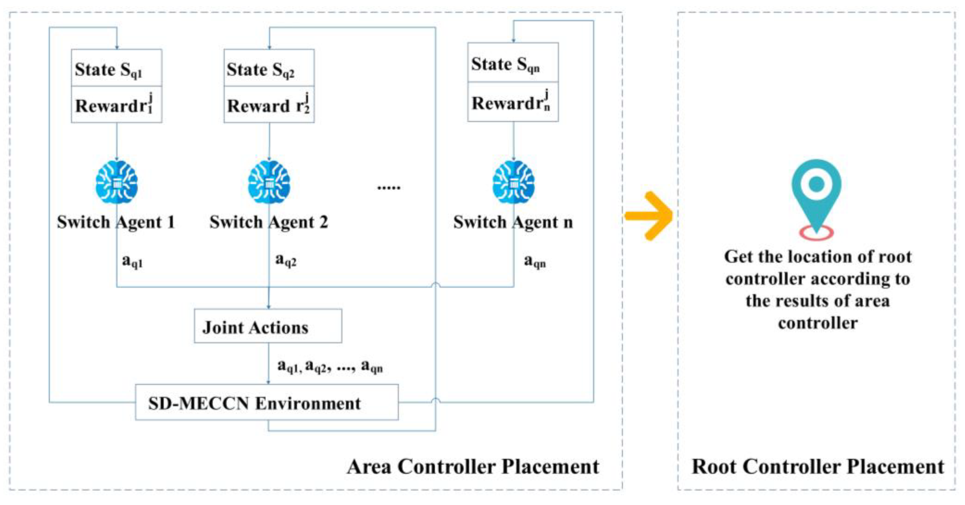
4. Dynamic Controller Placement for SD-MECCN

The SD-MECCN has many mobile nodes, so the network topology and load constantly change. Area controllers are responsible for handling network requests from the switches. The control plane needs to adjust the deployment schemes of area controllers according to network status to meet the network’s changing requirements. Then, it is necessary to find the appropriate location of the root controller according to the deployment scheme of the area controller. The proposed solution is shown in Figure 2.
The multi-controller deployment problem is a multi-objective combinatorial optimization problem (MOCO) and is NP-hard. Compared to heuristic algorithms, reinforcement learning (RL) can better solve the MOCO problem [24]. However, as the network scale keeps increasing, solving CPP using RL faces the dimensional explosion problem [10]. A deep Q-learning network (DQN) uses neural networks to compute Q values, thus solving the dimensional explosion problem to some extent. However, DQN [25] can only output one action with the highest Q value at a time, and when solving multi-dimensional action problems, the solution space is too large. Therefore, we use multi-agent DQN to solve this problem. To make the proposed algorithm in this paper adaptable to the network topology with a variable number of switches, we construct each switch as an agent. We dynamically use different agent output deployment schemes according to the change in the number of switches. We give the corresponding states, actions, and rewards in the following.
5.
State space:
The state needs to reflect changes in network state and controller performance so that the agent can select the correct action based on the state, so we define the state space corresponding to the agent of the switch v i as follows:
S v i = { d v i , a j ,   c v , C a j c , l a j , h v i , a j , r v i , n a l l , n t e m , a 1 , , a N }
where a j is the area controller corresponding to the switch j, h v i , a j is the shortest path hop count between the switch and the controller, r v i is the number of network requests generated by the switch, n a l l is the total number of switches in the network at that moment, and n t e m is the number of temporary switches in the network.
6.
Action space:
In the algorithm proposed in this paper, we use the agent to choose the group where each switch is located. Then, we choose the controller location within the group according to the optimization objective (14). Thus, the action space used to deploy the area controller is represented as:
A 1 = { ξ g v 1 } ,   g v i [ 0 , n 1 ]
where g v i denotes the area to which switch i belongs, and ξ is scale factor. Since the action’s output from the multi-agent DQN is scattered, we scale the actions according to the overall network load, thus reducing the number of controllers.
7.
Reward:
To better optimize the target, we design the reward based on Equation (14), which sets constraints on latency, loading difference, and reliability. To make the solution found by the agent satisfy these constraints, we add a penalty factor based on these constraints to the reward.
In summary, we define reward as:
r 1 = ( α 1 f ( L m a x a ) + β 1 f ( Δ l ) γ 1 f ( C a ) ) + i = 1 N p i
where p i denotes the value of the penalty factor calculated based on the state of switch i and the area controller to which switch i belongs.
Based on the multi-agent DQN algorithm, we design and implement the area controller placement algorithm after we have modeled each agent’s state, action, and reward. The specific algorithm is shown in Algorithm 1.
Algorithm 1. The MADQN-based area controller placement
Input: Requests from different switches SR, number of mobile devices UD, node-variable network topology G, current number of switches CS; weight factors a,b,c
Output: the solution of area controller placement
1. Initialize the multi-agent DQN environment envmadqn with topology G, SR, UD and a,b,c;
2. Initialize the initial actions of all agents preactions by the Louvain community detection algorithm;
3. for ep = 0; ep < maxep do
4. Initialize the initially state prestates of all agents according to preaction
5. for es = 0; es < maxstep do
6.   for i = 0; i < CS do
7.    Get the next action nextactions[i] of agent i according to prestates[i] by DQN;
8.   end for
9.  Get the next state nextstates, and the reward rews[i] according to nextactions;
10.  for i = 0; i < CS do
11.    Training the model in DQN of agents i according to prestate[i],nextstates[i],nextactions[i] and rews[i];
12.  end for
13.  prestates = nextstates;
14. end for
15. end for
16. Obtain the solution of area controller placement according to the actions with the maximum sum of rewards.
Finally, according to the deployment scheme of the area controller and the optimization objective (15), we choose the location with the largest optimization objective (15) value in the network as the location of the root controller. Since the solution space of the root controller is small, we do not use DRL for solving it anymore. The specific algorithm for solving the root controller is shown in Algorithm 2.
Algorithm 2. The root controller placement
Input: Requests from different switches SR, number of mobile devices UD, node-variable network topology G, weight factors a,c, the actions areaactions of area controller placement agents, the number of area controllers NA; current number of switches CS;
Output: the location of root controller RN
1. Initialize the algorithm with topology G, SR, UD, a, c and areaactions;
2. Get the delay from area controllers to the root controller yc by Equation (1);
3. Get the control reliability from area controllers to the root controller yc by Equation (10)
4. for i = 0; i < CS do
5. Get the reward of switches i;
6. end for
7. the node with the maximum reward is the location of the root controller.

5. Performance Evaluation

5.1. Simulation Setting

This section evaluates the proposed CRADCPH-MADQN algorithm under an IRIS Networks real-world topology obtained in Tennessee, USA [26]. The IRIS Networks include 51 nodes and 64 edges. The distance between nodes is calculated using the Haversine formula [27], and the shortest path between nodes is obtained using Dijkstra’s algorithm [28]. Our experimental scenario is a single-city scenario, and the topology used is obtained from multiple cities. Therefore, we use 1/10 of the distance in the topology as the experimental distance to calculate the propagation delay. Simulation parameters are given in Table 3.
Different areas of the city have different numbers of mobile devices. Hot spots have many mobile devices and high network traffic, while idle areas have few mobile devices and low network traffic. When the network traffic is excessive in certain regions, additional network access points are needed temporarily to meet the network demand of users. Therefore, we set the network nodes as busy nodes and non-busy nodes and design a different number of network requests, network load, and some mobile devices according to the characteristics of different regions at different times. We also design different temporary network access points according to the city’s foot traffic trend. Moreover, as the network load fluctuates, we add different numbers of mobile switches to expand the network capacity temporarily. The specific parameter generation regularity is shown in Table 4 and Table 5. The number of busy nodes is 20, and the number of non-busy nodes is 31. In generating the data, we first generate the number of mobile devices and the number of network requests for different nodes simultaneously using the normal distribution. After obtaining a mean value, we then use a Poisson distribution to produce the specific number of mobile devices and the number of network requests for each node. To verify the algorithm’s effectiveness, we generate a dataset for training and another for validation using the same data pattern.
In this section, we compare the proposed algorithm with the community partitioning algorithm [7] (named Louvain), the DQN-based algorithm (named DQN) [11], and the multi-agent DQN algorithm (named MADQN) [10] without considering variable nodes to verify the performance of the proposed algorithm.
Louvain [7]: Firstly, the Louvain community partition algorithm is used to partition the switch nodes, and then the appropriate node is selected as the area controller of a partition according to Equation (14) in each partition. We implemented a version of the algorithm that considers node variability.
DQN [11]: The single-agent DQN is used to partition the switch nodes in every step, and then the appropriate node is selected as the area controller of a partition according to Equation (14) in each partition. The algorithm does not consider node variability.
MADQN [10]: Multiple agents cooperate to complete the partition of switch nodes in every step, and then the appropriate node is selected as the area controller of a partition according to Equation (14) in each partition. The algorithm does not consider node variability.

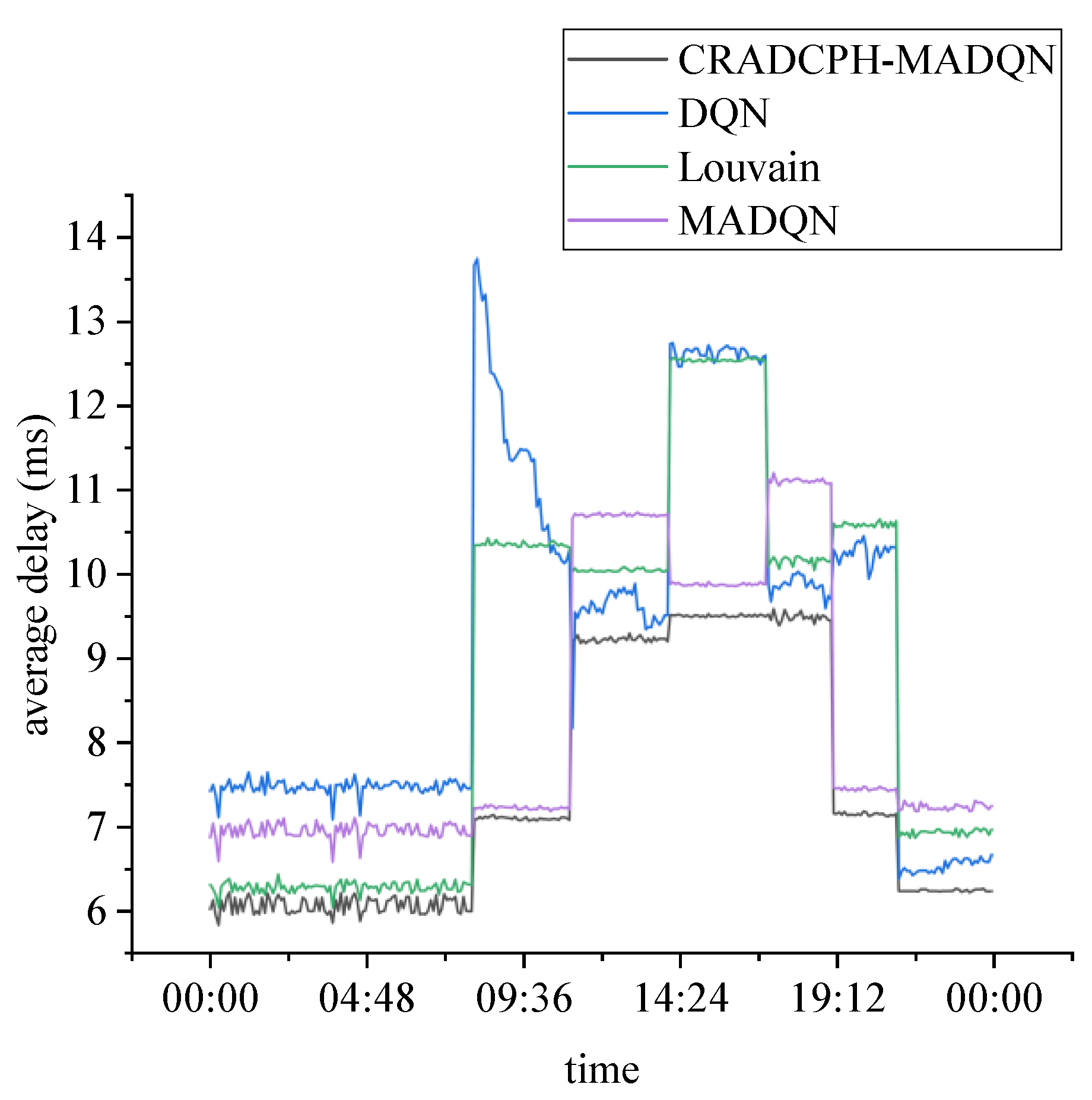
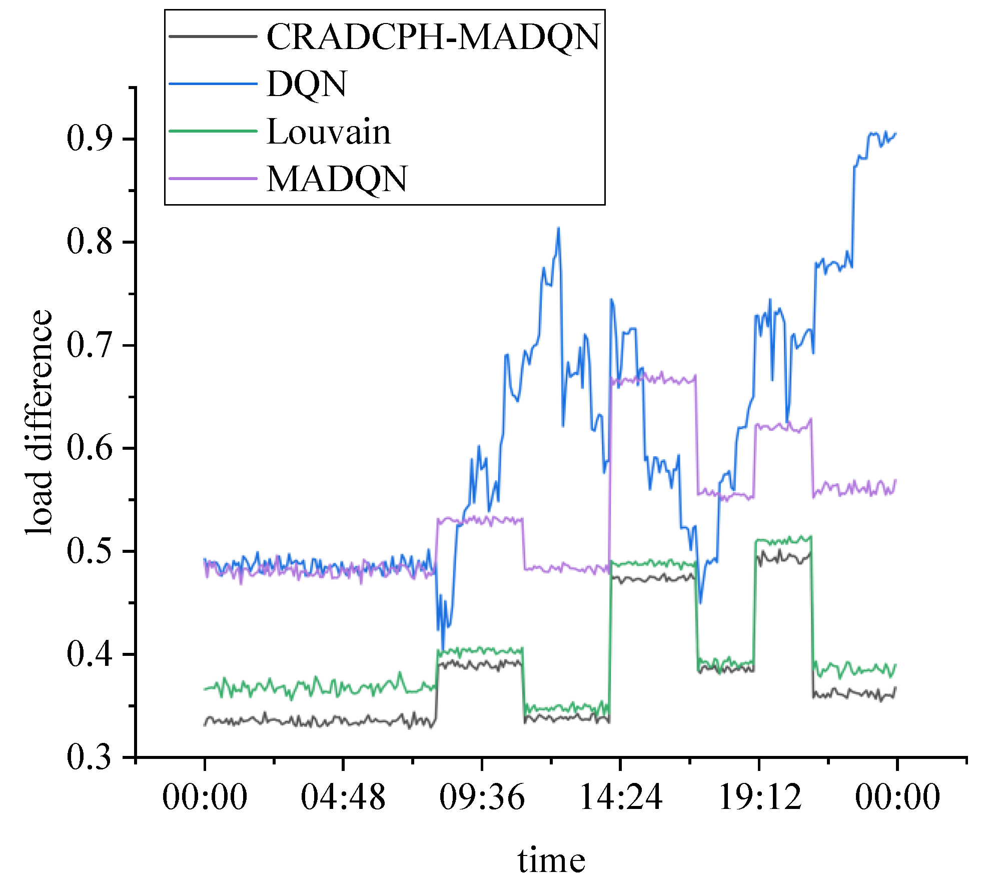
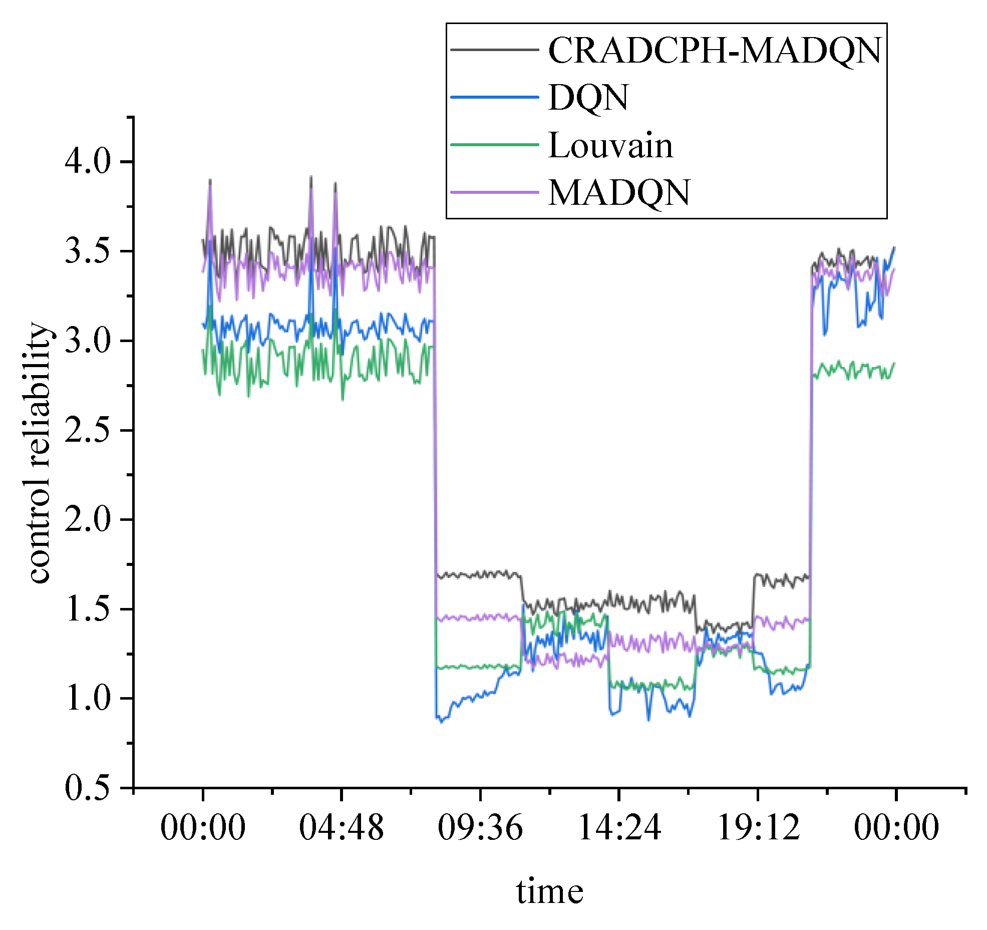
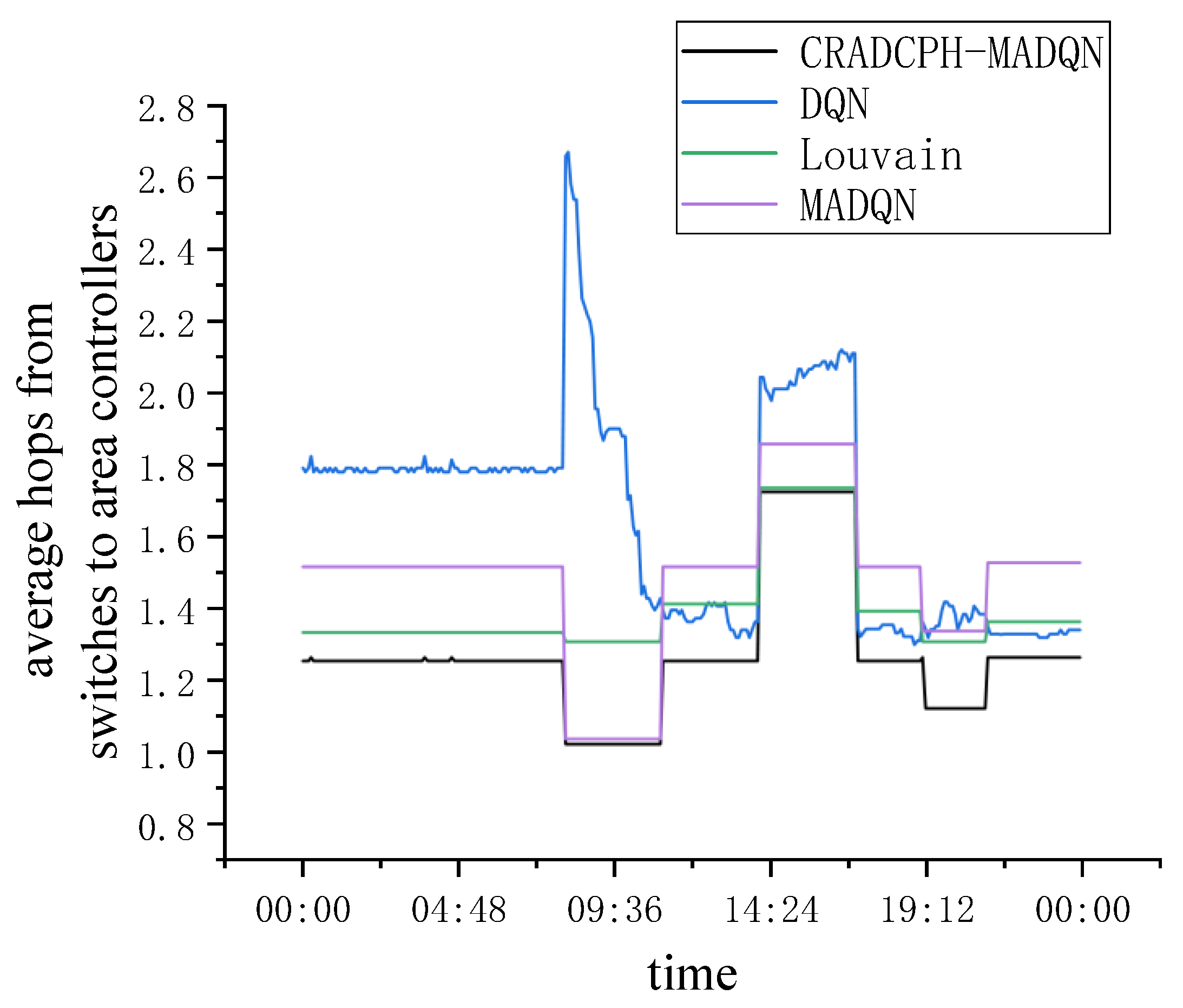
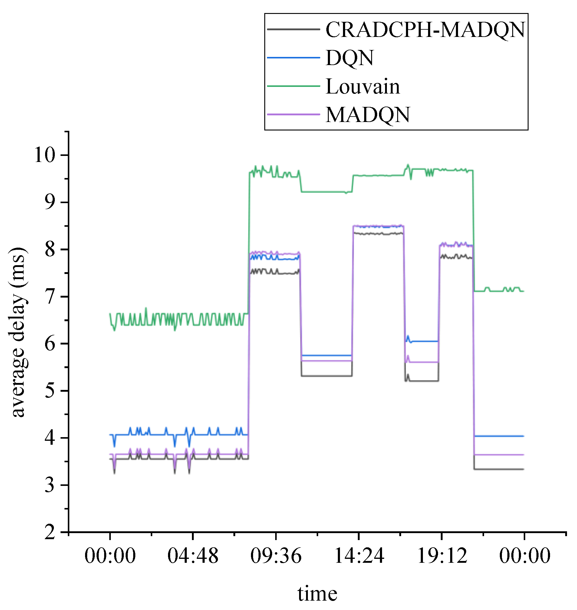
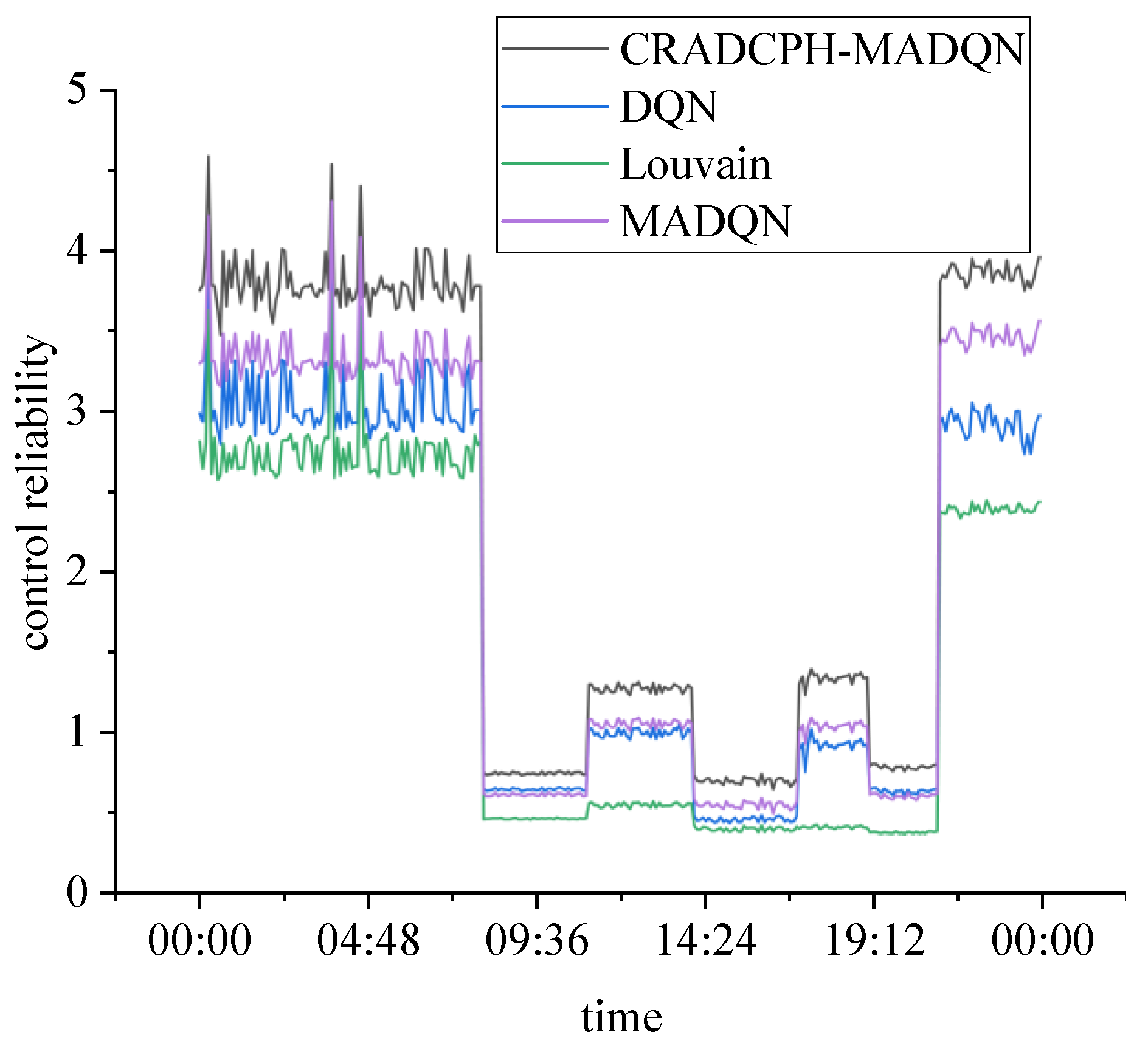
5.2. The Performance of Area Controller Placement

The average latency from the device to the area controller determines whether the area controller can receive network requests from the device in time. The load difference reflects the load difference between area controllers, and the control reliability represents the continuity of the managed network. Therefore, we will compare the performance of the area controller in terms of average delay, load difference, and average control reliability. In addition, the smaller number of hops from the switch to the area controller, the less communication between the switch and the area controller is affected by the network state.
Figure 3 shows the trend of the average delay from mobile devices to area controllers as the number of network requests and network load changes. With the change in time, the number of network requests and traffic is changing, affecting the data transmission between the mobile device and the area controller. The experimental results of the proposed algorithm are more stable than the others because the number of network requests and the network load varies significantly at different times, and the algorithm in this paper can dynamically change the number of controllers in the network to reduce the impact of the network load to the controller load. Specifically, the average latency of the proposed algorithm is less than 9.6 ms, the average latency of the single-agent DQN-based algorithm is more than 13.7 ms, the average latency of the MADQN-based algorithm is more than 11.2 ms, the average latency of the Louvain-based algorithm is more than 12.5 ms. Therefore, the average delay of the proposed algorithm is always the lowest and varies the most smoothly. The performance of the single-agent DQN algorithm is the worst among all the algorithms because the algorithm does not change the number of controllers as the network load changes. The MADQN algorithm, which can adjust the number of controllers as the network state changes, performs significantly better than the single-agent DQN. This algorithm does not consider the variability of the number of switches with the network state. Thus, it cannot find a more suitable controller for the temporarily added switches, which results in a worse performance than the algorithm proposed in this paper. Since the Louvain-based algorithm also considers the variability of the number of switches, it sometimes performs better than MADQN.
Figure 4 represents the load difference of the controller deployment schemes of different algorithms as the network state changes. Figure 4 shows that the load difference between both the proposed algorithm and the Louvain-based algorithm in this paper is lower than the rest of the algorithms, while their load difference varies in a much flatter trend. Specifically, the maximum load difference of the proposed algorithm is about 0.5, the maximum load difference of the single-agent DQN-based algorithm is about 0.9, the maximum load difference of the MADQN-based algorithm is about 0.6, the maximum load difference of the Louvain-based algorithm is about 0.51. This shows that the impact of temporary switches on network performance is considered when the controller is deployed to find a suitable controller for the temporary switches. This also indicates that it is necessary to consider the impact of temporarily added switches on network performance in a network environment where the number of switches changes.
Figure 5 shows the results of the average control reliability of the area controllers as the network state changes. Specifically, the lowest control reliability of the proposed algorithm is more than 1.3, the lowest control reliability of the single-agent DQN-based algorithm is less than 0.9, the lowest control reliability of the MADQN-based algorithm is less than 1.2, the lowest control reliability of the Louvain-based algorithm is about 1.0. Among them, the results of the DQN- and the Louvain-based algorithm are unstable. It indicates that these two algorithms’ controller deployment strategies cannot adjust the controller reliability in time according to the network state change. The MADQN algorithm affects the algorithm’s performance because it does not consider the temporary switches. The proposed algorithm always maintains the highest value of control reliability, which can guarantee the high reliability of the control plane at all times.
Figure 6 shows the average number of hops from the managed switches to the area controller in the controllers deployed by each algorithm. In the data transmission process, the fewer hops between nodes, the less data transmission is affected by relay nodes and the less connectivity between nodes in the path. Therefore, the fewer the number of hops between nodes, the better the stability of data transmission. Among them, the DQN algorithm has the largest variation in the average number of hops. It shows that when the controllers are deployed in the case of constant network state change, it is necessary to adjust the number of controllers in time according to the network load state. In both Figure 4 and Figure 5, the performance of the proposed algorithm in this paper is the best. It indicates that the control plane deployed by the algorithm proposed in this paper can always maintain high reliability and has the best adaptability to network state changes.

5.3. The Performance of the Root Controller

After obtaining the deployment scheme of the area controller, it will also find the root controller’s suitable location according to the area controller’s deployment. The root controller is responsible for managing the entire network topology and ensuring the logical centralization of the control plane. In this section, we will compare the performance of the root controller found by different algorithms.
Figure 7 shows the average latency from area controllers to the root controller for all algorithms. Specifically, the average latency of the proposed algorithm is less than 8.4 ms, the average latency of the single-agent DQN-based algorithm is more than 8.5 ms, the average latency of the MADQN-based algorithm is more than 8.5 ms, the average latency of the Louvain-based algorithm is more than 9.8 ms. Figure 7 shows that our algorithm obtains the lowest average latency from the root controller to the area controllers. The deployment location of the root controller is based on the deployment scheme of the area controllers. Therefore, the deployment of the root controller is influenced by the area controllers. The comparison results in Figure 7 illustrate that the proposed algorithm in this paper does not affect the deployment of the root controller due to considering the variability of the number of switches. The results of the DQN algorithm are unstable. The results obtained by the Louvain-based algorithm are the worst. In addition, the results of the root controller are affected by the deployment results of area controllers. This also shows that the deployment results of area controllers obtained by the proposed algorithm are more suitable for networks with a variable number of switches.
Figure 8 shows the control reliability of the root controller obtained by all algorithms. Specifically, the lowest control reliability of the proposed algorithm is more than 0.6, the lowest control reliability of the single-agent DQN-based algorithm is less than 0.44, the lowest control reliability of the MADQN-based algorithm is less than 0.5, the lowest control reliability of the Louvain-based algorithm is about 0.37. The control reliability of the root controller deployed by all algorithms fluctuates continuously because the network transmission performance influences the reliability. Among them, the control reliability obtained by the algorithm proposed in this paper is always the highest. Figure 7 and Figure 8 illustrate that the CRADCPH-MADQN algorithm can find the root controller with the best performance and guarantee the logical centralization of the control plane and the processing of service requests across area controllers when the network state is constantly changing. In addition, the results of the root controller are affected by the deployment results of area controllers. This also shows that the deployment results of area controllers obtained by the proposed algorithm are more suitable for networks with a variable number of switches.

6. Conclusions

In this paper, we propose to solve the controller deployment problem in SD-MECCN with variable network nodes using multi-agent DQN. First, the issue of high propagation delay due to the wide coverage of the MECCN network and the high state synchronization overhead between different controllers due to the continuous movement of mobile devices. In this paper, we study the deployment of the control plane for the two-layer structure of SD-MECCN. Considering that the control plane needs to meet the requirements of low latency, low loading difference, and high reliability, we design the latency, loading difference, and reliability models and construct the optimization problem. The change in network load affects the controller load. To ensure the stability of the controller load, we designed a dynamic deployment algorithm based on multi-agent DQN. The algorithm can dynamically change the number of controllers according to the network load to ensure the stability of the controller plane load. The experimental results show that the performance of area controllers deployed by the CRADCPH-MADQN algorithm is the best in terms of delay, loading difference, and reliability. Moreover, the deployed root controllers based on the deployment results of area controllers also have the best performance. Those illustrate that it is necessary to consider the effect of node variability on the control plane in networks with variable network nodes.

Author Contributions

Conceptualization, C.X. (Chenglin Xu), C.X. (Cheng Xu), and B.L.; methodology, C.X. (Chenglin Xu) and B.L.; Simulation experiments, C.X. (Chenglin Xu) and B.L.; data reduction, C.X. (Chenglin Xu) and B.L.; writing—original draft preparation, C.X. (Chenglin Xu); writing—review and editing, C.X. (Cheng Xu); supervision, C.X. (Cheng Xu); project administration, C.X. (Cheng Xu); funding acquisition, C.X. (Cheng Xu). All authors have read and agreed to the published version of the manuscript.

Funding

This research was supported in part by the National Natural Science Foundation of China Under grant 61772185 and in part by the Fundamental Research Funds for the Central Universities of Central South University Under grant 2019zzts282.

Data Availability Statement

Not applicable.

Acknowledgments

The authors would like to thank the editors, and the reviewers for their insightful comments and suggestions.

Conflicts of Interest

The authors declare no conflict of interest.

References

  1. Zhang, Y.; Lan, X.; Ren, J.; Cai, L. Efficient Computing Resource Sharing for Mobile Edge-Cloud Computing Networks. IEEE/ACM Trans. Netw. 2020, 28, 1227–1240. [Google Scholar] [CrossRef]
  2. Tuli, S.; Ilager, S.; Ramamohanarao, K.; Buyya, R. Dynamic Scheduling for Stochastic Edge-Cloud Computing Environments Using A3C Learning and Residual Recurrent Neural Networks. IEEE Trans. Mob. Comput. 2022, 21, 940–954. [Google Scholar] [CrossRef]
  3. Du, J.; Jiang, C.; Benslimane, A.; Guo, S.; Ren, Y. SDN-Based Resource Allocation in Edge and Cloud Computing Systems: An Evolutionary Stackelberg Differential Game Approach. IEEE/ACM Trans. Netw. 2022, 30, 1613–1628. [Google Scholar] [CrossRef]
  4. Liu, J.; Shi, Y.; Zhao, L.; Cao, Y.; Sun, W.; Kato, N. Joint Placement of Controllers and Gateways in SDN-Enabled 5G-Satellite Integrated Network. IEEE J. Sel. Areas Commun. 2018, 36, 221–232. [Google Scholar] [CrossRef]
  5. Toufga, S.; Abdellatif, S.; Assouane, H.; Owezarski, P.; Villemur, T. Towards dynamic controller placement in software defined vehicular networks. Sensors 2020, 20, 1701. [Google Scholar] [CrossRef] [PubMed] [Green Version]
  6. Li, B.; Deng, X.; Deng, Y. Mobile-edge computing-based delay minimization controller placement in SDN-IoV. Comput. Netw. 2021, 193, 108049. [Google Scholar] [CrossRef]
  7. Hou, X.; Muqing, W.; Bo, L.; Yifeng, L. Multi-Controller Deployment Algorithm in Hierarchical Architecture for SDWAN. IEEE Access 2019, 7, 65839–65851. [Google Scholar] [CrossRef]
  8. Maity, I.; Dhiman, R.; Misra, S. MobiPlace: Mobility-Aware Controller Placement in Software-Defined Vehicular Networks. IEEE Trans. Veh. Technol. 2021, 70, 957–966. [Google Scholar] [CrossRef]
  9. Luong, N.C.; Hoang, D.T.; Gong, S.; Niyato, D.; Wang, P.; Liang, Y.C.; Kim, D.I. Applications of Deep Reinforcement Learning in Communications and Networking: A Survey. IEEE Commun. Surv. Tutor. 2019, 21, 3133–3174. [Google Scholar] [CrossRef] [Green Version]
  10. Li, B.; Deng, X.; Chen, X.; Deng, Y.; Yin, J. MEC-Based Dynamic Controller Placement in SD-IoV: A Deep Reinforcement Learning Approach. IEEE Trans. Veh. Technol. 2022, 71, 10044–10058. [Google Scholar] [CrossRef]
  11. Wu, Y.; Zhou, S.; Wei, Y.; Leng, S. Deep Reinforcement Learning for Controller Placement in Software Defined Network. In Proceedings of the IEEE INFOCOM 2020—IEEE Conference on Computer Communications Workshops (INFOCOM WKSHPS), Toronto, ON, Canada, 6–9 July 2020; pp. 1254–1259. [Google Scholar]
  12. Heller, B.; Sherwood, R.; McKeown, N. The controller placement problem. In Proceedings of the First Workshop on Hot Topics in Software Defined Networks (HotSDN’12), New York, NY, USA, 13 August 2012; pp. 7–12. [Google Scholar]
  13. Zhang, T.; Bianco, A.; Giaccone, P. The role of inter-controller traffic in SDN controllers placement. In Proceedings of the 2016 IEEE Conference on Network Function Virtualization and Software Defined Networks (NFV-SDN), Palo Alto, CA, USA, 7–10 November 2016; pp. 87–92. [Google Scholar]
  14. Han, L.; Li, Z.; Liu, W.; Dai, K.; Qu, W. Minimum Control Latency of SDN Controller Placement. In Proceedings of the 2016 IEEE Trustcom/BigDataSE/ISPA, Tianjin, China, 23–26 August 2016; pp. 2175–2180. [Google Scholar]
  15. Wang, G.; Zhao, Y.; Huang, J.; Wu, Y. An Effective Approach to Controller Placement in Software Defined Wide Area Networks. IEEE Trans. Netw. Serv. Manag. 2018, 15, 344–355. [Google Scholar] [CrossRef] [Green Version]
  16. Liyanage, K.S.K.; Ma, M.; Chong, P.H.J. Controller placement optimization in hierarchical distributed software defined vehicular networks. Comput. Netw. 2018, 135, 226–239. [Google Scholar] [CrossRef]
  17. Hu, Y.; Luo, T.; Wang, W.; Deng, C. On the load balanced controller placement problem in Software defined networks. In Proceedings of the 2016 2nd IEEE International Conference on Computer and Communications (ICCC), Chengdu, China, 14–17 October 2016; pp. 2430–2434. [Google Scholar]
  18. Kaur, K.; Garg, S.; Kaddoum, G.; Kumar, N.; Gagnon, F. SDN-Based Internet of Autonomous Vehicles: An Energy-Efficient Approach for Controller Placement. IEEE Wirel. Commun. 2019, 26, 72–79. [Google Scholar] [CrossRef]
  19. Schütz, G.; Martins, J. A comprehensive approach for optimizing controller placement in Software-Defined Networks. Comput. Commun. 2020, 159, 198–205. [Google Scholar] [CrossRef]
  20. Deng, Y.; Chen, Z.; Chen, X.; Fang, Y. Throughput Maximization for Multiedge Multiuser Edge Computing Systems. IEEE Internet Things J. 2022, 9, 68–79. [Google Scholar] [CrossRef]
  21. Ouamri, M.A.; Barb, G.; Singh, D.; Alexa, F. Load Balancing Optimization in Software-Defined Wide Area Networking (SD-WAN) using Deep Reinforcement Learning. In Proceedings of the 2022 International Symposium on Electronics and Telecommunications (ISETC), Timisoara, Romania, 10–11 November 2022; pp. 1–6. [Google Scholar]
  22. Alqahtani, A.S. Performance computation and implementation of distributed controllers for reliable software-defined networks. J. Supercomput. 2021, 77, 12790–12800. [Google Scholar] [CrossRef]
  23. Xu, C.-M.; Zhang, J.-S.; Kong, L.-Q.; Jin, X.-B.; Kong, J.-L.; Bai, Y.-T.; Su, T.-L.; Ma, H.-J.; Chakrabarti, P. Prediction Model of Wastewater Pollutant Indicators Based on Combined Normalized Codec. Mathematics 2022, 10, 4283. [Google Scholar] [CrossRef]
  24. Barrett, T.; Clements, W.; Foerster, J.; Lvovsky, A. Exploratory combinatorial optimization with reinforcement learning. Proc. AAAI Conf. Artif. Intell. 2020, 34, 3243–3250. Available online: https://ojs.aaai.org/index.php/AAAI/article/view/5723 (accessed on 1 October 2022). [CrossRef]
  25. Csereoka, P.; Roman, B.-I.; Micea, M.V.; Popa, C.-A. Novel Reinforcement Learning Research Platform for Role-Playing Games. Mathematics 2022, 10, 4363. [Google Scholar] [CrossRef]
  26. Knight, S.; Nguyen, H.X.; Falkner, N.; Bowden, R.; Roughan, M. The internet topology zoo. IEEE J. Sel. Areas Commun. 2011, 29, 1765–1775. [Google Scholar] [CrossRef]
  27. Masatu, E.M.; Sinde, R.; Sam, A. Development and Testing of Road Signs Alert System Using a Smart Mobile Phone. J. Adv. Transp. 2022, 2022, 5829607. [Google Scholar] [CrossRef]
  28. Quemelli, M.B.; Brando, A.S. Handling and pushing objects using unmanned guided vehicles. Robot. Comput.-Integr. Manuf. 2020, 63, 101913. [Google Scholar] [CrossRef]
Figure 1. Control plane of the two-layer structure.
Mathematics 11 01247 g001
Figure 2. The procedure of the proposed solution.
Mathematics 11 01247 g002
Figure 3. Average delay.
Mathematics 11 01247 g003
Figure 4. Load difference.
Mathematics 11 01247 g004
Figure 5. Control reliability.
Mathematics 11 01247 g005
Figure 6. Average hops.
Mathematics 11 01247 g006
Figure 7. Root average delay.
Mathematics 11 01247 g007
Figure 8. Root control reliability.
Mathematics 11 01247 g008
Table 1. Comparison with important papers.
ResearchHierarchical Control PlaneDRLConsider Node VariabilityConsider Control Reliability
Hou et al. [7]YesNoNoNo
Wu et al. [11]NoYesNoNo
Li et al. [10]YesYesNoYes
This paperYesYesYesYes
Table 2. Important notations.
NotationDescription
Vthe set of nodes
v i the node i in the network
Nthe maximum number of nodes
Ethe set of edges between nodes
Athe set of area controllers
Ythe number of area controllers
a j the area controller j
r k the intermediate node k on the path, which is a switch
d a , b p p the propagation delay between node a and node b
d a , b t the transmission delay between node a and node b
d a q the queuing time of data in switch a
d a p c the processing time of data in the switch a
d a , b t w l the transmission delay between node a and node b, and node a and node b are wirelessly connected
d a , b t w d the transmission delay between node a and node b, and node a and node b are wired connected
B a , b w the transmission rate between node a and node b
l a j the load of the area controller a j
c v the load difference of the area controllers
C a c the control reliability C a c of controller a
D m a x a the maximum delay from the mobile device to the area controller
Δ l the load difference of the area controllers
C a the mean value of control reliability of all area controllers
C Y the control reliability of the root controller
D m a x Y the maximum delay from all area controllers to the root controller
Table 3. Simulation Parameters.
ParameterValue
the number of nodes51
the number of edges64
α 1 0.8
β 1 0.1
γ 1 0.1
α 2 0.3
γ 2 0.7
B o 100
p a 50
g a , b 13
N 11
Table 4. Number of mobile devices and network requests at different access points.
TimeItemBusy Access PointOrdinary Access PointTemporary Access Point
00:00–8:00Mobile devices(280,80)(142,39)(0,0)
Network requests(1213,277)(389,111)(0,0)
8:05–11:00Mobile devices(1266,396)(721,177)(706,128)
Network requests(3881,964)(2157,699)(2087,595)
11:05–14:00Mobile devices(1000,309)(513,154)(0,0)
Network requests(3037,673)(1458,355)(0,0)
14:05–17:00Mobile devices(1781,515)(785,215)(796,265)
Network requests(5502,1594)(2585,745)(2328,584)
17:05–19:00Mobile devices(1244,321)(500,165)(0,0)
Network requests(3479,1132)(1435,451)(0,0)
19:05–21:00Mobile devices(1655,391)(600,192)(677,214)
Network requests(4779,1180)(1741,552)(2055,520)
21:05–23:55Mobile devices(501,103)(150,48)(0,0)
Network requests(1488,452)(446,141)(0,0)
Table 5. Network traffic between different nodes.
TimeBetween Busy and BusyBetween Busy and OrdinaryBetween Ordinary and Ordinary
00:00–8:00250–350120–22040–80
8:05–11:00800–850600–650200–350
11:05–14:00600–700450–550150–250
14:05–17:00800–1000600–800200–500
17:05–19:00700–800500–600200–300
19:05–21:00800–900600–700200–400
21:05–23:55300–400150–25050–100
Disclaimer/Publisher’s Note: The statements, opinions and data contained in all publications are solely those of the individual author(s) and contributor(s) and not of MDPI and/or the editor(s). MDPI and/or the editor(s) disclaim responsibility for any injury to people or property resulting from any ideas, methods, instructions or products referred to in the content.

