Article

AI-Enabled Condition Monitoring Framework for Indoor Mobile Cleaning Robots

by
Sathian Pookkuttath
*,
Prabakaran Veerajagadheswar
and
Mohan Rajesh Elara
Engineering Product Development Pillar, Singapore University of Technology and Design (SUTD), Singapore 487372, Singapore
*
Author to whom correspondence should be addressed.
Mathematics 2023, 11(17), 3682; https://doi.org/10.3390/math11173682
Submission received: 28 June 2023 / Revised: 16 August 2023 / Accepted: 25 August 2023 / Published: 26 August 2023
(This article belongs to the Topic AI and Data-Driven Advancements in Industry 4.0)

Abstract

:
Autonomous mobile cleaning robots are ubiquitous today and have a vast market need. Current studies are mainly focused on autonomous cleaning performances, and there exists a research gap on monitoring the robot’s health and safety. Vibration is a key indicator of system deterioration or external factors causing accelerated degradation or threats. Hence, this work proposes an artificial intelligence (AI)-enabled automated condition monitoring (CM) framework using two heterogeneous sensor datasets to predict the sources of anomalous vibration in mobile robots with high accuracy. This allows triggering proper maintenance or corrective actions based on the condition of the robot’s health or workspace, easing condition-based maintenance (CbM). Anomalous vibration sources are classified as induced by uneven Terrain, Collision with obstacles, loose Assembly, and unbalanced Structure, which causes accelerated system deterioration or potential hazards. Here, an unexplored heterogeneous sensor dataset using inertial measurement unit (IMU) and current sensors is proposed for effective recognition across different vibration classes, resulting in higher-accuracy prediction. A simple-structured 1D convolutional neural network (1D CNN) is developed for training and real-time prediction. A 2D CbM map is generated by fusing the predicted classes in real time on an occupancy grid map of the workspace to monitor the conditions of the robot and workspace remotely. The evaluation test results of the proposed method show that the usage of heterogeneous sensors performs significantly more accurately (98.4%) than previous studies, which used IMU (92.2%) and camera (93.8%) sensors individually. Also, this model is comparatively fast, fit for the environment, and ideal for real-time applications in mobile robots based on field trial validations, enhancing mobile robots’ productivity and operational safety.

1. Introduction

The demand for autonomous professional indoor cleaning robots keeps increasing due to frequent cleaning and disinfection of large workplaces, especially after the COVID-19 pandemic, and due to labor issues such as availability, cost, efficiency, and infection risks. In [1], it is predicted that 48.6 million cleaning robot units will be sold in 2023. Also, [2] shows a growth projection of the cleaning robot market to USD 25.9 billion by 2027 from USD 9.8 billion in 2022. As a support to this industry, many technological enhancements works have been conducted recently to improve autonomous and functional efficiency, primarily perception [3,4], path planning [5,6], area coverage [7,8], energy saving [9,10], and cleaning performance assessment [11,12]. However, a significant research gap observed for mobile cleaning robots is that little work has been conducted on developing an automated condition monitoring (CM) framework considering both internal and external factors that affect the robot’s health and operational safety. Such a CM framework can enable maintenance strategies such as condition-based maintenance (CbM), i.e., maintenance only when needed, based on the robot’s condition or workspace. This CM framework in addition to CbM is crucial to avoid catastrophic failure, malfunction, environmental hazards, downtime, under-utilization of components, higher maintenance cost, and customer dissatisfaction. The execution of such an automated CM framework is also paramount by considering the enormous requirements of cleaning robots and opting for a suitable rental strategy for manufacturers or cleaning contract companies, followed by a fixed rental policy [13] for deployment irrespective of workspace conditions. Inertial measurement unit (IMU) sensors are versatile, especially for vibration-based applications, not only for robots but for human motion studies as well [14,15]. However, heterogeneous data are preferred for effective CM application in mobile robots with high-accuracy prediction, which complement each other during different scenarios affecting the robot’s health and operational safety. Hence, this research proposes an unexplored heterogeneous sensor dataset-based automated CM framework using IMU and current sensors for indoor mobile robots facilitating real-time CbM and applying deep learning (DL) techniques.

1.1. Problem Statement

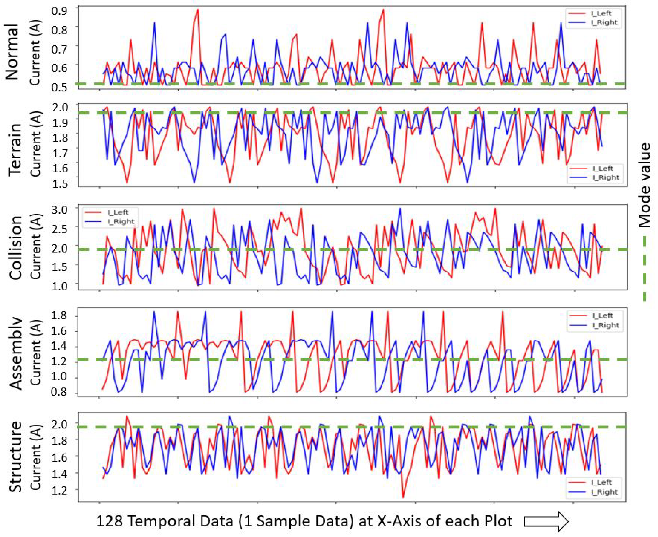
All mobile robots deteriorate naturally after long-term continuous usage, mainly due to wear and tear, loosening subassemblies such as wheel couplings, sensors, etc., and fail in their operational and functional capabilities, even if deployed in the intended environment. However, other reasons that accelerate the system degradation rate include unbalanced structural loading or deployment on uneven terrains, such as tactile pavers, pebble pathways, and damaged tiles. Collision with obstacles due to sensor limitations, faults, and inaccuracies also causes accelerated system failure or becomes hazardous, for example, LiDAR sensors’ limit to detecting glass doors, as mentioned in [16,17], and also sometimes miss detecting thin metal legs of tables or unseen low-height table bases. Here, vibration is the common decisive element for system degradation and threats, and such anomalous vibration sources are mainly terrain, collision, assembly, and structure induced. Also, one vibration source may lead to another unless prompt maintenance action is taken. For instance, continuous drive on an uneven terrain causes the loose assembly of system components. Early identification of such abnormal vibration sources will help to assess and fix system level deterioration promptly, avoiding catastrophic failure, isolate or redirect the robot from the hazardous workspaces, plan for a robot-friendly workspace, improve design and assembly, etc. Hence, detecting the characteristics of vibration types using onboard sensors and predicting the sources of such anomalous vibrations using an easily executable DL technique is critical in mobile robots. Towards this, we introduced a vibration-based automated CM framework enabling CbM in previous works using an IMU sensor [18] and monocular camera sensor [19] individually. The camera-based study was better than the IMU-based study in real-time prediction time and accuracy. However, camera-based work is not recommended for dark/shadow environments; also, the camera lens’s glass cover cleanliness is to be assured in a dusty cleaning environment. In both studies, the accuracy of vibration source prediction needs to improve significantly to ensure the correct maintenance action is placed; otherwise, it raises additional downtime and maintenance costs. We observed the robot’s behavior during the IMU and camera-based studies, and it was found that that, sometimes, there was no apparent vibration in the Collision and Structure classes, being wrongly predicted as the Normal class. At the same time, the robot kept trying to overcome the affected/abnormal load or obstacles. Therefore, IMU and camera sensors are often limited to accurately predicting these classes. Hence, more studies are essential for a higher-accuracy CM framework to execute in indoor mobile robots, assuring the robot’s health and operational safety by exploring heterogeneous sensors with unique data features.

1.2. Related Works

In the literature, vibration-based health monitoring studies by analyzing the characteristics of vibration data for fault detection, classification, and prediction have been mainly conducted for machine components or systems such as bearings [20], motors [21], machines [22,23], and structural systems [24]. Condition monitoring and fault diagnosis studies were also conducted for industrial robots, for example, to reduce downtime in a wafer transfer robot [25], predicting failure in a packaging robot [26], safe stop prediction in a collaborative robot [27], etc. The advent of artificial intelligence (AI) has enhanced fault diagnosis and prediction, and out of various techniques, the 1D convolutional neural network (1D CNN) was found prominent due to its simple structure, fast inferencing, computationally lower cost, and better prediction accuracy, making it suitable for real-time applications [28]. The advantage of the 1D CNN model has also been verified in previous works [18,19], showing a better accuracy and inference time compared to other common approaches such as long short-term memory (LSTM), CNN-LSTM, multilayer perceptron (MLP), and support vector machine (SVM). The type of sensor generally used for collecting vibration data in various systems are micro-electromechanical systems (MEMS) or piezoelectric accelerometers [20,29,30,31]. The studies described above show that vibration-based CM research has been scarcely conducted for wheeled mobile autonomous robots, especially for cleaning applications. Also, the different onboard typical sensors and their configurations are to be explored more for high-accuracy real-time condition monitoring applications in mobile robots.
Competitive (independent measurement of the same property), complementary (different measures complement each other, resolving the shortcomings of each sensor), and cooperative (originate data from two sensors) sensor fusion techniques are used in mobile robots for state estimation, localization, and navigation [32]. For instance, a camera visual system and robot odometry fusion method are proposed in [33] using the Kalman filter (KF), resulting in better localization accuracy in mobile robots compared to tests conducted with each sensor data used separately. In [34], the authors simulated fusing odometry and sonar sensor data for mobile robot navigation to improve position estimation and correct systematic error using the extended Kalman filter (EKF) and the adaptive fuzzy logic system (AFLS). A sensor fusion method to reduce position errors and better target tracking for mobile robots is proposed in [35] using an encoder, an inertial sensor, and active beacon sensors and applying the unscented Kalman filter (UKF). However, such sensor fusion techniques mostly needed extensive system modeling and calibration processes of statistical filtering techniques. To avoid such expensive approaches, recently, techniques have been applied, such as the long short-term memory (LSTM) model adapted in [36] for learning fused camera pose and IMU data. Another DL method, VINet architecture, is proposed by fusing camera and IMU data in [37] for visual–inertial odometry motion estimation. Similarly, a hybrid framework, recurrent convolutional neural network (RCNN), is developed in [38] for higher accuracy and robustness in the localization of mobile robots, fusing a 2D laser scanner and IMU sensor data.
In the literature, existing terrain classification works for mobile robots have been been conducted to detect the terrain type for traversability analysis, using onboard proprioceptive and exteroceptive sensors, including wheel–terrain interactive and noninteractive works. These are primarily conducted using IMU sensor-based vibration data and suitable classifiers. For instance, adaptive terrain classification using an IMU sensor to classify grass, small and large gravel, and hard grounds at different operating speeds with the random forest classifier in [39] observed an average accuracy of 93%. Five types of typical indoor terrains, including different tiles and carpets, are classified based on IMU acceleration and angular velocity data in [40] using a linear Bayes normal classifier, and a prediction accuracy of around 89% was found. Similarly, in [41], the authors used the magnitude frequency response on X- and Y-axis rotation and Z-axis acceleration data captured through an IMU sensor to classify dirt, gravel/grass, asphalts, and mud using the classifier probabilistic neural network (PNN) and found an accuracy around 84% considering different driving speeds as well. Similarly, different terrain types such as concrete, pebble, grass, paving stone, sand, and synthetic running track are classified using IMU gyroscope and accelerometer data and applying the multilayer perceptron (MLP) neural network in [42], resulted in a prediction accuracy of 97.18 to 99.7 with different processing window sizes. In [43], the authors used a combination of IMU vibration and camera-image-based data for the classification of fourteen types of outdoor terrains using an SVM classifier and found an average accuracy of 87.33%. These terrain classification studies may help CM applications for the external terrain-induced vibration source class. However, other factors/classes we proposed for CM, such as collision, loose assembly, and unbalanced structure affecting the robot’s failure or potential hazards, are still unsolved.
Current sensors are the least exploited sensors for mobile robot applications other than energy consumption or energy-efficient strategy studies for navigation in different trajectories, as addressed in [44,45]. Motor current signature analysis (MCSA) is one of the earliest fault diagnosis approaches in motor-driven equipment by monitoring the changes in current readings [46]. However, as per our knowledge, integrating a current sensor either individually or with other onboard sensors for condition monitoring applications in mobile robots has not been explored.

1.3. Contributions

The key contributions of this study are listed below:
  • An unexplored and compelling heterogeneous sensor dataset-based CM framework is developed for mobile robots using IMU and current sensors, resolving the shortcomings of individual sensors in detecting anomalous vibration class features.
  • Vibration-affected data are modeled by formulating an algorithm to ensure the temporal data from IMU and current sensors are subscribed and fused concurrently.
  • Vibration data are trained by developing a simple, fast, and low-computation-cost 1D CNN model for real-time prediction of the internal and external anomalous vibration sources that cause system degradation and operational hazards.
  • A vibration source mapping framework is developed, which fuses the predicted vibration classes on the 2D occupancy grid of the environment in real time, generating a 2D CbM map that enables prompt CbM or corrective actions for the robot’s workspace.
  • Based on the case study results, the proposed heterogeneous sensor-based CM framework is ideal for mobile robots for real-time CbM applications, with a significant improvement in prediction accuracy compared to previous works where IMU and camera sensors were used individually.
The remainder of this paper is organized as follows. Section 2 shows an overview of the proposed work. Section 3 elaborates on the experiments and results, including a detailed comparison with previous works. Section 4 explains the field case studies for real-time application, and a conclusion is presented in Section 5.

2. Overview of the Proposed Framework

The overview of the proposed heterogeneous sensor dataset-based anomalous vibration source prediction framework for the CM of autonomous mobile indoor cleaning robots enabling CbM is illustrated in Figure 1, and the details of each module are explained as follows.

2.1. Mobile Robot Test Platform and Vibration Source Classes

An in-house-developed autonomous steam mopping and disinfection robot suitable for large indoor workplaces is used in this study for data acquisition and real-time case studies. The photos of this wheeled mobile robot with critical components are shown in Figure 2. The maximum size of the robot is 45(L) × 40(W) × 38(H) cm and around 20 kg weight, including the cleaning payload. The robot chassis is built using an aluminum plate and extruded channels for a robust structure, and all the electromechanical and sensor assemblies are fastened to the chassis for smooth and stable locomotion across all the typical indoor floors. A differential wheel drive mechanism is used with two caster wheel supports. Two Oriental motors of 24 V and 1.9 N-m torque brushless DC geared motors (BLHM015K-50) are used for each drive wheel with a closed-loop control function. An RPLiDAR A2 scanner is mounted at the top of the robot with 360 coverage for localization and mapping. A Vectornav VN-100 IMU sensor is firmly mounted on the aluminum base plate at the center portion of the two-wheel axis, enabling navigation. A 24 V 40 Ah Li-ion battery is used to power the whole system, and an NVIDIA Jetson AGX Xavier computer is used to steer the entire operation and data storage. The robot operating system (ROS) melodic framework is used and acts as the middleware to establish all communications. More details of this robot are published in the system architecture paper [47]. A D-Link 4G/LTE mobile router is used for monitoring the robot’s health remotely. A temporary, clear acrylic cover is used to observe the system deterioration during testing.
A wheeled mobile robot generates aberrant vibration as an early symptom of failure. This could be due to various internal factors such as wear and tear, loose assembly, parts displacement or misalignment, unbalanced weight, etc., raised from the robot itself by continuous use or poor design and assembly. External factors are mainly unintended or uneven and damaged terrain, collision with undetected or unseen objects, or forced external interaction. Hence, by monitoring such abnormal vibration sources, as classified in Figure 3, appropriate maintenance actions can be triggered promptly, avoiding total system failure or incidents. Here, the Normal class is represented as the robot in healthy condition and deployed at its intended smooth operational environments, and any minor natural vibration generated is accepted.

2.2. Vibration-Affected Heterogeneous Sensors Dataset Modeling

A wheeled mobile robot vibrates at different rates linearly or in angular motion due to various vibration sources explained in the previous section. Similarly, a change in power required is observed when the robot is exposed to such undesired vibration sources, resulting in a higher current consumption compared to Normal class operation. As the vibration-affected linear or angular-motion-related data from the IMU sensor and the current consumption data from current sensors are heterogeneous, the final dataset helps to fill the gaps of individual sensors in extracting the relevant vibration-affected characteristics during various health states and exposures of the robot, which is vibration source classes. The onboard Vectornav VN-100 IMU sensor is used to extract the rate of linear and angular motion of the robot, which provides linear acceleration and angular velocity from its built-in accelerometer and gyroscope. We also added angular acceleration, calculated from angular velocity, to further strengthen the dataset features for training. A low-cost ACHS-7124 Hall-effect-based isolated linear current sensor is used with left and right drive motors and connected with an Arduino Mega 2560 microcontroller to measure the current rate consumed. These proprioceptive sensors do not depend on each other, and they are unaffected by the environment/light conditions, enabling higher accuracy in vibration class prediction. The dataset acquisition scheme, including the circuit diagram for the proposed approach, is depicted in Figure 4. (Only one current sensor motor assembly is shown for illustration.)
Here, the vibration-indicated data, mainly linear acceleration, angular velocity, and angular acceleration based on the IMU readings and the current consumed data measured from the current sensor connected with left and right drive wheel motors, all affected by the various vibration sources, are expressed in (1). As two types of sensors with different behavior are used in this study, the sequential data subscription rate is critical, and we set 80 Hz for IMU and set the same rate for the current sensor data by lowering the delay in the Arduino program and confirmed the total number of samples data collected at any particular time is same. This higher-frequency IMU subscription rate helps to reduce the vibration class prediction time to half compared to the previous individual IMU-based study without compromising the accuracy due to the complementary current sensor. The linear acceleration is measured in the X-, Y-, and Z-axes of the robot and the corresponding angular velocity and acceleration in roll (X), pitch (Y), and yaw (Z). Including the left and right motor current sensor data, a total of 11 data features are considered, and each feature is compiled with 128 temporal data (processing window size) over 1.6 s. Hence, one sample data for the 1D CNN training and prediction is set as an array of [128 × 11], as given in Expression (Section 2.2).
V i b d a t a = [ A l i n , V a n g , A a n g , I L , I R ]
A c c L i n ( X ) t 1 , A c c L i n ( X ) t 2 , A c c L i n ( X ) t 128 A c c L i n ( Y ) t 1 , A c c L i n ( Y ) t 2 , A c c L i n ( Y ) t 128 A c c L i n ( Z ) t 1 , A c c L i n ( Z ) t 2 , A c c L i n ( Z ) t 128 V e l A n g ( X ) t 1 , V e l A n g ( X ) t 2 , V e l A n g ( X ) t 128 V e l A n g ( Y ) t 1 , V e l A n g ( Y ) t 2 , V e l A n g ( Y ) t 128 V e l A n g ( Z ) t 1 , V e l A n g ( Z ) t 2 , V e l A n g ( Z ) t 128 A c c A n g ( X ) t 1 , A c c A n g ( X ) t 2 , A c c A n g ( X ) t 128 A c c A n g ( Y ) t 1 , A c c A n g ( Y ) t 2 , . . . A c c A n g ( Y ) t 128 A c c A n g ( Z ) t 1 , A c c A n g ( Z ) t 2 , A c c A n g ( Z ) t 128 I ( L ) t 1 , I ( L ) t 2 , I ( L ) t 128 I ( R ) t 1 , I ( R ) t 2 , I ( R ) t 128

2.3. 1D Convolutional Neural Network Modeling

A simple, effective, fast, and computationally low-cost neural network is crucial for real-time condition monitoring and predicting the vibration source classes. Hence, we adapted a 1D convolutional neural network model following the convolution operations on data vectors as expressed in Equations (3) and (4) [48], simplified the model structure with a minimum number of convolution layers, and opted for suitable hyperparameters to fit with our fused dataset.
Output layer c ( j ) = f i = 0 L 1 ω ( i ) x ( j i ) + b , j = 0 , 1 , . . . , N 1
This nonlinear activation function convolves the input vector to the output layer using a filter vector. Here, x (of length N) = input data vector, ω (of length L) = filter vector, term b = bias to best fit for given data, and c = output layer (of length N − L + 1).
Max - pooling output vector d = m a x u ( m × 1 , s ) c
The max-pooling output vector d is applied after convolution layers to detect the key characteristics and reduce the number of parameters. Here, m × 1 is kernel size, u is a window function, and s is a filter moving stride over input vector c.
The input vibration data for 1D CNN training is compiled into an array of [n × 128 × 11], where n is the total number of samples. Hence, the compiled/fused dataset is flattened into a 1D array [1 × 1408] and fed into 1D convolution. The convolution structure is made simple with only four layers and uses 64 filters for the first two layers and 32 for the rest. All layers used a convolution window (kernel) size of 3. The rectified linear activation unit (ReLU) is applied to each convolutional layer to learn the complex nonlinear pattern of vibration-affected heterogeneous sensor data. After each convolution layer, a max-pooling layer with a stride size of 2 is added to reduce the computation time. Further, a dropout layer is added at a rate of 0.2 for each layer to prevent over-fitting while training. Finally, the pooled feature maps are converted to a 1D array using a flattening function in the output layer to predict the multinomial probability of vibration source classes. The structure of this 1D CNN-based model proposed is illustrated in Figure 5.

2.4. 2D CbM Map for Real-Time Condition Monitoring

A 2D CbM map is generated by developing a vibration source class mapping framework to visually track the internal- and external-based anomalies in real time. This is mainly achieved by preparing a 2D environment occupancy grid map for the robot’ deployed area using the onboard RPLidar scanner and applying a grid-based mapping algorithm cartographer simultaneous localization and mapping (SLAM) with the Ceres-based scan matcher [49]. The vibration source mapping algorithm extracts each anomalous vibration class predicted and fused on the 2D occupancy grid map, as illustrated in Figure 6. Here, the robot moves from a concrete floor to a small-pebble-paved area in a corridor, and the system predicts the Terrain class continuously, which is fused on the 2D grid map instantly at the exact location where it is detected, i.e., at the geometrical coordinates of robot’s footprint, generating a 2D CbM map. The abnormal predicted classes are marked on the grid map with a unique color for each class: blue, green, orange and red for the Assembly, Structure, Terrain and Collision classes, respectively. The real-time position of the robot’s footprint is obtained from the localization data. The maintenance team can monitor remotely and trigger prompt maintenance or corrective actions based on the robot’s or workspace’s condition using a mobile app connected through the message queuing telemetry transport (MQTT) protocol.

3. Experiments, Results, and Discussion

This section elaborates on the data acquisition and visualization, 1D CNN training, evaluation and results, and comparative study with previous works and discussions.

3.1. Training Dataset Preparation and Visualization

Preparing a qualitative and quantitative training dataset representing each vibration source class for 1D CNN training and evaluation is critical in this study. Hence, we modified and exposed the robot inducing the four abnormal vibration classes. For Terrain class data, we drove the robot through typical but undesired terrain features for an indoor robot, such as small-pebble-paved and uneven/unstructured/damaged indoor floors. Similarly, exposed colliding with potentially unseen/undetected common static obstacles such as table bases, thin legs of tables, and glass doors, also externally applied forces such as collision with dynamic objects, to collect the collision-induced data. Further, various critical components were loosened for the Assembly class, such as wheel couplings, mounting brackets, and mopping heads. Finally, the robot was modified by shifting the heavy components, such as the battery, boiler assembly, etc., from their designed location, also causing an unbalanced system with a more worn-out wheel for collecting unstable Structure class vibration-affected data. The Normal class data were collected, deploying the robot in good condition in terms of the robot’s health and deployed workspace. Some of the modified and exposed cases for anomalous classes are illustrated in Figure 7. As the robot is used for steam mopping and disinfection, all the tests were performed by driving at the intended linear speed of 0.05 m/s and angular speed of 0.4 rad/s with typical cleaning patterns, mainly straight and zig-zag.
The raw data collected from both IMU and current sensors are visually represented, plotting time–amplitude and time–current graphs for each vibration source class, as shown in Figure 8 and Figure 9. This depicts the change in linear and angular motion and current consumed across the different classes. For IMU data features, the three axes’ data are plotted in the same graph, and here, the linear acceleration in the Z-axis is brought to the same scale for plotting and visualization. Similarly, current data readings from the left and right motor are plotted in the same graph. In both plots, randomly selected sample data, i.e., 128 temporal data acquired over 1.6 s, are used.
Data normalization preprocessing was performed to bring the data x into a standard scale without losing information for better convergence during 1D CNN training. Based on the data characteristics the IMU data were normalized into −1 to +1 and for the current sensor 0 to 1 using Equations (5) and (6), respectively. A total of 2500 samples [2500 × 128 × 11] for each vibration source class were collected and split into 80% for training and 20% for validation of the 1D CNN model. Additionally, 500 data samples were recorded for each class to evaluate the trained model.
IMU Dataset : x N o r m a l i s e d = 2 x m i n ( x ) m a x ( x ) m i n ( x ) 1
Current Sensor Dataset : x N o r m a l i s e d = x m i n ( x ) m a x ( x ) m i n ( x )

3.2. 1D CNN Training and Evaluation

A supervised learning strategy was applied to train the unique dataset, compiled as explained in the previous sections, using the Tensorflow DL-library [50] and the Nvidia GeForce GTX 1080 Ti-powered workstation. A K-fold (K = 5) cross-validation technique was applied for generalization and to avoid over-learning to ensure the dataset quality. Here, the datasets were split into k subsets, where k − 1 subsets are to train the model and the remaining to evaluate the model’s performance. Momentum with gradient descent optimization strategy was applied to speed up learning and help not to get stuck with local minima. We tested with different hyperparameters for training for optimum results and opted as follows. An adaptive moment optimization (Adam) optimizer [51] with a learning rate of 0.001 and an exponential decay rate of 0.9 for the first and 0.999 for the second moment was used. A categorical cross-entropy loss function was applied to assure minimum loss while compiling the model, which fits better for this multinomial classification and probability prediction. The model with a batch size of 32 and an epoch size of 80 showed better performance, as plotted in Figure 10, showing the loss and accuracy curve graphs for training and validation.
Further, the prediction accuracy of the 1D CNN model was evaluated with 500 samples that were not used during training. The assessment was performed based on the statistical metrics Accuracy, Precision, Recall, and F1 Score, as per Equations (7)–(10) [52], following the confusion matrix. Here, TP = true positive, TN = true negative, FP = false positive, and FN = false negative. This offline test statistical measure results are listed in Table 1, with an average accuracy measured as 98.4%. The approximate inference time to predict a given sample’s class measured is 0.196 milliseconds. We also tested training only with the current sensor data to understand the performance of the current sensors in predicting the vibration classes instead of the heterogeneous sensor dataset. However, the model did not converge effectively, ending with inferior accuracy of an average of 79.6% only. The offline test result (Accuracy) of each class using the current-sensor-based training is listed in Table 2.
A c c u r a c y = T P + T N T P + F P + T N + F N
P r e c i s i o n = T P T P + F P
R e c a l l = T P T P + F N
F 1 S c o r e = 2 × P r e c i s i o n × R e c a l l P r e c i s i o n + R e c a l l
As mentioned in the related works, the studies other than our previous IMU and camera-based CM studies were mainly for terrain classification, i.e., not considering the collision-related abnormality and internal health degradation, such as loose assembly and unbalanced structure. Hence, a direct comparison with such IMU-based existing terrainability studies is not appropriate. However, if only the Terrain class results of the proposed research are chosen, the prediction accuracy (98%) is much better than the works mentioned in existing terrain classification studies [39,40,41,42,43].
Beyond, we conducted a comparison study to assess the performance of the proposed 1D CNN model with other AI models, mainly SVM, MLP, LSTM, and CNN-LSTM, in terms of prediction accuracy and inference time. The same training and evaluation dataset and processing resources applied for the 1D CNN model are used here for a fair comparison. The TensorFlow library is used for training MLP, LSTM, and CNN-LSTM, whereas the Scikitlearn package is used for the SVM model. Other than for SVM, the key hyperparameter functions/values such as the Adam optimizer, a learning rate of 0.001, and categorical cross-entropy loss function are used the same as the 1D CNN model. The key parameters for the SVM model are set as C = 100 and gamma = 0.01 and applied radial basis function (RBF) kernel. The test results, prediction accuracy (average of five classes) in %, and inference time to process one sample data in milliseconds for each model, including the proposed 1D CNN model, are listed in Table 3. The comparison studies show that the selection of the optimum model depends on the application, characteristics of the data for each class identified, how the data are compiled for training, the necessity of real-time prediction, etc. Hence, a 1D CNN model is ideal for this proposed IMU–current sensor heterogeneous data-based CM framework.

3.3. Comparative Study with Our Previous CM Studies and Discussion

This section provides a performance comparison of the proposed IMU–current sensor heterogeneous dataset-based CM framework with our previous two similar but individual sensor-based CM works developed for mobile indoor robots, i.e., using a proprioceptive sensor IMU [18] and an exteroceptive sensor monocular camera [19]. The comparison study was performed based on three factors: the average prediction accuracy of the five vibration source classes, the total time from collecting a new sample data until predicting the class, and the suitability to fit with the deployed environmental conditions, mainly light and dust.
Regarding the prediction accuracy, the IMU sensor-based work found the lowest accuracy of 92.2% due to poor prediction of the Collision and Structure classes. This will raise a minor probability of triggering a wrong maintenance action, adversely affecting cost and downtime. This approach was found computationally less complex with the fastest inference time (0.162 ms) due to fewer data features and processes involved. However, the IMU subscription rate was finally set to 40 Hz to improve prediction accuracy because a higher subscription rate further reduced the accuracy. Hence, it is required to wait for a more extended period of 3.2 s to compile one data set for real-time prediction. The performance of this approach is independent of environmental conditions.
The monocular camera sensor-based study was a novel approach in terms of optical flow application for condition monitoring in mobile robots. Here, the vibration source prediction accuracy was slightly better (93.8%) than that of the IMU. However, there are still risks involved in real-time deployment, considering the few chances of triggering improper maintenance action and the consequences. This approach is computationally more complex in deriving the displacement vector data from each image frame and thereby a higher inference time from the given data sample (7.9 ms). However, the total time taken for real-time data recording and predicting a class, with a recording rate of 30 frames per second (fps), was observed the fastest around 0.2 s only. Another factor noted was the accuracy of the camera approach is affected by poor light and a dusty environment. The system fails to collect accurate vector data representing the particular class at an illuminance of less than 50 lux. Hence, the camera-based approach is not advised for places with dark shades and poorly illuminated rooms/confined areas. Also, the lens glass cover cleanliness should be assured while the robot operates in a dusty environment.
In the proposed IMU–current sensor heterogeneous dataset approach, the current sensors complement the IMU sensor’s shortcomings in accuracy and total prediction time. The distinctive higher current consumption while the robot was trying to overcome uneven terrain, obstacles, and unbalancing factors helped to extract the vibration-affected features of classes more effectively and improved the prediction accuracy of all the vibration classes. This heterogeneous dataset approach also helped to increase the IMU subscription rate twice (80 Hz) without compromising the accuracy; hence, the total time to predict a class from recording a data sample is reduced to half (1.6 s) compared to the individual IMU sensor model. Though the number of features added with two current values, the inference time (0.196 ms) is still close to the previous IMU work. Also, as both IMU and current sensors are proprioceptive, environmental changes such as light and dust are unaffected. Hence, the proposed IMU–current sensor heterogeneous sensor dataset-based CM framework is more promising for real-time deployment, especially regarding accuracy and environmental conditions. These observations and discussions are summarized in Table 4. Here, Sensor type is the sensor used indicating a single sensor or multiple sources; Accuracy is the average accuracy of five classes from model evaluation; Time taken is the approximate time consumed to predict a class, including data recording time for one sample; and Environment fit is the suitability of the approach irrespective of light and dust.
The proposed combination of IMU and current-sensor-based study shows a significant improvement in prediction accuracy of the vibration source classes compared to our previous individual IMU and camera-based studies. The higher prediction accuracy is vital for the CM applications to avoid false positive predictions and trigger improper maintenance or corrective actions. Though the camera-based work can make eight times more predictions in 1.6 s, due to the different data subscriptions and methodology developed, the close ground truth comparison study shows that such predictions are the same as the single prediction of the proposed study. Also, compared to the robot’s operating speed of 0.05 m/s, the 1.6 s for a single prediction had less impact and was acceptable from the real-time case studies conducted. Though cost-wise, the IMU sensor is expensive. It is an inevitable sensor for autonomous robots; hence, this additional application is proposed as a CM sensor together with current sensors.

4. Real-Time Field Case Studies

The proposed IMU–current-sensor-based CM framework is validated by conducting real-time case studies at four different types of indoor environments at the SUTD campus, which are the canteen and pantry area, glass-walled lobby hallway, pebble-paved indoor corridor, and our robotics lab area. It is also assured that none of these areas was used during training data sample collection.
There are two pre-works conducted for these field trials. The first is developing an Inference Engine to apply the 1D CNN model’s knowledge for inferring every new data sample in real time. Inference Engine Algorithm 1 shows the way 128 temporal data (Data) and a total of 11 sensor features (Feature) are acquired, forming a new dataset [128 × 11] for prediction. Here, a placeholder TemporalBuffer is used while collecting the dataset, and InferenceBuffer holds one complete dataset as 1D CNN input and returns the predicted vibration source class.
Algorithm 1 Inference Engine
while  F e a t u r e ,   D a t a are not empty do
       T e m p o r a l B u f f e r = call S e n s o r ( F e a t u r e , D a t a )
      Format T e m p o r a l B u f f e r to have shape (11,128)
      Append T e m p o r a l B u f f e r to I n f e r e n c e B u f f e r
       c o u n t e r F e a t u r e = c o u n t e r F e a t u r e + 1
       c o u n t e r D a t a = c o u n t e r D a t a + 1
      if  c o u n t e r F e a t u r e = = 11 , c o u n t e r D a t a = = 128  then
            I n f e r r e d C l a s s = Call 1 D C N N ( I n f e r e n c e B u f f e r )
            c o u n t e r F e a t u r e = 0
            c o u n t e r D a t a = 0
           Clean I n f e r e n c e B u f f e r
      end if
end while
Secondly, a cartographer SLAM-based 2D occupancy grid map was created for each test area. Then, a vibration source mapping algorithm (Algorithm 2) was developed, which maps the predicted abnormal vibration classes (PC) with the unique color at the center of the robot’s footprint (RFP) on the 2D grid map (map) where the class was predicted, and saved the real-time 2D CbM map with time stamp for each class fused. All the field case studies were conducted in autonomous mode at the intended speed of 0.05 m/s in a zig-zag travel pattern, ensuring a sufficiently charged battery; also, each test started verifying the robot was healthy.
Algorithm 2 Vibration Source Mapping
P C [ T e r r a i n , C o l l i s i o n , A s s e m b l y , S t r u c t u r e ]
m a p 2 D g r i d m a p
R F P [ x , y ]
D T [ D a t e , T i m e ]
if P C is Normal then  D o n o t h i n g
else if P C is Abnormal then
   if  P C is Terrain then
      C o l o r O r a n g e
   else if  P C is Collision then
      C o l o r R e d
   else if  P C is Assembly then
      C o l o r B l u e
   else if  P C is Structure then
      C o l o r G r e e n
      m a p [ R F P . x ] [ R F P . y ] c o l o r
   end if
end if
s a v e M a p m a p , D T
The first case study was conducted considering a moderately crowded place with different furniture and floor types and selected SUTD canteen and an office pantry room. The canteen floor is built with various flooring materials and features such as smooth concrete, tactile pavements, uneven wooden floors, and tables with flat bases. The canteen area was messed up with temporary cable routing, misplaced furniture, etc. Two classes of abnormal vibrations were noticed after driving through the canteen space: terrain and collision induced. The Terrain class was mainly due to the cable routing, tactile pavement, and uneven wooden floor, while the unseen table base caused the Collision class. Next, it was tested in the office pantry area with a smooth tiled floor and tall and thin metal-legged chairs. During this testing, collision-induced vibrations were predicted when the robot collided with a chair as the RPLiDAR could not detect the thin long metal leg of the chair. The robot tried to push the chair further but was blocked by a pillar with a higher current consumption, matching the training characteristics of the Collision class, though no obvious angular motion vibrations were noticed. Some of these classes fused on the SLAM map generating a 2D CbM map with the relevant trial run photos are shown in Figure 11.
The second case study was tested in a carpeted lobby hallway where one wall was built using transparent rugged glass. During the robot’s drive near the glass wall, the RPLiDAR did not precisely detect the transparent glass wall, resulting in occasionally hitting the wall. We stopped the robot to avoid damage to the robot, glass wall, and other potential hazards. Next, the robot was driven in a mixed concrete and small-pebble-paved corridor for the third field trial. During the trial runs, the Terrain-induced vibration class is predicted and fused on the map whenever the robot moves to the pebble-paved floors. As it was an isolated area with no workspace hazards, we continued the testing on the same pebble-paved floor without any maintenance action. However, after six days, intermittent Assembly-induced vibration classes were observed along with the Terrain class, mainly due to the loose assembly of wheel couplings with motors. Figure 12 shows the 2D CbM maps for case studies at the lobby and corridor, indicating some of the randomly selected fused vibration classes in real-time towards the end of the test, also the workspace photos.
Finally, we conducted a long-term test drive by isolating a small area (around 9 × 6 m 2 ) of the robotics lab with a vinyl floor and removing all obstacles, i.e., tested with no potential external factors. The robot ran continuously with timely recharging for 21 days without any abnormal classes predicted. However, apparent wheel wobbling was later observed, and Assembly-induced vibrations were fused on the SLAM map concurrently. We continued the test without any maintenance; hence, the condition worsened. Detaching the battery bracket and mopping pad assembly resulted in parts shifting and Structure-induced class prediction. These intermittent Assembly and Structure classes predicted/fused for the last few samples before stopping the robot are shown in the 2D CbM map Figure 13 with the lab test area photo.
We closely observed the robot’s behavior during these field trials, especially when it started predicting abnormal classes, and randomly collected 400 samples for each class, i.e., during Normal and all Abnormal classes, for assessing real-time prediction accuracy. The results show an average accuracy of 98.0 %. The individual class accuracy is listed in Table 5. This indicates very close prediction accuracy as the offline evaluation test results. The consistent and high prediction accuracy during the field trials shows the fitness of this proposed method for real-time deployment in professional cleaning robots for health monitoring, promptly triggering the right maintenance action and ensuring operational safety.

5. Conclusions

An automated maintenance strategy for mobile cleaning robots is essential to assure productivity and safety. The proposed heterogeneous sensor dataset-based condition monitoring framework using IMU and current sensors fills such research gaps by predicting the anomalous internal and external vibration sources, which cause system degradation or potential hazards, with high accuracy for real-time deployment. The distinctive data features of these two proprioceptive sensors were modeled as vibration data, which complement each other to sort out the flaws of individual use, resulting in a higher accuracy prediction. Also, the proposed simple, fast and low computation cost four-layer 1D CNN model was validated through four field case studies as an ideal neural network model for real-time condition monitoring applications in mobile robots by accurately predicting the abnormal vibration sources, using the proposed temporal fused dataset. Compared to similar previous works developed, the proposed work excels in accuracy, time, and fit for the environment. The IMU–current sensor heterogeneous dataset model results in 6.2% higher accuracy, and the prediction time is reduced to half compared to individual IMU sensor work. Similarly, it is 4.6% more accurate and does not affect any environment light and dust compared to the camera sensor-based study. The 2D CbM map fusing the predicted abnormal vibration source class on a SLAM-generated environment map helps the maintenance team track the system degradation of the robot, identify any operational hazards in advance, and trigger prompt maintenance or corrective actions, enabling a real-time CbM strategy. The proposed framework will also help robot manufacturers and cleaning contract companies review their maintenance and rental strategies, design and assembly processes, and plan for robot-friendly workspaces. We plan automated CM frameworks for outdoor mobile robots to extend this research.

Author Contributions

Conceptualization, S.P. and M.R.E.; methodology, S.P. and P.V.; software, P.V. and S.P.; validation, S.P.; formal analysis, S.P., M.R.E. and P.V.; investigation, S.P. and M.R.E.; resources, M.R.E.; data, S.P. and P.V.; writing–original draft preparation, S.P. and P.V.; supervision, M.R.E.; project administration, M.R.E.; funding acquisition, M.R.E. All authors have read and agreed to the published version of the manuscript.

Funding

This research is supported by the National Robotics Programme under its National Robotics Programme (NRP) BAU, Ermine III: Deployable Reconfigurable Robots, Award No. M22NBK0054 and also supported by A*STAR under its “RIE2025 IAF-PP Advanced ROS2-native Platform Technologies for Cross-sectorial Robotics Adoption (M21K1a0104)” programme.

Data Availability Statement

Data will be made available on request.

Acknowledgments

The authors would like to thank, the National Robotics Programme, the Agency for Science, Technology and Research and SUTD for their support. Thanks to Abdullah Aamir Hayat for his inputs.

Conflicts of Interest

The authors declare no conflict of interest.

References

  1. Robotics, W. World Robotics 2020 Report. Available online: http://reparti.free.fr/robotics2000.pdf (accessed on 10 August 2021).
  2. MarketsandMarkets. Cleaning Robot Market. Available online: https://marketsandmarkets.com/Market-Reports/cleaning-robot-market-22726569.html (accessed on 10 March 2023).
  3. Le, A.V.; Ramalingam, B.; Gomez, B.F.; Mohan, R.E.; Minh, T.H.Q.; Sivanantham, V. Social density monitoring toward selective cleaning by human support robot with 3D based perception system. IEEE Access 2021, 9, 41407–41416. [Google Scholar]
  4. Wang, Z.; Liao, H.; Jia, Z.; Wu, J. Semantic Mapping Based on Visual SLAM with Object Model Replacement Visualization for Cleaning Robot. In Proceedings of the 2022 IEEE International Conference on Robotics and Biomimetics (ROBIO), Jinghong, China, 5–9 December 2022; IEEE: Piscataway, NJ, USA, 2022; pp. 569–575. [Google Scholar]
  5. Ravankar, A.; Ravankar, A.A.; Watanabe, M.; Hoshino, Y.; Rawankar, A. Multi-robot path planning for smart access of distributed charging points in map. Artif. Life Robot. 2021, 26, 52–60. [Google Scholar] [CrossRef]
  6. Moon, W.; Park, B.; Nengroo, S.H.; Kim, T.; Har, D. Path planning of cleaning robot with reinforcement learning. In Proceedings of the 2022 IEEE International Symposium on Robotic and Sensors Environments (ROSE), Abu Dhabi, United Arab Emirates, 14–15 November 2022; IEEE: Piscataway, NJ, USA, 2022; pp. 1–7. [Google Scholar]
  7. Prabakaran, V.; Elara, M.R.; Pathmakumar, T.; Nansai, S. Floor cleaning robot with reconfigurable mechanism. Autom. Constr. 2018, 91, 155–165. [Google Scholar] [CrossRef]
  8. Muthugala, M.V.J.; Samarakoon, S.B.P.; Elara, M.R. Design by robot: A human-robot collaborative framework for improving productivity of a floor cleaning robot. In Proceedings of the 2022 International Conference on Robotics and Automation (ICRA), Philadelphia, PA, USA, 23–27 May 2022; IEEE: Piscataway, NJ, USA, 2022; pp. 7444–7450. [Google Scholar]
  9. Khan, A.; Noreen, I.; Habib, Z. An energy efficient coverage path planning approach for mobile robots. In Intelligent Computing, Proceedings of the 2018 Computing Conference, London, UK, 10–12 July 2018; Springer: Berlin/Heidelberg, Germany, 2019; Volume 2, pp. 387–397. [Google Scholar]
  10. Manimuthu, A.; Le, A.V.; Mohan, R.E.; Veerajagadeshwar, P.; Huu Khanh Nhan, N.; Ping Cheng, K. Energy consumption estimation model for complete coverage of a tetromino inspired reconfigurable surface tiling robot. Energies 2019, 12, 2257. [Google Scholar] [CrossRef]
  11. Zheng, K.; Chen, G.; Cui, G.; Chen, Y.; Wu, F.; Chen, X. Performance metrics for coverage of cleaning robots with mocap system. In Intelligent Robotics and Applications, Proceedings of the 10th International Conference, ICIRA 2017, Wuhan, China, 16–18 August 2017; Proceedings, Part III 10; Springer: Berlin/Heidelberg, Germany, 2017; pp. 267–274. [Google Scholar]
  12. Pathmakumar, T.; Elara, M.R.; Gómez, B.F.; Ramalingam, B. A reinforcement learning based dirt-exploration for cleaning-auditing robot. Sensors 2021, 21, 8331. [Google Scholar] [CrossRef]
  13. Chng, G. Softbank Robotics Launches First Rent-a-Robot Offering for Cleaning Services in Singapore. Available online: https://www.techgoondu.com/2019/09/25/softbank-robotics-launches-first-rent-a-robot-offering-for-cleaning-services-in-singapore/ (accessed on 28 November 2021).
  14. Cardarelli, S.; di Florio, P.; Mengarelli, A.; Tigrini, A.; Fioretti, S.; Verdini, F. Magnetometer-free sensor fusion applied to pedestrian tracking: A feasibility study. In Proceedings of the 2019 IEEE 23rd International Symposium on Consumer Technologies (ISCT), Ancona, Italy, 19–21 June 2019; IEEE: Piscataway, NJ, USA, 2019; pp. 238–242. [Google Scholar]
  15. Yang, S.; Garg, N.P.; Gao, R.; Yuan, M.; Noronha, B.; Ang, W.T.; Accoto, D. Learning-Based Motion-Intention Prediction for End-Point Control of Upper-Limb-Assistive Robots. Sensors 2023, 23, 2998. [Google Scholar] [CrossRef]
  16. Tibebu, H.; Roche, J.; De Silva, V.; Kondoz, A. Lidar-based glass detection for improved occupancy grid mapping. Sensors 2021, 21, 2263. [Google Scholar] [CrossRef]
  17. Foster, P.; Sun, Z.; Park, J.J.; Kuipers, B. Visagge: Visible angle grid for glass environments. In Proceedings of the 2013 IEEE International Conference on Robotics and Automation, Karlsruhe, Germany, 6–10 May 2013; IEEE: Piscataway, NJ, USA, 2013; pp. 2213–2220. [Google Scholar]
  18. Pookkuttath, S.; Rajesh Elara, M.; Sivanantham, V.; Ramalingam, B. AI-Enabled Predictive Maintenance Framework for Autonomous Mobile Cleaning Robots. Sensors 2022, 22, 13. [Google Scholar] [CrossRef]
  19. Pookkuttath, S.; Gomez, B.F.; Elara, M.R.; Thejus, P. An optical flow-based method for condition-based maintenance and operational safety in autonomous cleaning robots. Expert Syst. Appl. 2023, 222, 119802. [Google Scholar] [CrossRef]
  20. Eren, L.; Ince, T.; Kiranyaz, S. A generic intelligent bearing fault diagnosis system using compact adaptive 1D CNN classifier. J. Signal Process. Syst. 2019, 91, 179–189. [Google Scholar] [CrossRef]
  21. Ince, T.; Kiranyaz, S.; Eren, L.; Askar, M.; Gabbouj, M. Real-time motor fault detection by 1-D convolutional neural networks. IEEE Trans. Ind. Electron. 2016, 63, 7067–7075. [Google Scholar] [CrossRef]
  22. Tiboni, M.; Remino, C.; Bussola, R.; Amici, C. A review on vibration-based condition monitoring of rotating machinery. Appl. Sci. 2022, 12, 972. [Google Scholar] [CrossRef]
  23. Luo, B.; Wang, H.; Liu, H.; Li, B.; Peng, F. Early fault detection of machine tools based on deep learning and dynamic identification. IEEE Trans. Ind. Electron. 2018, 66, 509–518. [Google Scholar] [CrossRef]
  24. Abdeljaber, O.; Avci, O.; Kiranyaz, S.; Gabbouj, M.; Inman, D.J. Real-time vibration-based structural damage detection using one-dimensional convolutional neural networks. J. Sound Vib. 2017, 388, 154–170. [Google Scholar] [CrossRef]
  25. Kim, H.G.; Yoon, H.S.; Yoo, J.H.; Yoon, H.I.; Han, S.S. Development of predictive maintenance technology for wafer transfer robot using clustering algorithm. In Proceedings of the 2019 International Conference on Electronics, Information, and Communication (ICEIC), Auckland, New Zealand, 22–25 January 2019; IEEE: Piscataway, NJ, USA, 2019; pp. 1–4. [Google Scholar]
  26. Onur, K.; Kaymakci, O.T.; Mercimek, M. Advanced Predictive Maintenance with Machine Learning Failure Estimation in Industrial Packaging Robots. In Proceedings of the 2020 International Conference on Development and Application Systems (DAS), Suceava, Romania, 21–23 May 2020; IEEE: Piscataway, NJ, USA, 2020; pp. 1–6. [Google Scholar]
  27. Aliev, K.; Antonelli, D. Proposal of a monitoring system for collaborative robots to predict outages and to assess reliability factors exploiting machine learning. Appl. Sci. 2021, 11, 1621. [Google Scholar] [CrossRef]
  28. Kiranyaz, S.; Avci, O.; Abdeljaber, O.; Ince, T.; Gabbouj, M.; Inman, D.J. 1D convolutional neural networks and applications: A survey. Mech. Syst. Signal Process. 2021, 151, 107398. [Google Scholar] [CrossRef]
  29. Janssens, O.; Slavkovikj, V.; Vervisch, B.; Stockman, K.; Loccufier, M.; Verstockt, S.; Van de Walle, R.; Van Hoecke, S. Convolutional neural network based fault detection for rotating machinery. J. Sound Vib. 2016, 377, 331–345. [Google Scholar] [CrossRef]
  30. Kumar, P.; Shankar Hati, A. Convolutional neural network with batch normalisation for fault detection in squirrel cage induction motor. IET Electr. Power Appl. 2021, 15, 39–50. [Google Scholar] [CrossRef]
  31. Abdeljaber, O.; Sassi, S.; Avci, O.; Kiranyaz, S.; Ibrahim, A.A.; Gabbouj, M. Fault detection and severity identification of ball bearings by online condition monitoring. IEEE Trans. Ind. Electron. 2018, 66, 8136–8147. [Google Scholar] [CrossRef]
  32. Alatise, M.B.; Hancke, G.P. A review on challenges of autonomous mobile robot and sensor fusion methods. IEEE Access 2020, 8, 39830–39846. [Google Scholar] [CrossRef]
  33. Mikulová, Z.; Duchoň, F.; Dekan, M.; Babinec, A. Localization of mobile robot using visual system. Int. J. Adv. Robot. Syst. 2017, 14, 1729881417736085. [Google Scholar] [CrossRef]
  34. Sasiadek, J.; Hartana, P. Sensor data fusion using Kalman filter. In Proceedings of the Third International Conference on Information Fusion, Sun City, South Africa, 1–4 November 2020; IEEE: Piscataway, NJ, USA, 2000; Volume 2, pp. WED5–WED19. [Google Scholar]
  35. Shaikh, M.M.; Bahn, W.; Lee, C.; Kim, T.i.; Lee, T.J.; Kim, K.S.; Cho, D. Mobile robot vision tracking system using unscented Kalman filter. In Proceedings of the 2011 IEEE/SICE International Symposium on System Integration (SII), Kyoto, Japan, 20–22 December 2011; IEEE: Piscataway, NJ, USA, 2011; pp. 1214–1219. [Google Scholar]
  36. Rambach, J.R.; Tewari, A.; Pagani, A.; Stricker, D. Learning to fuse: A deep learning approach to visual-inertial camera pose estimation. In Proceedings of the 2016 IEEE International Symposium on Mixed and Augmented Reality (ISMAR), Merida, Yucatan, Mexico, 19–23 September 2016; IEEE: Piscataway, NJ, USA, 2016; pp. 71–76. [Google Scholar]
  37. Clark, R.; Wang, S.; Wen, H.; Markham, A.; Trigoni, N. Vinet: Visual-inertial odometry as a sequence-to-sequence learning problem. In Proceedings of the AAAI Conference on Artificial Intelligence, San Francisco, CA, USA, 4–9 February 2017; Volume 31. [Google Scholar]
  38. Li, C.; Wang, S.; Zhuang, Y.; Yan, F. Deep sensor fusion between 2D laser scanner and IMU for mobile robot localization. IEEE Sens. J. 2019, 21, 8501–8509. [Google Scholar] [CrossRef]
  39. Wang, M.; Ye, L.; Sun, X. Adaptive online terrain classification method for mobile robot based on vibration signals. Int. J. Adv. Robot. Syst. 2021, 18, 17298814211062035. [Google Scholar] [CrossRef]
  40. Tick, D.; Rahman, T.; Busso, C.; Gans, N. Indoor robotic terrain classification via angular velocity based hierarchical classifier selection. In Proceedings of the 2012 IEEE International Conference on Robotics and Automation, St Paul, MN, USA, 14–18 May 2012; IEEE: Piscataway, NJ, USA, 2012; pp. 3594–3600. [Google Scholar]
  41. Dupont, E.M.; Moore, C.A.; Collins, E.G.; Coyle, E. Frequency response method for terrain classification in autonomous ground vehicles. Auton. Robot. 2008, 24, 337–347. [Google Scholar] [CrossRef]
  42. Csík, D.; Odry, Á.; Sárosi, J.; Sarcevic, P. Inertial sensor-based outdoor terrain classification for wheeled mobile robots. In Proceedings of the 2021 IEEE 19th International Symposium on Intelligent Systems and Informatics (SISY), Subotica, Serbia, 16–18 September 2021; IEEE: Piscataway, NJ, USA, 2021; pp. 159–164. [Google Scholar]
  43. Weiss, C.; Tamimi, H.; Zell, A. A combination of vision-and vibration-based terrain classification. In Proceedings of the 2008 IEEE/RSJ International Conference on Intelligent Robots and Systems, Nice, France, 22–26 September 2008; IEEE: Piscataway, NJ, USA, 2008; pp. 2204–2209. [Google Scholar]
  44. Constantin, G.; Maroșan, I.A.; Crenganiș, M.; Botez, C.; Gîrjob, C.E.; Biriș, C.M.; Chicea, A.L.; Bârsan, A. Monitoring the Current Provided by a Hall Sensor Integrated in a Drive Wheel Module of a Mobile Robot. Machines 2023, 11, 385. [Google Scholar] [CrossRef]
  45. Rapalski, A.; Dudzik, S. Energy Consumption Analysis of the Selected Navigation Algorithms for Wheeled Mobile Robots. Energies 2023, 16, 1532. [Google Scholar] [CrossRef]
  46. Kryter, R.; Haynes, H. Condition Monitoring of Machinery Using Motor Current Signature Analysis; Technical Report; Oak Ridge National Lab.: Oak Ridge, TN, USA, 1989. [Google Scholar]
  47. Pookkuttath, S.; Elara, M.R.; Mohan Rayguru, M.; Saldi, Z.S.; Sivanantham, V.; Ramalingam, B. Snail: An Eco-Friendly Autonomous Steam Mopping Robot for Cleaning and Disinfection of Floors. Mathematics 2023, 11, 1086. [Google Scholar] [CrossRef]
  48. Mitiche, I.; Nesbitt, A.; Conner, S.; Boreham, P.; Morison, G. 1D-CNN based real-time fault detection system for power asset diagnostics. IET Gener. Transm. Distrib. 2020, 14, 5766–5773. [Google Scholar] [CrossRef]
  49. Hess, W.; Kohler, D.; Rapp, H.; Andor, D. Real-time loop closure in 2D LIDAR SLAM. In Proceedings of the 2016 IEEE International Conference on Robotics and Automation (ICRA), Stockholm, Sweden, 16–21 May 2016; IEEE: Piscataway, NJ, USA, 2016; pp. 1271–1278. [Google Scholar]
  50. Abadi, M.; Barham, P.; Chen, J.; Chen, Z.; Davis, A.; Dean, J.; Devin, M.; Ghemawat, S.; Irving, G.; Isard, M.; et al. Tensorflow: A system for large-scale machine learning. In Proceedings of the Osdi, Savannah, GA, USA, 2–4 November 2016; Volume 16, pp. 265–283. [Google Scholar]
  51. Kingma, D.P.; Ba, J. Adam: A method for stochastic optimization. arXiv 2014, arXiv:1412.6980. [Google Scholar]
  52. Grandini, M.; Bagli, E.; Visani, G. Metrics for multi-class classification: An overview. arXiv 2020, arXiv:2008.05756. [Google Scholar]
Figure 1. Overview of the heterogeneous sensor dataset-based CM framework for mobile robots.
Mathematics 11 03682 g001
Figure 2. Test platform. Autonomous steam mopping robot.
Mathematics 11 03682 g002
Figure 3. Vibration source classes in a wheeled mobile robot.
Mathematics 11 03682 g003
Figure 4. Heterogeneous sensor dataset acquisition scheme.
Mathematics 11 03682 g004
Figure 5. One-dimensional (1D) CNN structure and data shape modeled for training.
Mathematics 11 03682 g005
Figure 6. Anomalous class prediction and 2D CbM map generation.
Mathematics 11 03682 g006
Figure 7. Robot set-up for vibration-affected training data acquisition for abnormal classes.
Mathematics 11 03682 g007
Figure 8. Vibration-affected data from IMU sensor for each class.
Mathematics 11 03682 g008
Figure 9. Vibration-affected data from current sensor for each class.
Mathematics 11 03682 g009
Figure 10. Loss and Accuracy curves for Training and Validation.
Mathematics 11 03682 g010
Figure 11. Two-dimensional (2D) CbM map. Canteen and Pantry area: Case study 1.
Mathematics 11 03682 g011
Figure 12. Two-dimensional (2D) CbM maps. Lobby and Corridor area: Case Studies 2 and 3.
Mathematics 11 03682 g012
Figure 13. Two-dimensional (2D) CbM map. Robotics Lab area: Case Study 4.
Mathematics 11 03682 g013
Table 1. One-dimensional (1D) CNN model evaluation result: IMU and current sensor heterogeneous dataset based.
Vibration ClassPrecisionRecallF1 ScoreAccuracy
Normal0.990.980.990.99
Terrain0.980.960.980.98
Collision0.990.990.980.99
Assembly0.990.960.970.98
Structure0.980.970.990.98
Table 2. One-dimensional (1D) CNN model evaluation result: only current sensor based.
Vibration ClassNormalTerrainCollisionAssemblyStructure
Accuracy Prediction (%)7885817480
Table 3. Comparison with other AI models.
ModelAccuracy (%)Inference Time (ms)
1D CNN98.40.196
CNN-LSTM94.20.368
LSTM90.60.314
MLP84.30.205
SVM82.91.985
Table 4. Performance comparison with previous works proposed.
Sensor TypeAccuracyTime TakenEnvironment Fit
IMU + current sensor98.4%1.6 sExcellent
Monocular camera [19]93.8%0.2 sFair
IMU [18]92.2%3.2 sExcellent
Table 5. Real-time prediction accuracy of vibration sources.
Vibration ClassNormalTerrainCollisionAssemblyStructure
Accuracy Prediction (%)9998999896
Disclaimer/Publisher’s Note: The statements, opinions and data contained in all publications are solely those of the individual author(s) and contributor(s) and not of MDPI and/or the editor(s). MDPI and/or the editor(s) disclaim responsibility for any injury to people or property resulting from any ideas, methods, instructions or products referred to in the content.

