Article

Mathematical Methods for an Accurate Navigation of the Robotic Telescopes

by
Vadym Savanevych
1,
Sergii Khlamov
2,*,
Oleksandr Briukhovetskyi
3,
Tetiana Trunova
2 and
Iryna Tabakova
2
1
Department of Systems Engineering, Kharkiv National University of Radio Electronics, Nauki Ave., 14, 61166 Kharkiv, Ukraine
2
Department of Media Systems and Technologies, Kharkiv National University of Radio Electronics, Nauki Ave., 14, 61166 Kharkiv, Ukraine
3
Western Center of Radio Engineering Surveillance, National Space Facilities Control and Test Center, Kosmonavtov Str., 896112 Mukacheve, Ukraine
*
Author to whom correspondence should be addressed.
Mathematics 2023, 11(10), 2246; https://doi.org/10.3390/math11102246
Submission received: 31 March 2023 / Revised: 24 April 2023 / Accepted: 29 April 2023 / Published: 11 May 2023
(This article belongs to the Special Issue Mathematics in Robot Control for Theoretical and Applied Problems)

Abstract

:
Accurate sky identification is one of the most important functions of an automated telescope mount. The more accurately the robotic telescope is navigated to the investigated part of the sky, the better the observations and discoveries made. In this paper, we present mathematical methods for accurate sky identification (celestial coordinates determination). They include the automatic selection of the reference stars, preliminary and full sky identification, as well as an interaction with international databases, which are a part of the astrometric calibration. All described methods help to receive accurately calculated astrometric data and use it for the positional calibration and better navigation of the automated telescope mount. The developed methods were successfully implemented in the Collection Light Technology (CoLiTec) software. Through its use, more than 1600 small solar system objects were discovered. It has been used in more than 700,000 observations and successful sky identifications, during which, five comets were discovered. Additionally, the accuracy indicators of the processing results of the CoLiTec software are provided in the paper, which shows benefits of the CoLiTec software and lower standard deviation of the sky identification in the case of low signal-to-noise ratios.

1. Introduction

The requirements for accurate navigation of ground-based robotic telescopes have become more and more strict. In the common case, such accuracy depends on two main factors: instrumental error (telescope mount navigation error) [1] and sky identification error [2]. The second one means that the robotic telescope was not calibrated properly and the coordinates of the center field of view (FOV) [3] are incorrect in comparison with real celestial coordinates in sky. The FOV of a robotic telescope is directly related to its aperture (diameter), its objective (mirror or primary lens, which collects and focuses the light), and its light-gathering power. It depends on the focal length, which is related to the objective’s area and an angular resolution. Thus, the FOV is a true angular size of the investigated area of the sky, which is seen through the eyepiece of a telescope.
All astronomical images are made by the charge-coupled device (CCD) [4] or other cameras/sensors. Thus, a resolution of the output images made by the robotic telescope also depends on the CCD-matrix resolution [5]. In this case, the accuracy of the sky identification is in direct ratio with the selected pixel or sub-pixel Gaussian model for the detection of astronomical objects in the CCD-frame [6,7].
There are different research projects [8,9] and organizations, including the National Aeronautics and Space Administration (NASA), that work on improvements to automated navigation systems [10]. The main goal of their research is to minimize instrumental errors [11] during telescope navigation by the development of modern hardware modules or the improvement of the software used for the automated telescope’s mount [12].
In paper [13], the authors suggest automated determination of the reference point as part of the calibration. Several such reference points are selected from the FOV and can be useful for their purposes only, but in the scope of sky identification, it will not be accurate because there are a lot of artifacts in the astronomical images, which can cause false detection. Thus, such reference points will not be related to the real reference objects, such as stars that are fixed in the sky.
Another proposal from the authors of paper [14] is related to the alignment procedure to avoid the intrinsic coma of the secondary mirror of the telescope. However, there is a more improved approach which uses inverse median filter in combination with master frames (Bias, Dark, Flat), applied as described in paper [15].
All of the above-described approaches and methods have a main disadvantage regarding the current purpose of automated navigation of robotic telescopes. They are not very effective at accurate sky identification, which allows reception of the real celestial coordinates of the FOV. In this case, the automated telescope’s mount with the implemented navigation software in it cannot guarantee which exact part of the sky is being navigated.
In the current research, we propose using especially developed mathematical methods for accurate sky identification (celestial coordinates determination) as well as navigation of the robotic telescopes. Such methods include the automatic selection of the reference stars [16], preliminary and full sky identification, as well as an interaction with the international databases [17,18], which are the part of the full astrometric calibration process [19].
The theoretic results, in view of the developed methods, have a very wide background for practical usage, such as implementation in modern image processing softwar, autonomous identification services for astronomical images/videos, and software for automated mount navigations for both amateur and professional robotic telescopes. Additionally, as a contribution to the state of the art, it will be helpful for the recognition of constellations and galaxies using augmented reality for real-time image processing. One more point is that it can be a cheaper approach to improve the accuracy of the software in comparison with the development of special hardware and embedded microcontrollers.
The developed mathematical methods were successfully implemented in the Collection Light Technology (CoLiTec) software [20]. Using it, more than 1600 small solar system objects were discovered. It has been used in more than 700,000 observations and successful sky identifications, during which, five comets were discovered. Additionally, the accuracy indicators of the processing results of the CoLiTec software are provided in the paper.

2. Materials and Methods

Sky identification is one of the common functions of an automated telescope mount. Such an approach is related to the determination of celestial coordinates to calibrate an image’s center and its verification with the etalon or navigation coordinates [21]. In this case, the automated telescope’s mount with implemented navigation software in it can recognize what exact part of the sky is navigated to. Thus, a high accuracy of the telescope’s navigation to the investigated part of the sky is required, which allows better observations and discoveries to be made.
To avoid inaccurate automated navigation of the robotic telescope’s or even low-altitude mobile robots [22], the authors propose using specially developed mathematical methods for sky identification. Such computational methods include the following stages of the full astrometric calibration process or reduction [23]:
  • Preliminary sky identification in the CCD-frames in a series, which allows finding the consistency between all objects in such CCD-frames in a series.
  • Full sky identification for the initial approximation determination when identifying object measurements in CCD-frames [24] with the reference stars from the international star catalogs/databases [18].
  • Automatic selection of the reference astronomical objects (stars) [25] in the CCD-frame, which have fixed positional celestial coordinates in the sky.

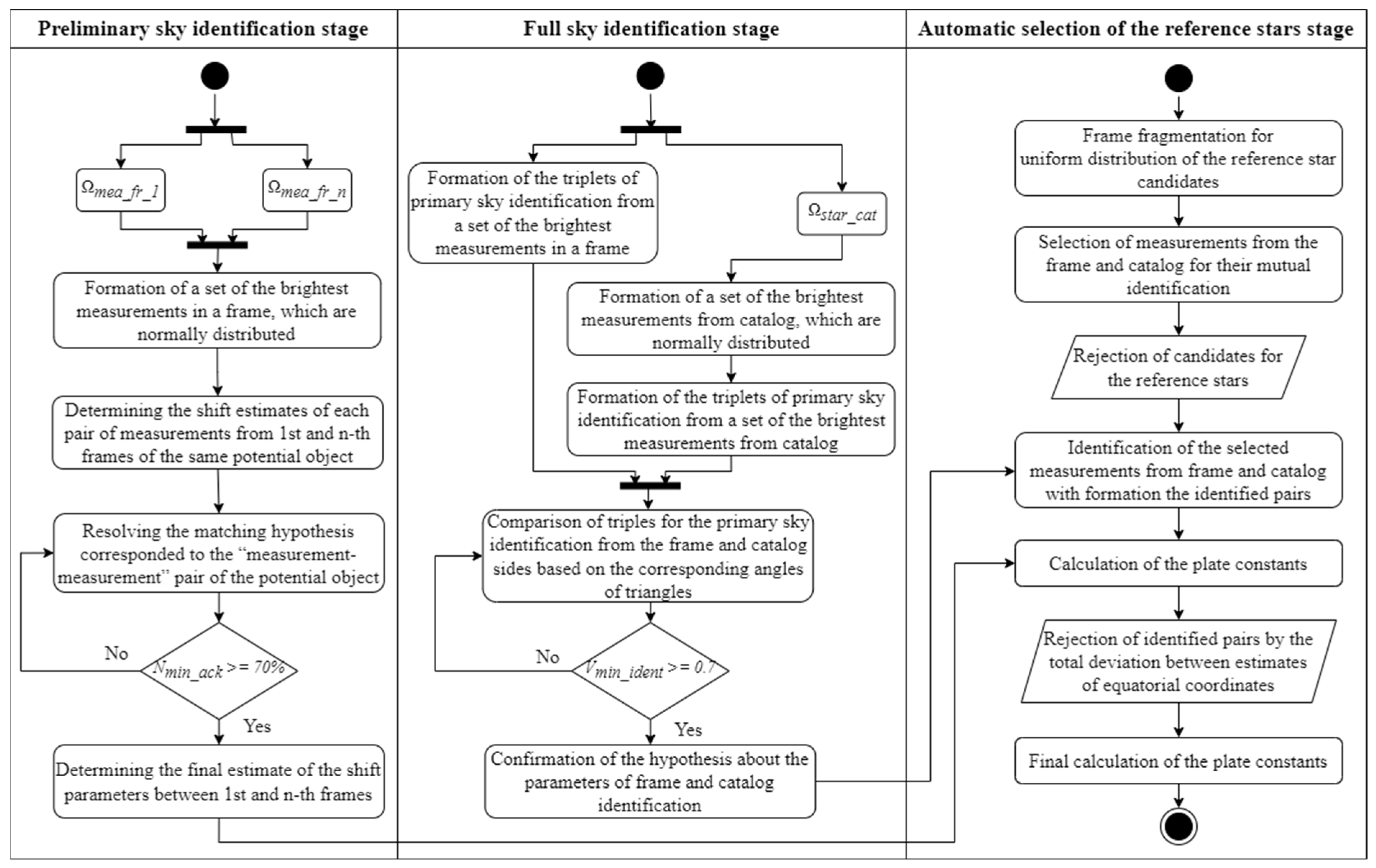
2.1. Preliminary Sky Identification

One of the cases of identification significant for practice is the case of mutual identification of frames of a series formed at approximately the same time on the same telescope by one CCD-camera without changing the angle of its rotation. For this, it is necessary to find the initial approximation of the parameters of pairwise correspondence (matching) between two sets of measurements formed in two frames and corresponding to the same region of the celestial sphere. The position of celestial objects in frames formed in this way, as a rule, differs only in the shift parameters (rotation parameters are near-zero [26], and the scale is unchanged from frame to frame). Shift parameters are common for all measurements of two frames and characterize the mutual arrangement of frames relative to each other on the celestial sphere, being the desired matching parameters between two sets of measurements.
With a preliminary sky identification of the measurements of digital frames of one series, it is advisable to avoid a global enumeration of matching measurements of these frames. To do this, it is necessary to consider the invariability of the shift parameters from pair to pair. In this case, it is possible to solve the problem of preliminary sky identification by putting forward (sorting out) hypotheses about the belonging of the measurements of different frames to the same object. Each such matching hypothesis corresponds to shift estimates conditional on the hypothesis of correspondence to the same object of the “measurement–measurement” pair for one measurement of each frame [27]:
Δ x i = x 1 ( i ) x 2 ( i ) ;
Δ y i = y 1 ( i ) y 2 ( i ) ,
where, x1(i), y1(i), x2(i), y2(i) are the coordinates of measurements of the same i-th object (estimates of the object’s coordinates) on the first and second identified frames in the coordinate system of the base frame of the series.
At the same time, the conditional estimate that corresponds to the hypothesis of a combination of pairs of measurements from different frames with the highest weight can be considered an unconditional estimate of the shift parameters between measurements of the position of the same object on different frames. As the weight of these hypotheses, the number of acknowledgments Nack was used. The number of acknowledgments is the number of acknowledgment circular areas (strobes) to which at least one measurement of another frame belongs (associated). The acknowledgment circular area (strobe) has a predetermined radius Rrej and center with the measurement coordinates of the first frame with the shift values (1), (2) added to them. In the general case, frames are quite rarefied and diverse in the sense that their individual parts are not like each other. Under this assumption, it is not possible to test all hypotheses about the combination of measurements of two frames. It is enough to find the first hypothesis, in which the number of acknowledgments will be higher than the predetermined allowable number of acknowledgments Nmin_ack (Figure 1).
One of the necessary requirements for the method of preliminary sky identification is its that it be resistant to various kinds of destabilizing factors [28]. First, the possible presence of a bright track of an artificial earth satellite in one of the frames. When a bright satellite [29] enters the frame, its image can illuminate the frame, forming many false measurements (Figure 2a). Second, the effect of charge flow when images of the brightest stars in frame lead to a decrease in the accuracy of the estimation of their position, which makes them undesirable candidates for reference stars (Figure 2b). To ensure the stability of results of the preliminary sky identification, the CCD-frame is divided into a predetermined number of regions of the same size Mreg × Mreg. From each such area, the same predetermined number of the brightest objects is selected Nmea_reg. Thus, the selected measurements will be evenly distributed over the frame, which will help to minimize the probability of errors in the preliminary sky identification. Such a selection of measurements will allow, for example, to exclude from consideration many bright false measurements caused by the charge flow of a large star or a bright satellite track.
Since the positions of objects in each frame are determined with errors, the parameters of frame shift relative to each other can be determined more precisely. This is achieved by averaging the shift parameters in each separate pair of object images in two frames:
Δ x = i = 1 N i d e n t Δ x i / N i d e n t ;
Δ y = i = 1 N i d e n t Δ y i / N i d e n t ,
where, N i d e n t is the pair number used in estimating frame shift parameters relative to each other.
Thus, the preliminary sky identification stage includes the following sequential steps.
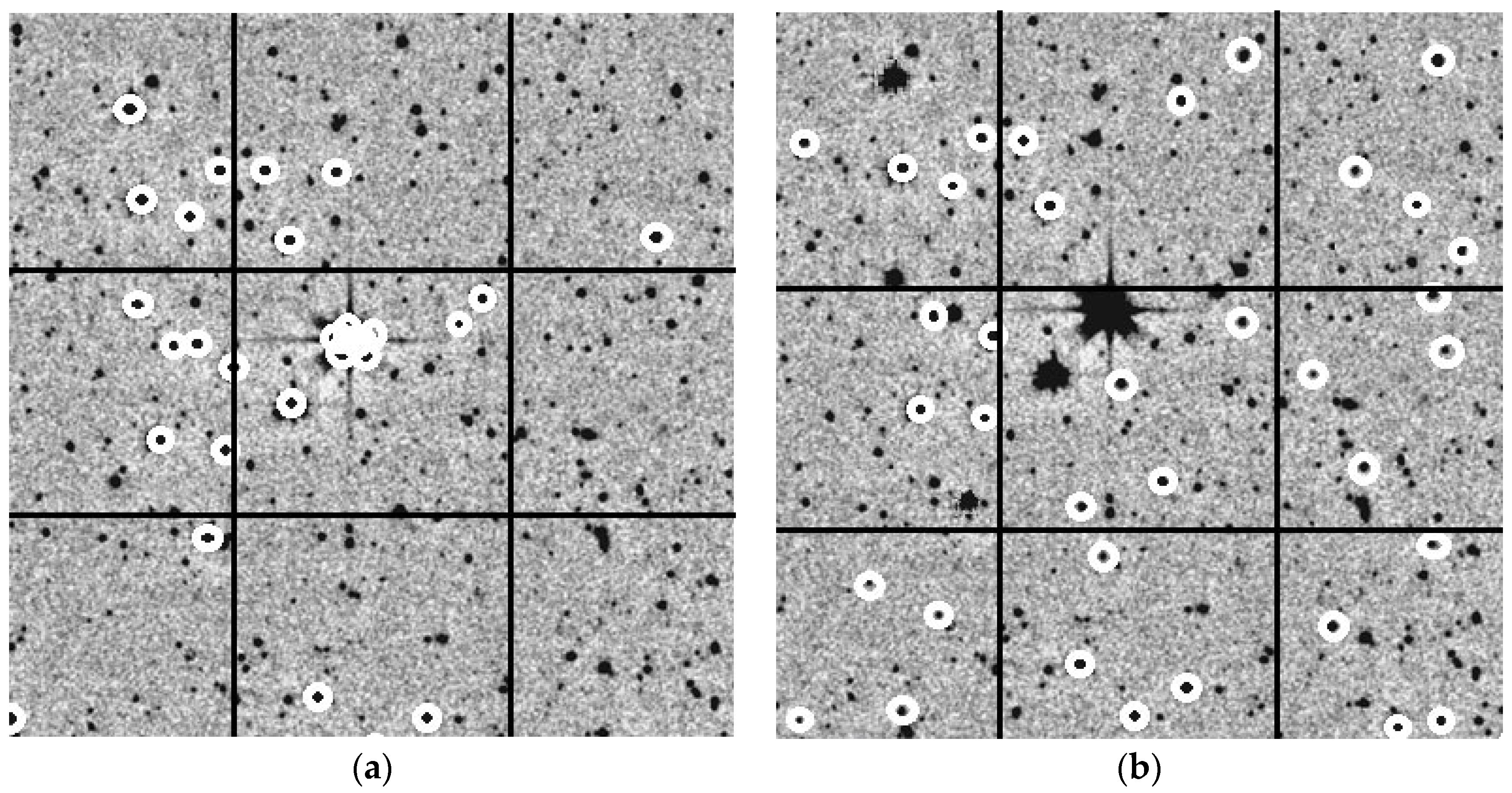
  • The frame is divided into a set of equal regions Mreg × Mreg. Sets of the brightest measurements in frame are formed based on an equal predetermined number Nmea_reg of measurements with the highest brightness estimates corresponding to the hypothetical objects selected from each region.
  • Selecting of the next measurement from a preselected set of the brightest measurements in the first frame. There should be no more than three such measurements. If, during the process, this step is reached for the fourth time (trying to select the fourth measurement), an emergency exit is performed with a message about identification failure. This is usually associated with large errors in estimating the anchoring coordinates of center in the identified frame.
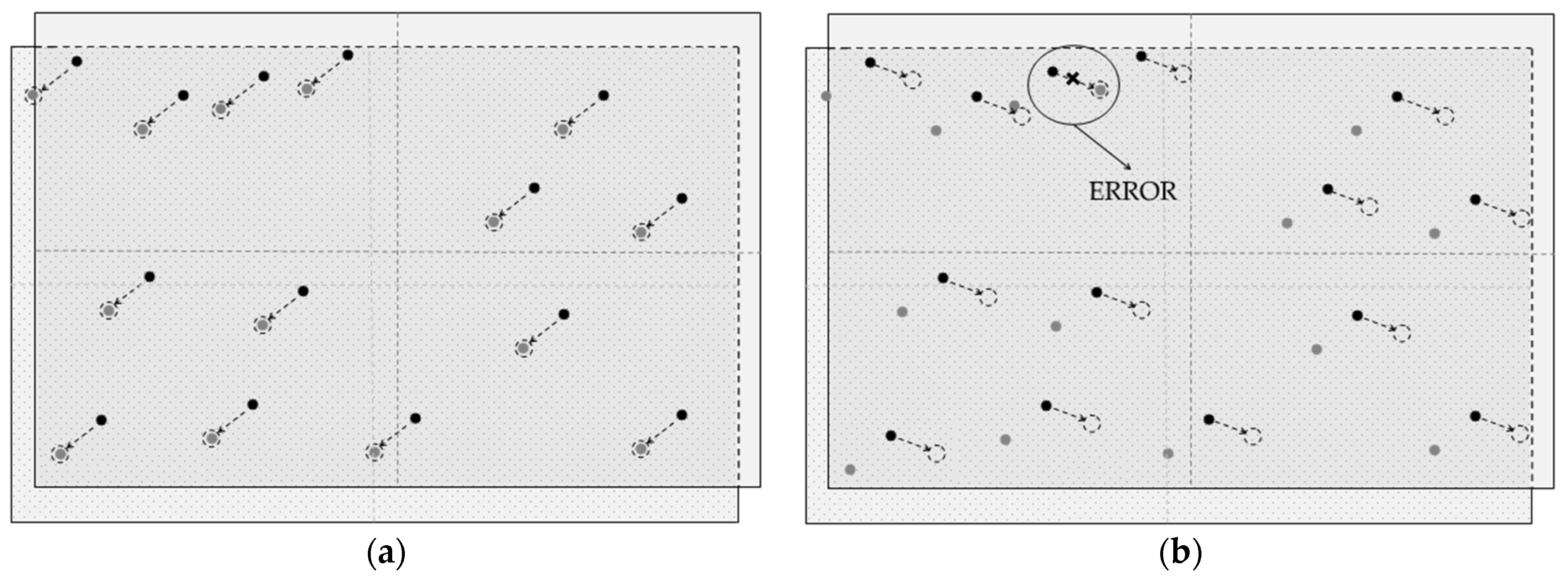
  • The investigated measurement of the first frame is put in correspondence with the next measurement of the second frame from a preselected set of measurements of the second frame (a cycle is organized according to the investigated measurements of the second frame). For this, a conditional estimate of the shift parameters is preliminarily calculated by the pair hypothesis, according to Equations (1) and (2).
  • For each selected pair (steps 2 and 3), the weight of the next hypothesis about the correspondence of pairs of measurements of the first and second frames (measurement of the frame and the star catalog) to the same object is estimated. For this, each measurement of the first frame is compared with each measurement of the second frame. Additionally, the shift parameters (1) and (2) are added to the measurement coordinates of the first frame. Based on the deviations between the measurements of the first and second frames, a fact that the measurements of the second frame fall into the acknowledgment area (strobe) is determined.
  • If a sufficient number of measurements of the second frame fell into the strobe, then it is considered that the hypothesis about the combination of pairs of measurements of the first and second frames is confirmed (go to step 6). If not, then the hypothesis about the shift parameters is considered false and a transition is made (to step 3) to the next measurement of the second frame. When the preselected set of measurements of the second frame is exhausted, a transition is made to the next measurement of the first frame (to step 2). If this set is also exhausted, a message is displayed about the impossibility of identifying the measurements of the first and second frames.
  • The final estimate of the shift parameters (3) and (4) is calculated.

2.2. Full Sky Identification

For the full sky identification with the star catalog, it is enough to have three points (stars) in a frame and their corresponding pairs in the star catalog. The coordinates of three stars include six parameters (x and y positional coordinates for each star). In this regard, a calculation of the plate constants by three points is the finite statistical method. It does not use the redundant data. Using such a method, it is impossible to eliminate or reduce the errors contained in the position estimates of stars in the catalog and frame. However, the finite method makes it possible to obtain an initial approximation with minimal computational costs.
The initial data for obtaining the plate linear constants by the finite statistical method are, on the one hand, the positions of three stars in the identified frame in the coordinate system (CS) of this CCD-frame (Figure 3). On the other hand, the ideal coordinates of the corresponding catalog stars. To obtain the ideal coordinates of the catalog stars from their equatorial coordinates, it is sufficient to have some approximation of the equatorial coordinates of the frame’s optical center. The points in Figure 3 correspond to three stars used, and their coordinates are indicated as A(x1, y1), B(x2, y2), C(x3, y3). The catalog equatorial coordinates of these stars correspond to the ideal coordinates A(ξ1, η1), B(ξ2, η2), C(ξ3, η3), respectively. The ideal coordinates of an object with its coordinates in the CS of the CCD-frame are related by the reduction equation [30]:
[ a 0 a 1 a 2 ] = [ 1 x 1 y 1 1 x 2 y 2 1 x 3 y 3 ] 1 [ ξ 1 ξ 2 ξ 3 ] ;
[ b 0 b 1 b 2 ] = [ 1 x 1 y 1 1 x 2 y 2 1 x 3 y 3 ] 1 [ η 1 η 2 η 3 ] .
An inverse reduction equation is also possible, which relates the coordinates of an object in the CS of the CCD-frame (x, y) with its ideal coordinates (ξ, η) [31]:
[ a 0 a 1 a 2 ] = [ 1 ξ 1 η 1 1 ξ 2 η 2 1 ξ 3 η 3 ] 1 [ x 1 x 2 x 3 ] ;
[ b 0 b 1 b 2 ] = [ 1 ξ 1 η 1 1 ξ 2 η 2 1 ξ 3 η 3 ] 1 [ y 1 y 2 y 3 ] .
To obtain the plate linear constants, it is necessary to have at least three stars in frame (three measurements) and their corresponding pairs—stars from the catalog. This matching can be called the primary identification triple. Obviously, this triple is not unique, but none of them are initially unknown. Each triple corresponds to the hypothesis of “primary identification” about the correspondence of frame and catalog triples. Selection of the first point of any triple is made without conditions. As such, all elements of the set of measurements Ωbl50 are used in turn. For the triple of measurements with coordinates (x1(k), y1(k)), (x2(k), y2(k)), (x3(k), y3(k)) in the CS of the CCD-frame to form a triangle, which covers a significant part of the frame, for the other two points of the triple, the following conditions are experimentally introduced. The second point of the triple must be no closer than k h of the frame’s angular size R C C D from the first one:
r ( 1 ) ( 2 ) = ( y 2 ( k ) y 1 ( k ) ) 2 + ( x 1 ( k ) x 2 ( k ) ) 2 0.5 k h ( R C C D ( x ) + R C C D ( y ) ) .
A condition for the third point of the triple is the selection of such a measurement in the frame, which corresponds to the point from which the perpendicular r t r i a n can be dropped to the straight line passing through the first and second points of the primary identification triple.
The equation for finding the perpendicular length r t r i a n is derived based on the definition of the modulus of the cross product of two vectors [32]. Using the property of the cross product of two vectors, it can be determined whether the vector drawn through the third point of the triple is perpendicular to these vectors. Additionally, the module of the cross product of the two corresponding vectors will be equal to the length of the perpendicular r t r i a n [33]:
r t r i a n = | x 1 ( k ) y 2 ( k ) x 2 ( k ) y 1 ( k ) | .
Thus, the sine and cosine of an angle γ 1 of the triple (Figure 3) can be found by equations:
sin γ 1 = ( x 2 ( k ) y 3 ( k ) y 2 ( k ) x 3 ( k ) x 2 ( k ) 2 + y 2 ( k ) 2 x 3 ( k ) 2 + y 3 ( k ) 2 ) ;
cos γ 1 = ( x 2 ( k ) x 3 ( k ) + y 2 ( k ) y 3 ( k ) x 2 ( k ) 2 + y 2 ( k ) 2 x 3 ( k ) 2 + y 3 ( k ) 2 ) .
With known sine and cosine of the angle, its unique finding is trivial. Similarly, to Equations (11) and (12), the values of the sines and cosines of the angles γ 2 and γ 3 can also be found using the following equations accordingly:
sin γ 2 = ( x 1 ( k ) y 3 ( k ) y 1 ( k ) x 3 ( k ) x 1 ( k ) 2 + y 1 ( k ) 1 2 x 3 ( k ) 2 + y 3 ( k ) 2 ) ;
cos γ 2 = ( x 1 ( k ) x 3 ( k ) + y 1 ( k ) y 3 ( k ) x 1 ( k ) 2 + y 1 ( k ) 2 x 3 ( k ) 2 + y 3 ( k ) 2 ) ;
sin γ 3 = ( x 1 ( k ) y 2 ( k ) y 1 ( k ) x 2 ( k ) x 1 ( k ) 2 + y 1 ( k ) 2 x 2 ( k ) 2 + y 2 ( k ) 2 ) ;
cos γ 3 = ( x 1 ( k ) x 2 ( k ) + y 1 ( k ) y 2 ( k ) x 1 ( k ) 2 + y 1 ( k ) 2 x 2 ( k ) 2 + y 2 ( k ) 2 ) .
According to [34], the CS of a CCD-frame is parallel to the plane of ideal astrophotography. Therefore, it is possible to use the plane of ideal astrophotography to calculate the angles of vertices of the triple of primary identification from the catalog side. For this, the tangential coordinates of stars of the used catalog are determined in the plane of ideal astrophotography with given equatorial coordinates ( α 0 , δ 0 ) of the optical center, according to the equations:
ξ j ( k ) = cos δ j ( k ) sin ( α j ( k ) α 0 ) cos δ 0 cos δ j ( k ) cos ( α j ( k ) α 0 ) + sin δ 0 sin δ j ( k ) ;
η j ( k ) = cos δ 0 cos ( α j ( k ) α 0 ) cos δ 0 cos δ j ( k ) cos ( α j ( k ) α 0 ) + sin δ 0 sin δ j ( k ) ,
where, α j ( k ) , δ j ( k ) are the angular coordinates of the j(k)-th object in the star catalog.
Based on the obtained tangential (ideal) coordinates, by analogy with Equations (11)–(16), the angles of the next triangle are determined, corresponding to the triple of primary identification from the catalog side.
Thus, the full sky identification stage includes the following sequential steps.
  • For a set of measurements of a CCD-frame, when forming the triplets of primary sky identification, the following sequence of operations is performed.
    • Formation of a set Ωbl50 of the brightest measurements in a CCD-frame, consisting of Nbl50 applicants when choosing triplets of primary identification. To ensure a stability of the identification results, the frame is divided into M r e g 2 parts. The specified number of frame measurements Nbl50 is divided by the number of frame fragments, and in each such fragment, the brightest frame measurements N b l 50 / M r e g 2 are selected.
    • Formation of an additional set Ωbl100 of the brightest measurements in a CCD-frame, consisting of Nbl100 elements evenly distributed in a frame (by analogy with 1a). The set Ωbl100 is used to confirm the hypotheses of primary identification (formation of a weight of the next hypothesis about the correspondence of triples in frame and the astronomical catalog).
  • For a set of measurements of the astronomical catalog, when forming the triplets of primary sky identification, the following sequence of operations is performed.
    • Formation of a set Ωstar100 of catalog measurements, considering the uniform distribution of stars in the investigated area of the sky.
    • Formation of an additional set Ωstar200 of catalog measurements, consisting of Nstar200 elements, which are used to confirm the hypotheses of primary identification.
  • Enumeration and confirmation of hypotheses of the primary sky identification.
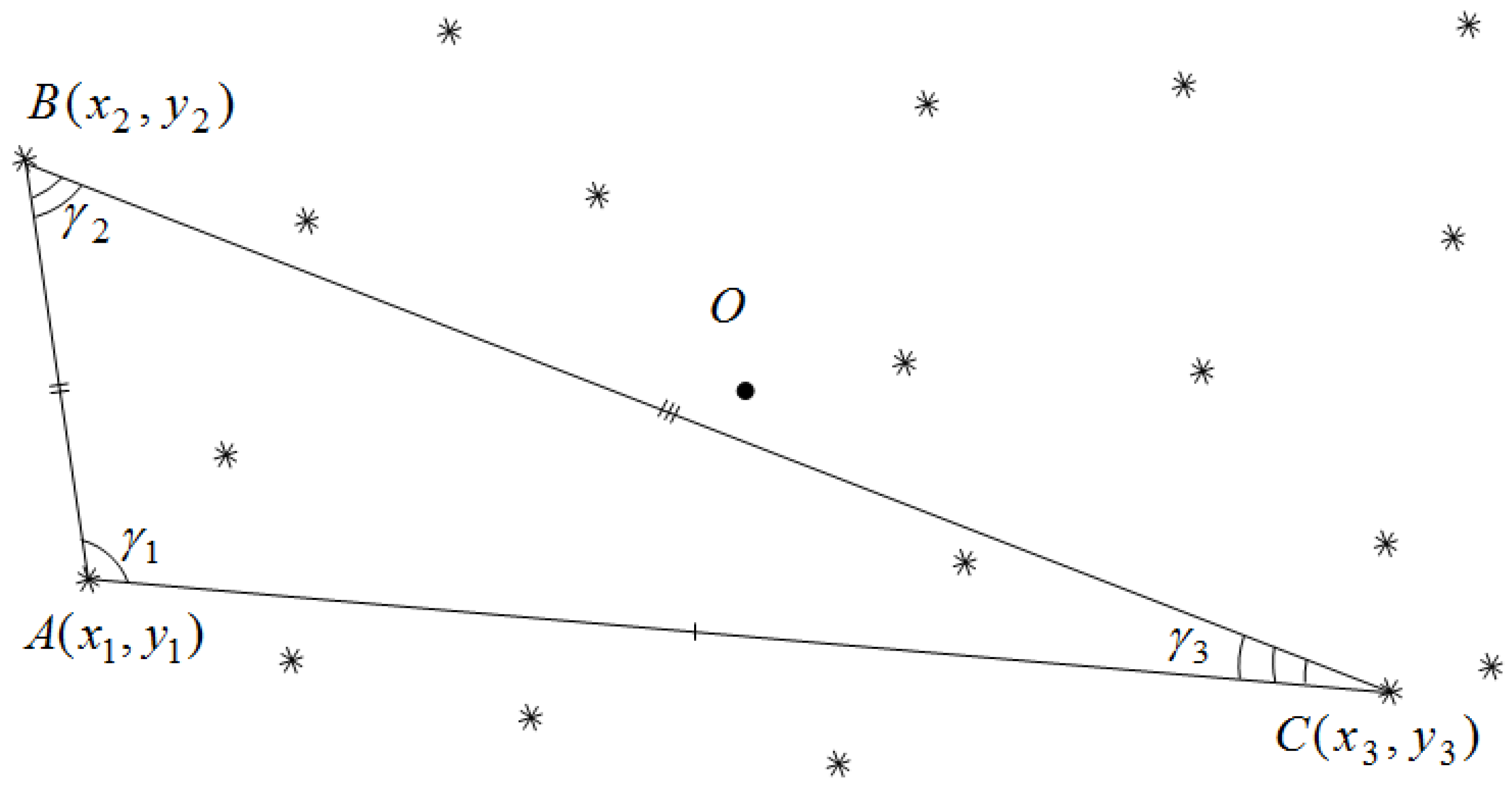
    • Enumerating the measurements of a set Ωbl50 as elements of triples of the primary sky identification. The measurements that make up the triple of the primary sky identification must satisfy the conditions (9) and (10).
    • Enumeration of a set Ωstar100 of catalog measurements as elements of triples of the primary sky identification from the astronomical catalog side.
    • Comparison of triples of measurements for the primary sky identification from the frame and catalog sides based on the corresponding angles of triangles, the values of which are calculated according to Equations (11)–(16).
    • Confirmation of the hypothesis about the parameters of frame and catalog identification, which corresponds to the considered triplets of the primary sky identification. The hypothesis is recognized as true if during the identification process of the sets Ωbl100 and Ωstar200 the formed admissible pairs exceed the predefined value vmin_ident. When the identification hypothesis is confirmed, further enumeration stops.

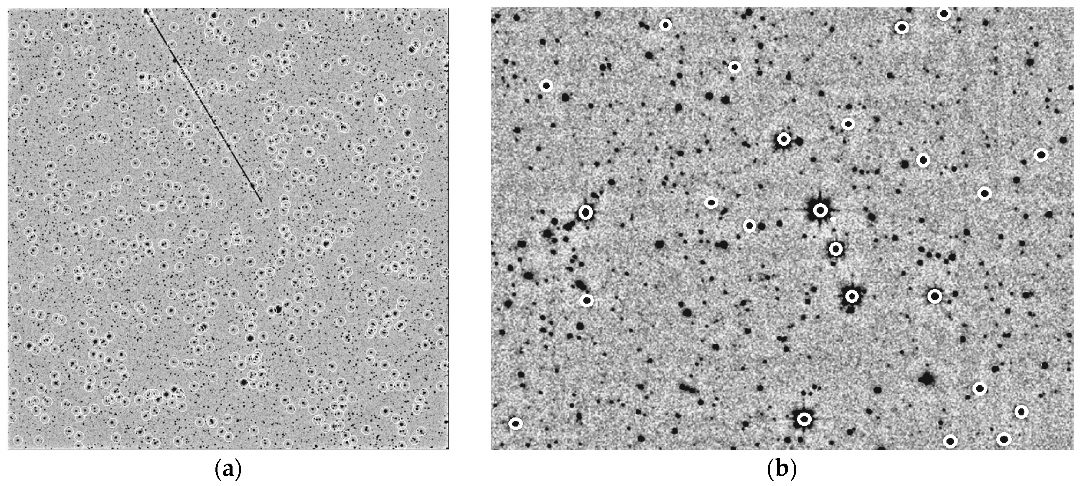
2.3. Automatic Selection of the Reference Stars

The methods for the preliminary (Section 2.1) and full (Section 2.2) sky identification make it possible to obtain the plate linear constants ( a p l 1 ; b p l 1 ; c p l 1 ) and ( a p l 2 ; b p l 2 ; c p l 2 ), which determine the relationship between the tangential (ideal) coordinate system and the coordinate system of a CCD-frame [35]:
{ ξ = a p l 1 x + b p l 1 y + c p l 1 ; η = a p l 2 x + b p l 2 y + c p l 2 .
The plate linear constant makes it possible to obtain estimates of the equatorial coordinates of objects in frame using the following equation [36]:
{ α = α 0 + arctg ( ξ cos δ 0 η sin δ 0 ) ; δ = arcsin η cos δ 0 + sin δ 0 1 + ξ 2 + η 2 ,
The uniform distribution of the identified pairs in a CCD-frame helps to avoid cases corresponding to the presence of a large number of the “bright” measurements/stars in one area of the frame (Figure 4).
To improve the accuracy of the plate constant estimates, after solving the identification task, a significant number of identified pairs are rejected. The decisive statistic for rejecting the identified pairs is the total deviation Δ α δ i j k between estimates of the equatorial coordinates in such a pair:
Δ α δ i j k = ( α c a t j ( k ) α m e a i n f r ( k ) ) 2 + ( δ c a t j ( k ) δ m e a i n f r ( k ) ) 2 .
The pair is rejected if the value Δ α δ i j k exceeds the critical value:
Δ α δ i j k > K r e j Δ ^ α δ ,
where, Δ ^ α δ is an average deviation modulus of the identified pair in the equatorial coordinates;
K r e j is a coefficient of the rule for rejecting pairs from a set of reference stars.
The average deviation modulus Δ ^ α δ is determined using the following equation:
Δ ^ α δ = 1 N c o u n t ( k = 1 N c o u n t ( α c a t j ( k ) α m e a i n f r ( k ) ) 2 + k = 1 N c o u n t ( δ c a t j ( k ) + δ m e a i n f r ( k ) ) 2 ) ,
where, N c o u n t is a count of the identified pairs;
α c a t j ( k ) , δ c a t j ( k ) are estimates of the right ascension and declination of an object from the j-th measurement in the astronomical catalog;
α m e a i n f r ( k ) , δ m e a i n f r ( k ) are estimates of the right ascension and declination of the i-th measurement in the nfr-th CCD-frame;
k is an index of the identified pair.
Thus, a stage for the automatic selection of the reference stars includes the following sequential steps.
  • Frame fragmentation for uniform distribution of the reference star candidates in a CCD-frame.
  • Selection of measurements from the frame and catalog for their mutual identification.
  • Rejection of candidates for the reference stars:
    • objects whose images do not have peaks;
    • catalog stars if they belong to the star clusters;
    • objects whose measurements have an intersection with the satellite track (Figure 2a);
    • catalog stars that are close to each other (Figure 2b).
  • Identification of the selected measurements from the frame and catalog with the formation of identified pairs.
  • Calculation of the plate constants (19) (at each next step with a higher degree model).
  • Rejection of identified pairs by the total deviation Δ α δ i j k (21) between estimates of equatorial coordinates in an identified pair (22).
  • Final calculation of the plate constants.
  • The UML-diagram of the developed mathematical methods for the sky identification is presented in Figure 5.

2.4. Accuracy Indicators of Estimates of the Angular Position and Brightness of the Reference Stars

The research of an accuracy indicators of estimates of the angular positions of reference stars in CCD-frames can be very useful for upgrading the software used by observatories equipped with the automated ground-based robotic telescopes, thereby increasing the accuracy of observations of the celestial objects.
Deviations between measurements from the frame and catalog of estimates of the equatorial coordinates (right ascension and declination) [37] and brightness [38] of the reference stars are determined using the following equations:
Δ α i = ( α j 1 ( i ) α j 2 ( i ) ) cos δ j 1 ( i ) ;
Δ δ i = δ j 1 ( i ) δ j 2 ( i ) ;
Δ m i = m j 1 ( i ) m j 2 ( i ) ,
where, i is a index of the identified pair;
α j 1 ( i ) , α j 2 ( i )   δ j 1 ( i ) , δ j 2 ( i ) are right ascension and declination of j1-th measurement from a frame and j2-th measurement from a catalog, forming the i-th identified pair;
m j 1 ( i ) , m j 2 ( i ) are brightness estimates of j1-th measurement from a frame and j2-th measurement from a catalog, forming the i-th identified pair;
j1 is an index of the measurement from a frame in the internal numeration;
j2 is an index of the measurement from a catalog in the internal numeration.
Estimation of the mean deviation (mathematical expectation of deviations) of estimates of the equatorial coordinates (24)−(25) and brightness (26) of the reference stars are determined using the following equations [39]:
Δ ^ α = i = 1 N mea Δ a i / N mea ;
Δ ^ δ = i = 1 N mea Δ δ i / N mea ;
Δ ^ m = i = 1 N mea Δ m i / N mea ,
where, Nmea is the number of measurements used to analyze the accuracy of estimates of the angular position of objects.
Estimation of the standard deviation of estimates of the coordinates by right ascension and declination, as well as brightness of the reference stars, are determined using the following equations [40]:
σ ^ α = i = 1 N mea ( Δ α i Δ ^ α ) 2 / ( N mea 1 ) ;
σ ^ δ = i = 1 N mea ( Δ δ i Δ ^ δ ) 2 / ( N mea 1 ) ;
σ ^ m = i = 1 N mea ( Δ m i Δ ^ m ) 2 / ( N mea 1 ) ,

3. Results

3.1. Real Astronomical Data Sources

All studies were carried out using the CCD-frames formed at the different times of year, on different telescopes and CCD-cameras. Below is a list of these observatories and some technical characteristics of the telescopes and CCD-cameras used. All such observatories have the special code [41] from the Minor Planet Center (MPC) from the International Astronomical Union (IAU) [42].
The ISON-NM observatory (MPC code “H15”) is located on Mount Joy (Mayhill, NM, USA). This observatory uses a 40-cm SANTEL-400AN telescope as an observation tool with focal length f = 1197.37 mm and CCD-camera FLI ML09000-65 (3056 × 3056 pixels, pixel size is 12 microns) [43]. The exposure time of the studied frames was 150 s.
The Cerro Tololo observatory (MPC code “807”) is located 80 km from the city of La Serena (Chile). La Silla Observatory uses a 46-cm PROMPT-8 telescope with focal length f = 4201.035 mm and CCD-camera E2V (2048 × 2048 pixels, pixel size is 13.5 microns) [44]. The exposure time of the studied frames was 10 s.
The Vihorlat Observatory in Humenné (MPC code “Humenne”) is in a remote branch of the Astronomical Observatory on the Kolonitsky saddle between the Vihorlat and Bukovske Vrhi mountain ranges, 38 km from the city of Humenne (Slovakia). The observatory uses the Vihorlat National Telescope (VNT), a Cassegrain telescope with a main mirror diameter of 1 m with focal length f = 8958.50 mm and CCD-camera FLI PL1001E (512 × 512 pixels, pixel size is 4.8 microns) [15]. The exposure time of the studied frames was 60 s.
The Mayaki observing station (MPC code “583”) is a section of the Astronomical Observatory Research Institute of I. I. Mechnikov Odessa National University. The station uses the AZT-3 reflector telescope with a main mirror diameter of 0.48 m with focal length f = 2025 mm and CCD-camera Sony ICX429ALL (795 × 596 pixels, pixel size is 12 microns) [37]. The exposure time of the studied frames was 150 s.

3.2. Reference Data Sources

To calculate the measurement deviations, it is necessary to obtain the reference coordinate values of the reference stars.
As reference values of the angular positions of the reference stars, we used data from the UCAC 4.0 astrometric catalog [45]. Its average density is over 2000 stars per square degree. The catalog contains data on more than 113 million stars and covers the sky in brightness up to 16 of magnitude. The position error of any object does not exceed 20 arc milliseconds. The error of the proper motion of each object is from 2 to 8 arc milliseconds per year.
As reference values of a brightness of the reference stars, we used data from the USNO B1.0 photometric catalog [46]. The catalog contains estimates of the angular positions and brightness of more than one billion objects, which were formed based on 3.6 billion individual measurements.

3.3. Accuracy of the Developed Mathematical Methods for the Sky Identification

During research the following statistical accuracy indicators [47] of estimates of the angular position and brightness of the reference stars were used:
  • Mean deviation (27)–(29);
  • Max. deviation module;
  • Min. deviation module;
  • Standard deviation of estimates (30)–(32).
The main parameters of deviations of the angular positions and brightness of the observed reference stars are presented in Table 1. In total, 30,391 measurements were processed under research.
Figure 6 shows histograms of the distributions of deviations of the equatorial coordinates in right ascension (RA) and declination (DE) of the reference stars. The x-axis shows the deviation values for the appropriate equatorial coordinate (RA/DE), and the y-axis shows the number of measurements.
All specific parameters for the mathematical methods and their values, which were used under research, are described in Appendix A.

3.4. Implementation in the CoLiTec Software

The developed mathematical methods were successfully implemented in the Collection Light Technology (CoLiTec) software [48]. More details about the architecture are described in this paper [49]. It also implements modern data mining [50] and knowledge discovery in database [51] approaches.
The special module for the identification of measurements was created as a part of the CoLiTec software (Figure 7). It implements the developed mathematical methods. Its main goal is to perform accurate sky identification based on the measurements received from the module for intraframe processing and measurements of stars from the stellar catalogue.
The input for the module for the identification of measurement is a set of raw measurements, which includes estimates of the positional coordinates and the brightness of each detected but not identified object in a series of frames.
The output of such a module is a set of measurements related to the already identified real known objects (stars), including their positional coordinates and the brightness of in each frame in the series. Additionally, the celestial coordinates of each frame’s center are determined, which makes it possible to navigate the automated mounts of the robotic telescopes using the special celestial coordinates.
Using the CoLiTec software, more than 1600 small solar system objects were discovered. It has been used in more than 700,000 observations and successful sky identification, during which five comets were discovered.
The accuracy of processing results of the CoLiTec software shows benefits and low standard deviation of the sky identification in the case of low signal to noise ratios. That is why the CoLiTec software was recommended for all members of the Gaia-FUN-SSO network [52] as a tool for the faint astronomical object detection in a series of frames. Additionally, the CoLiTec project belongs to the Ukrainian Virtual Observatory (UkrVO) project [53].

4. Discussion

During the preliminary sky identification stage, the initial approximation of the parameters of pairwise correspondence (pairing) between two sets of measurements formed in the two nearest frames in a series and corresponding to the same region of the celestial sphere is performed. With its help, the shift estimates of each pair of measurements from the first and n-th frames of the same potential object were determined. After this, the matching hypothesis corresponded to the “measurement–measurement” pair of the potential object was resolved. This stage helps to determine the final estimates of the shift parameters between each frame in an input series of frames.
The full sky identification stage is used to find the initial approximation when identifying frame measurements with catalog stars under conditions of significant uncertainty in the identification parameters. With uncertainty about all six identification parameters, namely, about the parameters of the frame shift, camera rotation angle, and pixel scale, as an initial approximation, it is necessary to obtain six parameters of plate linear constants. For this, it is enough to have three points (stars in a CCD-frame), which make up a triangle of the primary identification. Proceeding from this, the stars are sorted as the vertices of the identification triangles in a CCD-frame and in the astronomical catalog. Each such pair of triangles corresponds to the “primary identification” hypothesis, within which, conditional estimates of the identification parameters are determined. After this, the comparison of triples for the primary sky identification from the frame and catalog sides based on the corresponding angles of triangles is performed. This stage helps to confirm the hypothesis about the parameters of frame and catalog identification.
The preliminary and full sky identification stages provide the necessary information (shift estimates, parameters of frame and catalog identification, and others) for the next stage. The automatic selection of the reference stars stage is based on using the cubic reduction model (plate constants) that defines the relationship between the ideal (tangential) and equatorial coordinate systems and a small number of the identified “measurement–star” pairs.
The main steps from this last stage are the rejection of candidates for the reference stars from the astronomical catalog as well as the rejection of identified pairs by the total deviation between estimates of equatorial coordinates. This allows for a uniform distribution of the reference points with almost the same magnitude and improving the set of measurements and identified pairs without large outliers in accuracy.
That is why the developed methods are resistant to various types of artifacts and errors that occur during the formation of a digital image. This is one of the main advantages of the developed computational mathematical methods.
Additionally, as a result of the research, the number of parameters of the developed method used to maximize the accuracy indicators for determining the angular position of objects was significantly reduced, and the range of their allowable values was significantly narrowed.
As shown in Table 1, a total of 30,391 measurements were processed under research and the main parameters of deviations of the angular positions and brightness of the observed reference stars were calculated. As results showed, the mean deviations of the angular coordinates (RA and DE) are 0.003 and 0.002, accordingly. If the rejection threshold is increased to reject 10% of bad measurements, the mean deviations of both coordinates become 0.001 arc seconds or 1 arc millisecond. In comparison with the known position error of any astronomical object from catalog, which does not exceed 20 arc milliseconds, this is a very high accuracy. Additionally, in comparison with an error of the proper motion of each object, which is from 2 to 8 arc milliseconds per year, this is a very exponential accuracy.
Further research is planned to adapt the developed method for the multi-robot systems based on real-time [54]. To obtain the best accuracy indicators of determining the angular position of objects, research of the influence on the accuracy of some parameters of the method is planned. They are the maximum allowable distance between neighboring stars of a group of objects rstar_group, the number of fragments into which the frame is divided along each coordinate when selecting the reference stars Mreg, and the maximum allowable distance between neighboring measurements of a group of pixels rmea_group.
To prepare the wider comparison statistics, a different approach will also be applied as the Wavelet [55] and time-series analysis [56], as well as computer vision techniques [57] and machine learning [58]. However, for the last one, the set of measurements should be extremely large for the training model preparation; therefore, the collection of such test data requires a wide time frame.

5. Conclusions

Special computational mathematical methods were developed for the full astrometric calibration process. They include the preliminary and full sky identification in the CCD-frames in a series with the further automatic selection of reference stars from the international star catalogs/databases [18].
The developed methods were tested using real astronomical data from the different sources and observational conditions of telescopes. The main accuracy indicators, such as mean, minimal, maximum, standard deviation, were calculated. The results showed a high accuracy in comparison with the known position error or proper motion error of any astronomical object. The developed methods are resistant to various types of artifacts and errors that occur during the formation of a digital image because of the list of rejection rules for the raw measurements as well as reference star selection rules. During the research, a lot of processing parameters were carefully empirically selected for the best accuracy.
Limitations of the developed methods are only related to the processing time and required calibration stage for the automated mount of the robotic telescope. Such a calibration stage includes the preparation of a small series of at least three frames and processing the received measurements by the developed methods to get the accurate celestial coordinates of the FOV center for the further automated navigation. Additionally, the international star catalogs/databases can be used in two modes: online, using the Internet (if connection is available), or offline, using the downloaded catalogs on hardware.
The developed methods were implemented into the CoLiTec software [20] in the module for measurement identification. The processing results of the CoLiTec software, with the help of successful sky identification, is presented in Table 2.
The accuracy of processing results of the CoLiTec software shows benefits, even in case of low signal-to-noise ratios. Additionally, the CoLiTec software was recommended for all members of the Gaia-FUN-SSO network [52] as a tool for moving faint object detection, including sky identification at the pre-processing stage.

Author Contributions

Conceptualization, V.S. and S.K.; methodology, V.S.; software, O.B.; validation, V.S. and I.T.; formal analysis, V.S.; investigation, I.T. and T.T.; resources, O.B.; data curation, O.B.; writing—original draft preparation, S.K.; writing—review and editing, S.K.; visualization, T.T.; supervision, V.S.; project administration, V.S. All authors have read and agreed to the published version of the manuscript.

Funding

This research received no external funding.

Informed Consent Statement

Informed consent was obtained from all subjects involved in the study.

Data Availability Statement

Data sharing not applicable.

Conflicts of Interest

The authors declare no conflict of interest.

Appendix A

The appendix contain all specific parameters for the developed mathematical methods and their values, which were used under research. They are:
  • Radius Rrej of the acknowledgment circular area (strobe) is Rrej = 20 pixels;
  • Minimum allowable number of acknowledgments Nmin_ack = 70%;
  • Number of equal regions Mreg×Mreg, on which frame is divided into is Mreg×Mreg = 4×4;
  • Number Nmea_reg of measurements with the highest brightness estimates in frame is N m e a _ r e g = N m e a / M r e g 2 = 3 ;
  • Number Nbl50 of measurements (candidates) in frame for the role of elements of triplets (vertices of triangles) of the primary sky identification is Nbl50 = 50;
  • Number Nbl100 of elements of the set Ωbl100 of measurements in frame used to confirm the hypotheses of the primary sky identification is Nbl100 = 100;
  • Ratio of the number of elements of the sets Ωbl100 and Ωbl50 of measurements in frame was assumed to be equal to kblob = Nbl100/Nbl50 = 2;
  • Number of regions Mreg, on which frame is divided into is Mreg = 4;
  • Number Nstar100 of stars (candidates) in astrometric catalog for the role of elements of triplets (vertices of triangles) of the primary sky identification is Nstart100 = 100;
  • Number Nstar200 of stars of the set Ωstar200 of measurements in astrometric catalog used to confirm the hypotheses of the primary sky identification is Nstar200 = 200;
  • Ratio of the number of elements of the sets Ωstar200 and Ωstar100 of measurements in frame was assumed to be equal to kstar = Nstar200/Nstar100 = 2;
  • Maximum allowable minimal distance between the second and first points of the triple of the primary sky identification, expressed in the angular measurements of a CCD-frame is kh = 0.1;
  • Under the condition of a rectangular (not square) frame, to determine the minimum distance between the second and first points of the triple, the value kh is multiplied by the average value of the frame size for both coordinates;
  • Maximum allowable deviation of values of the corresponding angles of the triangles (from a CCD-frame and the astrometric catalog sides) of the primary sky identification is Δᵞ = 60′.
  • Limiting maximum value of the distance between the elements of an identified pair, at which it is considered valid is Δrident = 10 pixels;
  • Minimum allowable ratio of the number of allowed pairs to the set Ωbl100 size is vmin_ident = 0.7.

References

  1. Ackermann, M.; Ajello, M.; Albert, A.; Allafort, A.; Atwood, W.B.; Axelsson, M.; Baldini, L.; Ballet, J.; Barbiellini, G.; Bastieri, D.; et al. The Fermi large area telescope on orbit: Event classification, instrument response functions, and calibration. Astrophys. J. Suppl. Ser. 2012, 203, 4. [Google Scholar] [CrossRef]
  2. Savanevych, V.E.; Briukhovetskyi, A.B.; Ivashchenko, Y.N.; Vavilova, I.B.; Bezkrovniy, M.M.; Dikov, E.N.; Vlasenko, V.P.; Sokovikova, N.S.; Movsesian, I.S.; Dikhtyar, N.Y.; et al. Comparative analysis of the positional accuracy of CCD measurements of small bodies in the solar system software CoLiTec and Astrometrica. Kinemat. Phys. Celest. Bodies 2015, 31, 302–313. [Google Scholar] [CrossRef]
  3. Schroeder, D.J. Astronomical Optics; Elsevier: Amsterdam, The Netherlands, 1999. [Google Scholar]
  4. Smith, G. Nobel Lecture: The invention and early history of the CCD. Rev. Mod. Phys. 2010, 82, 2307–2312. [Google Scholar] [CrossRef]
  5. Adam, G.K.; Kontaxis, P.A.; Doulos, L.T.; Madias, E.-N.D.; Bouroussis, C.A.; Topalis, F.V. Embedded microcontroller with a CCD camera as a digital lighting control system. Electronics 2019, 8, 33. [Google Scholar] [CrossRef]
  6. Mykhailova, L. Method of maximum likelihood estimation of compact group objects location on CCD-frame. East.-Eur. J. Enterp. Technol. 2014, 5, 16–22. [Google Scholar]
  7. Savanevych, V.; Briukhovetskyi, O.B.; Sokovikova, N.S.; Bezkrovny, M.M.; Vavilova, I.B.; Ivashchenko, Y.M.; Elenin, L.V.; Khlamov, S.; Movsesian, I.S.; Dashkova, A.M.; et al. A new method based on the subpixel Gaussian model for accurate estimation of asteroid coordinates. Mon. Not. R. Astron. Soc. 2015, 451, 3287–3298. [Google Scholar] [CrossRef]
  8. Hale, S.J.; Chaplin, W.J.; Davies, G.R.; Elsworth, Y.P. A next generation upgraded observing platform for the automated Birmingham Solar Oscillations Network (BiSON). In Software and Cyberinfrastructure for Astronomy VI; SPIE: Bellingham, WA, USA, 2020; Volume 11452. [Google Scholar]
  9. Singha, J.; Basu, A.; Krishnakumar, M.A.; Joshi, B.C.; Arumugam, P. A real-time automated glitch detection pipeline at Ooty Radio Telescope. Mon. Not. R. Astron. Soc. 2021, 505, 5488–5496. [Google Scholar] [CrossRef]
  10. Roberts, W.T.; Antsos, D.; Croonquist, A.; Piazzolla, S.; Roberts, L.C.; Garkanian, V.; Trinh, T.; Wright, M.W.; Rogalin, R.; Wu, J.; et al. Overview of Ground Station 1 of the NASA space communications and navigation program. Free. Space Laser Commun. Atmos. Propag. XXVIII 2016, 9739, 97390B. [Google Scholar]
  11. Tarasov, S.M. A Study on the Effect Produced by Instrumental Error of Automated Astronomical System on Landmark Azimuth Accuracy. Gyroscopy Navig. 2021, 12, 178–185. [Google Scholar] [CrossRef]
  12. Gayvoronsky, S.V.; Kuzmina, N.V.; Tsodokova, V.V. High-accuracy determination of the Earth’s gravitational field parameters using automated zenith telescope. In Proceedings of the 24th Saint Petersburg International Conference on Integrated Navigation Systems (ICINS), Saint Petersburg, Russia, 29–31 May 2017; pp. 1–4. [Google Scholar]
  13. Lösler, M.; Eschelbach, C.; Riepl, S. A modified approach for automated reference point determination of SLR and VLBI telescopes: First investigations at Satellite Observing System Wettzell. Tech. Mess. 2018, 85, 616–626. [Google Scholar] [CrossRef]
  14. Hampson, K.M.; Gooding, D.; Cole, R.; Booth, M.J. High precision automated alignment procedure for two-mirror telescopes. Appl. Opt. 2019, 58, 7388–7391. [Google Scholar] [CrossRef] [PubMed]
  15. Parimucha, Š.; Savanevych, V.E.; Briukhovetskyi, O.B.; Khlamov, S.V.; Pohorelov, A.V.; Vlasenko, V.P.; Dubovský, P.A.; Kudzej, I. CoLiTecVS—A new tool for an automated reduction of photometric observations. Contrib. Astron. Obs. Skaln. Pleso 2019, 49, 151–153. [Google Scholar]
  16. Savanevych, V.; Akhmetov, V.; Khlamov, S.; Dikov, E.; Briukhovetskyi, A.; Vlasenko, V.; Khramtsov, V.; Movsesian, I. Selection of the reference stars for astrometric reduction of CCD-frames. Adv. Intell. Syst. Comput. 2020, 1080, 881–895. [Google Scholar]
  17. Akhmetov, V.; Khlamov, S.; Dmytrenko, A. Fast coordinate cross-match tool for large astronomical catalogue. Adv. Intell. Syst. Comput. 2019, 871, 3–16. [Google Scholar]
  18. Vavilova, I.; Pakuliak, L.; Babyk, I.; Elyiv, A.; Dobrycheva, D.; Melnyk, O. Surveys, catalogues, databases, and archives of astronomical data. In Knowledge Discovery in Big Data from Astronomy and Earth Observation; Astrogeoinformatics; Elsevier: Amsterdam, The Netherlands, 2020; pp. 57–102. [Google Scholar]
  19. Akhmetov, V.; Khlamov, S.; Khramtsov, V.; Dmytrenko, A. Astrometric reduction of the wide-field images. Adv. Intell. Syst. Comput. 2020, 1080, 896–909. [Google Scholar]
  20. Khlamov, S.; Savanevych, V. Big astronomical datasets and discovery of new celestial bodies in the Solar System in automated mode by the CoLiTec software. In Knowledge Discovery in Big Data from Astronomy and Earth Observation; Astrogeoinformatics; Elsevier: Amsterdam, The Netherlands, 2020; pp. 331–345. [Google Scholar]
  21. Khlamov, S.; Savanevych, V.; Briukhovetskyi, O.; Oryshych, S. Development of computational method for detection of the object’s near-zero apparent motion on the series of CCD–frames. East. Eur. J. Enterp. Technol. 2016, 2, 41–48. [Google Scholar] [CrossRef]
  22. Tantsiura, A. Evaluation of the potential accuracy of correlation extreme navigation systems of low-altitude mobile robots. Int. J. Adv. Trends Comput. Sci. Eng. 2019, 8, 2161–2166. [Google Scholar] [CrossRef]
  23. Savanevych, V.; Khlamov, S.; Akhmetov, V.; Briukhovetskyi, A.; Vlasenko, V.; Dikov, E.; Kudzej, I.; Dubovsky, P.; Mkrtichian, D.; Tabakova, I.; et al. CoLiTecVS software for the automated reduction of photometric observations in CCD-frames. Astron. Comput. 2022, 40, 15. [Google Scholar] [CrossRef]
  24. Savanevych, V.; Khlamov, S.; Vlasenko, V.; Deineko, Z.; Briukhovetskyi, O.; Tabakova, I.; Trunova, T. Formation of a typical form of an object image in a series of digital frames. East.-Eur. J. Enterp. Technol. 2022, 6, 51–59. [Google Scholar]
  25. Yeromina, N.; Tarshyn, V.; Petrov, S.; Samoylenko, V.; Tabakova, I.; Dmitriiev, O.; Surkova, K.; Danylko, O.; Kushnierova, N.; Soroka, M.; et al. Method of reference image selection to provide high-speed aircraft navigation under conditions of rapid change of flight trajectory. Int. J. Adv. Technol. Eng. Explor. 2021, 8, 1621–1638. [Google Scholar]
  26. Khlamov, S.; Savanevych, V.; Briukhovetskyi, O.; Pohorelov, A. CoLiTec software-detection of the near-zero apparent motion. Proc. Int. Astron. Union 2016, 12, 349–352. [Google Scholar] [CrossRef]
  27. Akhmetov, V.; Khlamov, S.; Tabakova, I.; Hernandez, W.; Hipolito, J.I.N.; Fedorov, P. New approach for pixelization of big astronomical data for machine vision purpose. In Proceedings of the IEEE International Symposium on Industrial Electronics, Vancouver, BC, Canada, 12–14 June 2019; pp. 1706–1710. [Google Scholar]
  28. Zhilenkov, A.; Chernyi, S.; Sokolov, S.; Nyrkov, A. Algorithmic approach of destabilizing factors of improving the technical systems efficiency. Vibroeng. Procedia 2017, 13, 261–265. [Google Scholar] [CrossRef]
  29. Akhmetov, V.; Khlamov, S.; Savanevych, V.; Dikov, E. Cloud computing analysis of Indian ASAT test on March 27, 2019. In Proceedings of the IEEE International Scientific-Practical Conference: Problems of Infocommunications Science and Technology, Kyiv, Ukraine, 8–11 October 2019; pp. 315–318. [Google Scholar]
  30. Branham, R.L., Jr. Astronomical data reduction with total least squares. New Astron. Rev. 2001, 45, 649–661. [Google Scholar] [CrossRef]
  31. Burger, W.; Burge, M. Principles of Digital Image Processing: Fundamental Techniques; Springer: New York, NY, USA, 2009. [Google Scholar]
  32. Sommerville, D.M.Y. Analytical Geometry of Three Dimensions; Cambridge University Press: Cambridge, UK, 2016. [Google Scholar]
  33. Fischer, G. Complex Analytic Geometry; Springer: New York, NY, USA, 2006; Volume 538. [Google Scholar]
  34. Legault, T. Astrophotography; Rocky Nook, Inc.: San Rafael, CA, USA, 2014. [Google Scholar]
  35. Khlamov, S.; Vlasenko, V.; Savanevych, V.; Briukhovetskyi, O.; Trunova, T.; Chelombitko, V.; Tabakova, I. Development of computational method for matched filtration with analytic profile of the blurred digital image. East.-Eur. J. Enterp. Technol. 2022, 5, 24–32. [Google Scholar]
  36. Gonzalez, R.; Woods, R. Digital Image Processing, 4th ed.; Pearson: New York, NY, USA, 2018. [Google Scholar]
  37. Kwiatkowski, T.; Koleńczuk, P.; Kryszczyńska, A.; Oszkiewicz, D.; Kamiński, K.; Kamińska, M.K.; Troianskyi, V.; Skiff, B.; Moskowitz, N.; Kashuba, V.; et al. Photometry and model of near-Earth asteroid 2021 DW1 from one apparition. Astron. Astrophys. 2021, 656, A126. [Google Scholar] [CrossRef]
  38. Starck, J.-L.; Murtagh, F. Astronomical image and data analysis. In Astronomy and Astrophysics Library, 2nd ed.; Springer: Berlin/Heidelberg, Germany, 2007. [Google Scholar]
  39. Steger, C.; Ulrich, M.; Wiedemann, C. Machine Vision Algorithms and Applications; John Wiley & Sons: Hoboken, NJ, USA, 2018. [Google Scholar]
  40. Lehmann, E.; Romano, J.; Casella, G. Testing Statistical Hypotheses; Springer: New York, NY, USA, 2005; Volume 3. [Google Scholar]
  41. The Minor Planet Center (MPC) of the International Astronomical Union. Available online: https://minorplanetcenter.net (accessed on 1 March 2023).
  42. List of Observatory Codes: IAU Minor Planet Center. Available online: https://minorplanetcenter.net/iau/lists/ObsCodesF.html (accessed on 1 March 2023).
  43. Molotov, I.; Agapov, V.; Kouprianov, V.; Titenko, V.; Rumyantsev, V.; Biryukov, V.; Borisov, G.; Burtsev, Y.; Khutorovsky, Z.; Kornienko, G.; et al. ISON worldwide scientific optical network. In Proceedings of the Fifth European Conference on Space Debris, Darmstadt, Germany, 30 March–2 April 2009; ESA: Paris, France, 2009; Volume 7, p. SP-672. [Google Scholar]
  44. Li, T.; DePoy, D.L.; Marshall, J.L.; Nagasawa, D.Q.; Carona, D.W.; Boada, S. Monitoring the atmospheric throughput at Cerro Tololo Inter-American Observatory with aTmCam. Ground-Based Airborne Instrum. Astron. V 2014, 9147, 2194–2205. [Google Scholar]
  45. Zacharias, N.; Finch, C.T.; Girard, T.M.; Henden, A.; Bartlett, J.L.; Monet, D.G.; Zacharias, M.I. The fourth US naval observatory CCD astrograph catalog (UCAC4). Astron. J. 2013, 145, 44. [Google Scholar] [CrossRef]
  46. Luo, X.; Gu, S.; Xiang, Y.; Wang, X.; Yeung, B.; Ng, E.; Bai, J.; Fan, Y.; Xu, F.; Cao, D.; et al. Active longitudes and starspot evolution of the young rapidly rotating star USNO-B1.0 1388−0463685 discovered in the Yunnan–Hong Kong survey. Mon. Not. R. Astron. Soc. 2022, 514, 1511–1521. [Google Scholar] [CrossRef]
  47. Shvedun, V.; Khlamov, S. Statistical modelling for determination of perspective number of advertising legislation violations. Actual Probl. Econ. 2016, 184, 389–396. [Google Scholar]
  48. Khlamov, S.; Savanevych, V.; Briukhovetskyi, O.; Pohorelov, A.; Vlasenko, V.; Dikov, E. CoLiTec Software for the Astronomical Data Sets Processing. In Proceedings of the 2018 IEEE 2nd International Conference on Data Stream Mining and Processing (DSMP), Lviv, Ukraine, 21–25 August 2018; Volume 8478504, pp. 227–230. [Google Scholar]
  49. Khlamov, S.; Savanevych, V.; Briukhovetskyi, O.; Tabakova, I.; Trunova, T. Data Mining of the Astronomical Images by the CoLiTec Software. CEUR Workshop Proc. 2022, 3171, 1043–1055. [Google Scholar]
  50. Borne, K. Scientific data mining in astronomy. In Data Mining and Knowledge Discovery Series; Chapman and Hall/CRC: Boca Raton, FL, USA, 2008; pp. 115–138. [Google Scholar]
  51. Zhang, Y.; Zhao, Y.; Cui, C. Data mining and knowledge discovery in database of astronomy. Prog. Astron. 2002, 20, 312–323. [Google Scholar]
  52. Gaia Follow-Up Network for Solar System Objects. Available online: https://gaiafunsso.imcce.fr (accessed on 1 March 2023).
  53. Vavilova, I.B.; Yatskiv, Y.S.; Pakuliak, L.K.; Andronov, I.L.; Andruk, V.M.; Protsyuk, Y.I.; Savanevych, V.E.; Savchenko, D.O.; Savchenko, V.S. UkrVO astroinformatics software and web-services. Proc. Int. Astron. Union 2016, 12, 361–366. [Google Scholar] [CrossRef]
  54. Ivanov, M.; Sergiyenko, O.; Mercorelli, P.; Hernandez, W.; Tyrsa, V.; Hernandez-Balbuena, D.; Rodriguez Quinonez, J.C.; Kartashov, V.; Kolendovska, M.; Iryna, T. Effective informational entropy reduction in multi-robot systems based on real-time TVS. In Proceedings of the 2019 IEEE 28th International Symposium on Industrial Electronics (ISIE), Vancouver, BC, Canada, 12–14 June 2019; Volume 8781209, pp. 1162–1167. [Google Scholar]
  55. Baranova, V.; Zeleniy, O.; Deineko, Z.; Bielcheva, G.; Lyashenko, V. Wavelet Coherence as a Tool for Studying of Economic Dynamics in Infocommunication Systems. In Proceedings of the IEEE International Scientific-Practical Conference Problems of Infocommunications, Science and Technology, Kyiv, Ukraine, 8–11 October 2019; pp. 336–340. [Google Scholar]
  56. Kirichenko, L.; Alghawli, A.S.A.; Radivilova, T. Generalized approach to analysis of multifractal properties from short time series. Int. J. Adv. Comput. Sci. Appl. 2020, 11, 183–198. [Google Scholar] [CrossRef]
  57. Klette, R. Concise Computer Vision; Springer: London, UK, 2014. [Google Scholar]
  58. Kirichenko, L.; Zinchenko, P.; Radivilova, T. Classification of time realizations using machine learning recognition of recurrence plots. Adv. Intell. Syst. Comput. 2021, 1246 AISC, 687–696. [Google Scholar]
Figure 1. Determining the shift parameters between measurements in frame (gray dot) and catalog or other frame (black dot): (a) Correct identification; (b) Wrong identification.
Mathematics 11 02246 g001
Figure 2. Various kinds of destabilizing factors in CCD-frame: (a) bright track of the satellite; (b) charge flow in images of the brightest stars.
Mathematics 11 02246 g002
Figure 3. Formation of triplets of the preliminary sky identification, where * is a star in frame.
Mathematics 11 02246 g003
Figure 4. (a) The brightness measurements in a frame; (b) Uniform distribution of the reference stars in a frame.
Mathematics 11 02246 g004
Figure 5. UML-diagram of the mathematical methods for the sky identification.
Mathematics 11 02246 g005
Figure 6. Histograms of the distributions of deviations of the equatorial coordinates of the reference stars in: (a) right ascension; (b) declination.
Mathematics 11 02246 g006
Figure 7. The CoLiTec software architecture.
Mathematics 11 02246 g007
Table 1. The main parameters of deviations of the angular positions and brightness of the observed reference stars.
Processed Measurements30,39128,87227,352
Rejection percentage of the worst measurements, %0510
Mean deviation of RA, arcsec0.0030.0020.001
Mean deviation of DE, arcsec0.0020.0010.001
Mean deviation of brightness, mag.0.030.030.03
Max. deviation module of RA, arcsec0.320.150.13
Max. deviation module of DE, arcsec0.330.140.12
Min. deviation module of brightness, mag.0.0020.0010.001
Max. deviation module of brightness, mag.3.510.510.36
Standard deviation of RA, arcsec0.080.080.07
Standard deviation of DE, arcsec0.070.070.06
Standard deviation of brightness, mag.0.380.380.37
Table 2. Processing results of the CoLiTec software.
Processing ResultsNumber
Astronomical observations>700,000
Discoveries of the Solar System objects (SSOs)>1600
Discoveries of the Comets5
Discoveries of the Near-Earth objects (NEOs)5
Discoveries of the Trojan asteroids of Jupiter21
Discoveries of the Centaurs1
Disclaimer/Publisher’s Note: The statements, opinions and data contained in all publications are solely those of the individual author(s) and contributor(s) and not of MDPI and/or the editor(s). MDPI and/or the editor(s) disclaim responsibility for any injury to people or property resulting from any ideas, methods, instructions or products referred to in the content.

