Article

A Developed Frequency Control Strategy for Hybrid Two-Area Power System with Renewable Energy Sources Based on an Improved Social Network Search Algorithm

1
Department of Electrical Engineering, Faculty of Engineering, Aswan University, Aswan 81542, Egypt
2
Department of Electrical Engineering, College of Engineering, Prince Sattam Bin Abdulaziz University, Al-Kharj 16273, Saudi Arabia
3
Department of Electrical Power and Machines Engineering, Faculty of Engineering, Helwan University, Hewlan 11795, Egypt
*
Author to whom correspondence should be addressed.
Mathematics 2022, 10(9), 1584; https://doi.org/10.3390/math10091584
Submission received: 10 April 2022 / Revised: 29 April 2022 / Accepted: 3 May 2022 / Published: 7 May 2022
(This article belongs to the Special Issue Advanced Optimization Methods and Applications)

Abstract

:
In this paper, an effective frequency control strategy is proposed for emulating sufficient inertia power and improving frequency stability. The developed technique is based on applying virtual inertia control (VIC) with superconducting magnetic energy storage (SMES) instead of a traditional energy storage system (ESS) to compensate for the system inertia during the high penetration of renewable energy sources, taking into account the role of the controller in the secondary control loop (SCL). Unlike previous studies that depended on the designer experience in selecting the parameters of the inertia gain or the parameters of the SMES technology, the parameters of the proposed strategy are selected using optimization techniques. Moreover, an improved optimization algorithm called Improved Social Network Search algorithm (ISNS) is proposed to select the optimal parameters of the proposed control strategy. Moreover, the ISNS is improved to overcome the demerits of the traditional SNS algorithm, such as low speed convergence and global search capability. Accordingly, the ISNS algorithm is applied to a hybrid two-area power grid to determine the optimal parameters of the proposed control technique as follows: the proportional-integral derivative (PID) controller in the SCL. Additionally, the ISNS is applied to select the optimal control gains of the VIC-based SMES technology (e.g., the inertia gain, the proportional gain of the SMES, and the negative feedback gain of the SMES). Furthermore, the effectiveness of the proposed ISNS algorithm is validated by comparing its performance with that of the traditional SNS algorithm and other well-known algorithms (i.e., PSO, TSA, GWO, and WHO) considering different standard benchmark functions. Formerly, the effectiveness of the proposed frequency control technique was confirmed by comparing its performance with the system performance based on optimal VIC with ESS as well as without VIC considering different operating situations. The simulation results demonstrated the superiority of the proposed technique over other considered techniques, especially during high penetration of renewable power and lack of system inertia. As a result, the proposed technique is credible for modern power systems that take into account RESs.

1. Introduction

Emissions from conventional power plants are one of the most significant contributors to the global warming phenomenon. Therefore, policymakers ought to incorporate as much variable renewable energy (VRE) as possible into power grids in order to reduce CO2 emissions. As soon as renewable energy sources (RESs) increase in the power grid, the total cost and amount of CO2 emissions decrease [1]. Moreover, VRE sources such as wind and solar are regarded as critical technologies in the transformation to a carbon-free and durable energy system. So far, huge attempts have been made to establish renewable energy sources rather than traditional power sources to reduce the harmful CO2 emissions that may lead to the phenomenon of global warming. However, the merits of RESs in keeping the environment clean are that they affect the stability of the system harmfully. Several studies are concerned with raising short-term power grid operation costs for balancing and congestion management [2,3].
Renewable power generation networks are generally favored for producing clean energy. However, they are irregular and unpredictable. As a result, it is important to install energy storage systems (ESSs) to face the irregularities of RESs. In general, the goal of using ESSs is to save energy during off-peak hours and inject it into the system during peak hours. Furthermore, RESs are typically built in remote areas due to their reliance on climatic conditions such as wind direction and radiation. As a result, power transfer will be required to store their power production. That might cause congestion problems due to transmission lines’ diminished range. Furthermore, power networks are now operating at or near their thermal limits. Because of the limited capacity of transmission lines, it may be difficult to increase the incorporation of RESs into power grids. Building new lines or upgrading existing lines are available and realistic solutions to this problem, but they are also expensive and time-consuming solutions that face numerous environmental permit barriers. To solve this problem, the dynamic thermal rating (DTR) is one of the smart grid technologies that allows the transmission conductors to work at a higher capacity depending on the weather conditions. Several studies in this area have focused on using DTR in addition to ESSs for optimal RES utilization [4,5]. Additionally, there are numerous studies focused on formulating the best size and allocation of the ESSs in power grids to diminish the cost of the generation with the intent of load shifting [6,7]. Nevertheless, the authors’ focus in this study is on maintaining the frequency of power grids’ stability during high RES penetration.
As the percentage of RESs in the grid grew, the system’s inertia dropped and instability concerns worsened [8]. As a result, it is critical to maintain grid stability as the share of RESs in the grid grows. In this context, frequency stability is regarded as the most essential indicator for maintaining system stability. One of the important methods is load frequency control (LFC), which keeps the frequency deviation within acceptable limits during abnormal conditions. LFC may be thought of as a supervisory control system that keeps a power balance across generation and load demand, hence maintaining system frequency and tie-line power [9].
In several studies, researchers have considered LFC to improve frequency instability while employing various control strategies to attain their objectives. Accordingly, different control strategies have been applied to enhance the stability of the system, such as robust control techniques [10], model predictive control (MPC) [11], and optimal control techniques [12]. While these strategies were successful in resolving LFC concerns, they depended on the designer’s experience, trial and error methodologies, and required a long time to evaluate their variables.
The PID controller is one of the most significant control techniques. Its significance stems from its advantages (simplicity and low cost) compared to other control techniques. However, with the high penetration of renewables as well as the high demand load, the PID controller becomes unsuitable for dealing with these challenges. As a result, numerous attempts have been made to design a robust PID controller that can resist these aberrations during power system network operation. In this regard, several studies applied different optimization algorithms, such as variable structure [13], and aggregation methods [14]. However, these algorithms have a few flaws that make them less effective. As a result, numerous authors have used artificial intelligence, such as fuzzy logic [15] as well as neural networks [16]. Despite the fact that these algorithms are adept at handling the non-linearities of the power system, they have a number of drawbacks. Another solution to the LFC problem is to employ an evolutionary algorithm such as lightning attachment procedure optimization (LAPO) [17], slime mould algorithm [18], and arithmetic optimization algorithm [19] to design a robust PID controller to withstand any resulting deviations in the system. However, these algorithms deliver greater performance by ensuring appropriate LFC design, but they have a slow convergence rate, relatively limited search capabilities, and optimal local convergence. Researchers are continually making significant efforts to achieve more algorithms that handle a wide range of engineering challenges by upgrading existing algorithms such as improved LAPO [20], improved RAO-3 algorithm [21], and improved stochastic fractal search algorithm [22]. With this motivation, this study presents a novel improved form of the SNS algorithm known as ISNS algorithm.
Despite the fact that these previous controllers achieve their target, they have some issues with high renewable penetration (i.e., loss of system inertia). Therefore, enormous efforts have been made to find a solution to the inertia problem. In addition, a new element must be established to compensate for the loss of inertia. One of the elements, which have been applied to recover the system’s lower inertia, is the virtual synchronous generators (VSG) or virtual inertia control (VIC). In other words, the VSG simulates the prime mover’s action [23]. Accordingly, the VSG is responsible for supplying extra active power to the system set point [24]. Hence, the extra inertia power might be virtually mimicked to the power system during high RESs penetration, improving system inertia, frequency stability, and robustness [25]. Furthermore, various studies have concentrated on improving the response of the system by applying different control strategies to VSG, such as MPC [26], fuzzy logic [27], and robust H∞ [28]. However, previous VIC research has mostly concentrated on the controller construction and has provided little consideration of the VIC’s energy storage system (ESS). On the other hand, some researchers have begun to give attention to the stored energy in the capacitors to rival the inertia of the system to stabilize the frequency of the power grids. As a result, integrating the ESSs that must be included in VIC has become critical for increasing system inertia and reducing the difficulties associated with the RESs’ fluctuating nature. In this regard, the modular multi-level convertor has been considered to improve the stability of the existing power grid by supporting the inertia of the system [29]. In addition, a battery/ultra capacitor hybrid energy storage system has been applied to realize the power management of VSGs and enhance the performance of the system during high frequency fluctuations. Furthermore, a battery has been applied to minimize the rate of change of frequency deviations [30]. In addition, battery storage has been applied to improve the system inertia considering PV integration [31]. Additionally, a battery and a super capacitor have been applied to reduce the frequency fluctuations during high RESs penetration [32]. In addition, a battery has been applied to three parallel VSG considering PV penetration [33]. However, while this ESS has succeeded in achieving the considered target, they have suffered from some difficulties, such as not producing power for a short period. This results in minimal inertia power, which leads to instability issues. To avoid the negative impacts of these devices, it is critical to select the best ESS device to do the job effectively.
Given these disadvantages, superconducting magnetic energy storage (SMES) technology remains a viable ESS option for avoiding the negative impacts of ESS due to its significant advantages of fast reaction, high efficiency, high energy/power, and an unlimited number of charging/discharging cycles [34]. The major purpose of SMES is its ability to discharge enormous quantities of energy in a short time period. Therefore, the SMES is considered an active energy source with quick ability, which is expected to be the most appropriate solution to adapt to unexpected changes in power system networks [35]. In this regard, the SMES units have been considered to enhance the frequency stability problem in [36,37,38,39]. Based on these considerations, this study considers the coordination design of VIC control strategy dependent on SMES technology to improve the instability of the grid during abnormal conditions, i.e., a high level of renewables penetration, high load disturbances).
In brief, as renewable power increases, the instability problems increase due to the lack of system inertia. However, most previous studies related to LFC studies did not consider the high level of RES penetration [40]. On the other hand, a few studies have considered the impact of renewable power penetration, such as [41,42,43]. However, these studies did not consider any ESS devices to improve the system performance during high renewable power penetration. Moreover, only a few studies have considered the impact of renewable power energy sources in the presence of traditional VIC, such as [24,25]. In addition, only a few studies have considered the influence of renewable power sources in the presence of SMES technology, such as [44,45]. However, the parameters of VIC and SMES have been selected by trial-and-error methods, and this process takes a long time to select the proportional parameters of SMES or VIC. Additionally, these strategies did not give the desired performance during the high level of renewable power penetration. Therefore, in an attempt to overcome the above-mentioned restrictions, this study proposes to use a strategy that relies on applying VIC depending on SMES technology instead of traditional ESS. Additionally, an improved algorithm known as ISNS algorithm has been proposed to select the optimal parameters of the proposed strategy (VIC depended on SMES technology) as well as the optimal factors of the PID controller in SCL to achieve the desired performance during high renewable power penetration. In this regard, the study’s key contribution to the above-mentioned evaluation is illustrated as follows:
-
Proposing a new improved technique entitled ISNS to change the exploration phase and to overcome the drawbacks of the conventional SNS algorithm, so far applying the ISNS algorithm to select the optimal factors of the proposed control technique.
-
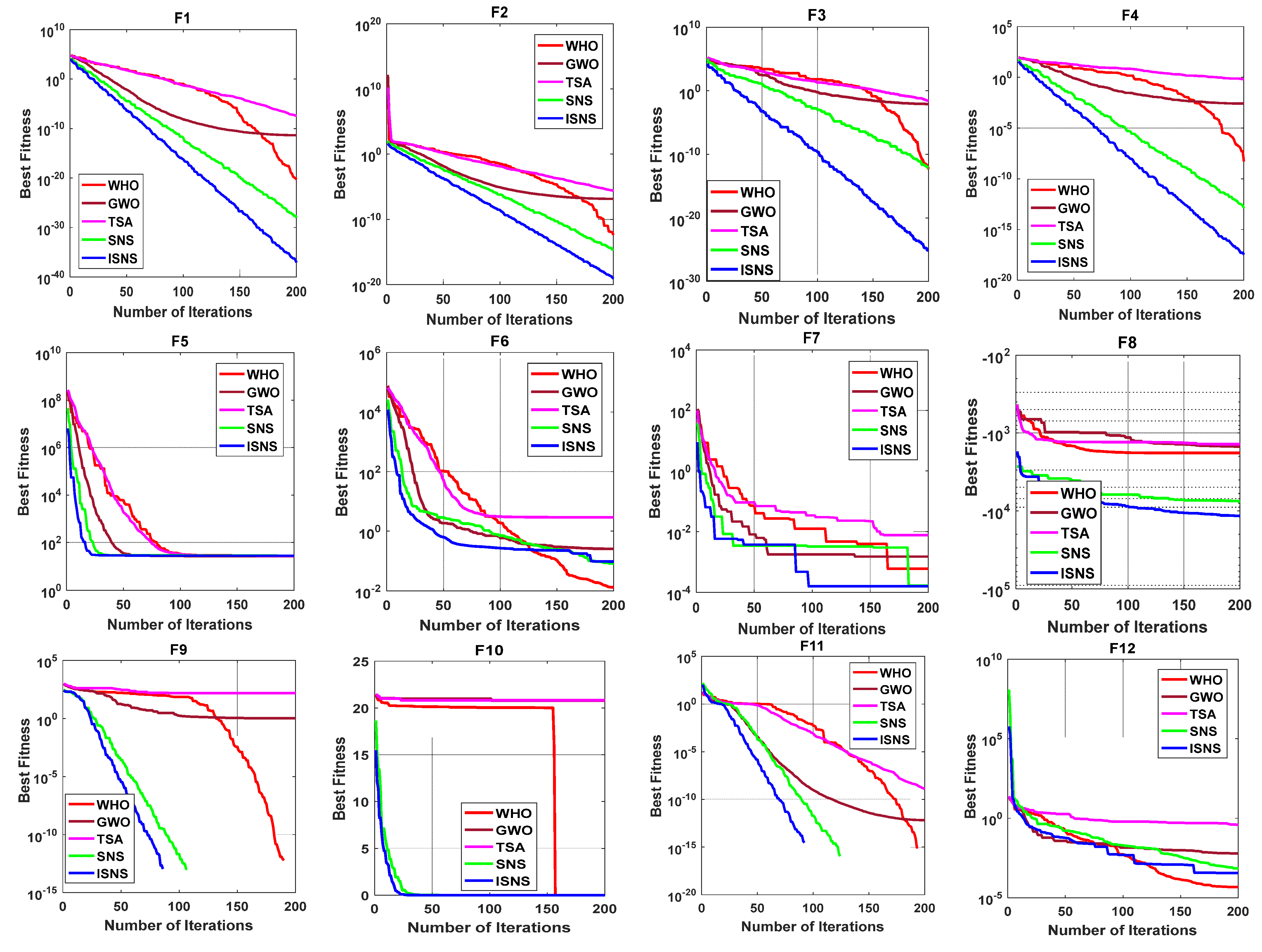
Comparing the performance of the proposed ISNS algorithm with other algorithms (i.e., PSO, TSA, GWO, and WHO) in terms of fitness values using 23 benchmark test functions.
-
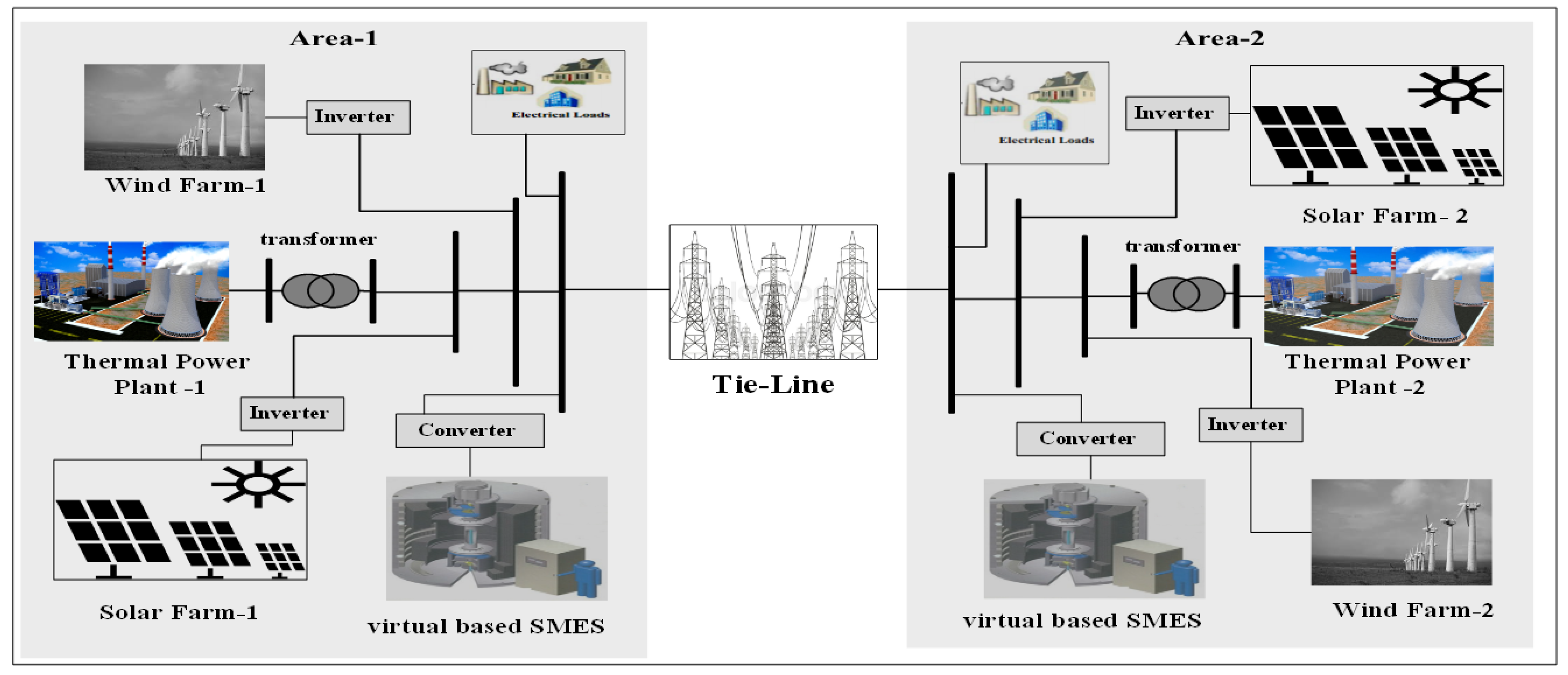
Considering a hybrid power system that combines conventional power plants (e.g., reheat power plants), renewable power plants (e.g., wind farms and solar farms), energy storage devices (e.g., SMES technology), and high load disturbance to conduct a realistic study of the frequency stability issue for current power grids.
-
Based on the authors’ knowledge, it is the first attempt to select the optimal control gains of VIC based on SMES technology to increase the stability of the considered system.
-
Comparing the system’s performance based on the proposed strategy with the system performances based on optimal VIC-based traditional ESS, and with the system performance without VIC.
-
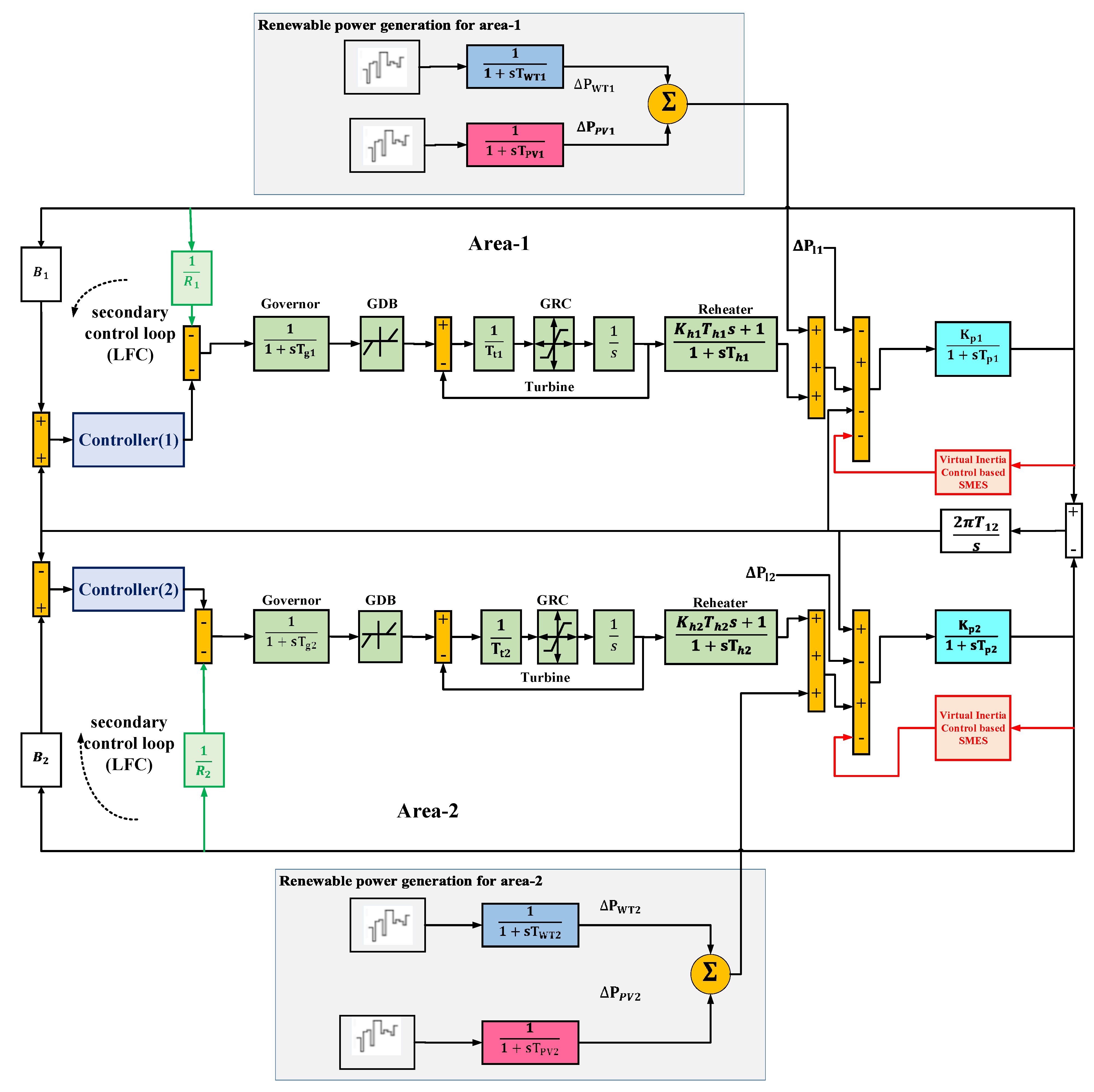
Considering the system non-linearities (e.g., governor dead band (GDB) and generation rate constraint (GRC)) in the presence of uncertainties of RESs/loads. Additionally, considering GRC with the virtual loop design.
The following are excerpts from the paper: Section 2 outlines the modelling and construction of the proposed power system, taking RESs and the VIC dependent on SMES technology into account. Section 3 discusses the formulation of the problem, control approaches, and the improved SNS algorithm. Section 4 presents the effectiveness of the proposed ISNS algorithm. Then, Section 5 shows the simulation results. Furthermore, the main conclusion is stated in Section 6.

2. System Dynamics

2.1. The Modelling of the System under Consideration

A hybrid two-area interconnected power grid has been presented in this study considering renewables penetration, systems uncertainties, system non-linearities, and VIC depending on SMES technology. Each power grid comprises generating thermal unit, wind farm, and solar power stations. Furthermore, Figure 1 depicts a schematic representation model for the electrical grid under consideration. Figure 2 describes a block diagram of the proposed two-area connected hybrid power grid considering VIC dependent on SMES technology. Each area’s rated power capacity is 2000 MVA, the rated load demand is 1000 MW, and the system power base is 2000 MVA. Furthermore, the non-linearity of the studied system is achieved by adding GRC with a value of 5% p.u to the turbine model for referring to the change in the power turbine rate as well as its limitations. The values of the parameters of the examined two-area power grid are presented in Appendix A [42]. The model of RESs has been implemented using low-order dynamic models that are adequate for investigating the LFC problem. Therefore, load demand, wind power, and PV power are classified as power grid disruptive sources [42,46].
The relationship of incremental mismatch power ( Δ P m i Δ P L i + Δ P W T i + Δ P P V i ) and the Δ f i ˙ can be expressed as:
Δ f i = K p i T p i s + 1 [ Δ P m i Δ P L i Δ P t i e , i + Δ   P W T i + Δ   P P V i + Δ   P i n e r t i a i ]
Moreover, the dynamic of the governor can be represented as:
Δ P g i ˙ = ( 1 T g i ) Δ P c i ( 1 R i T g i ) Δ f i ( 1 T g i ) Δ P g i  
The dynamic of the turbine can be represented as:
Δ P m i ˙ = ( 1 T t i ) Δ P g i ( 1 T t i ) Δ P m i  
In addition, the dynamic model of wind turbine can be represented as:
Δ P ˙ W T i = ( 1 T W T i ) · P w i n d , i ( 1 T W T i ) · Δ P W T , i
Furthermore, the dynamic model of solar plant can be represented as:
Δ P ˙ P V i = ( 1 T P V i ) · P s o l a r , i ( 1 T P V i ) · Δ P P V , i
Then, the total tie-line power change can be represented as follows:
Δ P ˙ t i e , i = j = 1 j i n Δ P t i e , i j = 2 π · [ j = 1 j i n T i j Δ f i j = 1 j i n T i j Δ f j ]
In the supplementary feedback loop, ACE should be applied to regulate the frequency of interconnected power system. ACE can be represented as follows:
A C E i = B i Δ f i + Δ P t i e , i
where Δ P m i symbolizes the mechanical power deviation of area i,   Δ P L i symbolizes he load change of area i, Δ P t i e , i signifies the deviations of the tie-line power among area-i,  Δ   P W T i signifies the wind turbine’s output power of area i, Δ   P P V i signifies the PV system’s output power of area i, T g i denotes the governor’s time constant of area i, T t i denotes the turbine’s time constant of area i, K h i represents the reheater gain of area i, T h i represents the time constant of the reheater of area i, R i denotes the governor’s speed regulation of area i,   Δ P c i denotes the regulating of the system frequency of reheat power plant of the area i, T W T i denotes the wind turbine time constant of area i, Δ P w i n d , i denotes the wind power variation of area i,   T   P V i represents the PV time constant of area i, Δ P s o l a r , i denotes the solar power variation of area i. n represents the number of the controlled area,   K P i represents the power system gain of area i, T P i represents the power system’s time constant of area i, T i j represents the synchronization time between two controlled areas, B i represents the area bias factor, and A C E i is the area control error of area i.

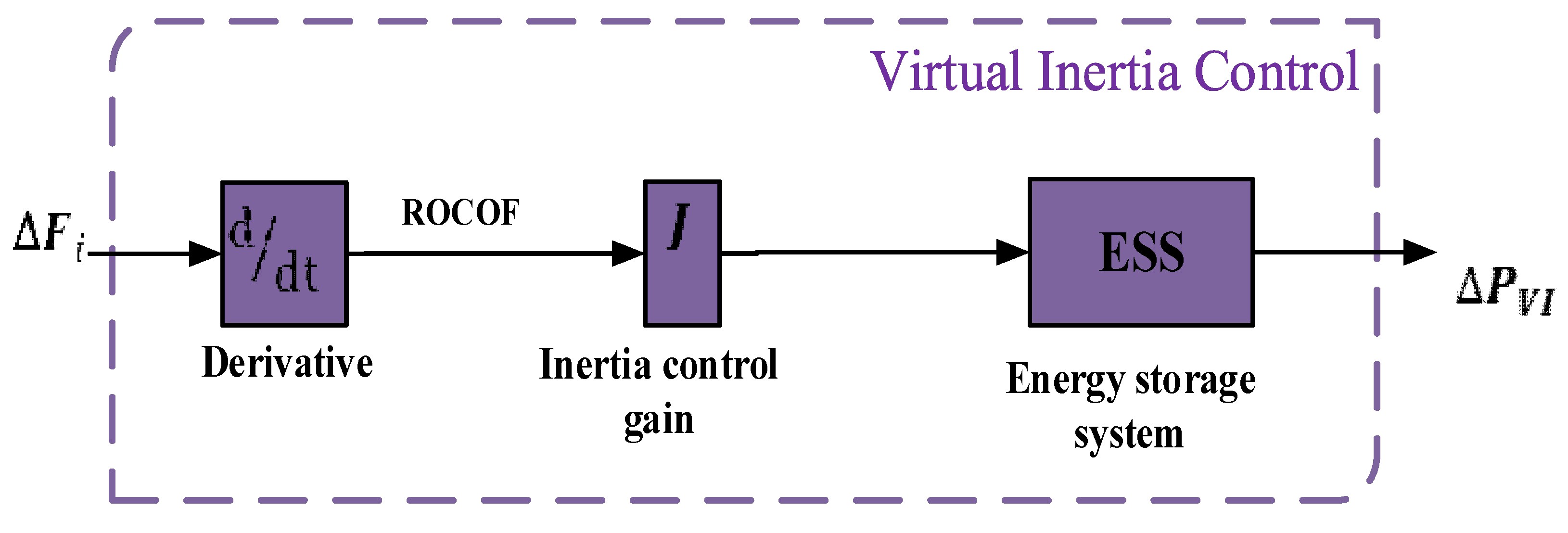
2.2. Modeling of Virtual Inertia Control Loop

A tremendous amount of effort has been made to keep our environment clean by reducing the items that distribute carbon. One of these items is conventional power plants. As a result, countries are beginning to replace these conventional power plants with modern power plants that emit no carbon (i.e., RESs). RESs use power converters to connect to the grid; these converters reduce system inertia and affect system stability. Furthermore, virtual control has been implemented to deal with this reduction of system inertia and enhance the stability of the system. Additionally, the dynamic model of the virtual inertia control system (VIC) loop has been displayed in Figure 3. According to this figure, the derivative control takes into account the main concept of VIC, which can evaluate the rate of change of frequency to compensate for the additional power at the set point during the penetration of RESs in the system. On the other hand, the derivative control technique is extremely sensitive to the noise of frequency observations [25]. To address this issue, a low-pass filter is used to control the system. Furthermore, the low-pass filter can provide dynamic ESS behaviors. As a result, the proposed VIC generates the inertia feature, which contributes to the overall inertia of the power grid network and enhances frequency reliability and performance. In this strategy, the ESS is assumed to generate virtual inertia power in the hybrid power grid. Therefore, the VIC can deliver the desired power to the hybrid power grid as follows [24]:
Δ   P i n e r t i a , i = K V I , i 1 + s T V I , i [ d ( Δ f i ) d t ]

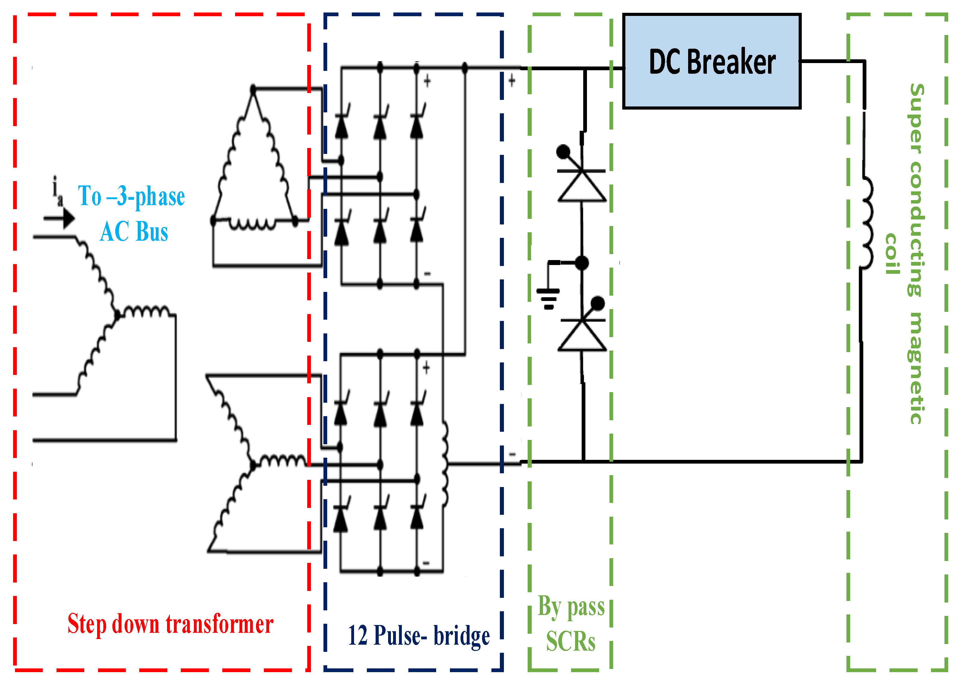
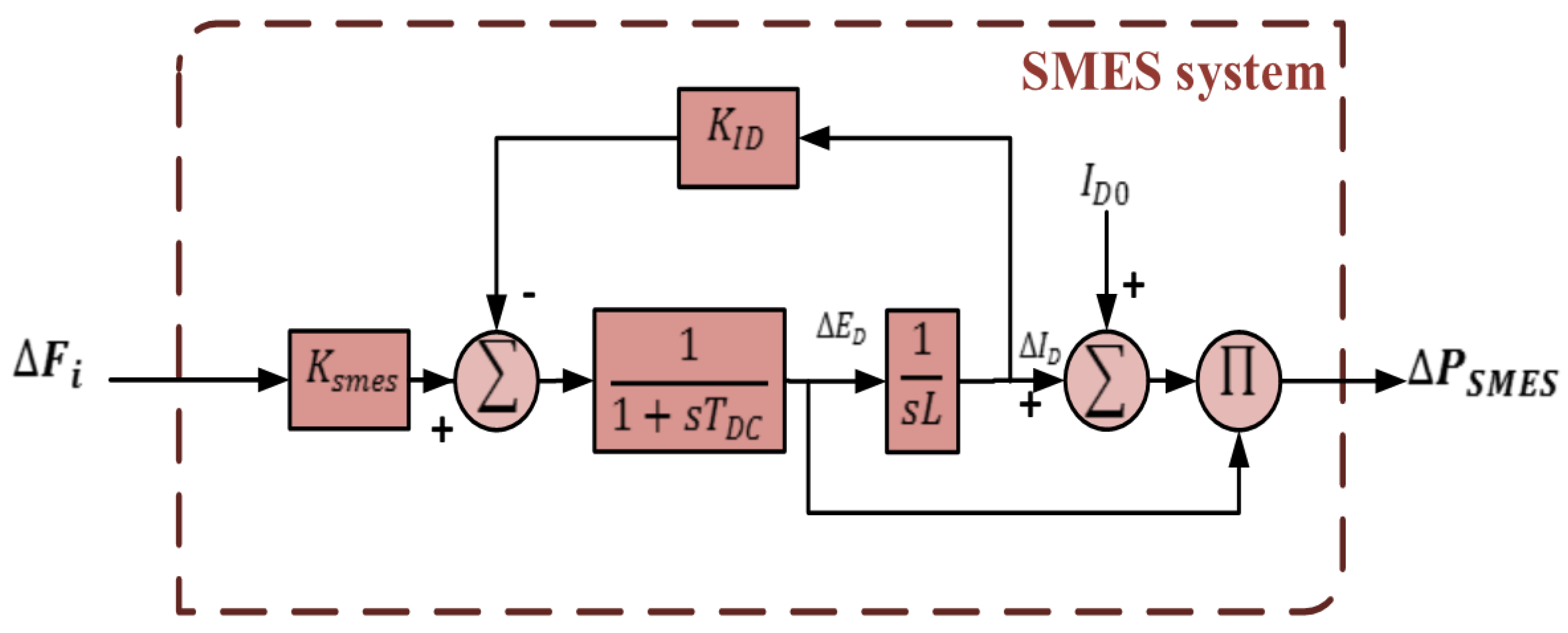
2.3. Modelling of the SMES Technology

SMES may give an infinite number of charging/discharging cycles with a quicker reaction time as well as has the longest lifetime in comparison to other ESSs [47]. The SMES’s basic form has been displayed in Figure 4. It is clear from Figure 4 that the SMES consists of a Wye-Delta transformer, an AC/DC thyristor-controlled bridge converter, and a superconducting magnetic inductor/coil. The power conditioning system (PCS), which includes the rectifier/inverter, is in charge of managing power transmission between both the AC bus/system and the magnetic coil. The 12-pulse converter has been applied to diminish any harmonic-generated voltage from the coil. During the power system’s regular steady-state operation, the SMES coil is charged from the grid to its current value in a very short period of time. The SMES coil begins carrying DC current with practically 0% loss in its charged condition because the coil temperature is kept at an exceptionally low range. Furthermore, the resulting DC voltage is expressed as follows:
E d = 2 V d o cos 2 I d R c
Here, V d o represents the maximum circuit bridge voltage, I d represents the current flowing through the inductor, and R c is the damping resistor. The firing angle ( ) affects the charging and discharging of the SMES, according to the previous relationship. If the firing angle is greater than 900, the SMES coil starts to charge due to the positive value of the average voltage. On the other hand, if the firing angle is less than 900, the SMES coil starts to discharge due to the negative value of the average voltage. Referring to the exceptional benefits of the SMES, it is useful to apply the SMES in power systems for maintaining the frequency, particularly during transitory instances of either the load or the RESs. Furthermore, the dynamic model of SMES, which is required for the frequency stability, is shown in Figure 5.
Here, the frequency deviation ( Δ F ) is considered as the input signal to the SMES model to generate the required power ( Δ P S M E S ), which is supplied to the power system. The generated power from the SMES model can be expressed according to the following relations [35]:
Δ P S M E S = Δ E D ( Δ I D + I D O )
where Δ E D represents the inductor voltage deviations and can be expressed according to the following equation:
Δ E D = K S M E S 1 + s T D C · ( Δ F ( K I D . Δ I D ) )
At this point, K S M E S represents the control gain for the SMES loop, T D C represents the convertor time constant of the SMES, K I D represents the feedback gain, and Δ I D represents the inductor current deviation. In addition, the inductor current deviations can be expressed as follows:
Δ I D = 1 s   L · Δ E D
Here, L represents the induction coil [35]. In this study, the utilized parameters of the SMES system have been listed in [48].

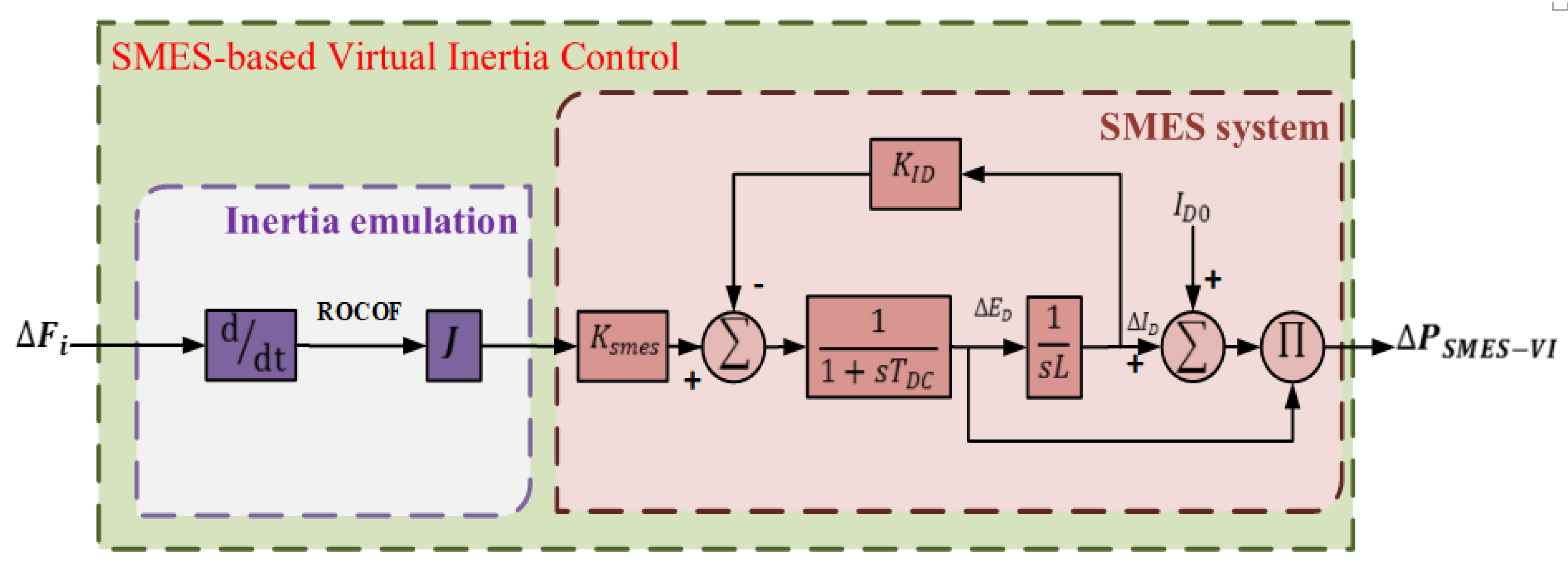
2.4. Modeling of SMES Based VIC

The configuration of the proposed strategy VIC based on SMES technology has been displayed in Figure 6. Here, the VIC has depended on the SMES technology instead of ESS devices. In this study, the gain of the VIC and the gain of SMES technology have been selected by ISNS optimization algorithm. Furthermore, the resulted inertia power from this strategy can be expressed as follows:
Δ P S M E S V I = J   K S M E S 1 + s T D C ( d ( Δ F ) d t K I D · Δ I D ) · ( I D O + Δ I D )

3. The Statement of the Problem and the Recommended Solution

3.1. The Proposed Algorithm

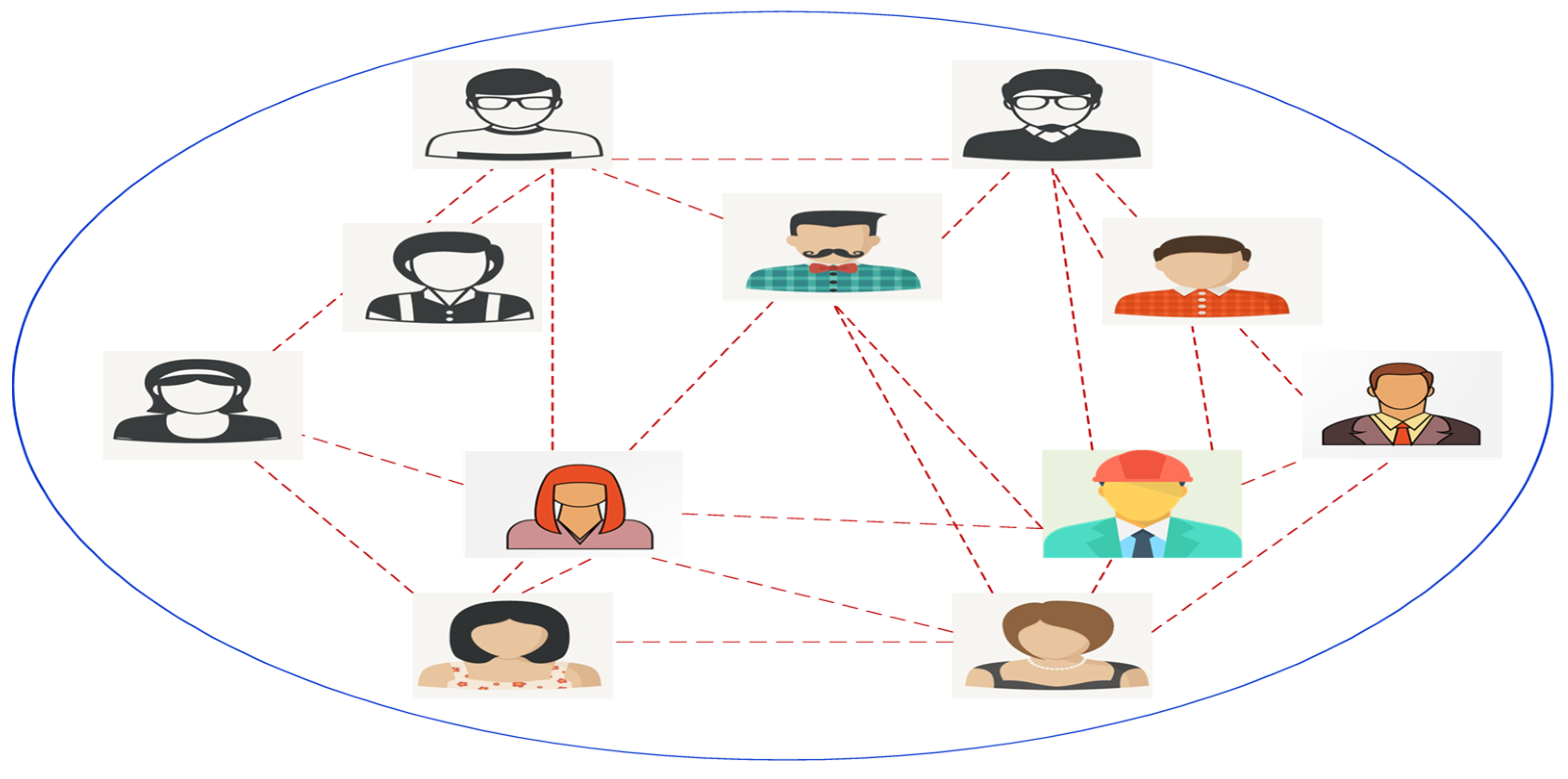
3.1.1. Social Network Search (SNS)

The SNS algorithm mimics the users’ efforts in social networks to get further popularity by modeling the users’ moods in expressing their views. Those moods are called imitation, conversation, disputation, and innovation, and are real-world behaviors of users in social networks. The general model for a social network is shown in Figure 7.
The mathematical modeling of those moods is represented as follows:
  • Imitation
X i , n e w = X j + rand ( 1 , 1 ) × M M = rand ( 0 , 1 ) × h h = X j X i
where X j is the vector of the jth user’s view, which is chosen randomly, and i ≠ j and X i represent the vector of the ith user’s view.
2.
Conversation
X i , n e w = X k + M M = rand ( 0 , 1 ) × B B = s i g n ( f i f j ) × ( X j X i )
where X k is the vector of the issue, which is chosen randomly as something to speak about.
3.
Disputation
X i , n e w = X i + rand ( 0 , 1 ) × ( G AF × X i ) G = t N r X t N r A F = 1 + r o u n d ( r a n d )  
where X i is the vector of the view of the ith user and G demonstrates the mean of the commenters’ views in the group. AF represents the admission factor. N r denotes the group size.
4.
Innovation
X i , n e w d = t × X j d + ( 1 t ) × n n e w d n n e w d = l b + r a n d 1 × ( u b l b ) t = r a n d 2
where d denotes the dth variable, which is chosen randomly in the interval of the variables of the problem.   n n e w d is the new idea while x j d represents the current idea.
This process is modeled as follows:
X i , n e w = [ x 1 ,   x 2 ,   x 3 ,   . . x i , n e w d x D ]
To find the value of the new view, the objective functions of X i , n e w and X i must be calculated and then compared, and the new value of X i for the minimization problem is calculated from the following equation:
X i = { X i , f ( X i ) < f ( X i , n e w ) X i , n e w , f ( X i , n e w ) f ( X i )

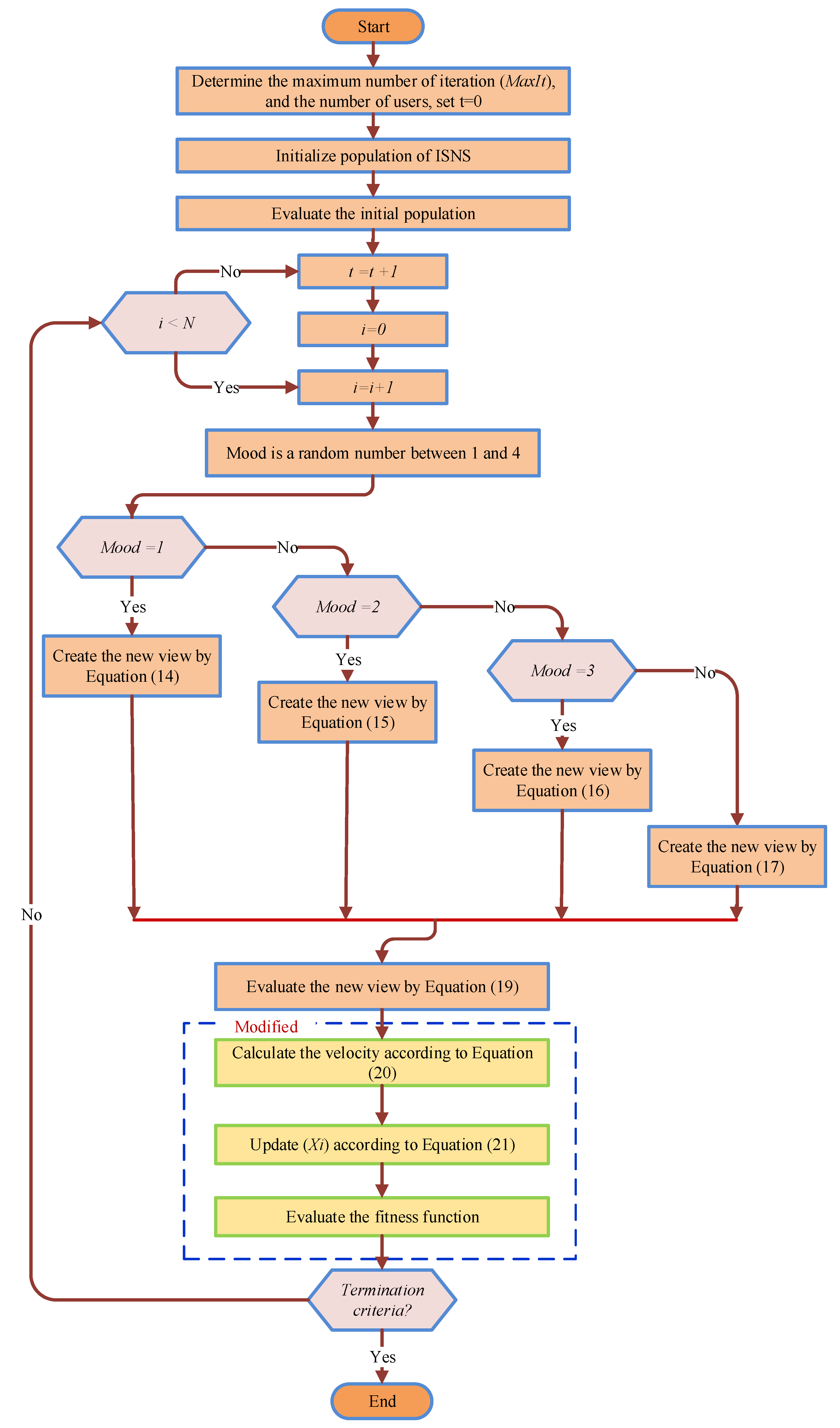
3.1.2. Improved Social Network Search (ISNS)

In order to develop the strength of the proposed ISNS technique for several high-dimensional optimization problems, the way is utilization from the primary of one of the best meta-heuristic algorithms, which is named particle swarm optimizer (PSO). The PSO technique is presented by [49]. The velocity equation of the PSO algorithm is employed in the ISNS technique. This amendment managed to modify the ability of the global search and local search capabilities of the enhanced technique. This essential equation is as follows:
V i k ( t + 1 ) = w · V i k ( t ) + C 1 · r 1 × ( p b e s t X i k ( t ) ) + C 2 · r 2 × ( g b e s t X i k ( t ) )
X i k ( t + 1 ) = X i k ( t ) + V i k ( t + 1 )
where C 1 = C 2 = 0.5 and these values provided the optimal solution in [49], w = 0.7 , r 1 and r 2 denote a random number in the range [0, 1], p b e s t is the optimum solution of a single population, and g best is the optimal solution so far. The flow chart of the ISNS technique is presented in Figure 8.

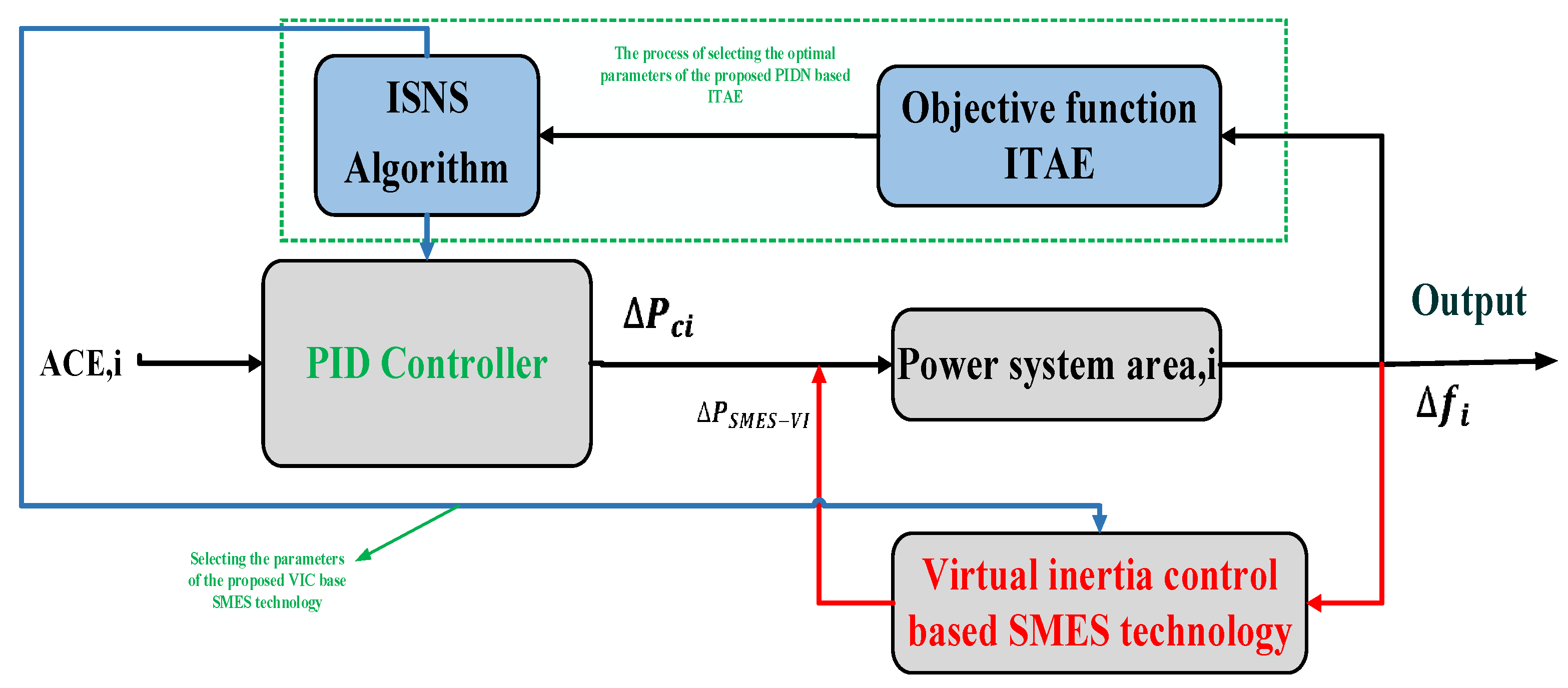
3.2. The Proposed Control Strategy

The proposed control strategy in this study is based on the LFC loop and the VIC to maintain the stability of the system. The reason for applying VIC to the control strategy is the high renewable power penetration. Here, the LFC loop is implemented based on the PID controller due to its simplicity in construction. Moreover, the VIC is implemented based on SMES technology instead of ESS. Furthermore, the ISNS algorithm has been applied to select the optimal parameters of the PID controller in SCL and the control gains (i.e., inertia control gain and SMES control gain) for the VIC-based SMES technology. The gains of the PID controller have been selected according to the following relationship:
G c ( s ) = K P + K i 1 s + K d N 1 + N 1 s
Here, kd denotes the derivative gain, ki denotes the integral gain, kp denotes the proportional gain, and N denotes derivative filter coefficient. Moreover, the inertia control gain and SMES control gains of the VIC based SMES technology have been selected according to Equation (12).
Furthermore, an efficient objective function has been applied to minimize the deviations of the considered system and select the optimal parameters that keep the system stable. In this regard, four separate forms of objective functions are being used in the design procedure for the controller: Integral Absolute Error (IAE), Integral Time Weighted Absolute Error (ITAE), Integral Square Error (ISE), and Integral Time Weighted Square Error (ITSE). According to the previous studies, to produce better performances, the ISE and ITAE objective functions are frequently used in LFC investigations. When compared to the ISE objective function, the ITAE objective function takes less time. In this regard, the ITAE is the objective function that is used to solve the optimization problem in this study, and it is written as follows:
I T A E = 0 t s { | Δ f 1 | + | Δ f 2 | + | Δ P t i e | } . t . d t
This is subject to the following PID controller variable boundaries:
K P , i , d   m i n m K P , i , d m K P , i , d   m a x m   m N P I D
N m i n m N m N m a x m       m N P I D          
Furthermore, the boundary of the inertia gain and the control gain of SMES technology are described in the following relation:
J m i n J J m a x
K S M E S , m i n K S M E S K S M E S , m a x
K I D , S M E S , m i n K I D , S M E S K I D , S M E S , m a x
where ts signifies the optimization process’s simulation time, ( Δ f 1 ) , ( Δ f 2 ) signifies the frequency deviances of area-1 and area-2 correspondingly, ( Δ P t i e 1.2 )   signifies the tie-line power change between area-1 and area-2,   K P , i , d   m i n m and K P , i , d   m a x m signify the specified range limits of the PID controller gains of mth PID controller, N m i n m and N m a x m signify the specified range limit of the filter coefficient of mth PID controller, and N P I D signifies the number of the PIDs. Additionally, the PID controller settings are in the collection from [0, 10] and the filter coefficient settings are in the choice of [0, 100], which are used in the industry for elucidating the LFC issue [42]. Moreover, J signifies the inertia gain,   K S M E S signifies the SMES proportional gain, and K I D , S M E S signifies the SMES negative feedback gain. Furthermore, the inertia settings are in the choice of [0.1, 3], and SMES proportional lies in the range of [0.1, 3], and negative feedback gain settings are in the choice of [0.01, 0.1] [36]. Moreover, Figure 9 displays the process of selecting the optimal control gains of the proposed PID controller and proposed VIC-based SMES technology.

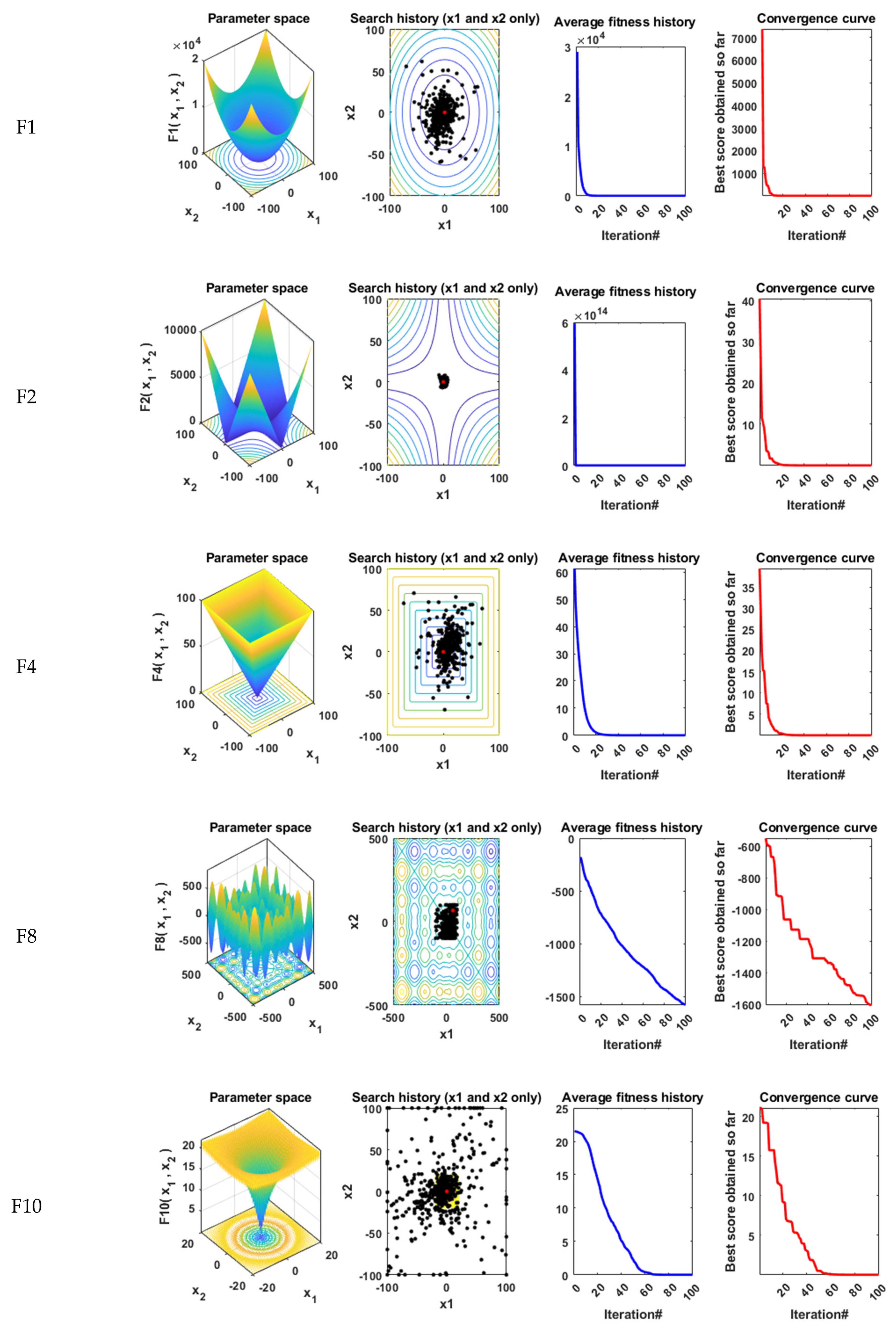
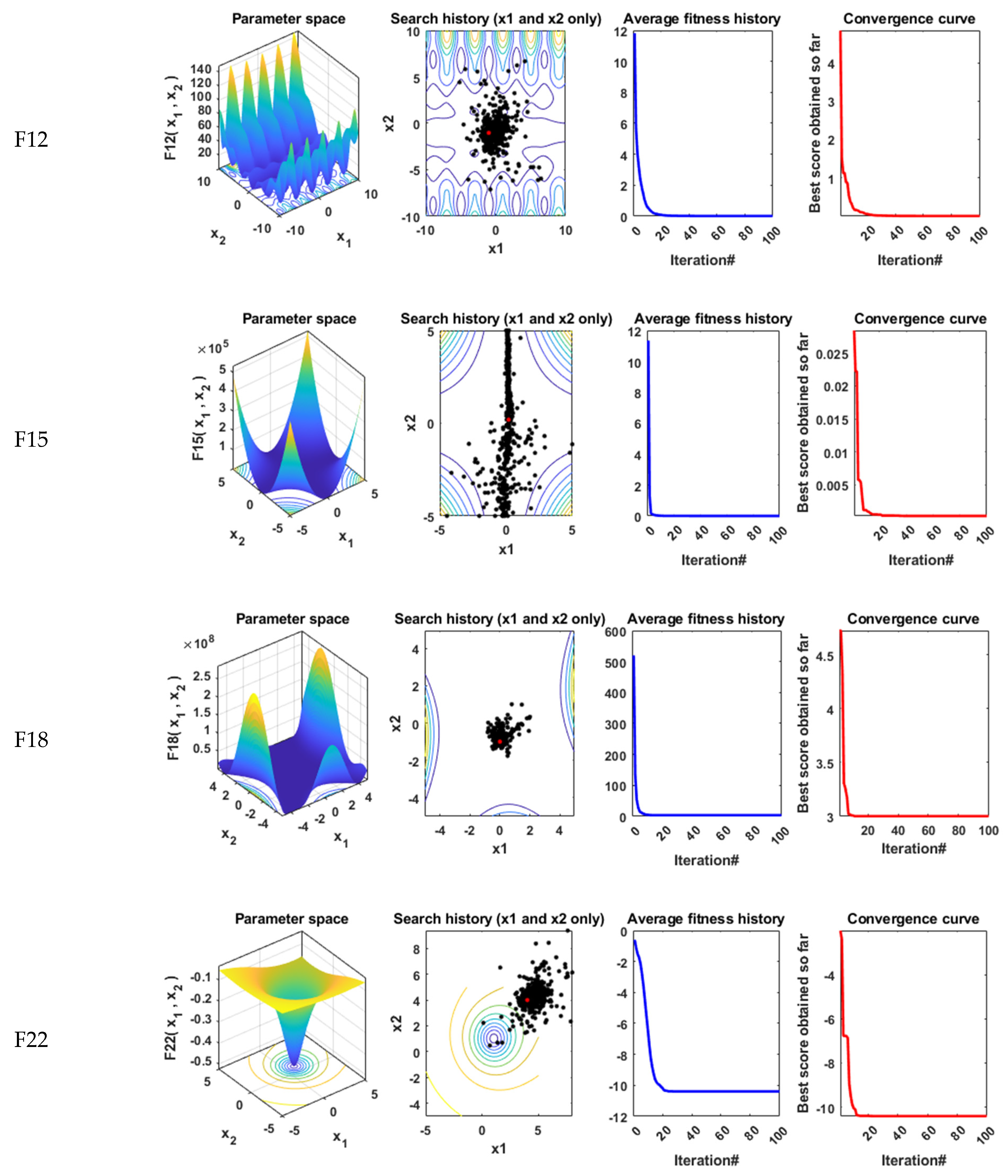
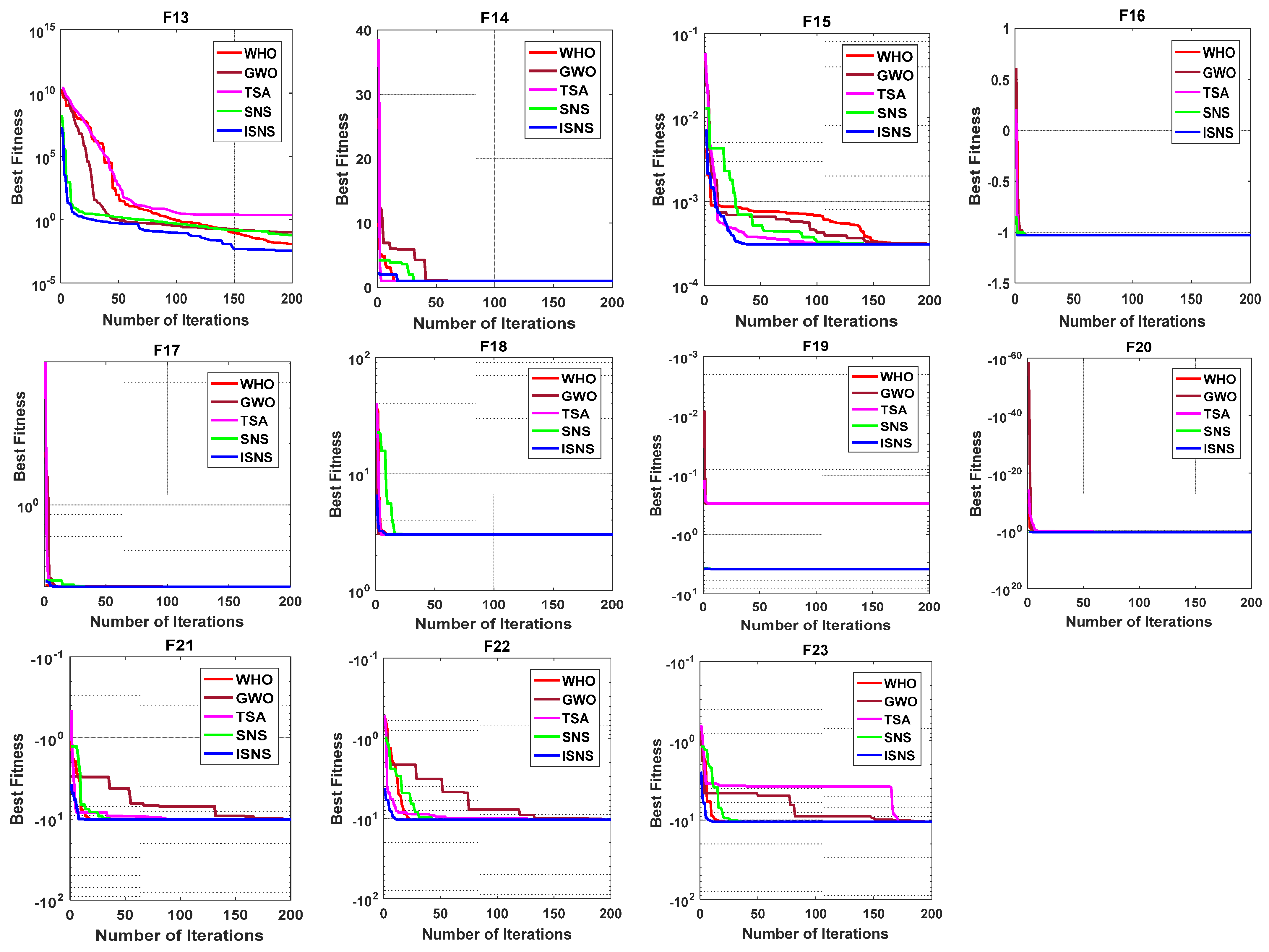
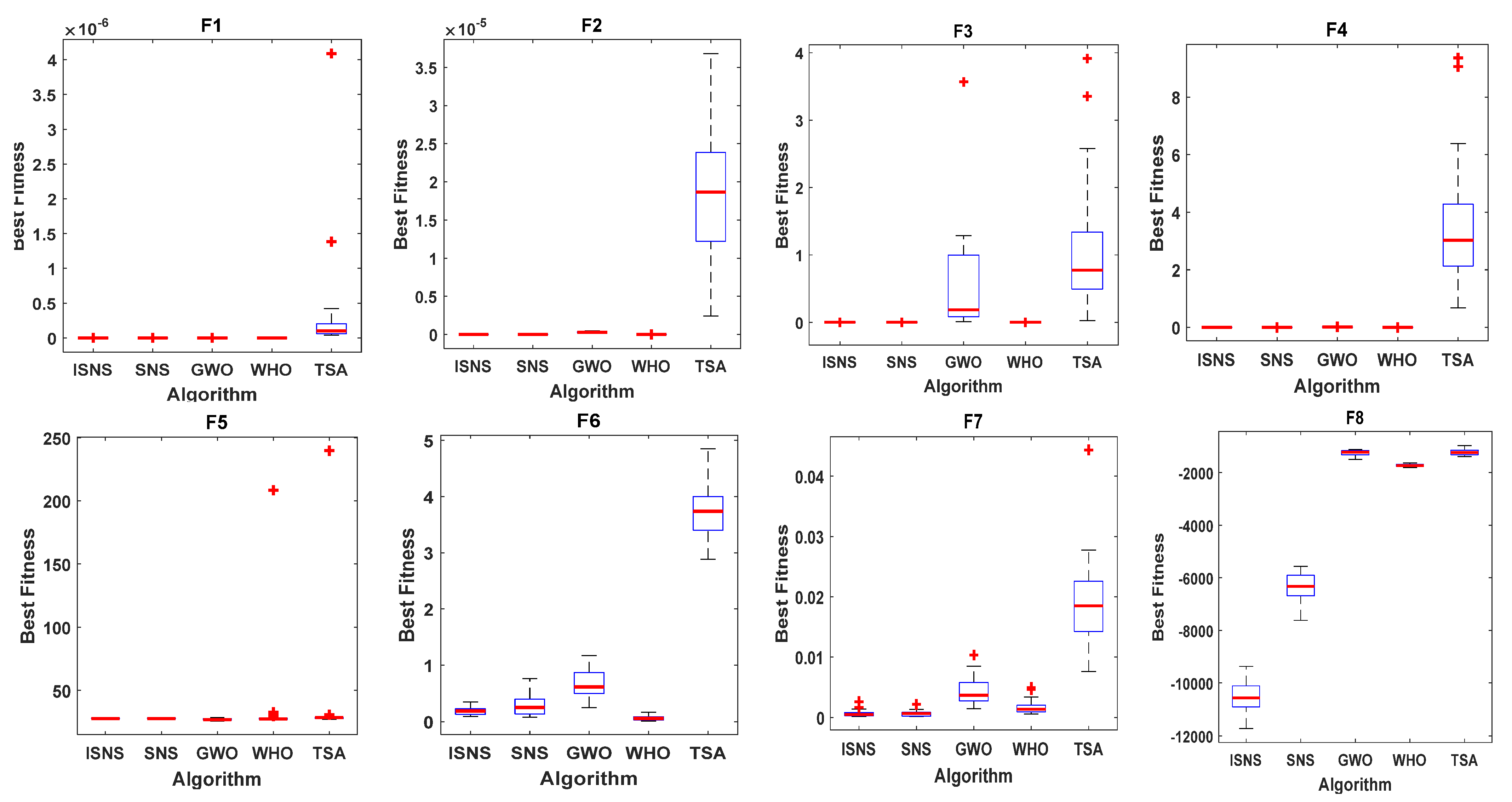
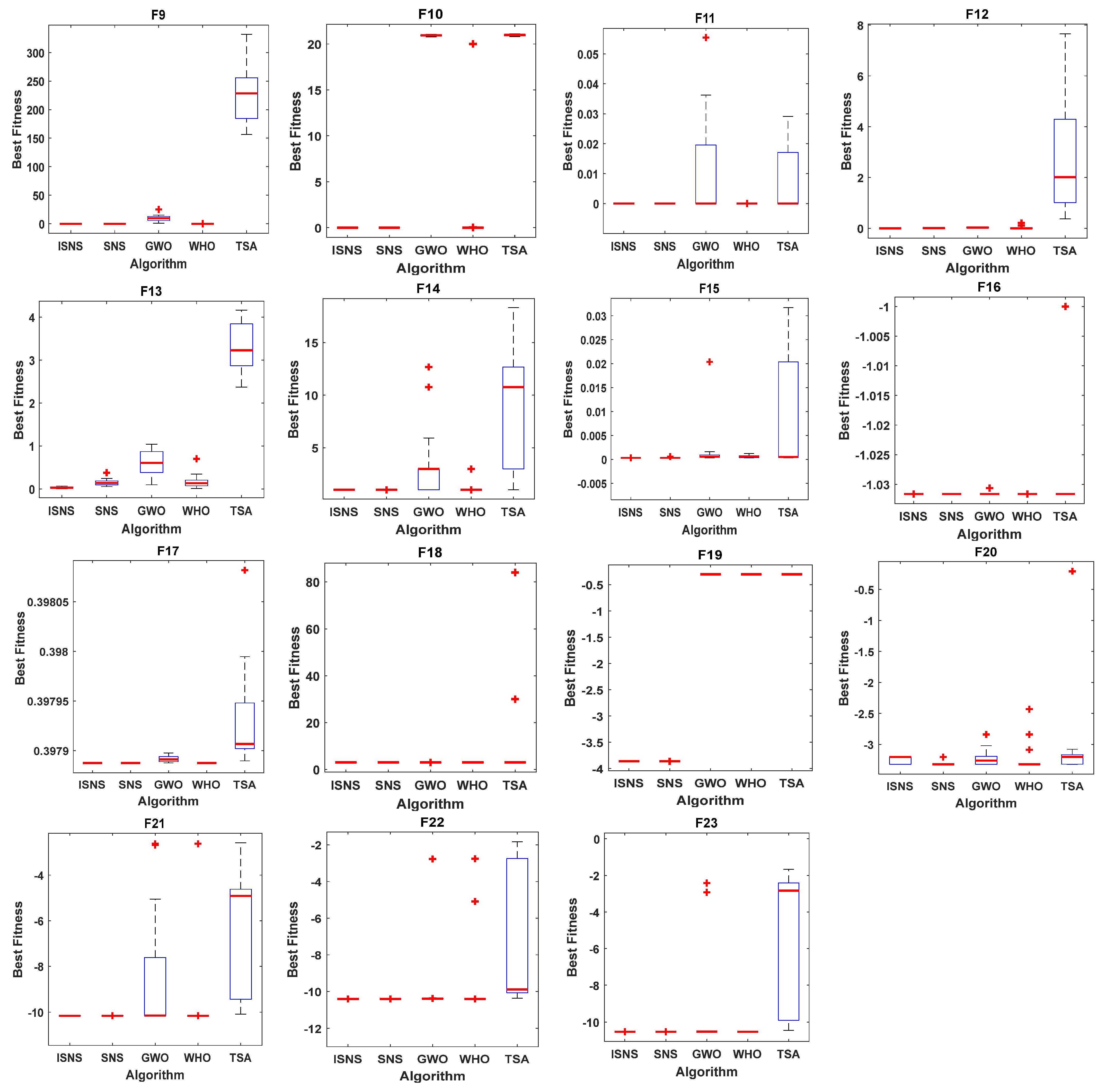
4. Performance Analysis of the Improved SNS Algorithm

Benchmark Functions

In this subsection, the qualitative metrics by the ISNS algorithm for 12 benchmark functions such as 2D views of the functions, search history, average fitness history, and convergence curve are displayed in Figure 10. The efficiency and the accuracy of the ISNS technique are assessed for 23 benchmark functions, including the values of the best, mean, median, worst, and standard deviation (STD) for the solutions attained by the original SNS technique, and three well-known algorithms, including the tunicate swarm algorithm (TSA) [50], the gray wolf optimizer (GWO) [51], and wild horse optimizer (WHO) [52], are displayed in Table 1. The benchmark functions F1–F13 are tested in 30 dimensions while the population size and maximum iteration number of each algorithm are 50 and 200, respectively. It can be noticed that the ISNS technique offers superior results on most of these functions in the best, median, worst, mean, and std values. The convergence curves of these techniques for these functions are presented in Figure 11. For more analysis to confirm the performance of the recommended technique, a boxplot of outcomes for each technique and objective function is demonstrated in Figure 12.

5. Simulation Results

The system under consideration in this study was constructed using the MATLAB software with the Simulink option. In addition, the ISNS algorithm was developed using the m.file option in the MATLAB software to execute the optimization process to determine the optimal PID controller parameters for each region as well as the control gains of the VIC based on SMES technology in the system under consideration. The simulation results have been performed on a laptop with an Intel Core i5-2.6 GHz, 4 GB RAM. Moreover, the performance of the studied system is estimated under various operating situations, according to the following scenarios:
  • Scenario 1: Estimation of system performance considering various optimization techniques.
  • Scenario 2: Estimation of system performance considering low and high renewable power penetration.
  • Scenario 3: Estimation of system performance considering high renewable power penetration and optimal VIC-based SMES technology.
  • Scenario 4: Estimation of system performance considering high renewable power penetration, low of system inertia, and optimal VIC based SMES technology.

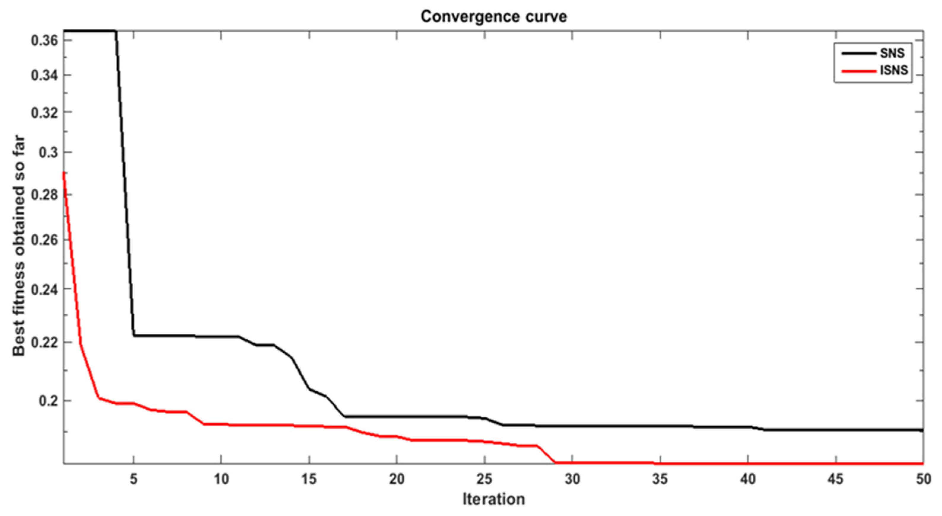
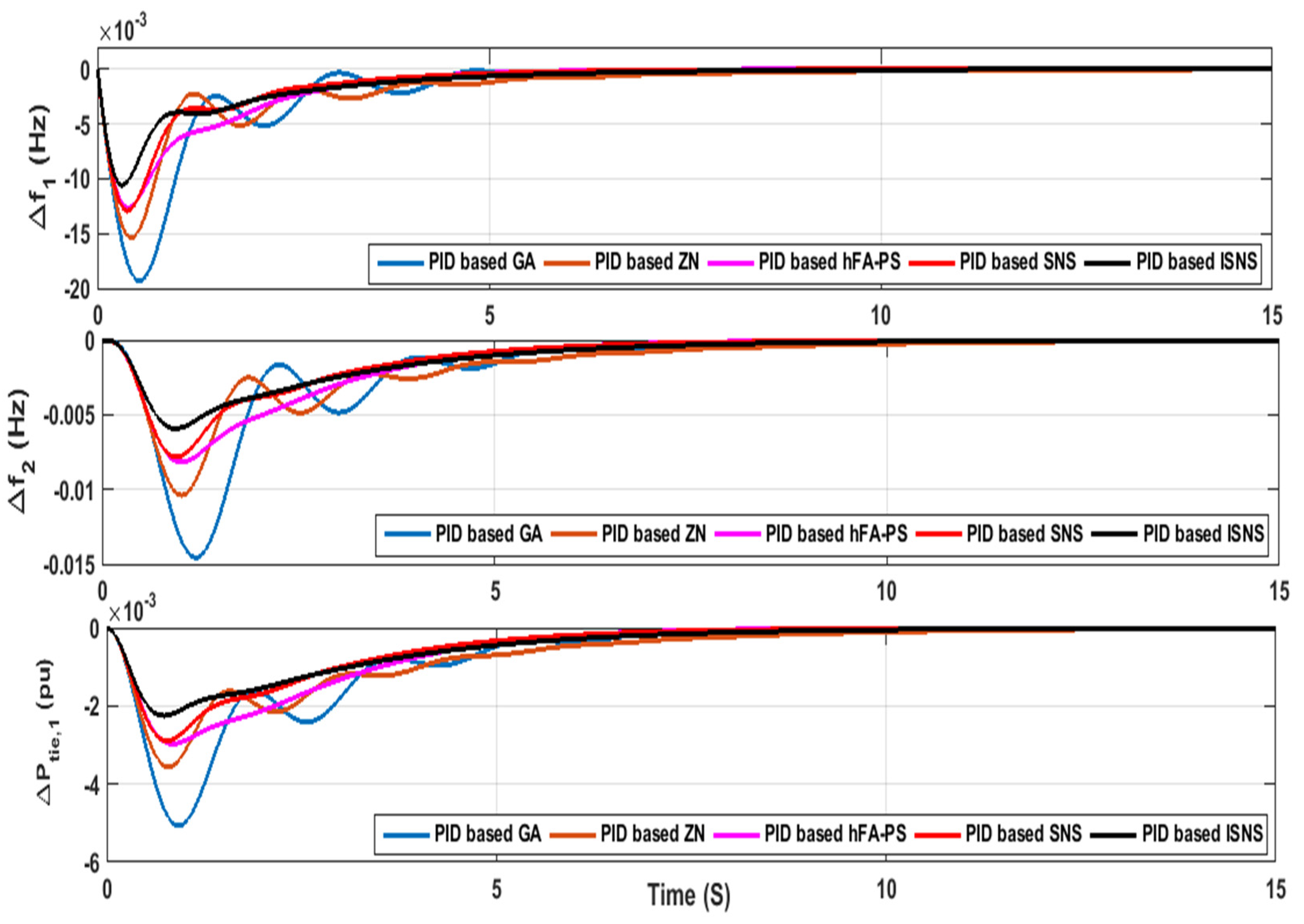
5.1. Scenario 1: Estimation of System Performance Considering Various Optimization Techniques

The main goal of this scenario is to validate the superiority of the proposed ISNS algorithm over other optimization algorithms such as SNS algorithm, firefly algorithm (FA) [53], conventional Ziegler Nichols (ZN) [53], and a hybrid firefly algorithm and pattern search technique (hFA-PS) [54]. The comparison has been made considering 5% step load perturbation (SLP) in area-1 in the beginning of simulation time where the system constraint (i.e., generation rate constraint) has been considered in the two areas. Additionally, the ITAE has been considered as an objective function to evaluate the value of system output deviations. The optimal parameters of the proposed controller are listed in Table 2. Additionally, Table 3 lists the performance indices of the considered system based PID controller considering various optimization algorithms. Moreover, the convergence curve of the proposed PID controller-based ISNS algorithm and PID controller-based SNS algorithm has been displayed in Figure 13. Furthermore, Figure 14 displays the performance of the considered system in terms of frequency deviations for the two area and tie line power deviations. It is clear from Table 3 that the value of the objective function based on ISNS algorithm is the best in comparison to other optimization algorithms. Additionally, the proposed PID-ISNS enhanced the system performance than PID-GA, PID-ZN, and PID-hFA-PS by 97%, 51%, 23%, respectively.

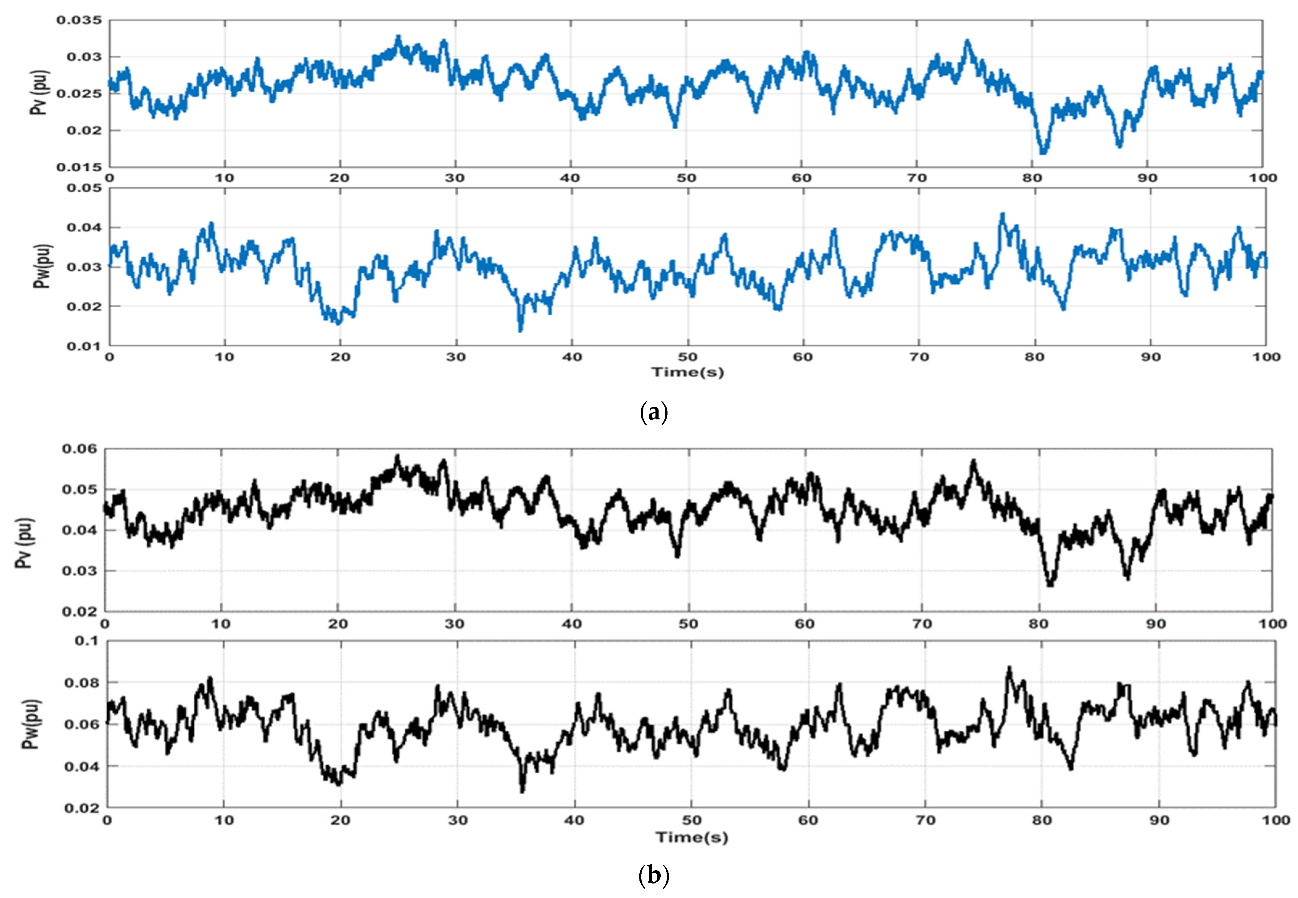
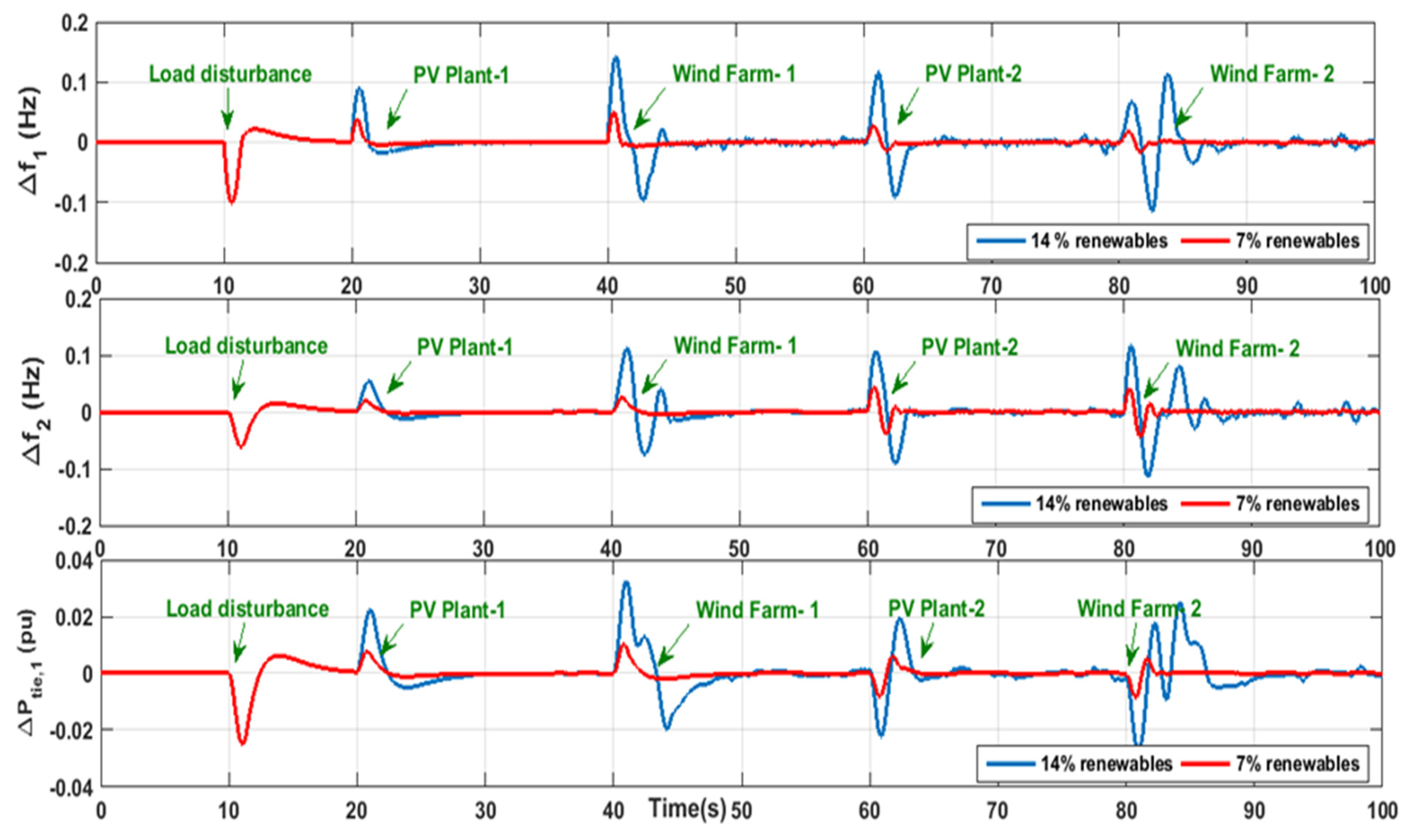
5.2. Scenario 2: Estimation of System Performance Considering Low and High Renewables Power Penetration

The performance of the proposed PID controller based on ISNS algorithm has been checked by considering renewable power sources that linked to the considered two area power system in the presence of system nonlinearities and high load disturbance. Furthermore, Figure 15a displays the resulted output power from the PV power station and wind farm in case of low renewables penetration, while Figure 15b displays the resultant output power from the PV power station and wind farm in case of high renewables penetration. Moreover, Table 4 lists the optimal parameters of the proposed PID controller-based ISNS algorithm. Furthermore, the operating conditions of this scenario have been listed in Table 5. The system response considering renewable power penetration (i.e., 7% penetration, and 14% penetration) based on the proposed PID controller-based ISNS algorithm is shown in Figure 16. The proposed PID controller-based ISNS algorithm moderates the frequency deviance as well as the steady state errors and needs small settling time.

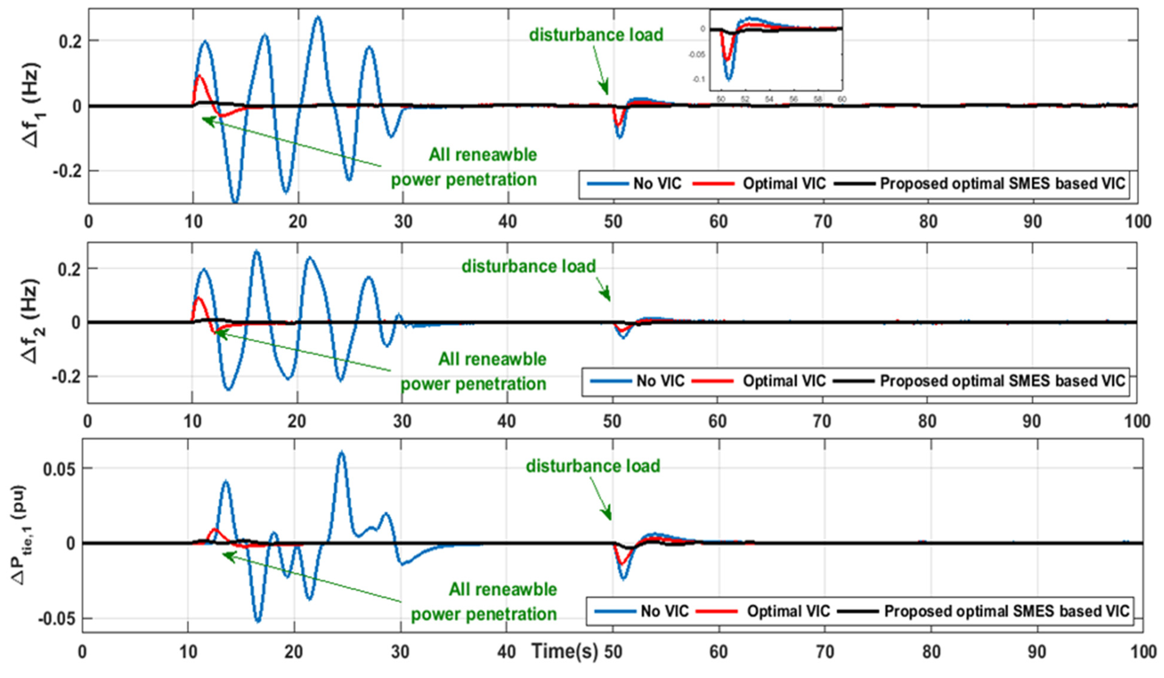
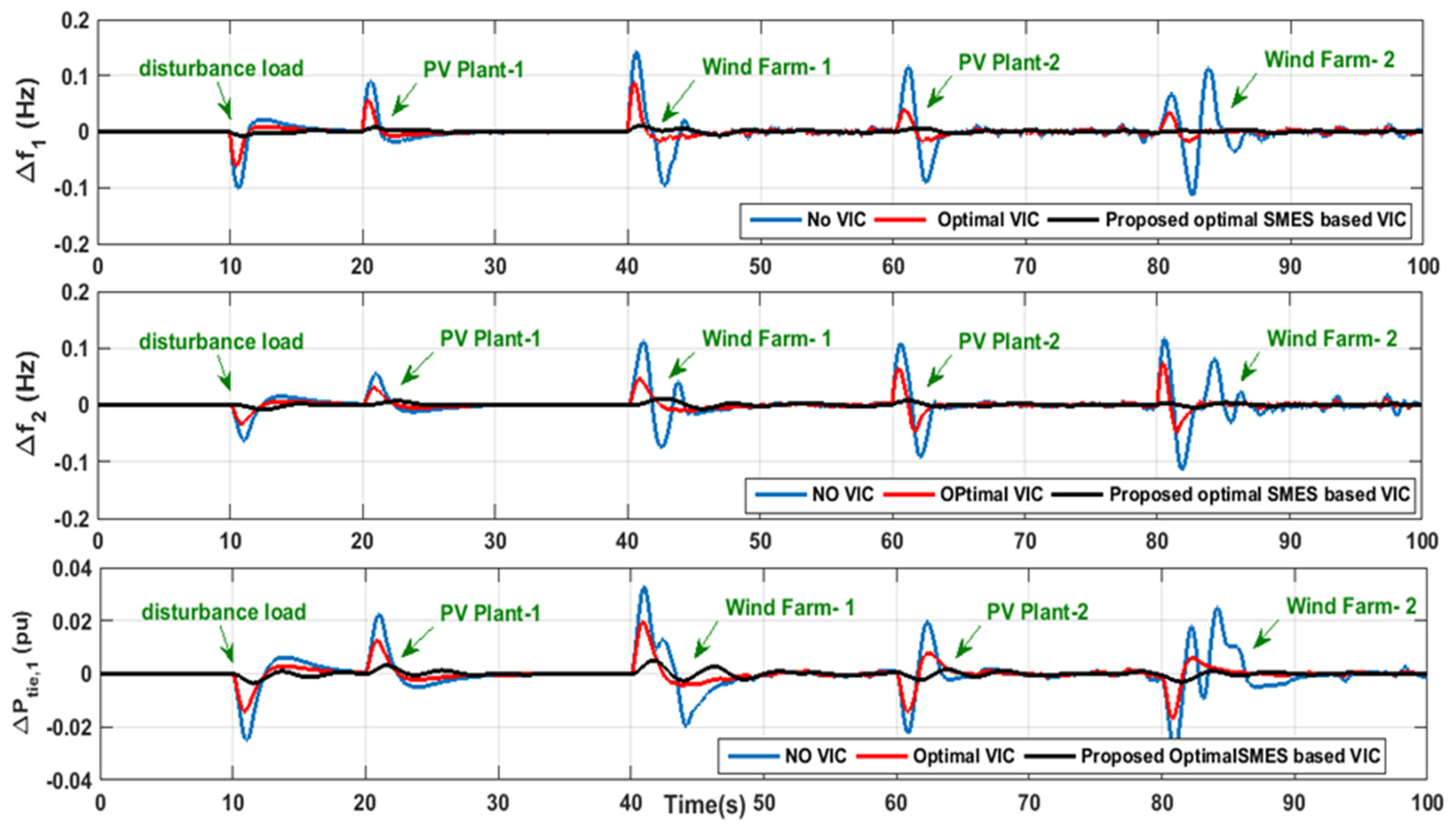
5.3. Scenario 3: Estimation of System Performance Considering High Renewables Power Penetration and Optimal VIC Based SMES Technology

The main aim of this situation is to evaluate the dependability of the investigated system with the proposed VIC based on SMES technology while taking into account RESs’ penetration levels and system uncertainties. The PID controller gains are the same gains obtained in the previous scenario to display the influence of the optimal traditional VIC-based on ESS devices as well as the optimal VIC based on SMES technology. In contrast to all other studies, this scenario introduces the selection of control parameters of the proposed VIC based on SMES technology. Furthermore, Table 6 lists the optimal parameters of the optimal gains of the VIC-based ESS devices and the optimal gains of the VIC-based SMES technology. Moreover, this scenario is divided into two cases to evaluate the robustness of the proposed control strategy (e.g., optimal PID controller based on the ISNS algorithm considering optimal control gains of VIC-based SMES technology).
Case A: In this case, the renewable penetration has been considered low, as shown in Figure 15a, where all sources (i.e., solar farms 1,2 and wind farms 1,2) have been started at the same time at t = 10 s, and a 5% SLP change at t = 50 s. Figure 17 depicts the system’s response to this case. It is clear that, during the increase of RESs’ penetration at t = 10 s, there are large frequency fluctuations in the case of no VIC, which makes the system unstable. However, there are fewer deviations in the case of optimal VIC-based ESS devices, which makes the system less stable. However, the response of the system with the considered optimal VIC-based SMES technology is very stable in comparison to other considered strategies. At that point, the proposed control strategy is able to suppress the fluctuations resulting from renewables penetration.
Case B: In this case, the renewable penetration has been considered high, as shown in Figure 15b. The operating condition of this case is similar to the operating conditions in Table 5. The system response for this case is displayed in Figure 18. Obviously, the proposed control strategy enhances the system performance in less time and does not influence the high renewable penetration in comparison to the system response based on traditional VIC-based ESS devices and no VIC.

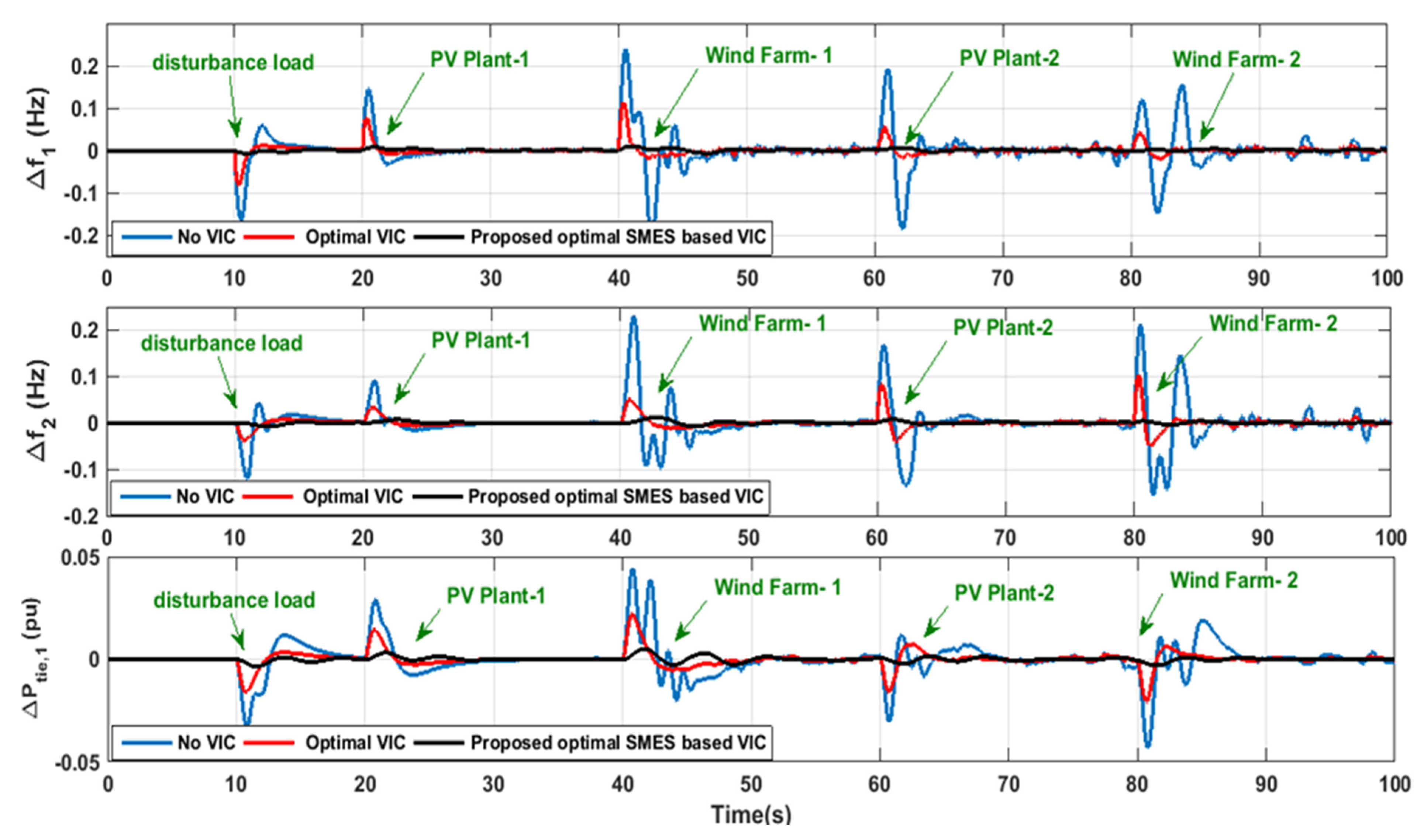
5.4. Scenario 4: Estimation of System Performance Considering High Renewables Power Penetration, Low of System Inertia, and Optimal VIC Based SMES Technology

The main objective of this scenario is to evaluate the reliability of the investigated system with the proposed VIC based on the SMES system while taking into account RESs’ penetration levels and system uncertainties and losses of system inertia. The losses of the system inertia are considered to be 50% from their nominal value. The operating conditions of this scenario are the same as have been considered in Table 5 considering high renewables penetration. Moreover, Figure 19 displays the system response of this scenario considering low system inertia. According to Figure 18, in case of no VIC, the frequency of the system fluctuates extremely due to the high renewables penetration and the loss of system inertia. Furthermore, by applying the traditional VIC-based ESS devices, the frequency fluctuates less and becomes in an acceptable range. However, the frequency becomes stable and all the system deviations can be robustly damped using the proposed optimal VIC-based SMES technology.

6. Conclusions

The conclusion of this study can be summarized in the following points:
  • An improved version of the SNS algorithm known as ISNS has been proposed to eliminate the demerits of the SNS algorithm (i.e., changing the exploration phase).
  • The superiority of the proposed ISNS algorithm has been validated by comparing its performance with conventional SNS, TSA, GWO, and WHO techniques based on a bench functions test.
  • According to the superiority of the ISNS algorithm, it has been applied to tune the PID controller parameters in a hybrid two area power system, considering system nonlinearities, high renewable power penetration, and load disturbance.
  • With the high renewable power penetration, the inertia of the system decreases and the instability problem occurs. An efficient control strategy based on optimal VIC based on SMES technology has been proposed to compensate for the losses in the system inertia.
  • Selecting the control gains of the proposed strategy based on the ISNS algorithm to improve the performance of the system effectively.
  • More than one scenario has been tested to validate the effectiveness of the proposed control strategy considering different operating conditions (i.e., low renewable power penetration, high renewable power penetration, losses of system inertia).
  • The system performance with the proposed strategy (e.g., optimal VIC based on SMES technology) has been improved by 50% and 90% compared to the systems based on the traditional optimal VIC-based ESS devices and the systems without VIC.

Author Contributions

Conceptualization, M.K., M.H.H. and S.K.; formal analysis, M.K., M.H.H. and S.K.; funding acquisition, M.K., M.H.H. and S.K.; investigation, M.K., M.H.H. and S.K.; methodology M.K. and S.K.; project administration, M.K. and M.H.H.; resources, S.K.; supervision, S.K.; validation, M.K. and M.F.E.; visualization, M.K. and M.H.H.; writing-original draft, M.K. and M.H.H.; writing-review and editing, M.F.E. and S.K. All authors have read and agreed to the published version of the manuscript.

Funding

This research is funded by Prince Sattam Bin Abdulaziz University, grant number IF-PSAU-2021/01/18921.

Acknowledgments

The authors extend their appreciation to the Deputyship for Research & Innovation, Ministry of Education in Saudi Arabia, for funding this research work through the project number (IF-PSAU-2021/01/18921).

Conflicts of Interest

The authors declare no conflict of interest.

Nomenclature

ESSEnergy storage system
SMESSuperconducting magnetic energy storage
VICVirtual inertia control
SCLSecondary control loop
ISNSImproved social network search algorithm
PIDProportional-integral derivative
VREVariable renewable energy
RESsRenewable energy sources
DTRDynamic thermal rating
LFCLoad frequency control
MPCModel predictive control
LAPOLightning attachment procedure optimization
VSGVirtual synchronous generators
GDBGovernor dead band
GRCGeneration rate constraint
PCSPower conditioning system
PSOParticle swarm optimizer
IAEIntegral Absolute Error
ITAEIntegral Time Weighted Absolute Error
ISEIntegral Square Error
ITSEIntegral Time Weighted Square Error
TSATunicate swarm algorithm
GWOGray wolf optimizer
WHOWild horse optimizer
Δ P m i The mechanical power deviation of area i
Δ P L i The load change of area i
Δ P t i e , i The deviations of the tie-line power among area-i,
Δ   P W T i The wind turbine’s output power of area i
Δ   P P V i The PV system’s output power of area i
T g i The governor’s time constant of area i
T t i The turbine’s time constant of area i
K h i The reheater gain of area i
T h i The time constant of the reheater of area i
R i The governor’s speed regulation of area i
Δ P c i The regulating of the system frequency of reheat power plant of the area i
T W T i The wind turbine time constant of area i
Δ P w i n d , i The wind power variation of area i
T   P V i The PV time constant of area i
Δ P s o l a r , i The solar power variation of area i
nThe number of the controlled area
T i j The synchronization time between two controlled areas
B i The area bias factor
A C E i The area control error of area i
T P i The power system’s time constant of area i
K P i The power system gain of area i
V d o The maximum circuit bridge voltage
I d The current flowing through the inductor
R c The damping resistor
Δ E D The inductor voltage deviations
K S M E S The control gain for the SMES loop
T D C The convertor time constant of the SMES
K I D The SMES feedback gain
Δ I D The inductor current deviation
LThe induction coil
X j The vector of the jth user’s view
X i The vector of the ith user’s view
X k The vector of the issue
AFThe admission factor
N r The group size
d The dth variable
n n e w d The new idea
x j d The current idea
kdThe derivative gain
kiThe integral gain
kpThe proportional gain
NThe derivative filter coefficient
JThe inertia gain
K I D , S M E S The SMES negative feedback gain

Appendix A

The parameter values of the studied two-area power system are listed as follows [40,43]:
R1 = R2 = 2.4 Hz/MW, T g 1   =   T g 2 = 0.08 s, T t 1   =   T t 2   = 0.3 s, K h 1   =   K h 2   = 0.5, T h 1   =   T h 2   = 10 s, K P 1   =   K P 2   = 10, T P 1 =   T P 2   = 20 s, B1 = B2 = 0.425 MW/Hz, T 12   = 0.086 s, K W T   = 1, T W T 1   =   T W T 2   = 1.5 s, K P V   = 1, T P V 1 =   T P V 2   = 1.85 s, α 12   = −1.

References

  1. Morales-España, G.; Nycander, E.; Sijm, J. Reducing CO2 emissions by curtailing renewables: Examples from optimal power system operation. Energy Econ. 2021, 99, 105277. [Google Scholar] [CrossRef]
  2. Joos, M.; Staffell, I. Short-term integration costs of variable renewable energy: Wind curtailment and balancing in Britain and Germany. Renew. Sustain. Energy Rev. 2018, 86, 45–65. [Google Scholar] [CrossRef]
  3. Gianfreda, A.; Parisio, L.; Pelagatti, M. A review of balancing costs in Italy before and after RES introduction. Renew. Sustain. Energy Rev. 2018, 91, 549–563. [Google Scholar] [CrossRef] [Green Version]
  4. Teh, J.; Lai, C.-M.; Cheng, Y.-H. Improving the Penetration of Wind Power with Dynamic Thermal Rating System, Static VAR Compensator and Multi-Objective Genetic Algorithm. Energies 2018, 11, 815. [Google Scholar] [CrossRef] [Green Version]
  5. Lai, C.-M.; Teh, J. Network topology optimisation based on dynamic thermal rating and battery storage systems for improved wind penetration and reliability. Appl. Energy 2022, 305, 117837. [Google Scholar] [CrossRef]
  6. Thrampoulidis, C.; Bose, S.; Hassibi, B. Optimal Placement of Distributed Energy Storage in Power Networks. IEEE Trans. Autom. Control. 2016, 61, 416–429. [Google Scholar] [CrossRef]
  7. Sidea, D.O.; Picioroaga, I.I.; Bulac, C. Optimal Battery Energy Storage System Scheduling Based on Mutation-Improved Grey Wolf Optimizer Using GPU-Accelerated Load Flow in Active Distribution Networks. IEEE Access 2021, 9, 13922–13937. [Google Scholar] [CrossRef]
  8. Ali, M.; Kotb, H.; AboRas, K.M.; Abbasy, N.H. Design of Cascaded PI-Fractional Order PID Controller for Improving the Frequency Response of Hybrid Microgrid System Using Gorilla Troops Optimizer; IEEE Access. Institute of Electrical and Electronics Engineers (IEEE): Piscataway, NJ, USA, 2021. [Google Scholar]
  9. Khadanga, R.K.; Kumar, A.; Panda, S. Frequency control in hybrid distributed power systems via type-2 fuzzy PID controller. IET Renew. Power Gener. 2021, 15, 1706–1723. [Google Scholar] [CrossRef]
  10. Zhang, H.; Liu, J.; Xu, S. H-Infinity Load Frequency Control of Networked Power Systems via an Event-Triggered Scheme. IEEE Trans. Ind. Electron. 2020, 67, 7104–7113. [Google Scholar] [CrossRef]
  11. Khamies, M.; Magdy, G.; Kamel, S.; Khan, B. Optimal Model Predictive and Linear Quadratic Gaussian Control for Frequency Stability of Power Systems Considering Wind Energy. IEEE Access 2021, 9, 116453–116474. [Google Scholar] [CrossRef]
  12. Shabib, G.; Mohamed, T.H.; Abrdelhameed, E.H.; Khamies, M. An Advanced Linear Quadratic Regulator For Load Frequency. In Proceedings of the 17th International Middle East Power Systems Conference, Mansoura, Egypt, 15–17 December 2015. [Google Scholar]
  13. Bengiamin, N.N.; Chan, W.C. Variable Structure Control of Electric Power Generation. IEEE Trans. Power Appar. Syst. 1982, PAS-101, 376–380. [Google Scholar] [CrossRef]
  14. Aoki, M. Control of large-scale dynamic systems by aggregation. IEEE Trans. Autom. Control. 1968, 13, 246–253. [Google Scholar] [CrossRef]
  15. Yousef, H.A.; L-Kharusi, K.A.; Albadi, M.H.; Hosseinzadeh, N. Load Frequency Control of a Multi-Area Power System: An Adaptive Fuzzy Logic Approach. IEEE Trans. Power Syst. 2014, 29, 1822–1830. [Google Scholar] [CrossRef]
  16. Akula, S.K.; Salehfar, H. Frequency Control in Microgrid Communities Using Neural Networks. In Proceedings of the North American Power Symposium (NAPS), Wichita, KS, USA, 13–15 October 2019. [Google Scholar]
  17. Khamies, M.; Magdy, G.; Hussein, M.E.; Banakhr, F.A.; Kamel, S. An Efficient Control Strategy for Enhancing Frequency Stability of Multi-Area Power System Considering High Wind Energy Penetration. IEEE Access 2020, 8, 140062–140078. [Google Scholar] [CrossRef]
  18. Khamies, M.; Magdy, G.; Kamel, S.; Elsayed, S.K. Slime Mould Algorithm for Frequency Controller Design of a Two-area Thermal-PV Power System. In Proceedings of the 2021 IEEE International Conference on Automation/XXIV Congress of the Chilean Association of Automatic Control (ICA-ACCA), Valparaíso, Chile, 22–26 March 2021. [Google Scholar]
  19. Elkasem, A.H.A.; Khamies, M.; Magdy, G.; Taha, I.B.M.; Kamel, S. Frequency Stability of AC/DC Interconnected Power Systems with Wind Energy Using Arithmetic Optimization Algorithm-Based Fuzzy-PID Controller. Sustainability 2021, 13, 12095. [Google Scholar] [CrossRef]
  20. Khamies, M.; Magdy, G.; Ebeed, M.; Kamel, S. A robust PID controller based on linear quadratic gaussian approach for improving frequency stability of power systems considering renewables. ISA Trans. 2021, 117, 118–138. [Google Scholar] [CrossRef] [PubMed]
  21. Khamies, M.; Magdy, G.; Selim, A.; Kamel, S. An improved Rao algorithm for frequency stability enhancement of nonlinear power system interconnected by AC/DC links with high renewables penetration. Neural Comput. Appl. 2021, 34, 2883–2911. [Google Scholar] [CrossRef]
  22. Nguyen, T.T.; Nguyen, T.T.; Duong, M.Q.; Doan, A.T. Optimal operation of transmission power networks by using improved stochastic fractal search algorithm. Neural Comput. Appl. 2019, 32, 9129–9164. [Google Scholar] [CrossRef]
  23. Tamrakar, U.; Shrestha, D.; Maharjan, M.; Bhattarai, B.; Hansen, T.; Tonkoski, R. Virtual Inertia: Current Trends and Future Directions. Appl. Sci. 2017, 7, 654. [Google Scholar] [CrossRef]
  24. Kerdphol, T.; Rahman, F.; Mitani, Y. Virtual Inertia Control Application to Enhance Frequency Stability of Interconnected Power Systems with High Renewable Energy Penetration. Energies 2018, 11, 981. [Google Scholar] [CrossRef] [Green Version]
  25. Kerdphol, T.; Rahman, F.S.; Watanabe, M.; Mitani, Y. Robust Virtual Inertia Control of a Low Inertia Microgrid Considering Frequency Measurement Effects. IEEE Access 2019, 7, 57550–57560. [Google Scholar] [CrossRef]
  26. Kerdphol, T.; Rahman, F.; Mitani, Y.; Hongesombut, K.; Küfeoğlu, S. Virtual Inertia Control-Based Model Predictive Control for Microgrid Frequency Stabilization Considering High Renewable Energy Integration. Sustainability 2017, 9, 773. [Google Scholar] [CrossRef] [Green Version]
  27. Kerdphol, T.; Watanabe, M.; Hongesombut, K.; Mitani, Y. Self-Adaptive Virtual Inertia Control-Based Fuzzy Logic to Improve Frequency Stability of Microgrid With High Renewable Penetration. IEEE Access 2019, 7, 76071–76083. [Google Scholar] [CrossRef]
  28. Kerdphol, T.; Rahman, F.S.; Mitani, Y.; Watanabe, M.; Küfeoǧlu, S.K. Robust Virtual Inertia Control of an Islanded Microgrid Considering High Penetration of Renewable Energy. IEEE Access 2018, 6, 625–636. [Google Scholar] [CrossRef]
  29. Kim, H.; Kang, J.; Shim, J.W.; Beerten, J.; Van Hertem, D.; Jung, H.J.; Kim, C.K.; Hur, K. Exploiting Redundant Energy of MMC–HVDC to Enhance Frequency Response of Low Inertia AC Grid. IEEE Access 2019, 7, 138485–138494. [Google Scholar] [CrossRef]
  30. Shi, R.; Zhang, X.; Hu, C.; Xu, H.; Gu, J.; Cao, W. Self-tuning virtual synchronous generator control for improving frequency stability in autonomous photovoltaic-diesel microgrids. J. Mod. Power Syst. Clean Energy 2017, 6, 482–494. [Google Scholar] [CrossRef] [Green Version]
  31. Li, X.; Chen, G. Stability enhancement strategy of virtual synchronous generator for cascaded multilevel converter based energy storage system under weak grid conditions. IET Renew. Power Gener. 2020, 14, 695–704. [Google Scholar] [CrossRef]
  32. Leng, D.; Polmai, S. Virtual Synchronous Generator Based on Hybrid Energy Storage System for PV Power Fluctuation Mitigation. Appl. Sci. 2019, 9, 5099. [Google Scholar] [CrossRef] [Green Version]
  33. Rehman, H.U.; Yan, X.; Abdelbaky, M.A.; Jan, M.U.; Iqbal, S. An advanced virtual synchronous generator control technique for frequency regulation of grid-connected PV system. Int. J. Electr. Power Energy Syst. 2021, 125, 106440. [Google Scholar] [CrossRef]
  34. Ali, M.H.; Wu, B.; Dougal, R.A. An Overview of SMES Applications in Power and Energy Systems. IEEE Trans. Sustain. Energy 2010, 1, 38–47. [Google Scholar] [CrossRef]
  35. Kerdphol, T.; Watanabe, M.; Mitani, Y.; Phunpeng, V. Applying Virtual Inertia Control Topology to SMES System for Frequency Stability Improvement of Low-Inertia Microgrids Driven by High Renewables. Energies 2019, 12, 3902. [Google Scholar] [CrossRef] [Green Version]
  36. Alam, S.; Alotaibi, M.A.; Alam, M.A.; Hossain, M.; Shafiullah, M.; Al-Ismail, F.S.; Rashid, M.U.; Abido, M.A. High-Level Renewable Energy Integrated System Frequency Control with SMES-Based Optimized Fractional Order Controller. Electronics 2021, 10, 511. [Google Scholar] [CrossRef]
  37. Kumar, N.; Alotaibi, M.A.; Singh, A.; Malik, H.; Nassar, M.E. Application of Fractional Order-PID Control Scheme in Automatic Generation Control of a Deregulated Power System in the Presence of SMES Unit. Mathematics 2022, 10, 521. [Google Scholar] [CrossRef]
  38. Kalyan, N.S.; Rao, G.S. Stabilizing Frequency and Voltage in Combined LFC and AVR System with Coordinated Performance of SMES and TCSC. In Control Applications in Modern Power System; Springer: Singapore, 2020; pp. 65–76. [Google Scholar]
  39. Kalyan, N.S.; Goud, B.S.; Reddy, C.; Bajaj, M.; Sharma, N.K.; Alhelou, H.H.; Siano, P.; Kamel, S. Comparative Performance Assessment of Different Energy Storage Devices in Combined LFC and AVR Analysis of Multi-Area Power System. Energies 2022, 5, 629. [Google Scholar] [CrossRef]
  40. Gozde, H.; Taplamacioglu, M.C.; Kocaarslan, I. Comparative performance analysis of Artificial Bee Colony algorithm in automatic generation control for interconnected reheat thermal power system. Electr. Power Energy Syst. 2012, 42, 167–178. [Google Scholar] [CrossRef]
  41. Hasanien, H.M. Whale optimisation algorithm for automatic generation control of interconnected modern power systems including renewable energy sources. IET Gener. Transm. Distrib. 2018, 12, 607–614. [Google Scholar] [CrossRef]
  42. Hasanien, H.M.; El-Fergany, A. Salp swarm algorithm-based optimal load frequency control of hybrid renewable power systems with communication delay and excitation cross-coupling effect. Electr. Power Syst. Res. 2019, 176, 1–10. [Google Scholar] [CrossRef]
  43. Hasanien, H.M.; El-Fergany, A.A. Symbiotic organisms search algorithm for automatic generation control of interconnected power systems including wind farms. IET Gener. Transm. Distrib. 2017, 11, 1692–1700. [Google Scholar] [CrossRef]
  44. Elmelegi, A.; Mohamed, E.A.; Aly, M.; Ahmed, E.M.; Mohamed, A.-A.A.; Elbaksawi, O. Optimized Tilt Fractional Order Cooperative Controllers for Preserving Frequency Stability in Renewable Energy-Based Power Systems. IEEE Access 2021, 9, 8261–8277. [Google Scholar] [CrossRef]
  45. Mohamed, E.A.; Ahmed, E.M.; Elmelegi, A.; Aly, M.; Elbaksawi, O.; Mohamed, A.-A.A. An Optimized Hybrid Fractional Order Controller for Frequency Regulation in Multi-Area Power Systems. IEEE Access 2021, 8, 213899–213915. [Google Scholar] [CrossRef]
  46. Lotfy, M.; Senjyu, T.; Farahat, M.; Abdel-Gawad, A.; Yona, A. A Frequency Control Approach for Hybrid Power System Using Multi-Objective Optimization. Energies 2017, 10, 80. [Google Scholar] [CrossRef] [Green Version]
  47. Amrouche, S.O.; Rekioua, D.; Rekioua, T.; Bacha, S. Overview of energy storage in renewable energy systems. Int. J. Hydrog. Energy 2016, 41, 20914–20927. [Google Scholar] [CrossRef]
  48. Khosraviani, M.; Jahanshahi, M.; Farahani, M.; Bidaki, A.R.Z. Load–Frequency Control Using Multi-objective Genetic Algorithm and Hybrid Sliding Mode Control-Based SMES. Int. J. Fuzzy Syst. 2017, 20, 280–294. [Google Scholar] [CrossRef]
  49. Eberhart, R.; Kennedy, J. A new optimizer using particle swarm theory. In Proceedings of the Sixth International Symposium on Micro Machine and Human Science, Nagoya, Japan, 4–6 October 1995. [Google Scholar]
  50. Kaur, S.; Awasthi, L.K.; Sangal, A.L.; Dhiman, G. Tunicate Swarm Algorithm: A new bio-inspired based metaheuristic paradigm for global optimization. In Engineering Applications of Artificial Intelligence; Elsevier BV: Amsterdam, The Netherlands, 2020; Volume 90, p. 103541. [Google Scholar]
  51. Mirjalili, S.; Mirjalili, S.M.; Lewis, A. Grey Wolf Optimizer. Adv. Eng. Softw. 2014, 69, 46–61. [Google Scholar] [CrossRef] [Green Version]
  52. Naruei, I.; Keynia, F. Wild horse optimizer: A new meta-heuristic algorithm for solving engineering optimization problems. In Engineering with Computers; Springer Science and Business Media LLC: Berlin, Germany, 2021. [Google Scholar]
  53. Abd-Elazim, S.M.; Ali, E.S. BFOA based design of PID controller for two area Load Frequency Control with nonlinearities. Electr. Power Energy Syst. 2013, 51, 224–231. [Google Scholar]
  54. Sahu, R.K.; Panda, S.; Padhan, S. A hybrid firefly algorithm and pattern search technique for automatic generation control of multi area power systems. Electr. Power Energy Syst. 2015, 64, 9–23. [Google Scholar] [CrossRef]
Figure 1. A schematic representation of the system under consideration.
Mathematics 10 01584 g001
Figure 2. The simplified block diagram of the system under consideration.
Mathematics 10 01584 g002
Figure 3. The dynamic model of inertia control-based energy storage devices.
Mathematics 10 01584 g003
Figure 4. The SMES’s basic form.
Mathematics 10 01584 g004
Figure 5. The dynamic model of SMES for frequency stability.
Mathematics 10 01584 g005
Figure 6. The dynamic model of VIC-based SMES technology.
Mathematics 10 01584 g006
Figure 7. A general form of a social network.
Mathematics 10 01584 g007
Figure 8. The flowchart of the ISNS algorithm.
Mathematics 10 01584 g008
Figure 9. The process of selecting the optimal parameters of the proposed control strategy.
Mathematics 10 01584 g009
Figure 10. Qualitative metrics of nine benchmark functions: 2D views of the functions, search history, average fitness history, and convergence curve using ISNS algorithm.
Mathematics 10 01584 g010aMathematics 10 01584 g010b
Figure 11. The convergence curves of all algorithms for 23 benchmark functions.
Mathematics 10 01584 g011aMathematics 10 01584 g011b
Figure 12. Boxplots for all algorithms for 23 benchmark functions.
Mathematics 10 01584 g012aMathematics 10 01584 g012b
Figure 13. The convergence cure of the PID controller based on (SNS, and ISNS) algorithms.
Mathematics 10 01584 g013
Figure 14. The system under consideration performance for scenario 1.
Mathematics 10 01584 g014
Figure 15. (a). The output of PV farm and wind farm in case of low renewables penetration. (b). The output of PV farm and wind farm in case of low renewables penetration.
Mathematics 10 01584 g015
Figure 16. The system under consideration performance for scenario 2.
Mathematics 10 01584 g016
Figure 17. The system under consideration performance for case A, scenario 3.
Mathematics 10 01584 g017
Figure 18. The system under consideration performance for case B, scenario 3.
Mathematics 10 01584 g018
Figure 19. The system under consideration performance for scenario 4.
Mathematics 10 01584 g019
Table 1. The statistical results of benchmark functions using the proposed ISNS technique and other recent techniques.
FunctionISNSSNSTSA [50] GWO [51] WHO [52]
F1Best9.21 × 10−381.03 × 10−283.79 × 10−86.34 × 10−125.08 × 10⁻²¹
Mean4.39 × 10−371.37 × 10−274.64 × 10−73.13 × 10−112.13 × 10⁻¹⁸
Median2.66 × 10−374.77 × 10−281.17 × 10−72.43 × 10−116.47 × 10⁻¹⁹
Worst1.44 × 10−361.04 × 10−264.09 × 10−67.40 × 10−118.56 × 10⁻¹⁸
std4.35 × 10−372.38 × 10−271.15 × 10−62.26 × 10−112.98 × 10⁻¹⁸
F2Best8.57 × 10−202.3 × 10−152.44 × 10−61.42 × 10−74.13 × 10⁻¹³
Mean2.95 × 10−195.64 × 10−151.9 × 10−52.77 × 10−71.3 × 10⁻¹⁰
Median2.72 × 10−194.21 × 10−151.86 × 10−52.66 × 10−75.29 × 10⁻¹¹
Worst5.17 × 10−191.4 × 10−143.68 × 10−54.78 × 10−76.34 × 10⁻¹⁰
std1.28 × 10−193.51 × 10−159.44 × 10−69.9 × 10−81.77 × 10⁻¹⁰
F3Best8.11 × 10−269.18 × 10−130.0276080.0084625.13 × 10−13
Mean1.5 × 10−234.18 × 10−081.1226770.6104411.2 × 10−8
Median3.82 × 10−244.13 × 10−090.7721950.1854126.29 × 10−11
Worst8.29 × 10−233.9 × 10−073.9146953.5670092.3 × 10−7
std2.22 × 10−239.17 × 10−081.0963130.8271155.14 × 10−8
F4Best3.51 × 10−181.33 × 10−130.675310.0026085.11 × 10−9
Mean8.52 × 10−185.45 × 10−133.6166540.0083.5 × 10−7
Median8.26 × 10−184.09 × 10−133.0222530.0070921 × 10−7
Worst1.53 × 10−181.87 × 10−129.3615160.0166672.14 × 10−6
std3.27 × 10−184.55 × 10−132.3436580.0038456.09 × 10−7
F5Best27.4914727.664427.1897325.9251526.68451
Mean27.9592628.0339939.0109427.1890337.10656
Median27.931427.9798428.6620327.0981427.67985
Worst28.4163128.44604239.778528.79035208.5133
std0.2727320.21687347.263390.7218240.37046
F6Best0.095320.0808792.8869970.2522540.013248
Mean0.1942320.2922413.8007190.6475540.064784
Median0.1886880.2551153.7369350.6113780.058665
Worst0.3482260.758424.8503711.1727570.16971
std0.0753470.1816960.5278510.2808880.043941
F7Best0.0001590.0001680.0076040.0014770.000605
Mean0.0007120.0007080.0192060.0044330.001779
Median0.000510.0006880.0184790.0036850.001387
Worst0.0026480.0021870.044360.010330.004938
std0.0006120.0004880.0076280.0025540.001255
F8Best−11713.3−7613.49−1394.45−1495.31−1807.46
Mean−10512.5−6358.62−1212.82−1245.57−1721.44
Median−10551.2−6324.46−1232.52−1224.18−1729.69
Worst−9365.68−5562.96−976.635−1123.85−1630.81
std587.7064538.2484122.0762104.015354.13894
F9Best0.000.00156.6671.0624670.00
Mean0.000.00228.01779.8010181.11 × 10−5
Median0.000.00228.6349.8247131 × 10−9
Worst0.000.00331.758124.969680.000177
std0.000.0046.409195.5658123.96 × 10−5
F10Best4.44 × 10−154.44 × 10−1520.8113320.764878.88 × 10−16
Mean4.44 × 10−157.46 × 10−1520.960820.923441.003597
Median4.44 × 10−156.22 × 10−1520.9935620.944657.99 × 10−6
Worst4.44 × 10−151.51 × 10−1421.096121.0630920.01369
std0.003.69 × 10−150.0915050.0834334.474524
F11Best0.000.001.3 × 10−96.56 × 10−130.00
Mean0.000.000.0070180.0098911.83 × 10−16
Median0.000.001.44 × 10−84.55 × 10−120.00
Worst0.000.000.0291260.0554073.66 × 10−15
std0.000.000.0102430.0157668.19 × 10−16
F12Best0.0003620.0006960.3749560.0060664.64 × 10−5
Mean0.0012040.002682.8058890.0261510.026544
Median0.0009480.002842.0098330.0234740.000309
Worst0.003250.0048937.6568630.0471760.207386
std0.0007920.0012322.1289360.0134140.056802
F13Best0.003460.0575192.3722950.099550.011802
Mean0.0338940.1543853.2980850.6138320.173897
Median0.0292590.1403233.228760.6099810.136817
Worst0.0693410.3786724.160731.0440.700833
std0.0205990.0776590.5658350.2800290.157716
F14Best0.9980040.9980040.9980040.9980040.998004
Mean0.9980040.9980048.2986833.8921061.097209
Median0.9980040.99800410.763182.9821050.998004
Worst0.9980040.99800418.3043112.670512.982105
std0.001.02 × 10−165.5339523.7276810.443659
F15Best0.0003070.0003080.0003080.000310.000307
Mean0.0003070.000350.0071360.0035470.000602
Median0.0003070.0003130.0005050.0005460.000593
Worst0.0003070.0005820.0316990.0203630.001223
std1.99 × 10−196.8 × 10−50.0106060.0072550.000286
F16Best−1.03163−1.03163−1.03163−1.03163−1.03163
Mean−1.03163−1.03163−1.0253−1.03158−1.03163
Median−1.03163−1.03163−1.03163−1.03163−1.03163
Worst−1.03163−1.03163−0.99999−1.03063−1.03163
std2.22 × 10−161.53 × 10−160.0129810.0002235.09 × 10−17
F17Best0.3978870.3978870.397890.3978880.397887
Mean0.3978870.3978870.3979270.3978910.397887
Median0.3978870.3978870.3979070.3978910.397887
Worst0.3978870.3978870.3980820.3978970.397887
std0.000.004.53 × 10−53.01 × 10−60.00
F18Best3.003.003.0000093.003.00
Mean3.003.008.4000783.0000683.00
Median3.003.003.0000843.0000363.00
Worst3.003.0084.000013.0002383.00
std1.17 × 10−151.6 × 10−1518.787996.53 × 10−51.13 × 10⁻¹⁵
F19Best−3.86278−3.86278−0.30048−0.30048−0.30048
Mean−3.86278−3.86278−0.30048−0.30048−0.30048
Median−3.86278−3.86278−0.30048−0.30048−0.30048
Worst−3.86278−3.86278−0.30048−0.30048−0.30048
std2.28 × 10−152.22 × 10−151.14 × 10−161.14 × 10−161.14 × 10⁻¹⁶
F20Best−3.322−3.322−3.32148−3.32198−3.322
Mean−3.2566−3.29822−3.07223−3.22876−3.21756
Median−3.2031−3.322−3.20118−3.26239−3.322
Worst−3.2031−3.2031−0.20816−2.84039−2.43178
std0.0606850.0487930.6793210.1255580.239908
F21Best−10.1532−10.1532−10.0895−10.1502−10.1532
Mean−10.1532−10.1532−5.89545−8.51218−9.77706
Median−10.1532−10.1532−4.90994−10.1413−10.1532
Worst−10.1532−10.1532−2.58642−2.62918−2.63047
std3.21 × 10−152.8 × 10−122.7751112.9631531.682133
F22Best−10.4029−10.4029−10.3637−10.4024−10.4029
Mean−10.4029−10.4029−7.02119−10.0134−9.75463
Median−10.4029−10.4029−9.8942−10.3959−10.4029
Worst−10.4029−10.4029−1.82478−2.76526−2.75193
std3.36 × 10−155.02 × 10−153.570711.7060422.031123
F23Best−10.5364−10.5364−10.4599−10.5348−10.5364
Mean−10.5364−10.5364−5.50502−9.74305−10.5364
Median−10.5364−10.5364−2.83596−10.5274−10.5364
Worst−10.5364−10.5364−1.66783−2.42135−10.5364
std4.12 × 10−82 × 10−153.7281972.4184641.58 × 10−15
Table 2. The optimal parameters of the PID controller based on SNS and ISNS algorithms.
Controller Area K p K i K d N
PID based SNSarea-10.63290.71540.3378100
area-20.40780.00940.36685100
PID based
ISNS
area-10.99980.71930.5346100
area-20.02300.00010.3335100
Table 3. The performance indices for PID controllers based different optimization algorithms.
ControllerObjective Function Value (ITAE)
PID based ZN [53]0.6040
PID based GA [53]0.5513
PID based BFOA [53]0.4788
PID based FA [54]0.3240
PID based hFA-PS [54]0.2789
PID based SNS0.19248
PID based ISNS0.18951
Table 4. Optimal parameters of PID controller parameters considering RESs penetration.
PID Area K p K i K d N
PID for area19.977243.83567.2524399.0354
PID for area29.999729.730732.9444699.2726
Table 5. The operating conditions of the system under study for scenario 2.
Source Area Start Time (s)End Time (s)
Solar farm-1Area-120100
wind farm-1Area-140100
Solar farm-2Area-260100
wind farm-2Area-280100
Load disturbanceArea-110100
Table 6. The optimal parameters for VIC considering ESS devices and SMES technology.
Control Strategy ParametersArea-1Area-2
Optimal VIC based ESS devices K v 33
Optimal VIC based SMES technology K v 1.35800.1759
K I D 0.02160.0150
K S M E S 0.11521.6677
Publisher’s Note: MDPI stays neutral with regard to jurisdictional claims in published maps and institutional affiliations.

