Article

Artificial Neural Based Speed and Flux Estimators for Induction Machine Drives with Matlab/Simulink

1
Electrical Engineering Department, Faculty of Engineering, Minia University, Minia 61511, Egypt
2
Department of Electric Drive and Automation of Industrial Installations, Novosibirsk State Technical University, 630000 Novosibirsk, Russia
3
Department of Computer, College of Science and Arts in Ar Rass, Qassim University, Ar Rass 58613, Saudi Arabia
4
College of Engineering at Wadi Addawasir, Prince Sattam bin Abdulaziz University, Wadi Addawasir 11991, Saudi Arabia
5
Electrical Engineering Department, Faculty of Engineering, Aswan University, Aswan 81542, Egypt
*
Author to whom correspondence should be addressed.
Mathematics 2022, 10(8), 1348; https://doi.org/10.3390/math10081348
Submission received: 22 February 2022 / Revised: 2 April 2022 / Accepted: 13 April 2022 / Published: 18 April 2022
(This article belongs to the Special Issue Modeling and Simulation of Control System)

Abstract

:
In this paper, an Artificial Neural Network (ANN) for accurate estimation of the speed and flux for induction motor (IM) drives has been presented for industrial applications such as electric vehicles (EVs). Two ANN estimators have been designed, one for the rotor speed estimation and the other for the stator and rotor flux estimation. The input training data has been collected based on the currents and voltage data, while the output training data of the speed and stator and rotor fluxes has been established based on the measured speed and flux estimator-based mathematical model of the IM. The designed ANN estimators can overcome the problem of the parameter’s variations and drift integration problems. Matlab/Simulink has been used to develop and test the ANN estimators. The results prove the ANN estimators’ effectiveness under various operation conditions.

1. Introduction

In recent years, the principle of vector-control for induction motors (IMs) has become very popular since the ability to control precise motor torque enables high-performance motor drive systems to be designed, such as electric vehicles (EVs) [1,2,3,4]. In conjunction with the low cost and ease of maintenance due to the robustness of the structure, reliability, and high-performance of the IM, this has led to replacing direct current (DC) machines with IMs in many applications in the last few years. Such advantages have determined the significant creation of electrical drives for all relevant aspects, with the IM as the execution component: starting, braking, speed-reversal, and speed change [2]. AC drives require extensive advanced control techniques, often more expensive but more reliable [5].
Dynamic operation of the IM drive plays an important role in the general system performance [6,7]. In many IM applications, vector-control is the most widely used technique owing to its high rendering for controlling IMs [8]. The vector-control theory for IMs, is based on acquiring the phase and magnitude of voltages or currents. That control is carried out based on the transformations of Clarke and Park, which are responsible for producing torque and flux, respectively. IMs works like a separately excited DC-motor in which two independent orthogonal variables control the torque and flux, namely armature and field currents, respectively [4,9]. This characteristic leads to an unfavorable coupling of electromagnetic torque and flux, resulting in the complexity and difficulty of using IM controllers. Via field-oriented control (FOC), this issue would be solved. The basic concept of vector control is that the torque and flux are regulated in a separable manner through vector control, and the action of a DC-motor is reproducing. The most direct way of achieving field orientation is to split the stator current into two appropriate elements and control them separately. The first element is selected to generate an MMF wave spatially in phase with the rotor-flux-density; this element is related directly to the rotor-flux-amplitude and is the flux-producing-current component. Also, the second element is selected for generating the MMF wave spatially in quadrature with rotor-flux-density; this element is equivalent to motor torque and is referred to as a torque-producing-current component.
Blaschke and Hasse proposed the FOC-based direct field orientation control (DFOC) [7,10]. With DFOC, two Hall-effect sensors are mounting in the air-gap to get rotor flux based on air-gap measurements. The DFOC’s block diagram for the IM drive is displayed in Figure 1. Since it is impracticable to sense rotor flux directly, some rotor-flux-orientation (RFO) computation has to be done for extracting the desirable information from a directly sensed signal. The essence of these computations for terminal voltage and current sensing is demonstrated in Figure 1. The stator and rotor resistance variation may affect the performance of the DFOC method at low speed. There is an undesirable dip in speed at the instant of resistance deviation, but the restoring time of this dip occurs in a short time. The rotor-flux amplitude rises to compensate for the excess voltage drops on the stator and rotor windings. In general, DFOC offers poor dynamic performance when stator and rotor resistance increase [11,12,13].
Most of the reported references concluded that the implementation of the rotational transducers for establishing the speed feedback loop for high dynamic AC drives results in reliability reduction and raises the system cost and implementation. Many sensorless schemes have been introduced in the literature. In the most introduced schemes, the sensitivity to parameter variations, especially the stator resistance, affects the precision of the estimation at a low speed [7,14,15,16]. The estimation process may suffer instability at a certain speed region, especially at low speeds.
The process of flux estimation is an essential assignment to implement IM drives accurately. The flux estimation is generally based on the currents and voltages associated with the machine models. Problems such as pure integrations, draft, and initial conditions may affect the performance and accurate flux estimation [17]. Other issues may be considered based on the possibility of parameter uncertainty. These problems may be solved by applying the low-pass filter, which may overcome the problem of initial conditions and the DC offset of the integration but in a narrow speed range. Parameter estimations, especially the stator resistance, may improve the estimation process at low-speed ranges by increasing the implementation time and cost [7,14,15,16].
Many control schemes using artificial neural networks have been applied to enhance the performance of AC drives [1,2,5,9,14,15,18,19,20]. Moreover, the mathematical model-based control systems may result in low dynamic performance and suffer from parameter variation dependency [17]. So, applying ANN-based schemes can overcome the disadvantages of mathematical model-based control systems. ANNs can introduce many advantages for improving the performance with error tolerance [11,18,21].
ANN has been introduced to overcome the mentioned problems for flux estimation, but the estimator still needs the rotor speed [17]. In Ref. [18], the motor speed has been measured using speed sensors which reduce the system’s reliability and increase the cost of the drive system. The elimination of the speed sensor has been presented with reducing the accuracy of the flux estimation in [5,12,16]. ANNs have been utilized in many industrial applications; for example, in [22], ANNs were applied considering the measured data to introduce a model of magnetorheological fluids’ relative magnetic permeability. The reported results show the effectiveness of the introduced neural network approaches considering a reduced parameters model [22].
In this paper, to improve the reliability of the flux estimator with the elimination of the speed sensor, two ANN estimators have been designed and implemented. The first is a speed estimator based on the voltage and current measurements. The other one is for flux estimator considering its inputs as the currents and voltages measurements as well as the estimated speed from the first one. ANN-based estimators can overcome the drift problem of pure integrators and enhance the robustness of stator resistance variations. Offline training of the two ANNs has been used to save implementation time. The validation of the overall control scheme with the two ANNs has been achieved using Matlab/Simulink simulation of the IM drive in different operation conditions. The same methodology can be applied for other machine drives and industrial applications.
The article is developed as follows: Section two illustrates the mathematical model of induction motor. The field-oriented vector control of IM has been introduced in Section 3. The methodology of implementing ANN-based speed and flux estimator has been presented in Section 4. The ANN-based speed estimator has been introduced in Section 5. The ANN-based flux estimator has been described in Section 6. The numeric results and discussions are executed in Section 7. The last section contributes to the conclusion of the proposed work.

2. Mathematical Model of Induction Motor

The mathematical model of induction motor can be represented in the stationary reference frame ( α β ) as follows [6]:
p [ i s   λ r ] = [ A 11 A 12 A 21 A 22 ] [ i s λ r ] + [ B 0 ] u s ,
i s = C . [ i s λ r ]
where i s = [ i α s i β s ] T , λ r = [ λ α r λ β r ] T , µ s = [ V α s V β s ] T , .
Matrices elements of A 11 , A 12 , A 21 , and A 22 can be defined as the following:
A 11 = { ( R s σ L s + 1 σ σ T r )   } I , A 12 = { L m σ L s L r T r } I { L m σ L s L r ω r } J , A 21 = ( L m T r ) I ,   and A 22 = ( 1 T r )   I + ω r J .
The reset matrices elements of Equation (2) can be represented as:
B = ( 1 σ L s ) I C = [ I 0 ] , and I , J denote unit and skew symmetric matrices respectively and can be defined as, I = [ 1 0 0 1 ] , J = [ 0 1 1 0 ] .
The electromagnetic torque can be represented as:
T e = k t ( λ dr i qs λ qr i ds ) .
The rotor speed ω r can be defined as follows:
p ω r = 1 J m ( T e f d ω r T l )
where k t = 3 P L m 2 L r . L m , L r , and L s denote magnetizing, rotor self-leakage, and stator self-leakage inductances (H), p denotes d / d t , σ denotes the leakage coefficient and is defined as ( 1 L m 2 L s L r ) and T r = L r R r . Moreover, T l and T e denote load and electromagnetic torques (Nm), R s , R r denote the stator and rotor resistances (Ω), f d denotes friction coefficient and J m denotes a moment of inertia (kg·m2).

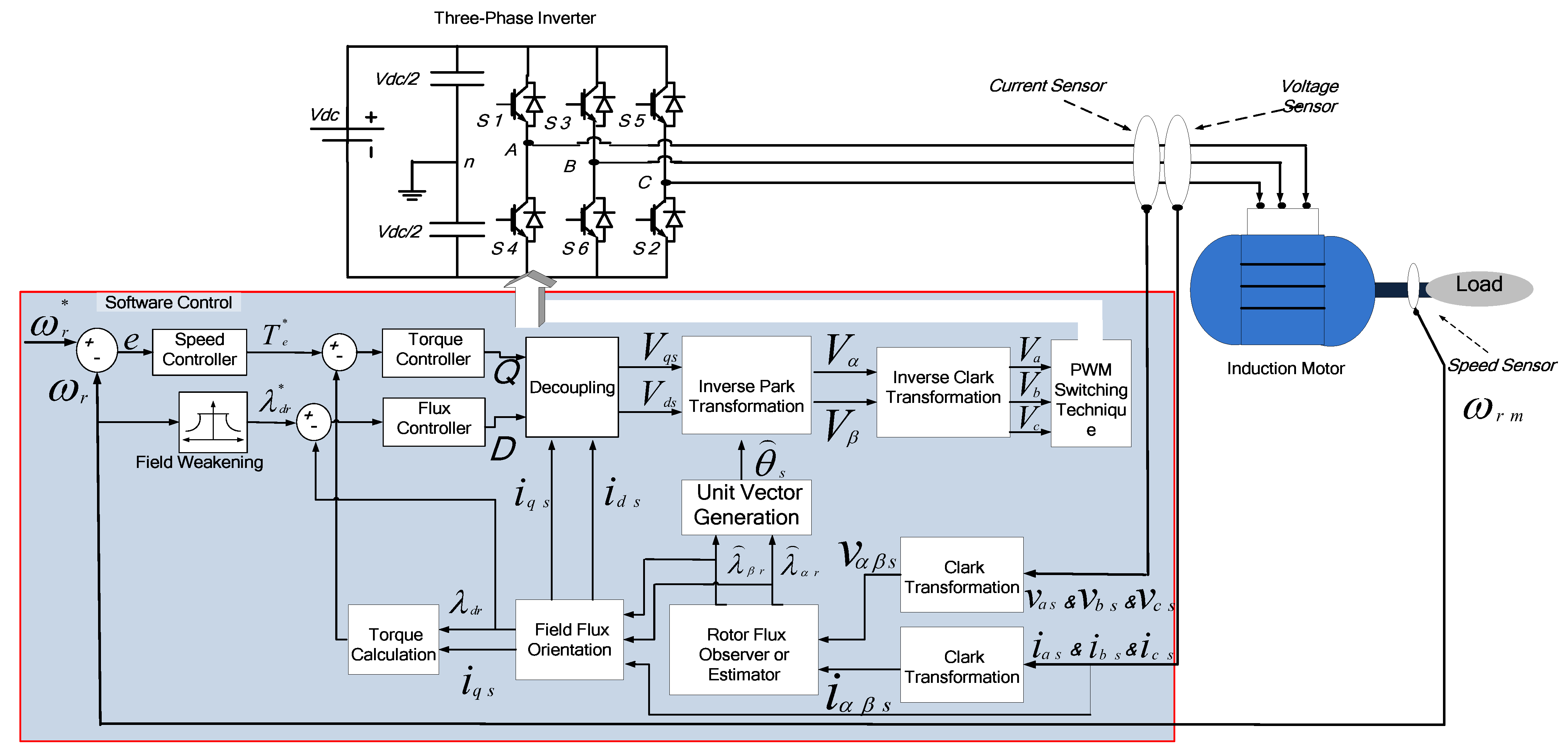
3. Field-Orientation Control Scheme of IM

The field-orientation control can be defined in the d q synchronous reference frame. The basic of the FOC is based on controlling the rotor flux to be in d a x i s while the q a x i s component equal to zero. Moreover, the rotor flux λ r can be written as follows [2,7]:
λ r = L m i d s *
where   i d s and   i q s     are orthogonal components of the stator currents in the d q axis, and the slip-speed ω s l can be controlled as follows:
ω s l = s ω s = ( ω s ω r ) = R r L r i q s * i d s * = L m T r i q s * λ r
where, T r denotes the rotor time constant and the superscript   * denotes the reference value.
The electromagnetic torque is stated considering the peak phasor values of i d s and   i q s   as follows:
T e = 3 P L m 2 L r λ r i q s = 3 P L m 2 2 L r i d s i q s  
where P is the pair-pole-number and λ r is the rotor flux.
The electromagnetic torque can be expressed as:
T e = 3 2 P L m ( i q s i d r i d s i q r )
The rotor-flux-linkages are stated by:
L m ( i q s + i q r ) + L r i q r = λ q r   and
L m ( i d s + i d r ) + L r i d r = λ d r
The rotor equations in terms of the rotor-flux-linkages are:
R r i q r + p λ q r + s ω s λ d r = 0 ,   and
R r i d r + p λ d r s ω s λ q r = 0
With the application of FOC principle, the rotor-flux-space vector’s q a x i s component will always remain zero. So, the rotor flux can be written as follows:
λ r = { λ d r λ q r = p λ q r = 0
Therefore, the rotor circuit in Equation (7) can be stated as:
R r i q r + s ω s λ r = 0   and   R r i d r + p λ r = 0
Consequently, the rotor currents in Equation (8) would be written as:
i q r = L m L m + L r i q s   and   i d r = λ r L m + L r L m L m + L r i d s
Generating the reference values of the stator current components i q s * and   i d s * can be obtained using the torque-command T e * and rotor-flux-command λ r * values as:
i q s * = 1 K t T e * λ r *   and   i d s * = 1 L m ( 1 + T r p ) λ r *
where K t = 3 P L m 2 L r , T r is the rotor-time constant, and p is a differential operator. T e * is the output of the speed controller.

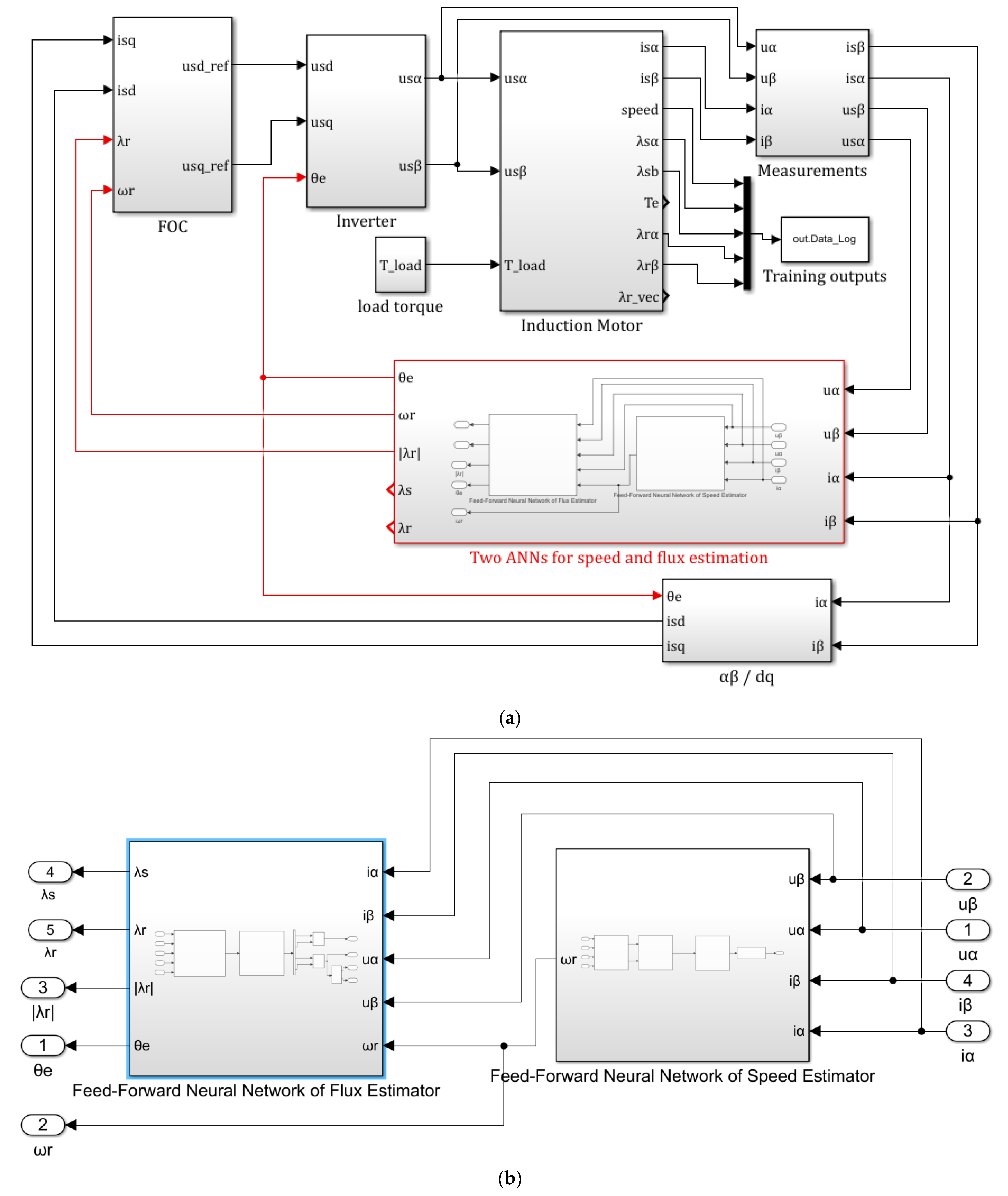
4. Methodology of ANN Application for Speed and Flux Estimation

Implementing the ANNs speed and flux estimators has the training, testing, and validation stages. This section presents the methodology of the design and implementation of the two parallel ANNs.

4.1. Step 1. Collecting Training Data

The training data has been collected by simulation of the direct vector control scheme of Figure 1. The collected data has been achieved by assuming random reference speed and load torque, as shown in Figure 2. The collected data are the measured voltages and currents in α β . Also, the actual rotor speed has been logged. The data has been saved and exported for training the ANN.
Figure 3 shows the reference speed, which is assumed to be changed over the simulation time. Moreover, the figure shows that the assumed load torque disturbance has been randomly changed with the speed variation. The speed and load torque have been assumed to cover a wide range of operating conditions. The simulation time is 250 s. The simulation has been done with a step time of 5 × 10⁻³. So, the size of data points is 50,000 points. Moreover, 25 starting points have been removed from the data set.
Measurement noise has been injected into the measured signals. The variations of the flux amplitude have been enforced for enriching the learning set. A variation in the stator resistance has been assumed. Moreover, noise in the measured speed has been added to enhance the feed-forward neural network (FFNN) robustness against noise. Figure 3 shows the imposed noise for rotor and stator fluxes, rotor speed, stator currents, and stator resistance. Parameters and data specifications of the tested induction motor have been reported in Table A1.

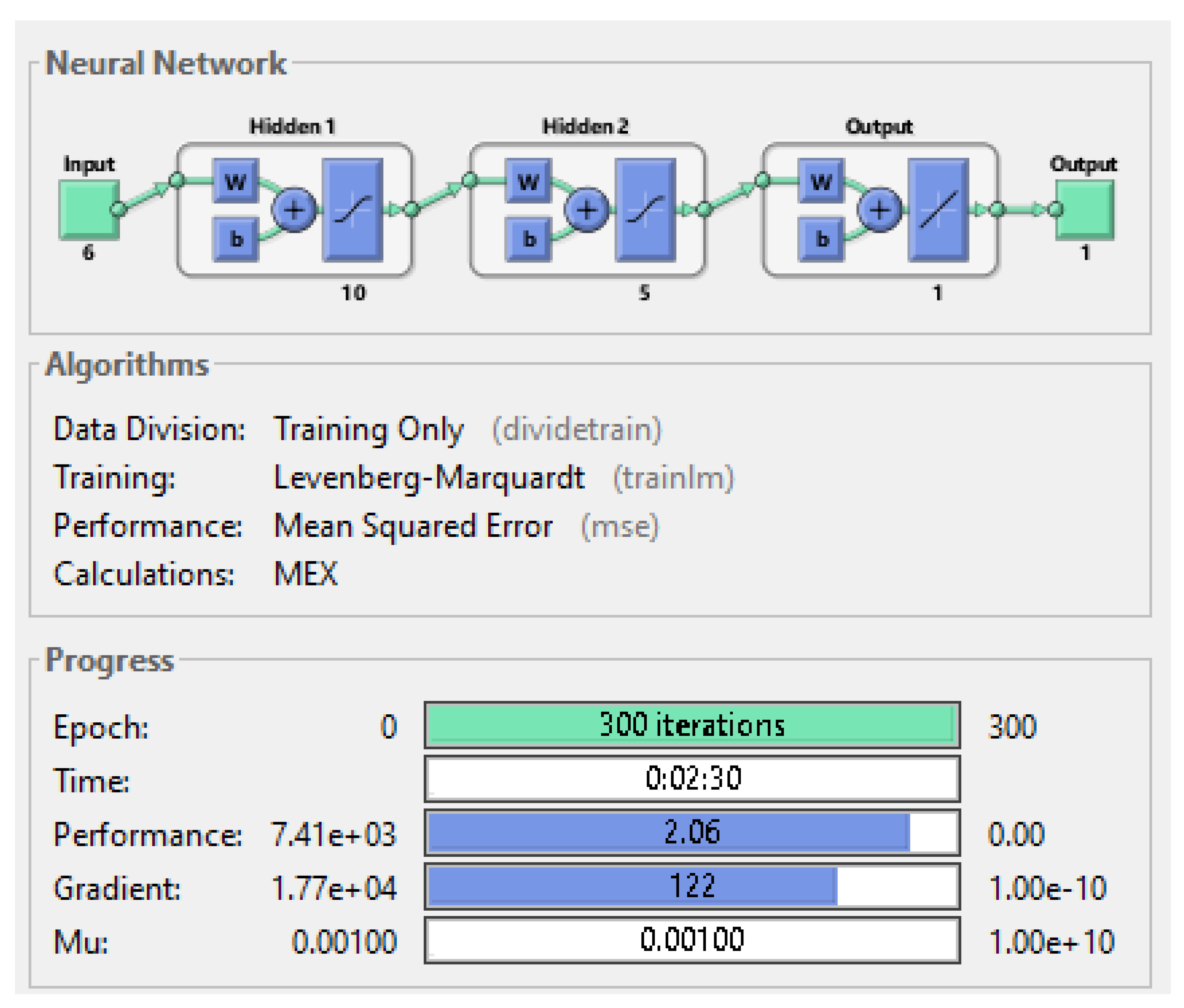
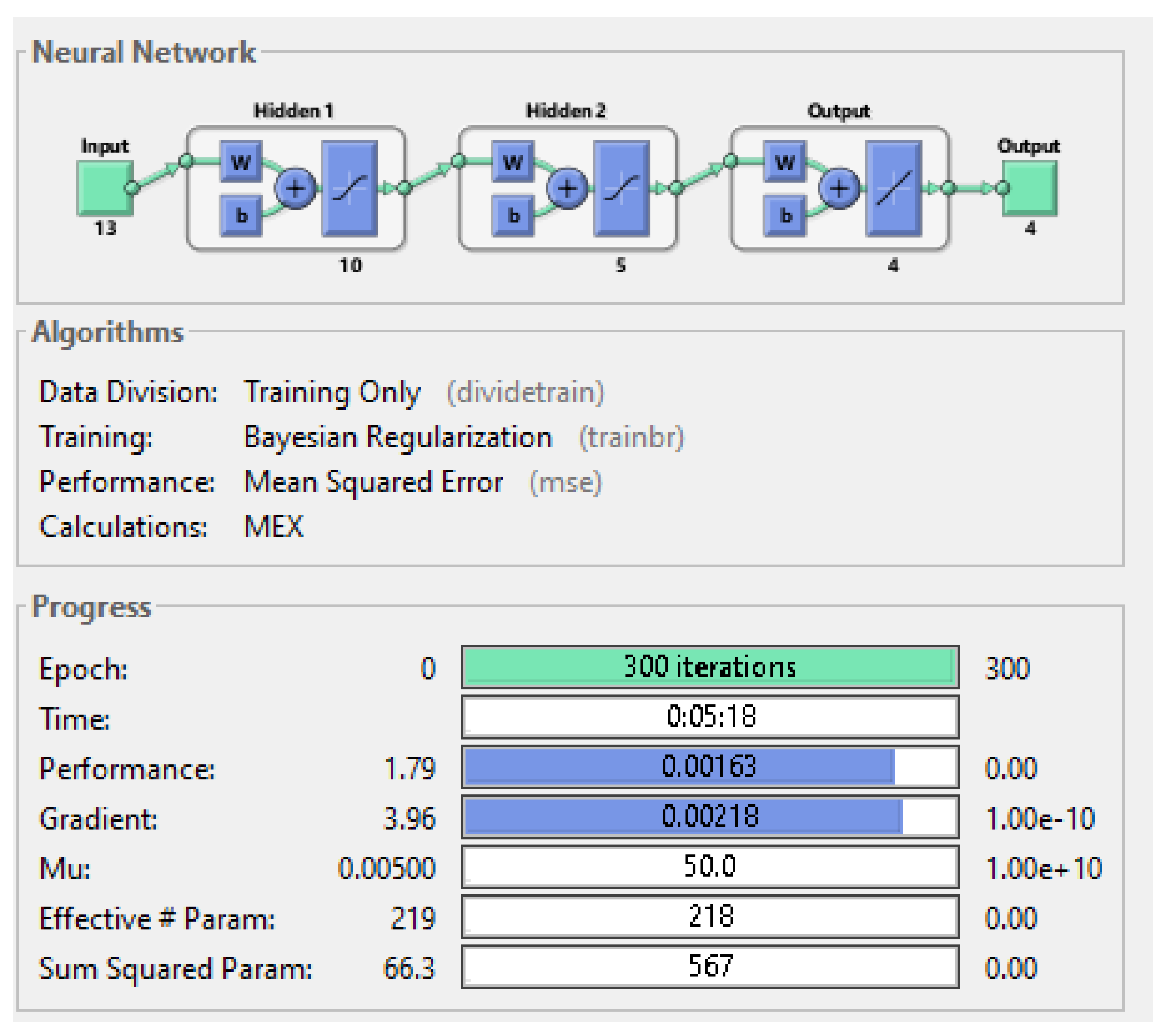
4.2. Step 2. Design ANN

The type of ANN is a very important issue for accurate estimation of the flux and speed. In this paper, each ANN has been designed as a FFNN. The Matlab toolbox has been used for this purpose. One can apply another NN type. The training function has been selected as Levenberg-Marquardt (trainlm). One can note that other training functions may be used. The objective function has been chosen as mean squared error (MSE). One can tune how many hidden layers can be used to accurately estimate the rotor speed. In the paper, the hidden layers are 2, with 10 and 5 neurons for the first and second layers, respectively.

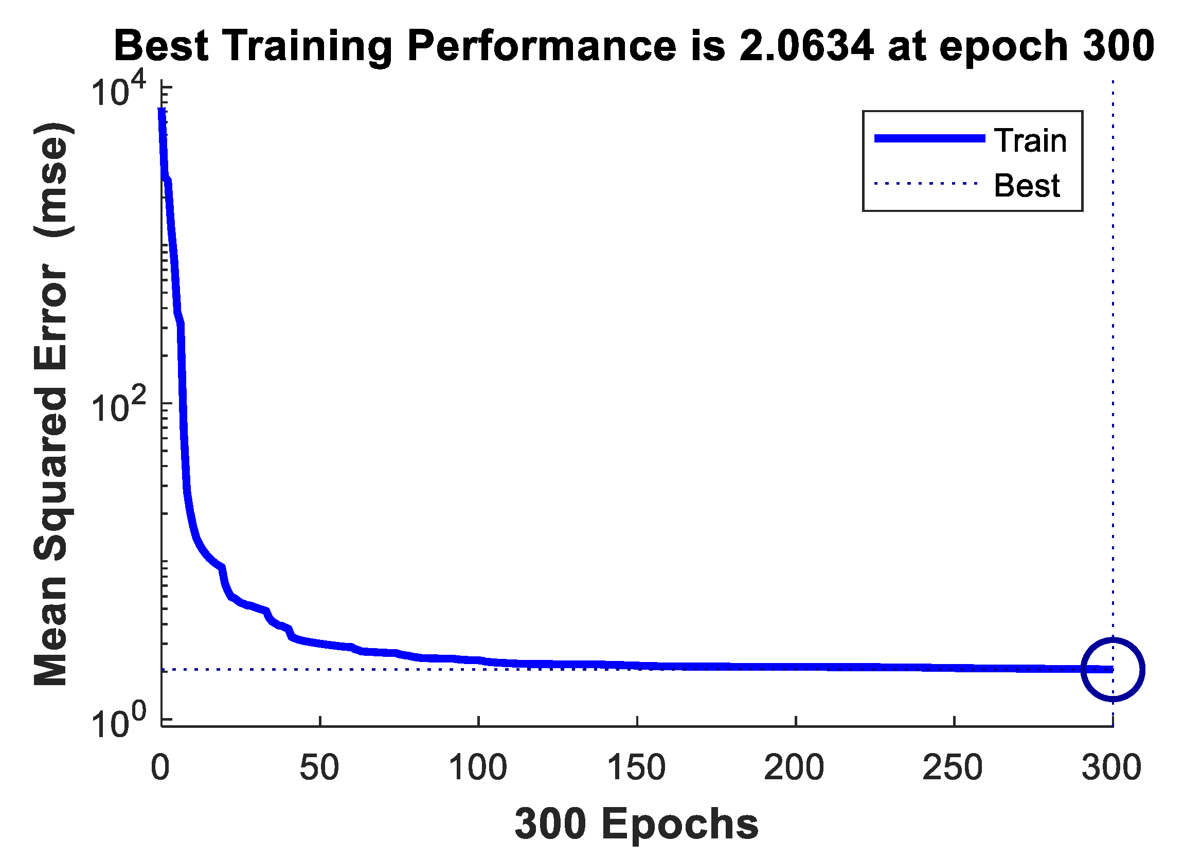
4.3. Step 3. Training ANNs

The training of each ANN has been done offline to save the implementation time. The training step has been done by extracting the actual states for speed and flux estimation. Firstly, the ANN-based speed estimation has been trained. The next step, the ANN-based flux estimation, has been trained because it needs the speed as one input data vector. The complete data set has been used for training the ANN.

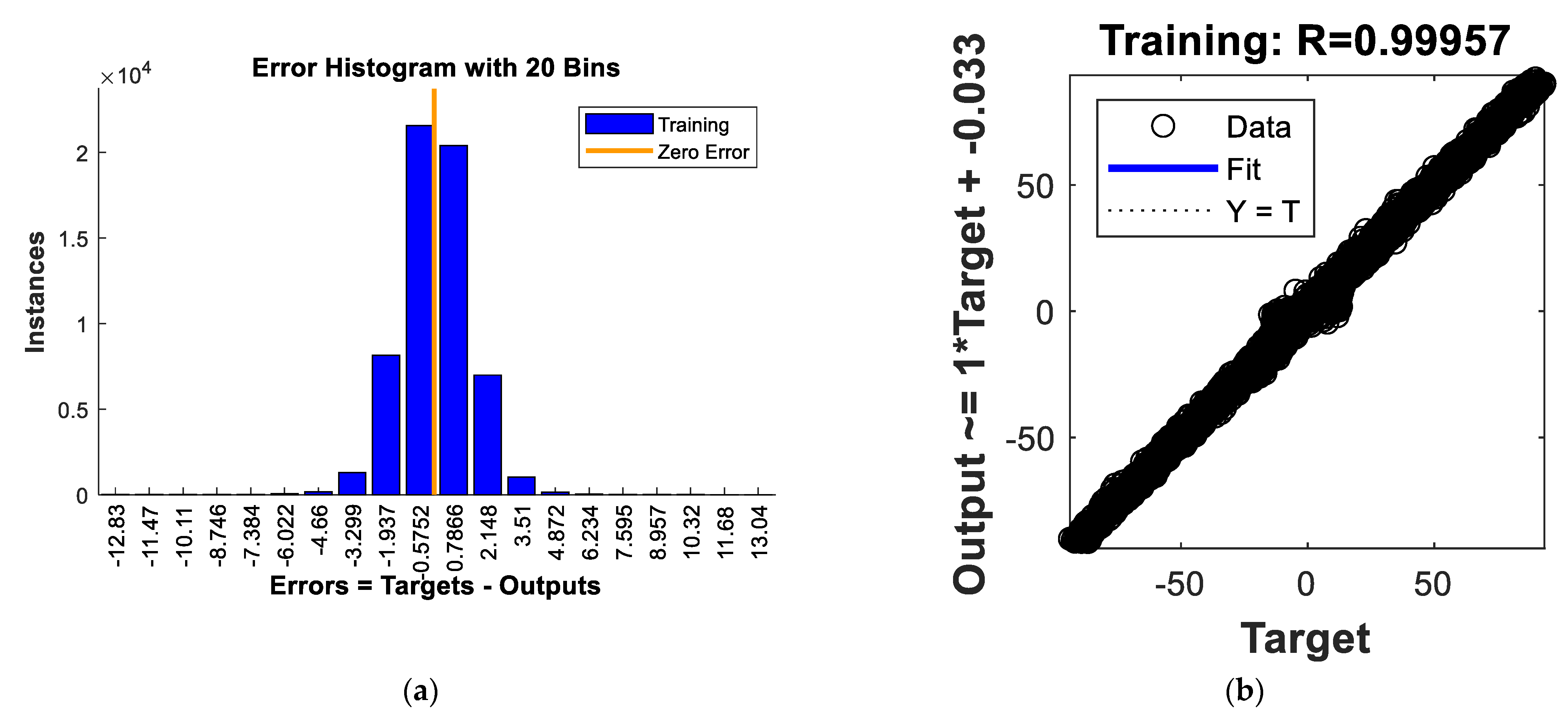
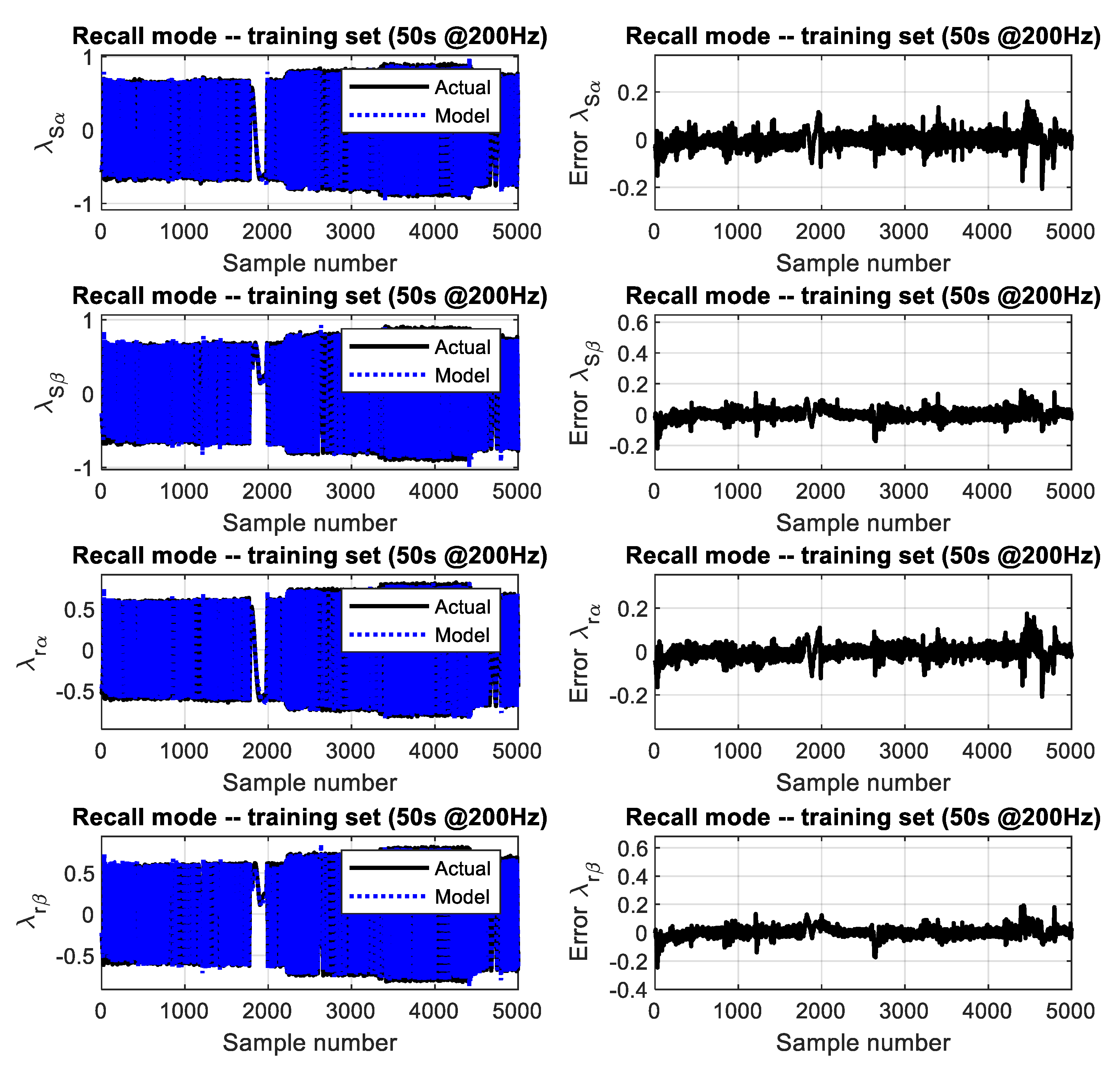
4.4. Step 4. Validation of the ANNs

We should test and validate the ANNs to show their performance and accuracy in this step. The testing should occur with consideration of the value of MSE, Regression. Moreover, testing the estimated values based on training and other testing data should occur. If the accuracy of ANN is not satisfied, the repeating of steps 2, 3, and 4 should be done.

4.5. Step 5. Exporting the Simulink Block for the Two ANNs

After releasing the effectiveness and accuracy of the ANN, exporting the ANN as a Simulink block should be done using the neural network (NN) Matlab Toolbox.
The steps for achieving an accurate estimation of the flux and rotor speed can be implemented as Listing 1 for the speed estimation, while the ANN flux estimator can be implemented in the same manner. This code show that the feed forward ANN has been selected. Moreover, two hidden layers have been used with 10 and 5 neurons, respectively.
Listing 1. ANN for speed estimator using NN Matlab toolbox.
  • Implemented simulink Model of the direct vector controlled IM drive.
  • Simulation simulink Model of the direct vector controlled IM drive.
  • Collecting input signals of training and save it as input_signals.
  • Collecting output signals of training and saving them as output_signals.
  • Design NN as (net_speed = feedforwardnet ([10 5]); net_speed.layers.transferFcn = ‘tansig’; net_speed.layers.transferFcn = ‘tansig’; net_speed.layers.transferFcn = ‘purelin’; net_speed.trainFcn = 'trainbr'; net_speed.divideFcn = ’dividetrain’;).
  • Configuration and traning of NN as (net_speed = configure (net_speed, input_signals, output_signals)).

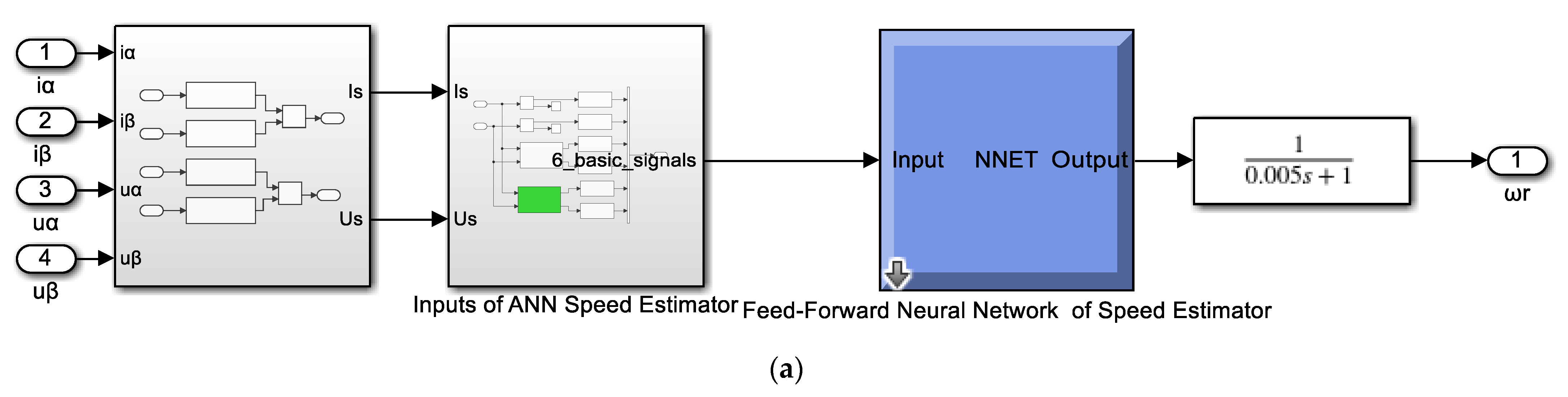
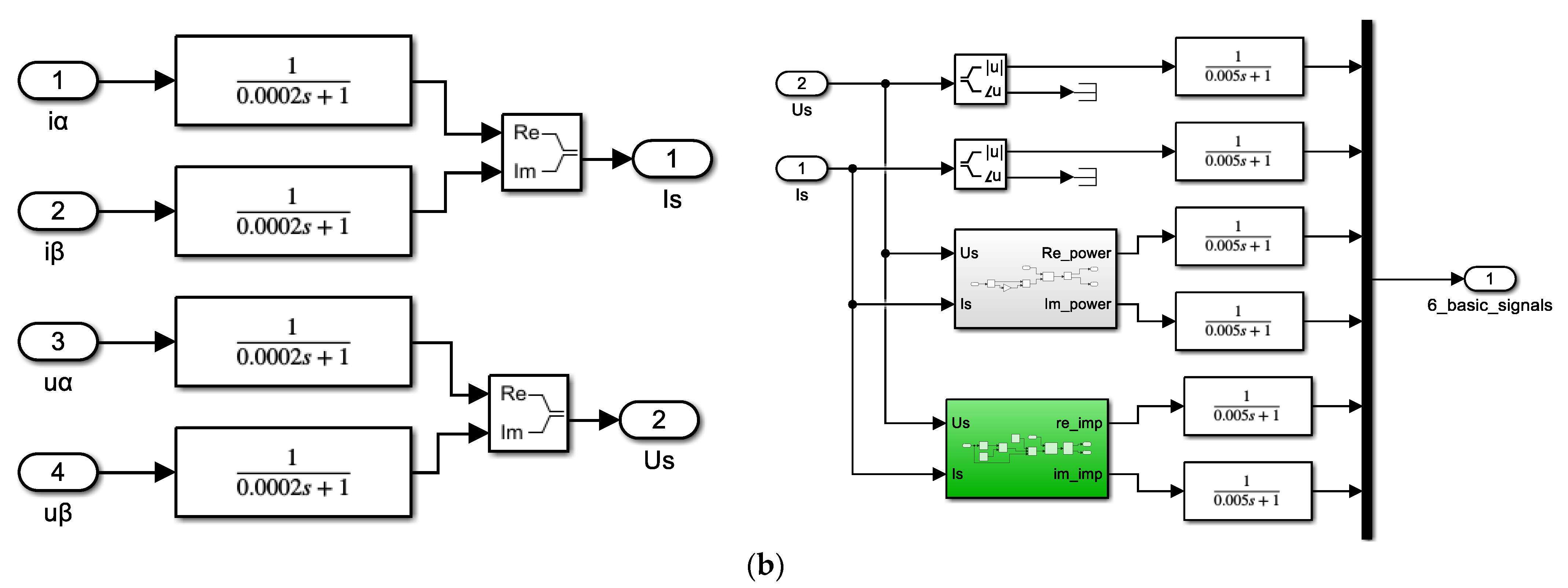
5. ANN Speed Estimator

The input and output data of the ANN speed estimator can be collected during the training by simulating the vector-controlled IM. The construction of the ANN block in Simulink is shown in Figure 4a. Figure 4b presents the implantation of each block in the ANN speed estimator. The ANN-based speed estimator is constructed as a linear time-invariant dynamic system consisting of a nonlinear neural function approximator through LPFs, as shown in Figure 4b.
The neural network toolbox of Matlab has been used to train, test, and validate the ANN speed estimator. Figure 5 shows implemented NN. The measured speed (which is used for training) and the estimated speed after training the ANN has been shown in Figure 6. The load torque of the motor, which has been applied for getting the training data, is also shown in Figure 6.
The performance of the ANN-based speed estimator considering MSE has been shown in Figure 7. Moreover, the error histogram and the regression between the estimated and actual data have been displayed in Figure 8. The figures show a linear regression between the predicted speed of the ANN-based speed estimator and the measured speed.

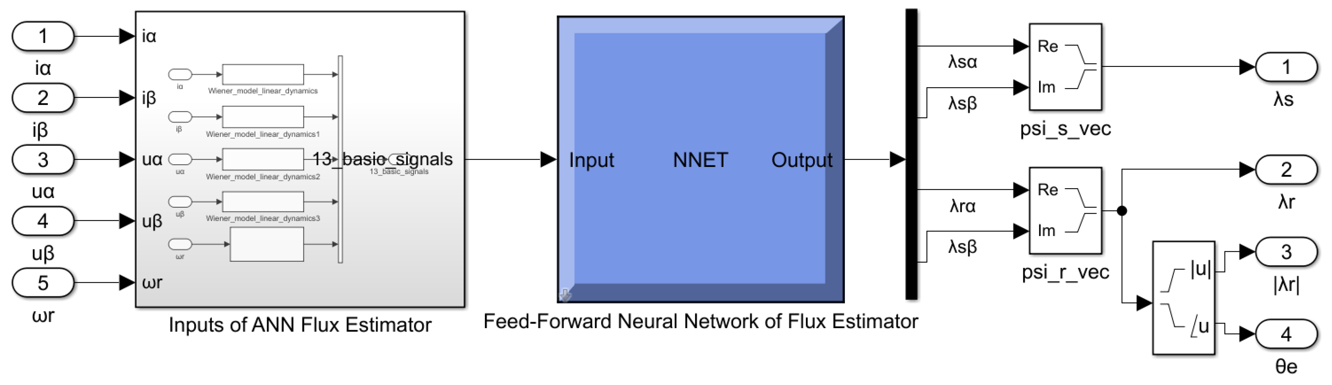
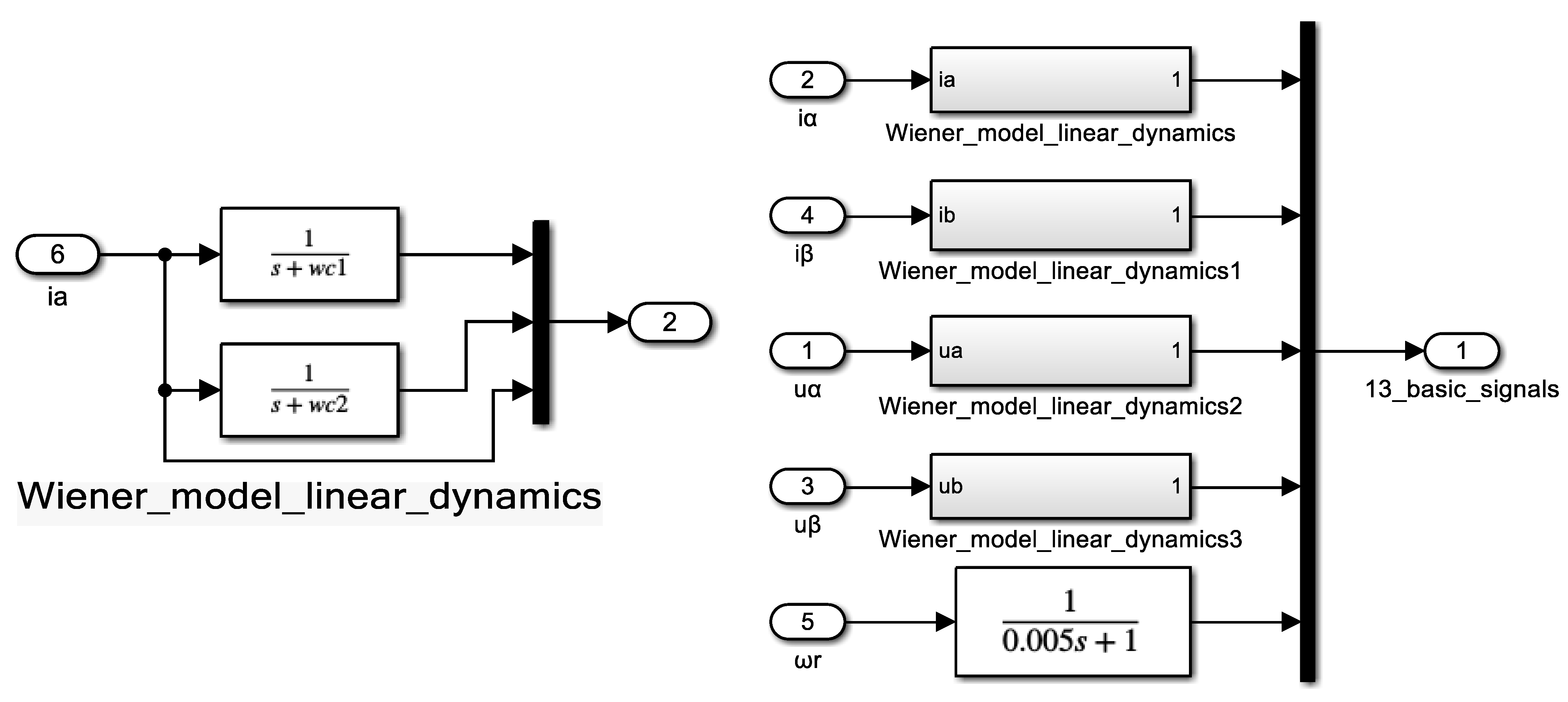
6. ANN Flux Estimator

The input data of the ANN flux estimator are based on the measured voltages and currents in α β and the rotor speed. The output is the stator and rotor fluxes.
The input and output data can be collected during the training by simulating the vector-controlled IM. The construction of the ANN block in Simulink can be shown in Figure 9. In Figure 10, the implantation of each block in the ANN flux estimator has been presented.
During the implementation of the ANN-based flux estimator, the exhaustive ANN-based flux estimator has been designed in such a linear time-invariant dynamic system. Moreover, the nonlinear neural function approximator has been interconnected among the inputs and the ANN, including the Wiener model. The inputs of the ANN-based flux estimator have been implemented through LPFs, as shown in Figure 10, with choosing the wc1 and wc2 to enhance the overall dynamic response and noise attenuation.
The neural network toolbox of Matlab has been used to train, test, and validate the ANN flux estimator. Figure 11 shows implemented ANN-based flux estimator. Figure 12 shows the input training data of the currents and voltages and the speed with adding zoomed captures. The measured fluxes (which are used for training) and the estimated fluxes after training the ANN are shown in Figure 13. The errors between the estimated and measured fluxes in α β for the rotor and stator are demonstrated in Figure 13. The figure shows the effectiveness and accuracy of the ANN-based flux estimator.

7. Results and Discussions

The Matlab package has been used in order to validate the complete control system associated with the ANNs for flux and speed estimation. Figure 14 shows the proposed sensorless vector-controlled induction motor drive-based ANNs for speed and flux estimators. The ANN-based flux and speed estimators have been shown in Figure 14b. Figure 14 has been presented and implemented in Simulink to reference researchers.

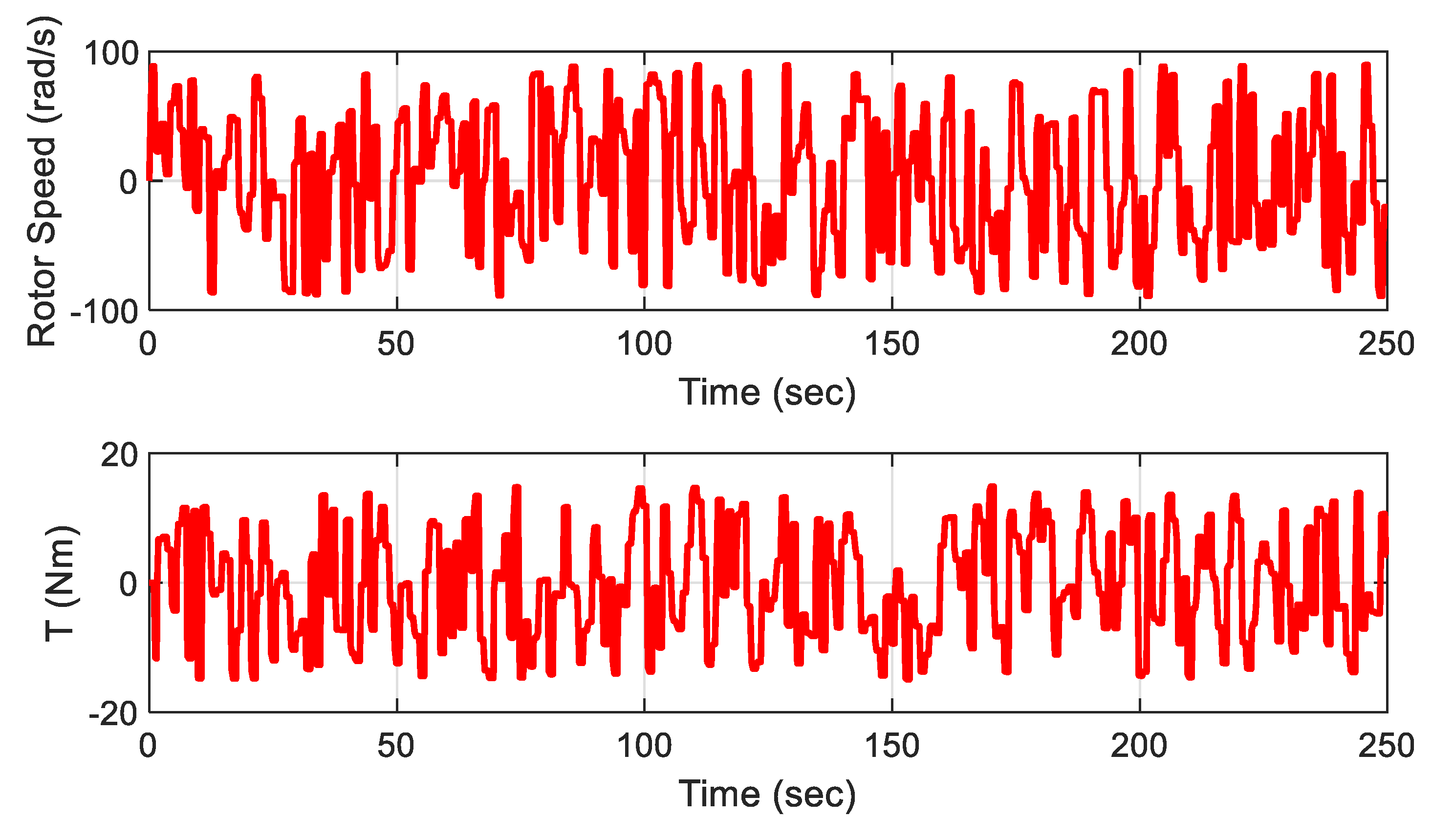
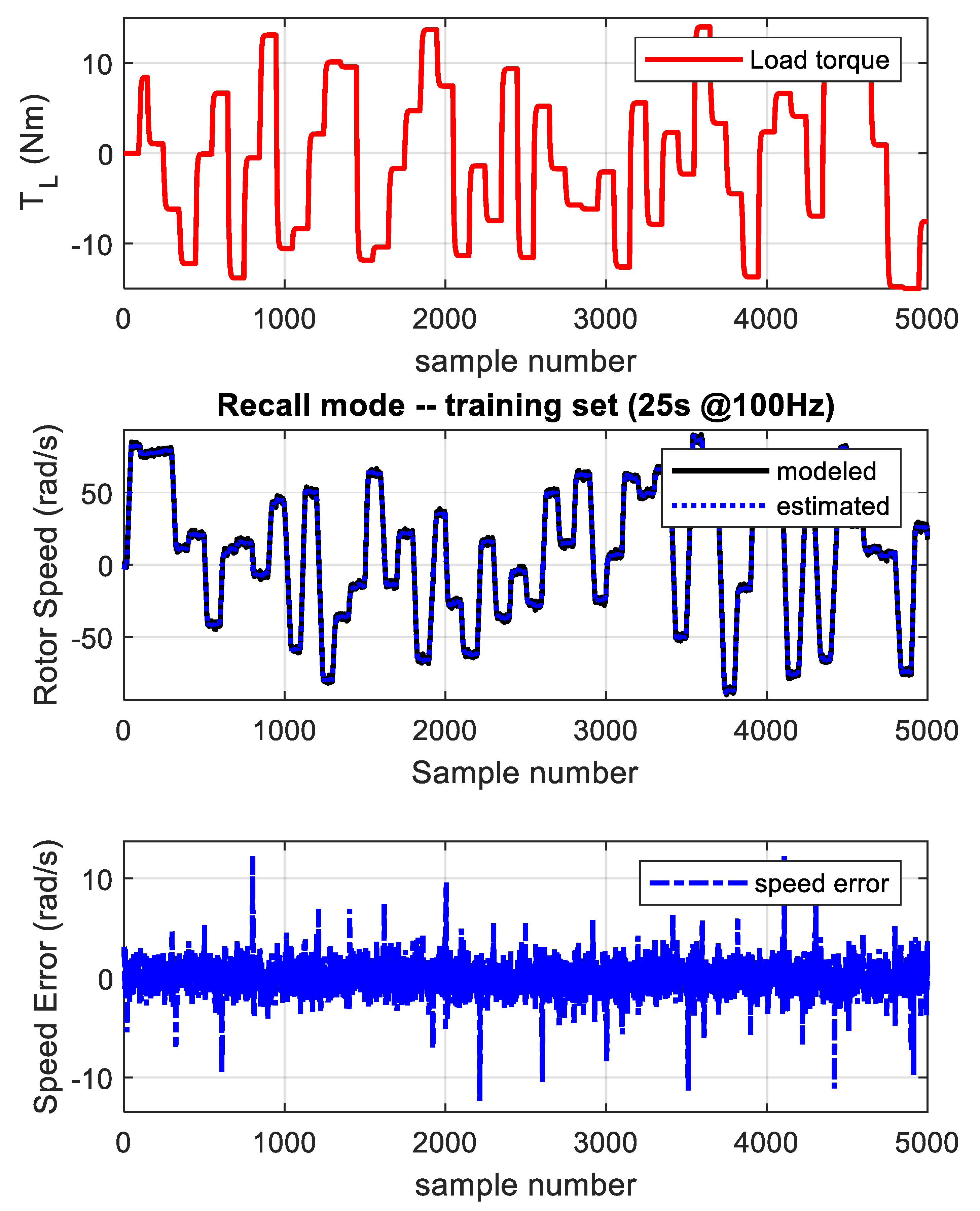
7.1. Case 1. Training Rotor Speed and Load Torque

The response of the ANN-based speed and flux estimators has been validated in this section considering 50 s from the training speed and load torque. The speed reference values are shown in Figure 15. Also, the load torque has been changed many times, as shown in Figure 16. The speed reference with the assumed load torque disturbance ensures testing the IM sensorless drive under many operation conditions. Figure 15 shows the study case’s reference actual and measured speeds. The reported actual and estimated speeds have the same track, which validates the accuracy of the ANN-based speed estimator. Figure 16 shows the load and electromagnetic torque under such a study case. For further validation of the ANN-based estimators, Figure 17 shows stator currents. Figure 18 shows the actual and estimated rotor fluxes. The zoomed capture of currents and fluxes has also been shown in Figure 17 and Figure 18. The results validate the control system’s effectiveness by using the offline ANN speed and flux estimators. Figure 19 demonstrates the successful implementation of vector control principles by visualizing α β rotor flux components. Figure 19a shows that the α β rotor flux components formed a circle plot between the estimated and measured rotor flux components. Moreover, Figure 19b shows that a good tracking of the estimated and actual rotor fluxes.

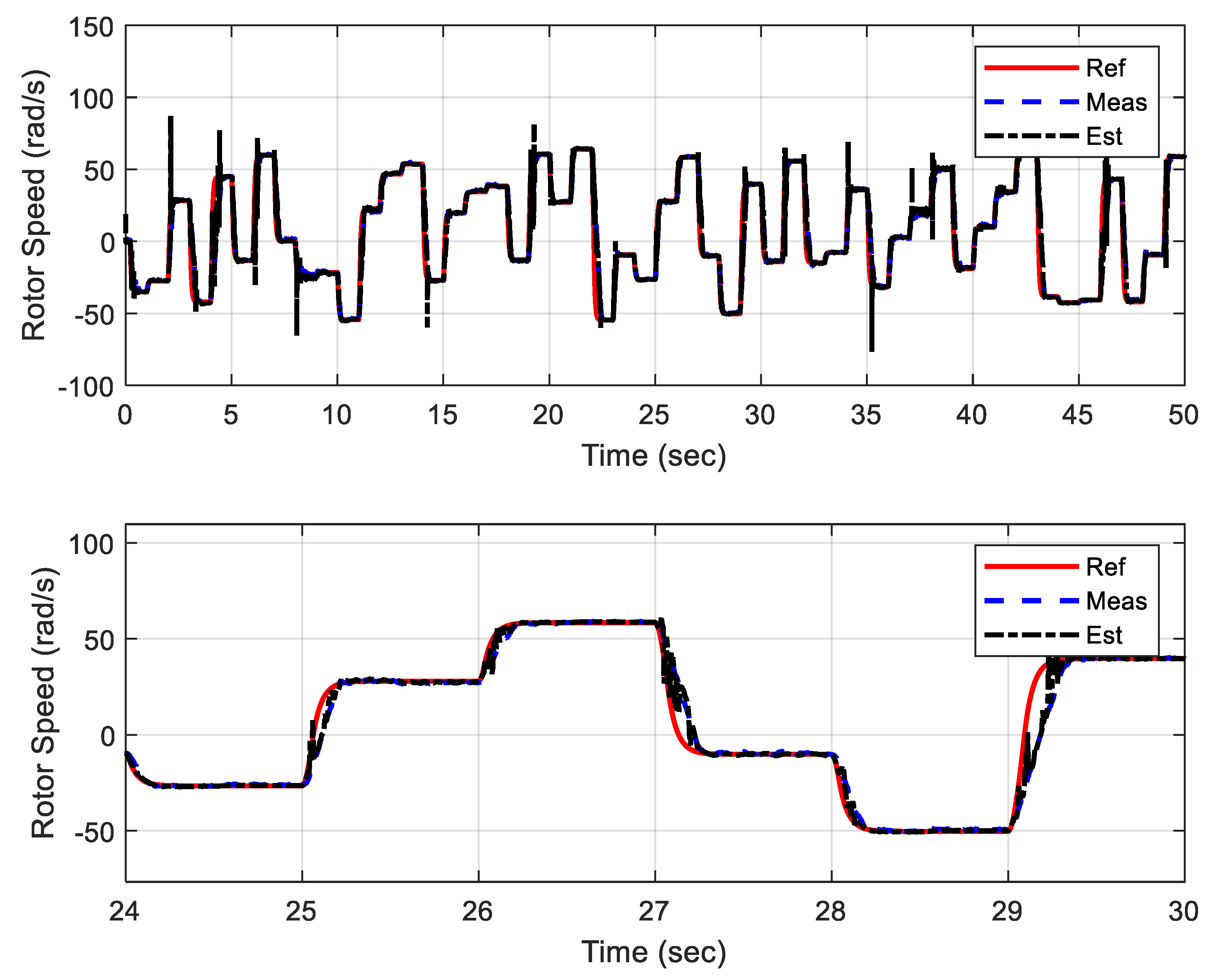
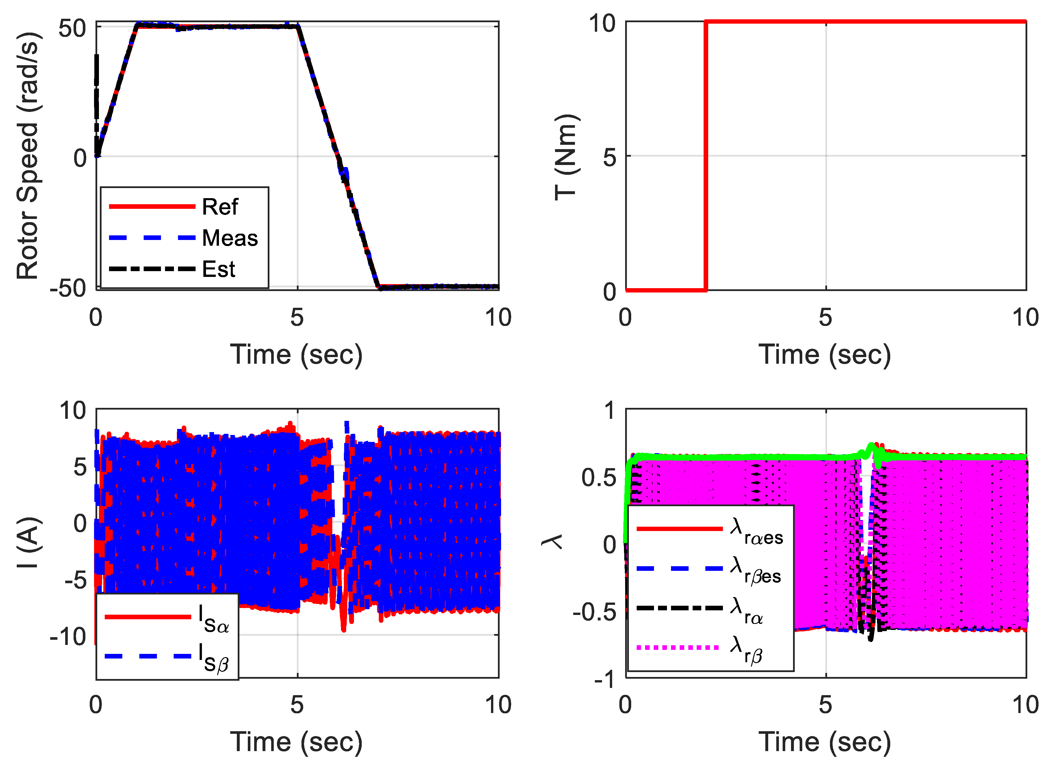
7.2. Case 2. Speed Reversal

In this case of study, the rotor speed and load torque have been assumed, as shown in Figure 20. This case is not included in the training data set. The speed has been increased from 0 to 50 rps, and the speed is constant in the interval from 1 s to 5 s, then the speed is reversed to 50 rps. The load torque has been stepped to 10 Nm at 2 s. The reference estimated and actual rotor speeds have been shown in Figure 20. The stator current and estimated and actual rotor flux are also shown in the figure. The results prove the effectiveness of the ANN-based speed and flux estimators over the simulation time.

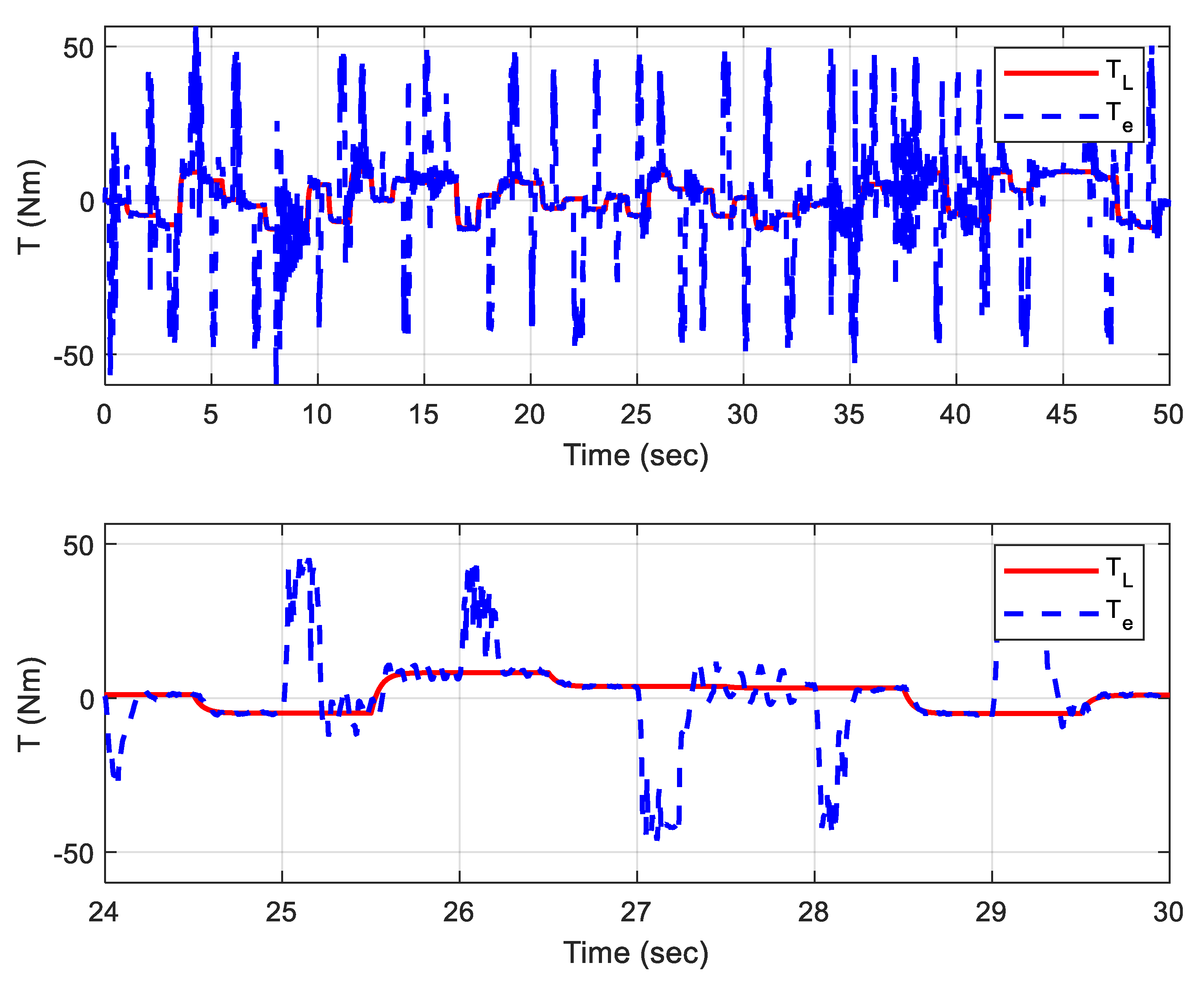
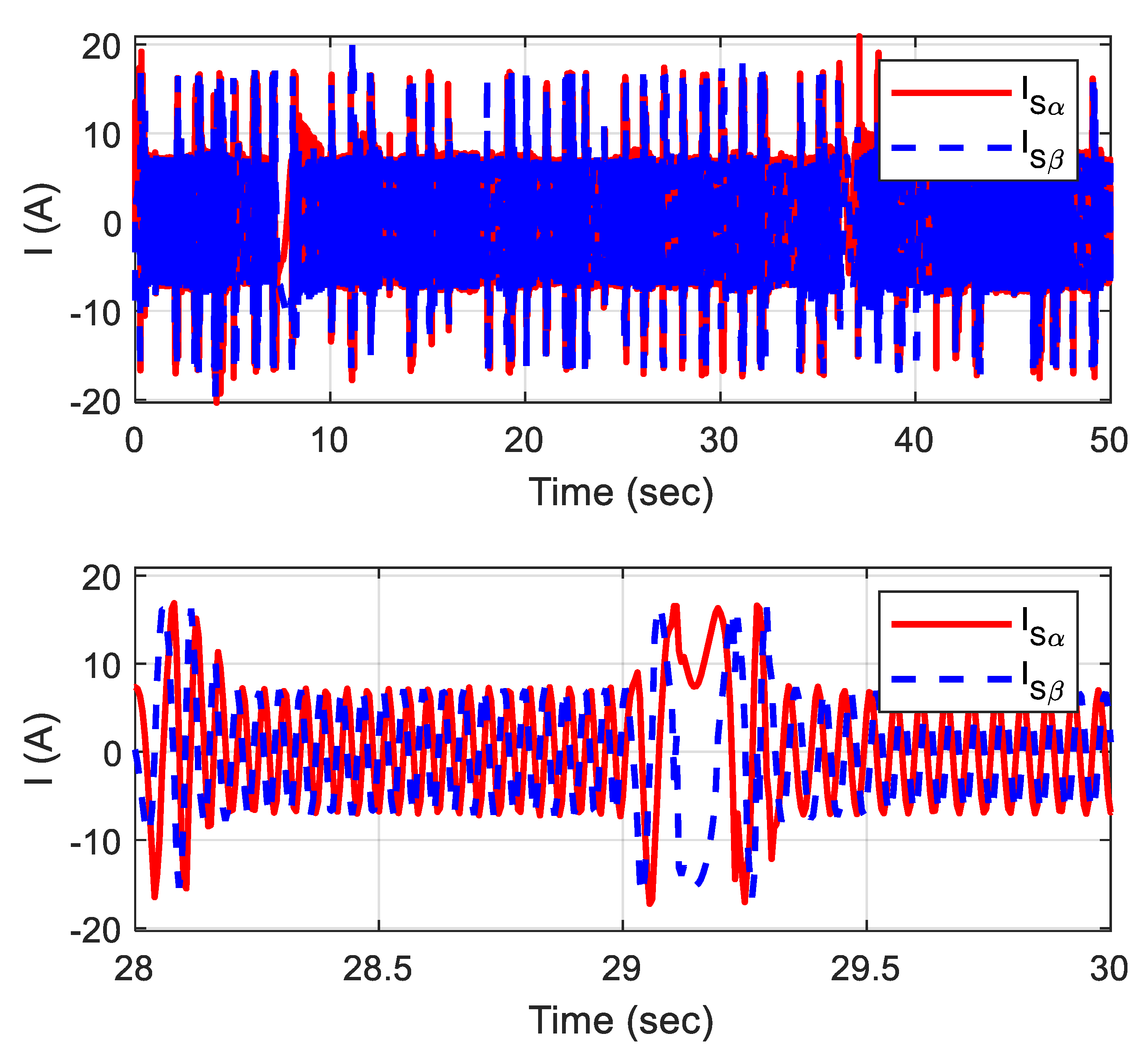
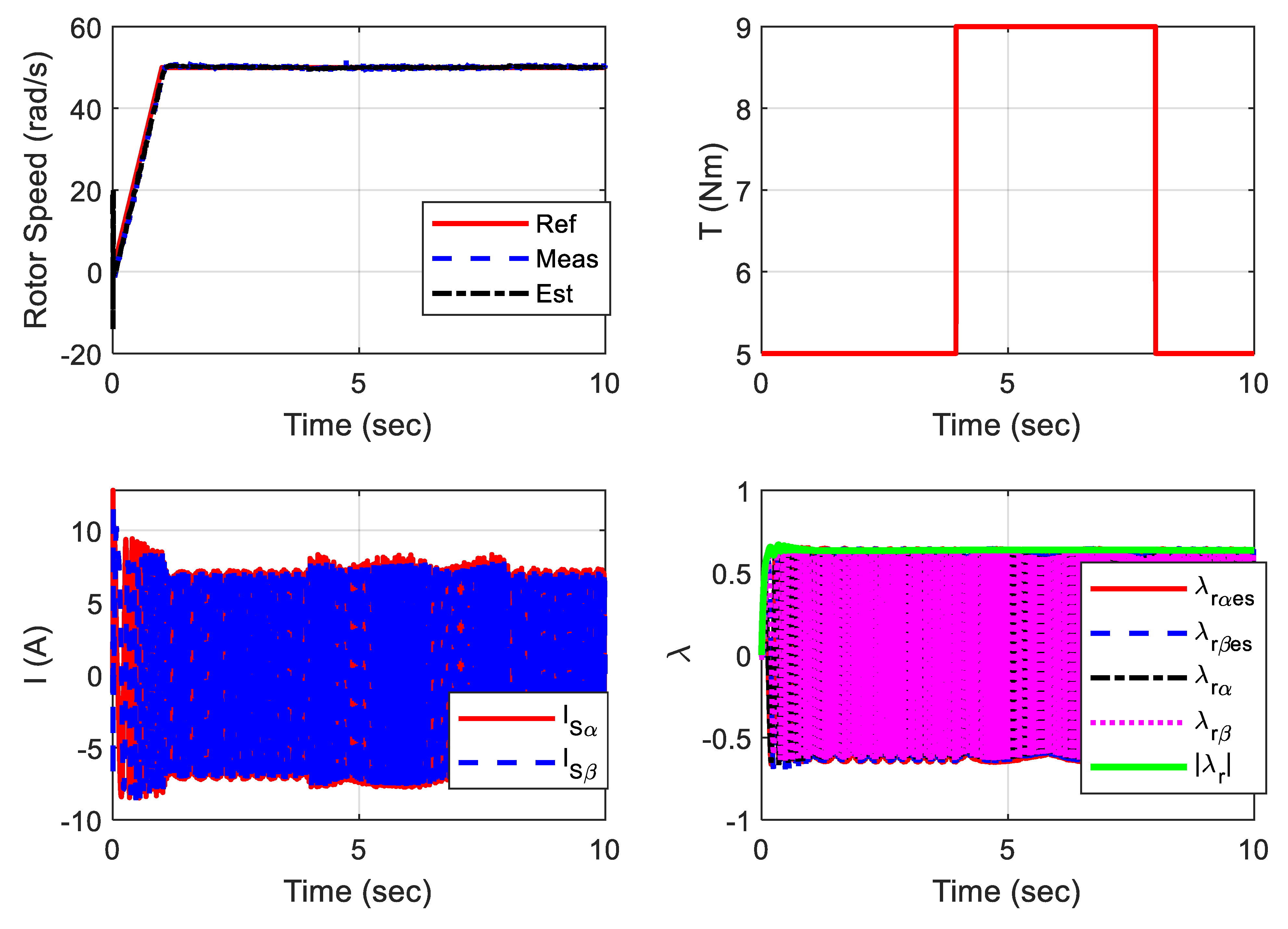
7.3. Case 3. Pulse Load Torque Disturbance

The studied case has been implemented to validate the ANN-based speed and flux estimators against load torque disturbance. The load is pulsed from 5 Nm to 9 Nm over 4 s to 8 s. Figure 21 shows the performance of the ANN-based estimators. The presented results validate the accuracy of the fluxes and rotor speed estimations.

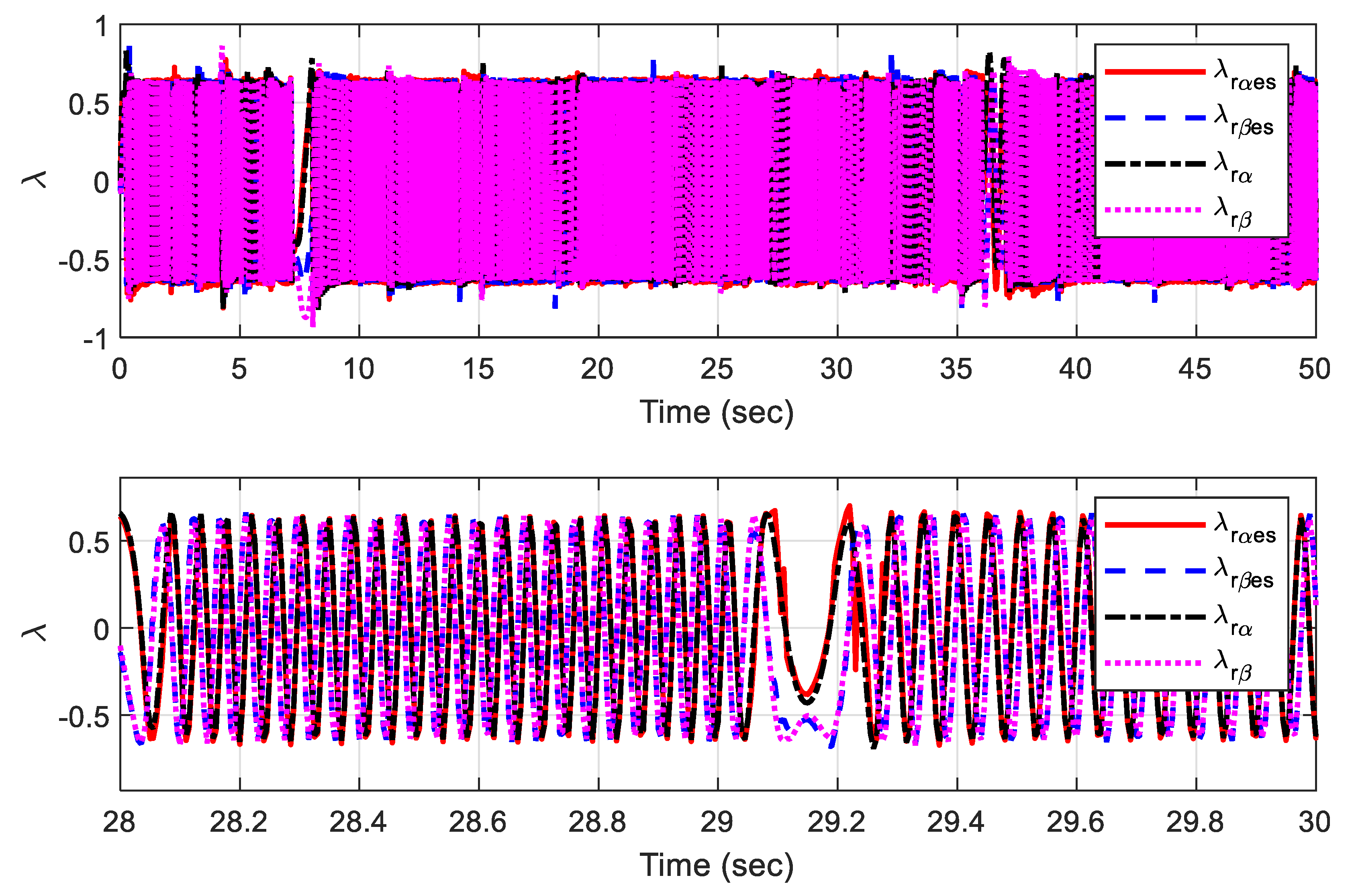
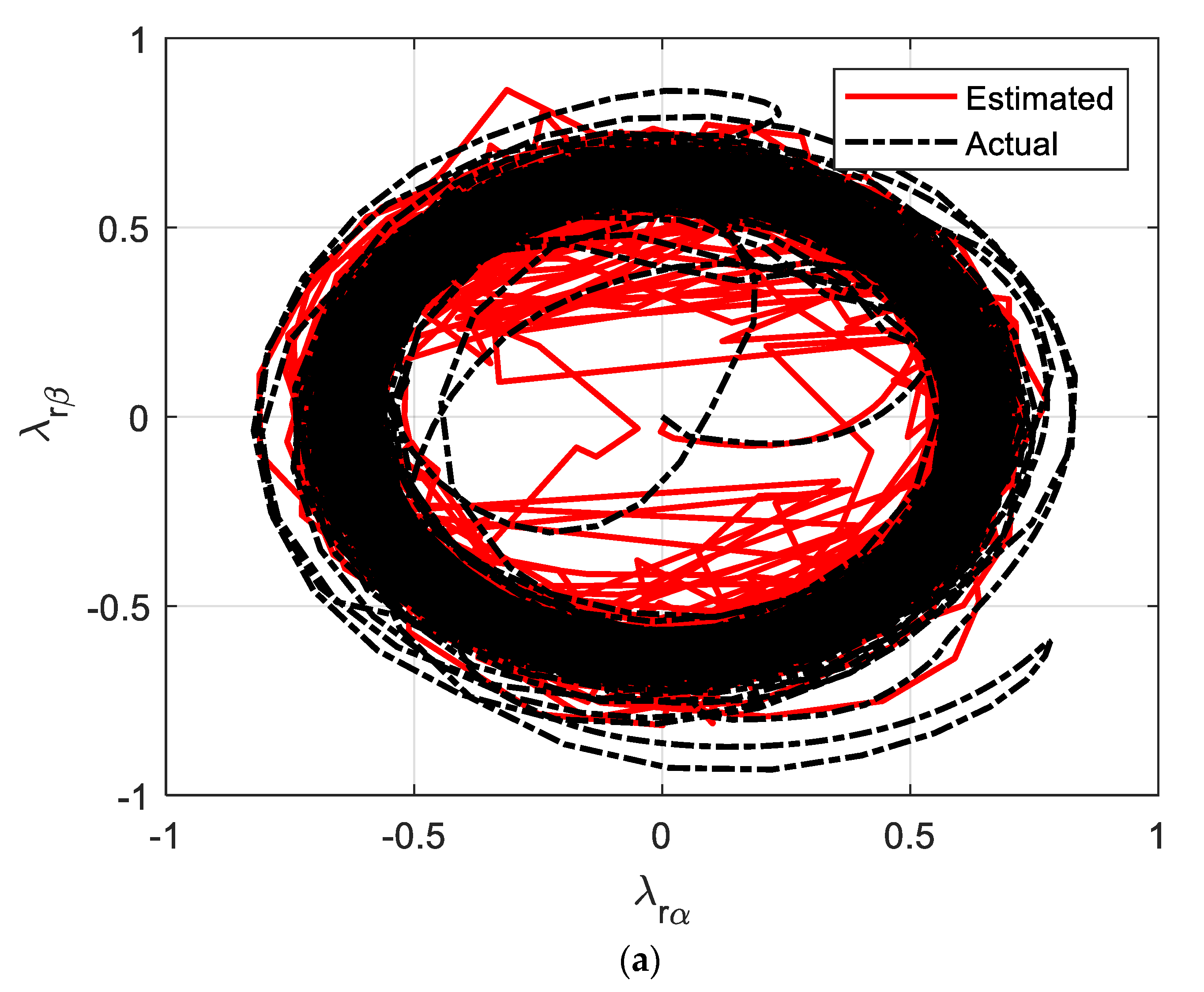
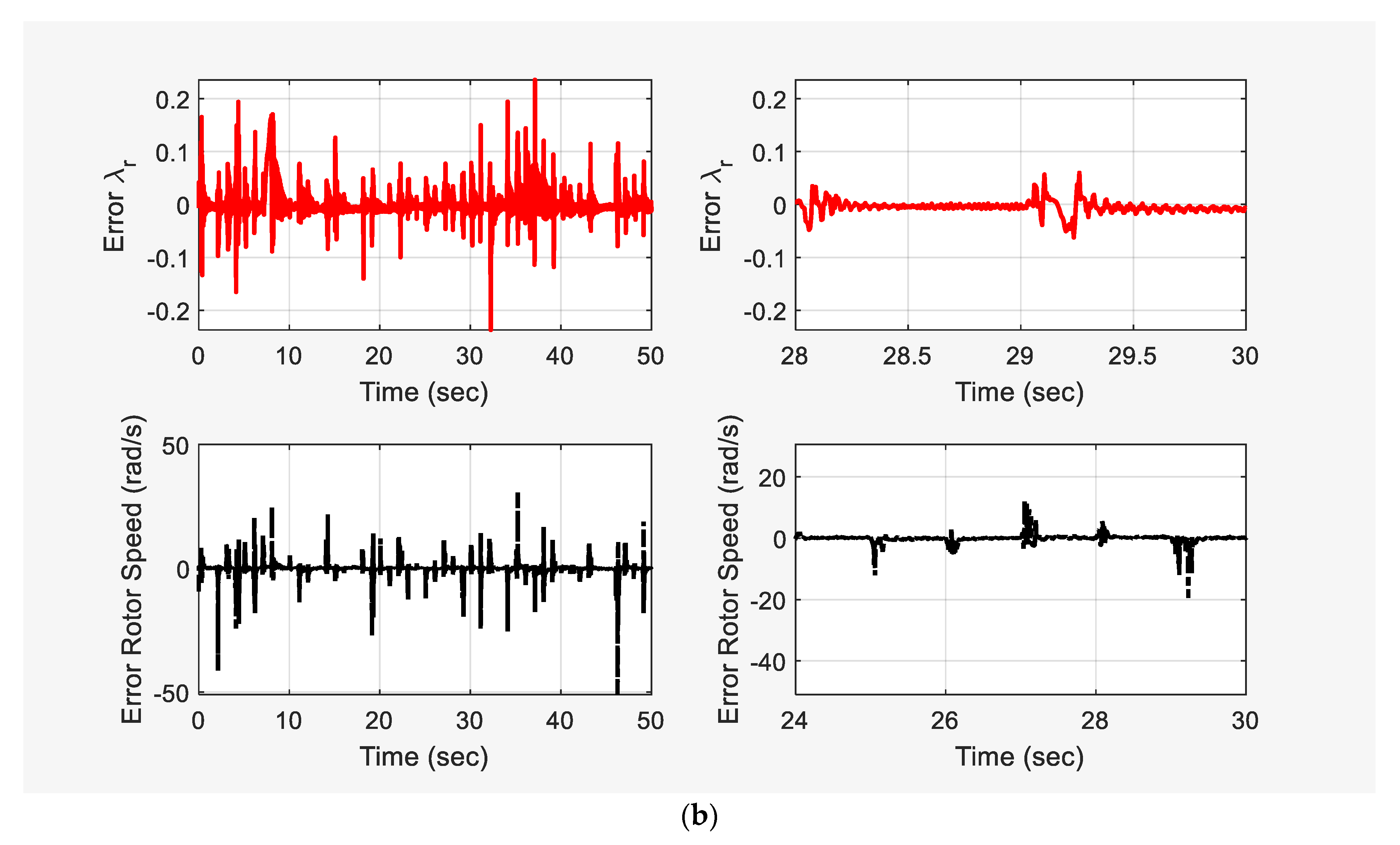
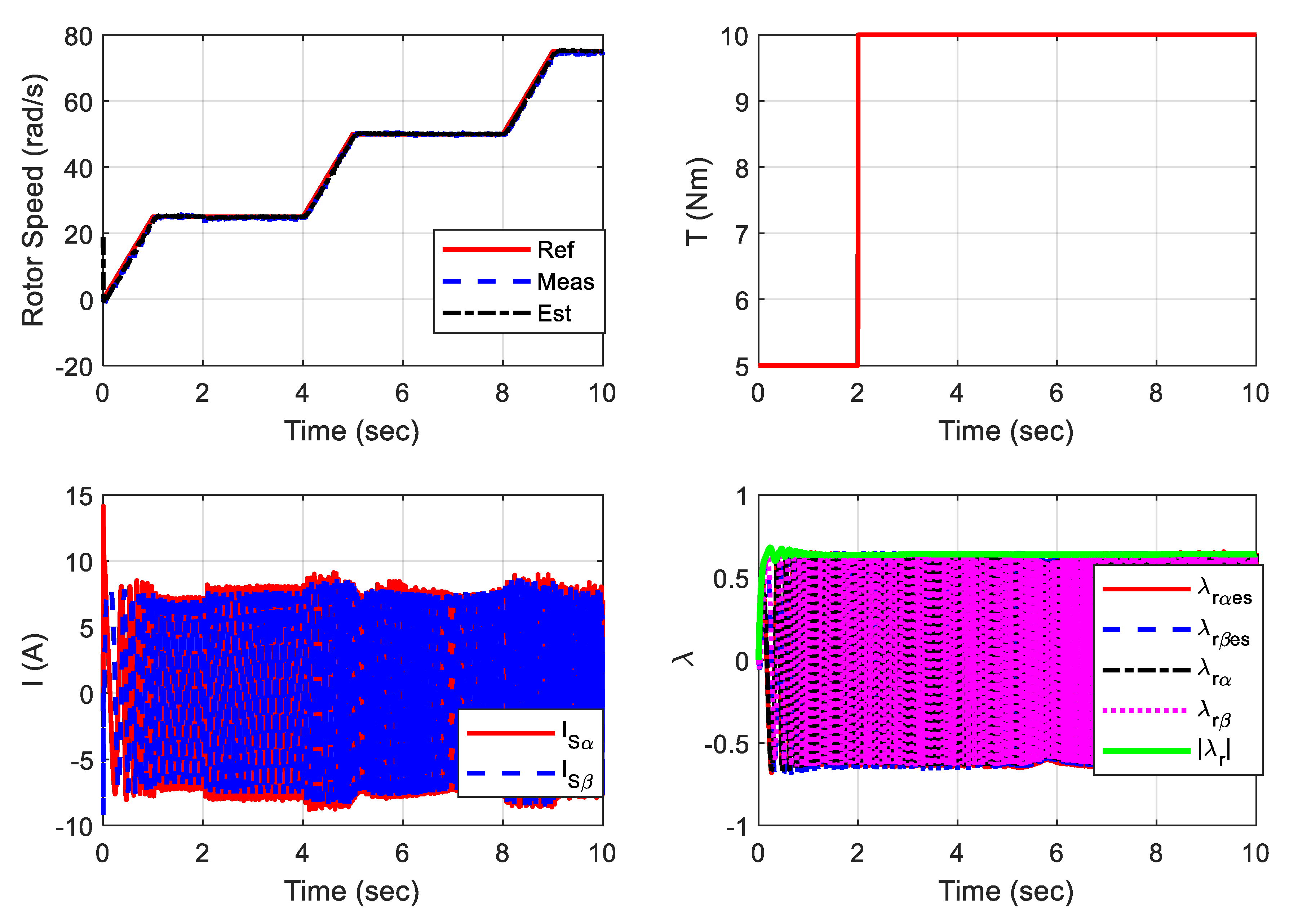
7.4. Case 4. Speed Variation

The studied case has been implemented to validate the ANN-based speed and flux estimators with a gradual rotor speed variation, as shown in Figure 22. Under this case of study, the load is kept constant during the first 2 s and stepped to the double at 2 s. Figure 22 shows the performance of the ANN-based estimators. The presented results validate the accuracy of the fluxes and rotor speed estimations. Moreover, the figure illustrates the good estimation of the estimated and actual rotor flux. Figure 23 validates the high dynamic performance of the vector-controlled IM drive with ANNs speed and flux estimation.

8. Conclusions and Future Directions

Two ANNs for estimating the speed and fluxes of IM drives have been realized and analyzed in this paper. The ANN estimators have been trained based on the data of the currents and voltages as well as the measured speed and fluxes offline to save the implementation time and cost. The validation of the ANN-based estimators has been achieved via MATLAB and Simulink. A successful representation of the training, testing, and validation of the ANN estimators has been presented as a reference for engineers and researchers. The simulation results demonstrate that the ANN-based speed and flux estimators accurately estimate the speed and fluxes. The estimated speed and fluxes have the same track as the actual ones via a wide speed range considering the load torque disturbance. Other advanced ANN estimators can be applied for various AC drives and industrial applications in future work. A limitation of this presented work, the selection of such basic ANN of FFNN is due to hyperparameter optimization with an approximate gradient method that may not be used with Recurrent Neural Network (RNN). In future work, RNNs should be considered and tested, which may lead to improving the effectiveness of the estimation process rather than FFNN. Moreover, real measurements with a speedometer, magnetic field sensor, current sensors, and voltage sensors should be used with the experimental setup up for more validation of ANN estimators.

Author Contributions

Conceptualization, A.A.Z.D. and K.A.D.; Data curation, A.A.Z.D.; Formal analysis, A.A.Z.D. and Z.M.A.; Investigation, A.A.Z.D. and S.A.; Methodology, A.A.Z.D. and M.A.E.; Project administration, A.A.Z.D. and K.A.D.; Resources, A.A.Z.D., M.A.E., K.A.D. and S.A.; Software, A.A.Z.D., K.A.D. and Z.M.A.; Supervision, K.A.D.; Validation, A.A.Z.D. and Z.M.A.; Visualization, M.A.E.; Writing—original draft, A.A.Z.D. and M.A.E.; Writing—review & editing, A.A.Z.D., K.A.D., S.A. and Z.M.A. All authors have read and agreed to the published version of the manuscript.

Funding

This research received no external funding.

Institutional Review Board Statement

Not Applicable.

Informed Consent Statement

Not Applicable.

Data Availability Statement

Not Applicable.

Acknowledgments

The current research work is not funded by any organization/foundation.

Conflicts of Interest

The authors declare no conflict of interest. Non-financial competing interest.

Appendix A

Table A1. Parameters and data specifications of the induction motor.
Rated power (kW)1.5Rated voltage (V)127/220
Rated current (A)12/6.9Rated frequency (Hz)60
Rs (Ω)1.54Rr (Ω)1.294
Ls (mH)100.4Lr (mH)96.9
Lm (mH)91.5Rated rotor flux, (wb)0.6
Jm (kg·m2)0.15Rated speed (rpm)930
P3

References

  1. Mehrotra, P.; Quaicoe, J.E.; Venkatesan, R. Development of an artificial neural network based induction motor speed estimator. In Proceedings of the PESC Record 27th Annual IEEE Power Electronics Specialists Conference, Baveno, Italy, 23–27 June 1996. [Google Scholar] [CrossRef]
  2. Hu, J.; Wu, B. New integration algorithms for estimating motor flux over a wide speed range. IEEE Trans. Power Electron. 1998, 13, 969–977. [Google Scholar] [CrossRef]
  3. Karanayil, B.; Rahman, M.F.; Grantham, C. Online Stator and Rotor Resistance Estimation Scheme Using Artificial Neural Networks for Vector Controlled Speed Sensorless Induction Motor Drive. IEEE Trans. Ind. Electron. 2007, 54, 167–176. [Google Scholar] [CrossRef]
  4. Diab, A.A.Z.; Al-Sayed, A.-H.M.; Mohammed, H.H.A.; Mohammed, Y.S. Literature Review of Induction Motor Drives. In SpringerBriefs in Electrical and Computer Engineering; Springer: Singapore, 2020; pp. 7–18. [Google Scholar]
  5. Tiwari, A.; Kumar, B.; Chauhan, Y.K. ANN based RF-MRAS speed estimation of induction motor drive at low speed. In Proceedings of the 2017 International conference of Electronics, Communication and Aerospace Technology (ICECA), Coimbatore, India, 20–22 April 2017. [Google Scholar] [CrossRef]
  6. Diab, A.A.Z.; Pankratov, V.V. Model predictive control of vector controlled induction motor drive. In Proceedings of the 2012 7th International Forum on Strategic Technology (IFOST), Tomsk, Russia, 18–21 September 2012. [Google Scholar] [CrossRef]
  7. Aziz, A.; Rez, H.; Diab, A. Robust Sensorless Model-Predictive Torque Flux Control for High-Performance Induction Motor Drives. Mathematics 2021, 9, 403. [Google Scholar] [CrossRef]
  8. Varga, T.; Benšić, T.; Štil, V.J.; Barukčić, M. Continuous Control Set Predictive Current Control for Induction Machine. Appl. Sci. 2021, 11, 6230. [Google Scholar] [CrossRef]
  9. Wlas, M.; Krzeminski, Z.; Toliyat, H.A.; Krzemiriski, Z. Neural-Network-Based Parameter Estimations of Induction Motors. IEEE Trans. Ind. Electron. 2008, 55, 1783–1794. [Google Scholar] [CrossRef]
  10. Blaschke, F. The principle of field orientation as applied to the new transvector closed loop system for rotating field machines. Siemens Rev. 1972, 39, 217–220. [Google Scholar]
  11. Grzesiak, L.M.; Ufnalski, B. DTC drive with ANN-based stator flux estimator. In Proceedings of the 2005 European Conference on Power Electronics and Applications, Dresden, Germany, 11–14 September 2005. [Google Scholar] [CrossRef]
  12. Çetin, O.; Dalcalı, A.; Temurtas, F. A comparative study on parameters estimation of squirrel cage induction motors using neural networks with unmemorized training. Eng. Sci. Technol. Int. J. 2020, 23, 1126–1133. [Google Scholar] [CrossRef]
  13. Pal, A.; Das, S. Development of energy efficient scheme for speed sensorless induction motor drive. Int. Trans. Electr. Energy Syst. 2020, 30, e12448. [Google Scholar] [CrossRef]
  14. Mehrotra, P.; Quaicoe, J.E.; Venkatesan, R. Speed estimation of induction motor using artificial neural networks. In Proceedings of the 1996 IEEE IECON. 22nd International Conference on Industrial Electronics, Control, and Instrumentation, Taipei, Taiwan, 9 August 1996. [Google Scholar] [CrossRef]
  15. Chitra, A.; Himavathi, S. A modified neural learning algorithm for online rotor resistance estimation in vector controlled induction motor drives. Front. Energy 2015, 9, 22–30. [Google Scholar] [CrossRef]
  16. Chen, J.; Huang, J.; Sun, Y. Resistances and Speed Estimation in Sensorless Induction Motor Drives Using a Model With Known Regressors. IEEE Trans. Ind. Electron. 2018, 66, 2659–2667. [Google Scholar] [CrossRef]
  17. Devanshu, A.; Singh, M.; Kumar, N. Nonlinear flux observer-based feedback linearisation control of IM drives with ANN speed and flux controller. Int. J. Electron. 2020, 108, 139–161. [Google Scholar] [CrossRef]
  18. Grzesiak, L.M.; Ufnalski, B. Neural stator flux estimator with dynamical signal preprocessing. In Proceedings of the 2004 IEEE Africon. 7th Africon Conference in Africa (IEEE Cat. No.04CH37590), Gaborone, Botswana, 15–17 September 2004. [Google Scholar] [CrossRef]
  19. Bensalem, Y.; Abdelkrim, M.N. A sensorless neural model reference adaptive control for induction motor drives. In Proceedings of the 3rd International Conference on Signals, Circuits and Systems (SCS), Medenine, Tunisia, 6–8 November 2009. [Google Scholar] [CrossRef]
  20. Chitra, A.; Himavathi, S. Investigation and analysis of high performance green energy induction motor drive with intelligent estimator. Renew. Energy 2016, 87, 965–976. [Google Scholar] [CrossRef]
  21. Grzesiak, L.M.; Meganck, V.; Sobolewski, J.; Ufnalski, B. Genetic Algorithm for Parameters Optimization of ANN-based Speed Controller. In Proceedings of the EUROCON 2007—The International Conference on “Computer as a Tool”, Warsaw, Poland, 9–12 September 2007. [Google Scholar] [CrossRef]
  22. Kowol, P.; Szczygieł, M.; Sciuto, G.L.; Capizzi, G. Modeling of Magnetorheological Fluids Relative Magnetic Permeability by using a Neural Network approach. In Proceedings of the 2020 IEEE 20th Mediterranean Electrotechnical Conference (MELECON), Palermo, Italy, 16–18 June 2020; pp. 25–28. [Google Scholar]
Figure 1. Block diagram of DFOC for IM drive.
Mathematics 10 01348 g001
Figure 2. Applied reference speed and load torque while collecting the training data.
Mathematics 10 01348 g002
Figure 3. Imposed noise for rotor and stator fluxes, stator currents, rotor speed, and stator resistance.
Mathematics 10 01348 g003
Figure 4. (a) Feed-forward neural network of speed estimator; (b) detailed implementation of ANN speed estimator.
Mathematics 10 01348 g004aMathematics 10 01348 g004b
Figure 5. Simulink diagram ANN-based speed estimator.
Mathematics 10 01348 g005
Figure 6. Network performance considering the measured speed and estimated speed.
Mathematics 10 01348 g006
Figure 7. Performance of the ANN-based speed estimator considering mean squared error (MSE).
Mathematics 10 01348 g007
Figure 8. Performance of the ANN-based speed estimator; (a) error histogram and (b) regression.
Mathematics 10 01348 g008
Figure 9. The feed-forward neural network of flux estimator.
Mathematics 10 01348 g009
Figure 10. Detailed implementation of ANN flux estimator.
Mathematics 10 01348 g010
Figure 11. Simulink diagram ANN-based flux estimator.
Mathematics 10 01348 g011
Figure 12. Input training data of the currents and voltages and the speed with adding zoomed captures.
Mathematics 10 01348 g012
Figure 13. Network performance considering the measured stator and rotor fluxes and estimated ones.
Mathematics 10 01348 g013
Figure 14. (a) The Simulink model of speed sensorless induction motor drives with ANN-based speed and flux estimators; (b) the Simulink model of the two ANN-based speed and flux estimators.
Mathematics 10 01348 g014
Figure 15. Dynamic performance of reference measured and estimated speeds.
Mathematics 10 01348 g015
Figure 16. Dynamic performance of load and electromagnetic torques.
Mathematics 10 01348 g016
Figure 17. Dynamic performance of stator currents.
Mathematics 10 01348 g017
Figure 18. Dynamic performance of actual and estimated fluxes.
Mathematics 10 01348 g018
Figure 19. (a) Actual and estimated α-β rotor flux components and (b) the error between the measured and estimated values of rotor speed and rotor flux.
Mathematics 10 01348 g019aMathematics 10 01348 g019b
Figure 20. Response of the proposed drive with ANN-based estimators considering reversal speed.
Mathematics 10 01348 g020
Figure 21. Response of the proposed drive with ANN-based estimators considering the case of pulse load torque disturbance.
Mathematics 10 01348 g021
Figure 22. Response of the proposed drive with ANN-based estimators considering the case of rotor speed variation.
Mathematics 10 01348 g022
Figure 23. Actual and estimated α − β rotor flux components considering the case of rotor speed variation.
Mathematics 10 01348 g023
Publisher’s Note: MDPI stays neutral with regard to jurisdictional claims in published maps and institutional affiliations.

