Article

Nonlinear Static Stability of Imperfect Bio-Inspired Helicoidal Composite Beams

by
Nazira Mohamed
1,
Salwa A. Mohamed
1 and
Mohamed A. Eltaher
2,3,*
1
Department of Engineering Mathematics, Faculty of Engineering, Zagazig University, Zagazig P.O. Box 44519, Egypt
2
Mechanical Engineering Department, Faculty of Engineering, King Abdulaziz University, Jeddah P.O. Box 80204, Saudi Arabia
3
Mechanical Design and Production Department, Faculty of Engineering, Zagazig University, Zagazig P.O. Box 44519, Egypt
*
Author to whom correspondence should be addressed.
Mathematics 2022, 10(7), 1084; https://doi.org/10.3390/math10071084
Submission received: 6 March 2022 / Revised: 24 March 2022 / Accepted: 24 March 2022 / Published: 28 March 2022
(This article belongs to the Section Engineering Mathematics)

Abstract

:
The objective of this manuscript is to develop, for the first time, a mathematical model for the prediction of buckling, postbuckling, and nonlinear bending of imperfect bio-inspired helicoidal composite beams with nonlinear rotation angle. The equilibrium nonlinear integrodifferential equations of imperfect (curved) helicoidal composite beams are derived from the Euler–Bernoulli kinematic assumption. The differential integral quadrature method (DIQM) and Newton-iterative method are employed to evaluate the response of imperfect helicoidal composite beams. Following the validation of the proposed model, numerical studies are performed to quantify the effect of rotation angle, imperfection amplitude, and foundation stiffness on postbuckling and bending behaviors of helicoidal composite beams. The perfect beam buckles through a pitchfork bifurcation. However, the imperfect beam snaps through the buckling type. The critical buckling load increases with the increasing value of elastic foundation constants. However, the nonlinear foundation constant has no effect in the case of perfect beams. The present model can be exploited in the analysis of bio-inspired structure, which has a failure similar to a metal and low interlaminar shear stress, and is used extensively in numerous engineering applications.

1. Introduction

The bodies of animals and plants are naturally designed in helicoidal arrangement to resist and protect them from enemies. This arrangement provides their bodies with excellent mechanical properties, which inspires researchers and scientists to design a man-made composite structure in the same way. Helicoidal structure, known as “Bouligand structure”, is one of the exceptional and predominant arrangements noted in exoskeletons of the arthropod, crustaceans, sapidus, and insects. The helicoidal structures are portrayed by gradually changing the rotation angle of each lamina in the bulk unit [1]. In the case of helicoidal arrangement, the discontinuity of in-plane shear properties gradually decreases. Therefore, the debonding resistance, toughness, strength, and damage tolerance can be improved and designed [2]. Liu et al. [3] illustrated that the delamination resistance increases by decreasing the inter-ply angles in helicoidal laminates. Therefore, the helicoidal composite laminated (COL) structure has been exploited for numerous anti-impact applications, such as tanks, warcraft, warship, and blades of turbine [4]. Moreover, they may be used as alternatives for classical orthotropic laminated structures, which are used in many mechanical, military, civil, aerospace, and aeronautics industries [5].
Cheng et al. [1] and Shang et al. [6] examined the response of bio-inspired helicoidal composite beams with different orientation angles under the transverse point load. Grunenfelder et al. [7] and Jiang et al. [4] experimentally analyzed the impact resistance of helicoidal composite panels. Ginzburg et al. [8] explored the damage tolerance of helicoidal composite panels due to the low velocity impact and proved that they have the ability to sustain a transverse load up to 73%, which is more than the cross-ply scheme. Yang et al. [9] experimentally and numerically studied the multiscale finite element model, low-velocity impact response, and energy absorption capacity of bio-inspired CFRP laminates. Golewski [10] developed a special construction and material conditions to decrease the drawbacks of vibrations on concrete structures. Gul and Aydogdu [11] studied mechanical behaviors of Timoshenko nanobeams using the doublet mechanics theory. Yang et al. [12] and Yin et al. [13] presented a theoretical analysis to investigate the crack-driving force and toughening mechanism of bio-inspired helical structures. Lyratzakis et al. [14] reduced the induced vibrations due to the high-speed train on adjacent reinforced concrete buildings using single or double expanded polystyrene geofoam-filled trenches.
The geometries of beam, plate, and shell are not completely flat, but have small imperfections and curvatures [15]. Lacarbonara et al. [16] explored the two modes that are activated around a veering of frequencies, which result from the nonlinear stretching of imperfect beams. Emam [17], Emam and Nayfeh [18], Gupta et al. [19], and Gunda et al. [20] derived analytical solutions for postbuckling and vibration behaviors of COL beams with and without imperfections. Li and Qiao [21] studied nonlinear pre- and postbuckling behaviors of imperfect anisotropic composite beams by employing the Newton-iterative method and Galerkin method. Emam and Eltaher [22] introduced a mathematical model to predict the hygrothermal influence on buckling and postbuckling behaviors of composite imperfect beams. Emam et al. [23] studied postbuckling and vibration behaviors of imperfect multilayer nonlocal nanobeams under the pre-stress compressive load. Mohamed et al. [24] established a numerical model to analyze the nonlinear free and forced steady state vibrations of imperfect beams using DIQM. Guo et al. [25] exploited a domain decomposition to investigate the static and dynamic response of COL curved beams with elastic boundary conditions. Eltaher et al. [15] presented the influence of curved periodic and nonperiodic profiles of beams on the buckling, postbuckling, and dynamic response using DIQM. Wang et al. [26] and Yang et al. [27] introduced a mathematical model to predict buckling and postbuckling behaviors of composite beams reinforced with graphene platelets under electrical force. Mohamed et al. [28,29] exploited DIQM and the energy-equivalent method to study buckling and postbuckling behaviors of higher order carbon nanotubes. Eltaher et al. [30,31] studied nonlinear buckling, postbuckling, and vibration behaviors of imperfect carbon nanotubes (CNTs) modeled as a beam structure using analytical and numerical methods. Song et al. [32] presented a comparison between the matched-interface-boundary method and its interpolation for vibrations of stepped structures. Emam and Lacarbonara [33] developed a general formulation to investigate nonlinear buckling and postbuckling behaviors of curved beams, including the extensibility and shear deformability of the structure. Boutahar et al. [34] studied bending vibratory behaviors of FG beams using the refined beam theory. Zhang et al. [35] exploited a new method of curvature constrained interpolation in static and buckling behaviors of straight and strong curved thin beams. Almitani et al. [36] developed exact solutions for nonlinear bending, buckling, and postbuckling behaviors of imperfect helicoidal composite beams. Karamanli and Vo [37] studied vibrations of curved zigzag nanobeams using the doublet mechanics theory and finite element procedure.
Although many bio-inspired structures under an impact load have been studied experimentally, very limited research has been performed to present the mechanical bending, buckling, and postbuckling response of curved bio-inspired composite beams. Therefore, this paper aims to comprehensively cover this topic. The rest of the article is organized as follows. Section 2 presents the constitutive equations, material distribution, geometrical configuration, and problem formulation. Section 3 illustrates the numerical solution procedure for static bending and buckling response using the differential integral quadrature method. Section 4 discusses the numerical studies and parametric analyses, while Section 5 introduces the main conclusions and novel points derived from the parametric studies.

2. Problem Formulation

A laminated composite beam with N L uniform layers, total thickness h , length L , and width b are presented in the analysis. With respect to the classical beam theory, the axial ( U ) and lateral displacements ( W ) of a generic point at ( x ^ , 0 , z ^ ) can be written as follows [24]:
U ( x ^ , z ^ , t ^ ) = u ^ ( x ^ , t ^ ) z ^ [ w ^ ( x ^ , t ^ ) x ^ d w ^ 0 ( x ^ ) d x ^ ]
W ( x ^ , z ^ , t ^ ) = w ^ ( x ^ , t ^ )
where u ^ and w ^   are the axial and lateral mid-plane displacements, and w ^ 0 is the initial rise. The normal strain due to deformation is given by
ε x = ε 0 z ^ 𝜘 0
where ε 0 is the normal strain and 𝜘 0 is the curvature of the mid-plane, which are defined as follows [29,38]:
ε 0 = u ^ x ^ + 1 2 [ ( w ^ ( x ^ , t ^ ) ) 2 ( d w ^ 0 ( x ^ ) d x ^ ) 2 ]
𝜘 0 = 2 w ^ ( x ^ , t ^ ) x ^ 2 d 2 w ^ 0 ( x ^ ) d x ^ 2
The force ( N ) and moment ( M ) resultants can be defined as follows [17]:
N = b ( A 11 ε 0 + B 11 𝜘 0 )
M = b ( B 11 ε 0 + D 11 𝜘 0 )
The laminated axial, coupling, and bending stiffness are A i j , B i j , and D i j , respectively, which can be described by
( A i j ,   B i j ,   D i j ) = h 2 h 2 Q ¯ i j [ 1 , z ^ , z ^ 2 ] d z ^ ,   ( i ,   j = 1 ,   2 ,   6 )
where the reduced-transformed stiffness of a single orthotropic lamina Q ¯ i j is defined as follows [17]:
[ Q ¯ i j ] = T 1 [ Q i j ] [ 1 0 0 0 1 0 0 0 2 ] T [ 1 0 0 0 1 0 0 0 2 ] 1
The transformed matrix T is defined as follows [39]:
T = [ cos 2 ( θ ) sin 2 ( θ ) sin ( 2 θ ) sin 2 ( θ ) cos 2 ( θ ) sin ( 2 θ ) 1 2 sin ( 2 θ ) 1 2 sin ( 2 θ ) cos ( 2 θ ) ]
where θ is the angle of fibers at kth lamina. The plane reduced stiffness Q i j can be evaluated by [17]
Q 11 = E 1 1 ν 12 ν 21 ,   Q 12 = ν 12 E 2 1 ν 12 ν 21 ,   Q 22 = E 2 1 ν 12 ν 21 ,   Q 66 = G 12
where E 1 ,   E 2 ,   ν 12 , and G 12 are four independent material constants. The equations of motion of helicoidal COL beams can be represented by [15]
m 2 u ^ t ^ 2 + μ ^ 0 u ^ t ^ N x ^ = F ^ u
m 2 w ^ t ^ 2 + μ ^ 1 w ^ t ^ 2 M x ^ 2 N 2 w ^ x ^ 2 = F ^ w
where m is the mass per unit length, F ^ is the axial load, F ^ w is the transverse load, μ ^ 0   and   μ ^ 1 are the axial and transverse damping coefficients, respectively. As the in-plane inertia and damping are insignificant on the transverse deflection, they can be neglected. Equations (12) and (13) can be reduced into one equation as follows:
m 2 w ^ ( x ^ , t ^ ) t ^ 2 + μ ^ w ^ ( x ^ , t ^ ) t ^ + b ( D 11 B 11 2 A 11 ) ( 4 w ^ ( x ^ , t ^ ) x ^ 4 4 w ^ 0 ( x ^ ) d x ^ 4 ) + ( P ^ k ^ s + b L B 11 ( w ^ ( L , t ^ ) x ^ w ^ ( 0 , t ^ ) x ^ w ^ ( L ) d x ^ + w ^ ( 0 ) d x ^ ) b 2 L A 11 0 l [ ( w ^ ( x ^ , t ^ ) x ^ ) 2 ( w ^ 0 ( x ^ ) d x ^ ) 2 ] d x ^ ) 2 w ^ ( x ^ , t ^ ) x ^ 2 + k ^ L w ^ ( x ^ , t ^ ) + k ^ N L ( w ^ ( x ^ , t ^ ) ) 3 = q ^ ( x ^ ) + F ^ cos ( Ω ^ t ^ )
where P ^ is the axial imposed force, k ^ s is the elastic shear stiffness of the foundation, k ^ L and k ^ N L are the linear and nonlinear elastic foundation constants, respectively. Moreover, q ^ and F ^ are the distributed transverse and axial loads along the beam length, and Ω is the forced frequency defining the following quantities:
x = x ^ L ,   w = w ^ r ,   w 0 = w ^ 0 r ,   r = I A , t = t ^ b ( D 11 B 11 2 A 11 ) m L 4
The nondimensional governing equation is as follows:
w ¨ + μ w ˙ + w i v + ( P k s + γ ( w ( 1 , t ) w ( 0 , t ) w 0 ( 1 ) + w 0 ( 0 ) ) 1 2 α 0 1 ( w 2 w 0 2 ) d x ) w + k L w + k N L w 3 w 0 i v = q ( x ) + F c o s ( Ω t )
where
α = A 11 r 2 ( D 11 B 11 2 A 11 ) ,   γ = B 11 r ( D 11 B 11 2 A 11 ) ,   Ω = Ω ^ m L 4 b ( D 11 B 11 2 A 11 )   ,   μ = μ ^ L 2 m b ( D 11 B 11 2 A 11 ) , q ( x ) = q ^ ( x ^ ) L 4 r b ( D 11 B 11 2 A 11 ) ,   P = P ^ L 2 b ( D 11 B 11 2 A 11 ) ,   F = F ^ L 4 r b ( D 11 B 11 2 A 11 ) ,   k s = k ^ s L 2 b ( D 11 B 11 2 A 11 ) , k L = k ^ L L 4 b ( D 11 B 11 2 A 11 ) ,   k N L = k ^ N L r 2 L 4 b ( D 11 B 11 2 A 11 )
Herein, the buckling and bending problems are studied. The static equilibrium equation can be acquired by dropping the time dependent terms in Equation (16). The result is as follows [24]:
w i v + ( P k s + γ ( w ( 1 ) w ( 0 ) w 0 ( 1 ) + w 0 ( 0 ) ) 1 2 α 0 1 ( w 2 w 0 2 ) d x ) w + k L w + k N L w 3 w 0 i v = q ( x ) .  
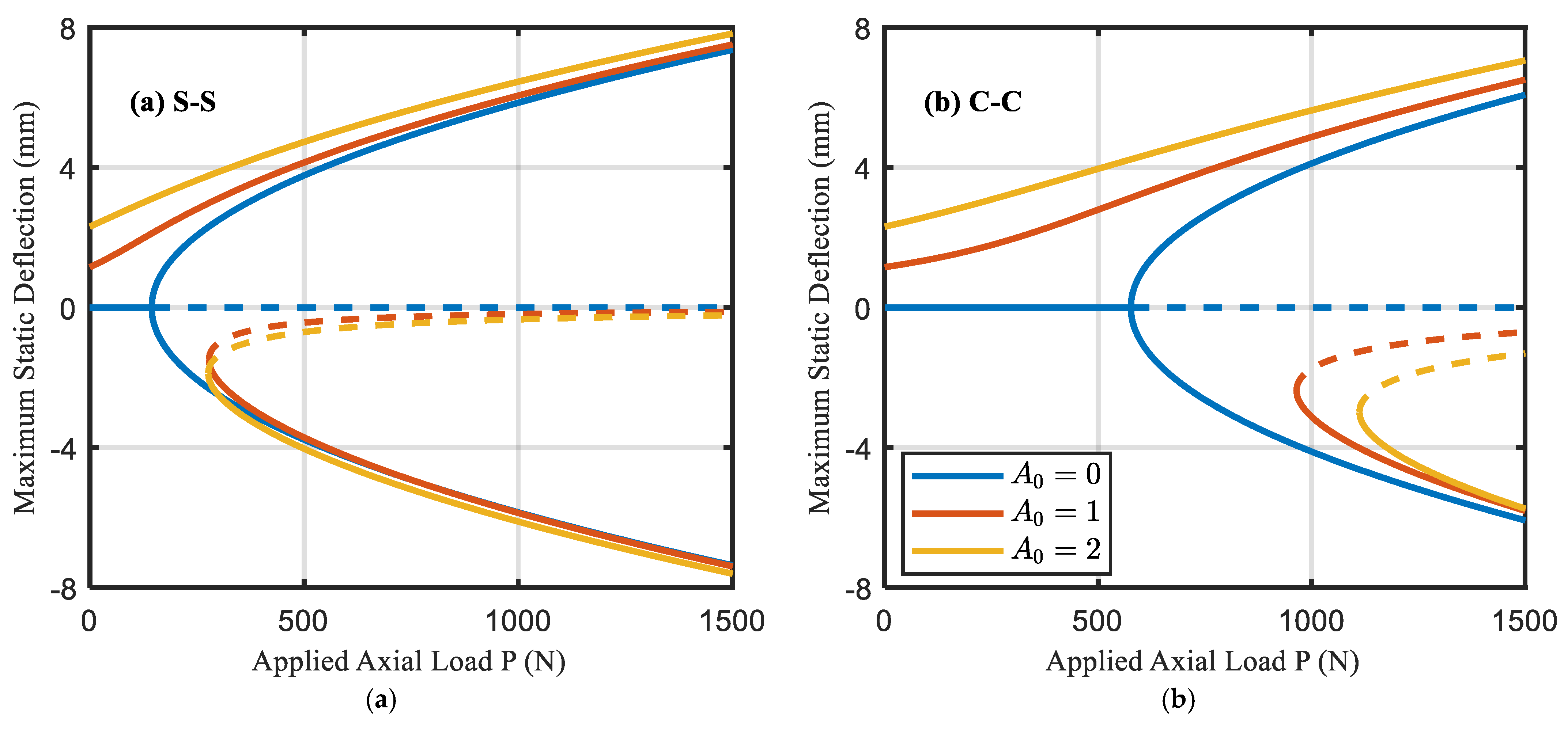
During fabrication or due to heating and cooling processes, the structure may exhibit an initial curved shape as a form of imperfection. Therefore, the initial imperfection can supposedly have the following form, which is accompanied by the first buckling mode as follows:
w 0 ( x ) = A 0 s i n ( π x )                 S - S
w 0 ( x ) = A 0 sin 2 ( π x )                 C - C
where A 0 is the amplitude of initial curvature. The boundary conditions in dimensionless form for S-S and C-C beams, respectively are as follows:
w = 0             &     w = 0         at       x = 0 ,   1
w = 0               &         w = 0           at     x = 0 ,   1

3. Numerical Solution Based on DIQM

3.1. Numerical Technique

To define the mesh grid points, the shifted Chebyshev–Gauss–Lobatto grid points are used as follows [15]:
x i = 1 2 ( 1 cos ( ( i 1 ) π N 1 ) ) ,   i = 1 ,   2 , N .
where N is the number of grid points. According to the DIQM, the first-order derivative of a continuous function y ( x ) is as follows:
d y ( x ) d x | x = x i = j = 1 N C i j y ( x j ) ,   i = 1 , 2 , N
Weighting coefficients can be evaluated as follows [40]:
C i j = { 𝒫 ( x i ) ( x i x j ) 𝒫 ( x j )           i j                             i , j = 1 , 2 , N j = 1 , i j N C i j       i = j ,                                               i = 1 , 2 , N
where
𝒫 ( x i ) = Π j = 1 , j i N ( x i x j )
From Equation (24), the first-order derivative of a function can be written in a matrix form as follows:
Y = C ( 1 )   y
where C ( 1 ) = [ C i j ] , and vector y = [ y ( x 1 )   y ( x 2 ) y ( x N ) ] T and its first derivative vector are Y = [ Y ( x 1 )   Y ( x 2 ) Y ( x N ) ] T . The higher order matrices can be obtained using the matrix multiplication as follows [24]:
  C ( n ) = C ( 1 ) C ( n 1 ) , n > 1
The definite integral of a continuous function y ( x ) over the domain can be obtained as follows:
d y d x = Y ( x )
Then
0 1 Y ( x ) d x k = 1 N ( [ K ] N k [ K ] 1 k ) Y ( x k ) = k = 1 N S k Y ( x k ) = S Y
where K is the pseudo-inverse of matrix C ( 1 ) and the row vector S = [ S 1 , S 2 , S N   ] . Additional explanations regarding the DIQM and its conversions are comprehensively presented by Equations (19) and (30).

3.2. Buckling Problem

To compute the critical buckling load and postbuckling configuration, the external transverse load q should be set to zero. Therefore, one obtains
w i v + ( P k s + γ ( w ( 1 ) w ( 0 ) w 0 ( 1 ) + w 0 ( 0 ) ) 1 2 α 0 1 ( w 2 w 0 2 ) d x ) w + k L w + k N L w 3 = w 0 i v
Equation (31) can be written as follows:
w i v + [ P k s + γ ( w ( 1 ) w ( 0 ) w 0 ( 1 ) + w 0 ( 0 ) ) Γ ] w + k L w + k N L w 3 = w 0 i v
where
Γ = 1 2 α 0 1 ( w 2 w 0 2 ) d x
As known, Equation (32) is a nonlinear nonhomogeneous fourth-order ordinary differential equation, whose exact solution is not available. Therefore, DIQM is employed to discretize Equation (33) as follows:
( C ( 4 ) + [ P k s Γ + γ ( C N 1 ( 1 ) [ w w 0 ] ) ] C ( 2 ) + k L I N ) w + k N L w 3 = C ( 4 ) w 0
Γ = 1 2 α S [ ( C ( 1 ) w ) 2 ( C ( 1 ) w 0 ) 2 ]
where I N is N × N identity matrix,   C N 1 ( 1 ) is a row matrix whose elements are the difference between the last row and the first row of matrix C ( 1 ) ,   stands for the matrix Hadamard product, and the column vector w is defined as follows:
w T = [ w 1 ,   w 2 , . , w N ]
where w i = w ( x i ) . The initial shape of imperfection w 0 ( x ) is discretized as the known vector as w 0 T = [ w 0 ( x 1 ) , w 0 ( x 2 ) , ,   w 0 ( x N )   ] .
The corresponding boundary conditions in Equation (21) can be discretized in the same manner. The system of nonlinear algebraic Equation (36) can be written as follows:
( w ,   P ) = 0
Notably, the discretized boundary conditions are appropriately substituted in the nonlinear algebraic system of Equation (37). The critical buckling load and postbuckling configuration are computed numerically using the Newton-iterative method. The solution of the linearized form of Equation (34) is used as the initial value for Newton’s method.

3.3. Bending Problem

For the static bending problem, the external axial load P is set to zero and the following equilibrium equation is obtained:
w i v ( k s γ ( w ( 1 ) w ( 0 ) w 0 ( 1 ) + w 0 ( 0 ) ) + 1 2 α 0 1 ( w 2 w 0 2 ) d x ) w + k L w + k N L w 3 w 0 i v = q ( x )
The applied transverse load q ( x ) can be expressed as follows:
q ( x ) = q 0 δ ( x x p )                                                                 Point   load q ( x ) = q 0                                                       iformly   distributed   load
where q 0 is the intensity of the load, δ ( . ) is the Dirac delta function, and x p is the application position of the point load.
It is difficult to analytically solve the nonlinear equation described in Equation (38). Therefore, the numerical DIQM is used to solve it.
In the case of point load, Equation (38) is as follows:
w i v ( k s γ ( w ( 1 ) w ( 0 ) w 0 ( 1 ) + w 0 ( 0 ) ) + 1 2 α 0 1 ( w 2 w 0 2 ) d x ) w + k L w + k N L w 3 w 0 i v = q 0 δ ( x x p )
It is well-known that the Dirac delta function has the following properties:
δ ( x x p ) = 0 , if x x p , 1 < p < N
and
δ ( x x p ) d x = 1
To use the properties of the Dirac delta function, Equation (40) is integrated over the domain [41] as follows:
0 1 [ w i v ( k s γ ( w ( 1 ) w ( 0 ) w 0 ( 1 ) + w 0 ( 0 ) ) + 1 2 α 0 1 ( w 2 w 0 2 ) d x ) w + k L w + k N L w 3 w 0 i v ] d x = q 0
The left-hand side of Equation (43) is integrated numerically using the integral operator defined in Equation (30), as follows:
i = 1 N S i [ w i v ( x i ) ( k s γ ( w ( 1 ) w ( 0 ) w 0 ( 1 ) + w 0 ( 0 ) ) + 1 2 α 0 1 ( [ w ( x i ) ] 2 [ w 0 ( x i ) ] 2 ) d x ) w ( x i ) + k L w ( x i ) + k N L [ w ( x i ) ] 3 w 0 i v ( x i ) ] = q 0
Using Equation (41), Equation (44) can be simplified to the following:
w i v ( x i ) ( k s γ ( w ( 1 ) w ( 0 ) w 0 ( 1 ) + w 0 ( 0 ) ) + 1 2 α 0 1 ( [ w ( x i ) ] 2 [ w 0 ( x i ) ] 2 ) d x ) w ( x i ) + k L w ( x i ) + k N L [ w ( x i ) ] 3 w 0 i v ( x i ) = { q 0 S p   i f   i = p 0         i f   i p
Discretizing Equation (45) by DIQM, the results in the matrix form are as follows:
( C ( 4 ) [ k s γ ( C N 1 ( 1 ) [ w w 0 ] ) + 1 2 α S [ ( C ( 1 ) w ) 2 ( C ( 1 ) w 0 ) 2 ] ] C ( 2 ) + k L I N ) w + k N L w 3 C ( 4 ) w 0 = F q
where
F q = { q 0 S p   i f   i = p 0         i f   i p
Using the uniform load rather than the point load in Equation (40), the function F q can be computed as follows:
F q = [ q 0 q 0 q 0 ] N × 1

4. Numerical Results

In this section, the numerical results for buckling and nonlinear bending behaviors of perfect and imperfect helicoidal composite beams embedded on elastic foundations are investigated. First, a comparison is carried out to show the validity of the present model. Second, parametric studies are presented to illustrate the significance of helicoidal rotation angle, imperfection amplitude, and elastic foundation constants on buckling, postbuckling, and bending behaviors of helicoidal composite beams.

4.1. Validation

To verify the accuracy of the present method, the numerical results for nonlinear buckling and postbuckling configurations of composite beams obtained by the present model are compared with those in the literature. Herein, the critical buckling load and postbuckling configuration of perfect and imperfect composite beams are compared with the analytical solutions presented by Emam and Nayfeh [18] and Emam [17]. For comparison purposes, the beam with six layers has the following bulk and material properties:
E 1 = 155   Gpa ,   E 2 = 12.1   Gpa ,   G 12 = 4.4   Gpa ,   ν = 0.248 ,   ρ = 1560   kg / m 3
h = 1   mm ,   b = 10   mm ,   L = 250   h
The following layups have been considered [18]: Unidirectional laminate ( [ 0 / 0 / 0 ] s ), [ 0 90 90 ] s laminate, [ 90 / 90 / 0 ] s laminate, and cross-ply laminate ( [ 90 / 90 90 ] s ).
In Table 1, the first three buckling loads of S-S and C-C perfect composite beams with different layups are tabulated and compared with those reported [18]. Moreover, Table 2 presents a comparison of the first buckling load of C-C imperfect composite beams for different laminates. The load–deflection response associated with postbuckling behaviors of C-C perfect and imperfect composite beams for different layups are compared with those obtained by [17], as shown in Figure 1. The excellent agreement with Refs. [17,18] can be observed, which confirm the validity of the present beam model and solution methodology.

4.2. Parametric Studies

In this study, the material properties of Jiang et al. [4] are used, as presented in Table 3. Here, it is assumed that L = 100 h . Table 4 presents the specifications of the selected layup configurations. Unidirectional and quasi-isotropic laminates are used as references.

4.2.1. Buckling Analysis

Table 5 tabulates the critical buckling load of S-S and C-C perfect and imperfect composite beams with different layup specifications and various values of imperfection amplitude. As concluded in the case of imperfection amplitude A 0 3 , the smallest buckling load is observed in the case of HE3 configuration, and the highest buckling load is observed in the case of UD configuration, which has the largest buckling stiffness due to the ability of UD to resist an axial load that is aligned with its orientation (i.e., A and D stiffness have the largest values in the case of UD and smallest values in the case of HE3). The lamination schemes can be arranged in descending order, according to the buckling stiffness, as follows: UD, HR1, HE1, HR2, HR3, HE2, QI, and HE3, respectively. In the case of A 0 = 4 , the optimum configuration that can sustain the largest buckling load is HR3. However, the UD has a null load solution and QI has a negative buckling load.
Variations of the critical buckling load with the dimensionless imperfection amplitude at different layup specifications are presented in Figure 2. As compared with the UD layup, the HR and HE layups with small rotation angles can improve the critical buckling load.
Figure 3 displays the influence of elastic foundation constants on the critical buckling load of S-S and C-C perfect and imperfect helicoidal composite beams with layup sequences HR1 and HE1. It can be observed that an increase in both shear and linear foundation constants leads to an increase in the buckling load of perfect and imperfect helicoidal composite beams. On the other hand, an increase in the nonlinear foundation constants leads to an increase in the buckling load of imperfect beams and has no effect on the buckling load of perfect beams. Furthermore, it can be interpreted that the effect of shear parameter on the buckling load is more prominent than the effect of linear and nonlinear foundation constants.
Figure 4 demonstrates the nonlinear response in prebuckling and postbuckling states of helicoidal composite beams with layup sequence HR1 for various values of imperfection amplitude. The solid lines indicate stable paths, while the dotted lines indicate unstable ones. As opposed to the perfect beams, which show a pitchfork bifurcation, the buckling of imperfect beams exhibits a snap-through behavior. For the perfect beam, a zero equilibrium path is observed in the prebuckling region ( P < P c r ). Herein, P c r is the bifurcation point. At critical buckling load P c r , the beam loses its stability, and two symmetrical nonzero stable paths emerge. In snap-through buckling, at each value of the applied axial load P , the composite beam has a nonzero solution. In addition to the primary solution, two secondary solutions appear at P = P c r . Herein, P c r represents the turning point connecting the secondary solutions.
In Figure 5, the load–deflection curves associated with the postbuckling response of S-S and C-C perfect helicoidal composite beams are displayed. It can be observed that the rotation angle of helicoidal composite beams has a great influence on the postbuckling response. For smaller values of axial load, the maximum deflection of HE1 and HE2 is smaller than the maximum deflection of HR1 and HR3, respectively. However, as the axial load increases, this trend is reversed.
Figure 6 and Figure 7 present the load–deflection curves of imperfect helicoidal composite beams in the prebuckling and postbuckling domains of S-S and C-C boundary conditions, respectively. It can be observed that the rotation angle of helicoidal composite beams has a great influence on the buckling response.

4.2.2. Bending Analysis

Herein, the dimensionless load parameter q 0 is defined as follows:
q 0 = q ^ 0 L 4 r b ( D 11 B 11 2 A 11 )                             for   uniform   load   and  
q 0 = q ^ 0 L 3 r b ( D 11 B 11 2 A 11 )                     for   point   load
Table 6 and Table 7 present the value of imposed force amplitude in the case of uniform and point loads that provide the maximum definite deflection at different layup configurations without elastic foundation effects. It can be observed that to impose the definite deflection ( w m a x = 0.1   mm ) for all of the configurations, the UD and HR1 need higher loads than the other configurations. This indicates that the rigidity of UD and HR1 is higher as compared with the other configurations for both C-C and S-S supports. However, HE3 and HR1 are more flexible than the other configurations, which indicates that a small load can be applied to deflect the beam by 0.1 mm. For the same configuration and imposed deflection, the rigidity of C-C beam is higher than the S-S beam by around five times.
In Figure 8 and Figure 9, the load–deflection curves associated with the nonlinear bending response of S-S and C-C perfect and imperfect composite beams under the uniform lateral load with different layups are displayed. It can be observed that the rotation angle of helicoidal composite beams and the imperfection amplitude lead to a change in the trend of load–deflection response. In the case of perfect beams, the maximum deflection of HR1 is higher than the maximum deflection of HE1, and the maximum deflection of HR3 is higher than the maximum deflection of HE3. The reverse occurs for imperfect beams. These observations are valid for S-S and C-C boundary conditions.
The effect of elastic foundations on the nonlinear bending curves of helicoidal composite beams subjected to the point load with layup specification HR1 are studied in Figure 10. It can be observed that at a given applied lateral load, the maximum deflection becomes smaller as the elastic foundation coefficients increase. Comparing the effects of elastic foundations on different boundary conditions shows that the influence of elastic foundation coefficients is more effective on S-S helicoidal composite beams.

5. Concluding Remarks

This study presents a numerical analysis for the buckling, postbuckling, and nonlinear bending response of helicoidal composite perfect and imperfect beams. Herein, S-S and C-C boundary conditions are considered. Verification studies indicate that the DIQM is an accurate method for the analysis of buckling and postbuckling behaviors of imperfect beams. Several numerical results are presented to study the influence of helicoidal rotation angle, amplitude of initial imperfection, and elastic foundation coefficients on nonlinear bending, buckling, and postbuckling behaviors of composite beams. From the numerical results, the main conclusions are summarized as follows:
  • For large values of imperfection amplitude, HR and HE layups enhanced the critical buckling load.
  • The perfect beam buckles through a pitchfork bifurcation. However, the imperfect beam snaps through the buckling type.
  • The rotation angle of helicoidal composite beams reversed the trend of postbuckling response.
  • In the case of A 0 = 4 , the optimum configuration that can sustain the largest buckling load is HR3. However, the UD has a null load solution and QI has a negative buckling load.
  • An increase in the nonlinear foundation constant leads to an increase in the buckling load of imperfect beams and has no effect on the buckling load of perfect beams.
  • The rigidity of UD and HR1 is higher than the other configurations for both C-C and S-S supports. However, HE3 and HR1 are more flexible than the other configurations.
  • For the same configuration and imposed deflection, the rigidity of C-C beam is higher than the S-S beam by around five times.
  • The proposed model can be used in the design and analysis of aerospace, naval, vehicles, and biomedical structures, which are manufactured from specific, high-strength, composite laminated perfect and curved beams.

Author Contributions

Conceptualization, M.A.E.; formal analysis, N.M. and S.A.M.; funding acquisition, M.A.E.; investigation, N.M., S.A.M. and M.A.E.; methodology, N.M. and S.A.M.; resources, M.A.E.; software, N.M. and S.A.M.; writing—the original draft, N.M.; writing—review & editing, S.A.M. and M.A.E. All authors have read and agreed to the published version of the manuscript.

Funding

This research work was funded by Institutional Fund Projects, grant number IFPIP: 10-135-1442). Therefore, the authors gratefully acknowledge the technical and financial support from the ministry of Education and King Abdulaziz University, DSR, Jeddah, Saudi Arabia.

Institutional Review Board Statement

Not applicable.

Informed Consent Statement

Not applicable.

Data Availability Statement

Not applicable.

Conflicts of Interest

The authors declare no conflict of interest.

References

  1. Cheng, L.; Thomas, A.; Glancey, J.L.; Karlsson, A.M. Mechanical behavior of bio-inspired laminated composites. Compos. Part A Appl. Sci. Manuf. 2011, 42, 211–220. [Google Scholar] [CrossRef] [Green Version]
  2. Apichattrabrut, T.; Ravi-Chandar, K. Helicoidal composites. Mech. Adv. Mater. Struct. 2006, 13, 61–76. [Google Scholar] [CrossRef]
  3. Liu, J.L.; Lee, H.P.; Tan VB, C. Effects of inter-ply angles on the failure mechanisms in bioinspired helicoidal laminates. Compos. Sci. Technol. 2018, 165, 282–289. [Google Scholar] [CrossRef]
  4. Jiang, H.; Ren, Y.; Liu, Z.; Zhang, S.; Lin, Z. Low-velocity impact resistance behaviors of bio-inspired helicoidal composite laminates with non-linear rotation angle-based layups. Compos. Struct. 2019, 214, 463–475. [Google Scholar] [CrossRef]
  5. Eltaher, M.A.; Mohamed, S.C.; Melaibari, A.A. Static stability of a unified composite beams under varying axial loads. Thin-Walled Struct. 2020, 147, 106488. [Google Scholar] [CrossRef]
  6. Shang, J.S.; Ngern, N.H.; Tan, V.B. Crustacean-inspired helicoidal laminates. Compos. Sci. Technol. 2016, 128, 222–232. [Google Scholar] [CrossRef]
  7. Grunenfelder, L.K.; Suksangpanya, N.; Salinas, C.; Milliron, G.; Yaraghi, N.; Herrera, S.; Kisailus, D. Bio-inspired impact-resistant composites. Acta Biomater. 2014, 10, 3997–4008. [Google Scholar] [CrossRef]
  8. Ginzburg, D.; Pinto, F.; Iervolino, O.; Meo, M. Damage tolerance of bio-inspired helicoidal composites under low velocity impact. Compos. Struct. 2017, 161, 187–203. [Google Scholar] [CrossRef] [Green Version]
  9. Yang, F.; Xie, W.; Meng, S. Global sensitivity analysis of low-velocity impact response of bio-inspired helicoidal laminates. Int. J. Mech. Sci. 2020, 187, 106110. [Google Scholar] [CrossRef]
  10. Golewski, G.L. On the special construction and materials conditions reducing the negative impact of vibrations on concrete structures. Mater. Today Proc. 2021, 45, 4344–4348. [Google Scholar] [CrossRef]
  11. Gul, U.; Aydogdu, M. A micro/nano-scale Timoshenko-Ehrenfest beam model for bending, buckling and vibration analyses based on doublet mechanics theory. Eur. J. Mech.-A/Solids 2021, 86, 104199. [Google Scholar] [CrossRef]
  12. Yang, F.; Xie, W.; Meng, S. Crack-driving force and toughening mechanism in crustacean-inspired helicoidal structures. Int. J. Solids Struct. 2021, 208, 107–118. [Google Scholar] [CrossRef]
  13. Yin, S.; Yang, R.; Huang, Y.; Guo, W.; Chen, D.; Zhang, W.; Xu, J. Toughening mechanism of coelacanth-fish-inspired double-helicoidal composites. Compos. Sci. Technol. 2021, 205, 108650. [Google Scholar] [CrossRef]
  14. Lyratzakis, A.; Tsompanakis, Y.; Psarropoulos, P.N. Efficient mitigation of high-speed train vibrations on adjacent reinforced concrete buildings. Constr. Build. Mater. 2022, 314, 125653. [Google Scholar] [CrossRef]
  15. Eltaher, M.A.; Mohamed, N.; Mohamed, S.A.; Seddek, L.F. Periodic and nonperiodic modes of postbuckling and nonlinear vibration of beams attached to nonlinear foundations. Appl. Math. Model. 2019, 75, 414–445. [Google Scholar] [CrossRef]
  16. Lacarbonara, W.; Arafat, H.N.; Nayfeh, A.H. Non-linear interactions in imperfect beams at veering. Int. J. Non-Linear Mech. 2005, 40, 987–1003. [Google Scholar] [CrossRef]
  17. Emam, S.A. A static and dynamic analysis of the postbuckling of geometrically imperfect composite beams. Compos. Struct. 2009, 90, 247–253. [Google Scholar] [CrossRef]
  18. Emam, S.A.; Nayfeh, A.H. Postbuckling and free vibrations of composite beams. Compos. Struct. 2009, 88, 636–642. [Google Scholar] [CrossRef]
  19. Gupta, R.K.; Gunda, J.B.; Janardhan, G.R.; Rao, G.V. Post-buckling analysis of composite beams: Simple and accurate closed-form expressions. Compos. Struct. 2010, 92, 1947–1956. [Google Scholar] [CrossRef]
  20. Gunda, J.B.; Gupta, R.K.; Janardhan, G.R.; Rao, G.V. Large amplitude vibration analysis of composite beams: Simple closed-form solutions. Compos. Struct. 2011, 93, 870–879. [Google Scholar] [CrossRef]
  21. Li, Z.M.; Qiao, P. Buckling and postbuckling behavior of shear deformable anisotropic laminated beams with initial geometric imperfections subjected to axial compression. Eng. Struct. 2015, 85, 277–292. [Google Scholar] [CrossRef]
  22. Emam, S.; Eltaher, M.A. Buckling and postbuckling of composite beams in hygrothermal environments. Compos. Struct. 2016, 152, 665–675. [Google Scholar] [CrossRef]
  23. Emam, S.A.; Eltaher, M.A.; Khater, M.E.; Abdalla, W.S. Postbuckling and free vibration of multilayer imperfect nanobeams under a pre-stress load. Appl. Sci. 2018, 8, 2238. [Google Scholar] [CrossRef] [Green Version]
  24. Mohamed, N.; Eltaher, M.A.; Mohamed, S.A.; Seddek, L.F. Numerical analysis of nonlinear free and forced vibrations of buckled curved beams resting on nonlinear elastic foundations. Int. J. Non-Linear Mech. 2018, 101, 157–173. [Google Scholar] [CrossRef]
  25. Guo, J.; Shi, D.; Wang, Q.; Pang, F.; Liang, Q. Domain decomposition approach for static and dynamic analysis of composite laminated curved beam with general elastic restrains. Mech. Adv. Mater. Struct. 2019, 26, 1390–1402. [Google Scholar] [CrossRef]
  26. Wang, Y.; Feng, C.; Santiuste, C.; Zhao, Z.; Yang, J. Buckling and postbuckling of dielectric composite beam reinforced with Graphene Platelets (GPLs). Aerosp. Sci. Technol. 2019, 91, 208–218. [Google Scholar] [CrossRef]
  27. Yang, Z.; Feng, C.; Yang, J.; Wang, Y.; Lv, J.; Liu, A.; Fu, J. Geometrically nonlinear buckling of graphene platelets reinforced dielectric composite (GPLRDC) arches with rotational end restraints. Aerosp. Sci. Technol. 2020, 107, 106326. [Google Scholar] [CrossRef]
  28. Mohamed, N.; Eltaher, M.A.; Mohamed, S.A.; Seddek, L.F. Energy equivalent model in analysis of postbuckling of imperfect carbon nanotubes resting on nonlinear elastic foundation. Struct. Eng. Mech. 2019, 70, 737–750. [Google Scholar] [CrossRef]
  29. Mohamed, N.; Mohamed, S.A.; Eltaher, M.A. Buckling and post-buckling behaviors of higher order carbon nanotubes using energy-equivalent model. Eng. Comput. 2021, 37, 2823–2836. [Google Scholar] [CrossRef]
  30. Eltaher, M.A.; Mohamed, N. Nonlinear stability and vibration of imperfect CNTs by doublet mechanics. Appl. Math. Comput. 2020, 382, 125311. [Google Scholar] [CrossRef]
  31. Eltaher, M.A.; Mohamed, N.; Mohamed, S.A. Nonlinear buckling and free vibration of curved CNTs by doublet mechanics. Smart Struct. Syst. 2020, 26, 213–226. [Google Scholar] [CrossRef]
  32. Song, Z.; Li, W.; He, X.; Xie, D. Comparisons of matched interface and boundary (MIB) method and its interpolation formulation for free vibration analysis of stepped beams and plates. Appl. Math. Comput. 2021, 394, 125817. [Google Scholar] [CrossRef]
  33. Emam, S.; Lacarbonara, W. Buckling and postbuckling of extensible, shear-deformable beams: Some exact solutions and new insights. Int. J. Non-Linear Mech. 2021, 129, 103667. [Google Scholar] [CrossRef]
  34. Boutahar, Y.; Lebaal, N.; Bassir, D. A Refined Theory for Bending Vibratory Analysis of Thick Functionally Graded Beams. Mathematics 2021, 9, 1422. [Google Scholar] [CrossRef]
  35. Zhang, P.; Ma, J.; Duan, M.; Yuan, Y.; Wang, J. A high-precision curvature constrained Bernoulli–Euler planar beam element for geometrically nonlinear analysis. Appl. Math. Comput. 2021, 397, 125986. [Google Scholar] [CrossRef]
  36. Almitani, K.H.; Mohamed, N.; Alazwari, M.A.; Mohamed, S.A.; Eltaher, M.A. Exact Solution of Nonlinear Behaviors of Imperfect Bioinspired Helicoidal Composite Beams Resting on Elastic Foundations. Mathematics 2022, 10, 887. [Google Scholar] [CrossRef]
  37. Karamanli, A.; Vo, T.P. Finite element model for free vibration analysis of curved zigzag nanobeams. Compos. Struct. 2022, 282, 115097. [Google Scholar] [CrossRef]
  38. Dabbagh, A.; Rastgoo, A.; Ebrahimi, F. Post-buckling analysis of imperfect multi-scale hybrid nanocomposite beams rested on a nonlinear stiff substrate. Eng. Comput. 2022, 38, 301–314. [Google Scholar] [CrossRef]
  39. Aydogdu, M. Thermal buckling analysis of cross-ply laminated composite beams with general boundary conditions. Compos. Sci. Technol. 2007, 67, 1096–1104. [Google Scholar] [CrossRef]
  40. Quan, J.R.; Chang, C.T. New insights in solving distributed system equations by the quadrature method—I. Analysis. Comput. Chem. Eng. 1989, 13, 779–788. [Google Scholar] [CrossRef]
  41. Eftekhari, S.A. A note on mathematical treatment of the Dirac-delta function in the differential quadrature bending and forced vibration analysis of beams and rectangular plates subjected to concentrated loads. Appl. Math. Model. 2015, 39, 6223–6242. [Google Scholar] [CrossRef]
Figure 1. Comparison of load–deflection curves associated with the postbuckling configuration of C-C perfect and imperfect composite beams with ( k L = k N l = k s = 0 ) for (a) unidirectional laminate (b) [90,90,0]s laminates (c) [0,90,90]s laminate, and (d) Cross-ply laminate.
Mathematics 10 01084 g001
Figure 2. Variations of the critical buckling load with the imperfection amplitude of S-S and C-C beams for different layup specifications ( k L = k N l = k s = 0 ,   L = 100 h ). (a) Helicoidal recursive laminates; (b) helicoidal exponential laminates.
Mathematics 10 01084 g002aMathematics 10 01084 g002b
Figure 3. Effect of elastic foundation constants on the critical buckling load of S-S and C-C perfect and imperfect helicoidal composite beams with layup sequences HR1 and HE1,   L = 100 h . (a) k N l = k s = 0 ; (b) k L = k s = 0 ; (c) k N l = k L = 0 .
Mathematics 10 01084 g003aMathematics 10 01084 g003b
Figure 4. Load–deflection response of S-S and C-C helicoidal composite beams with layup specification HR1 with different values of imperfection amplitude ( k L = k N L = k s = 0 ,   L = 100 h ) for (a) S-S supported beam; and (b) C-C Supported beam.
Mathematics 10 01084 g004
Figure 5. Postbuckling configuration of S-S and C-C perfect composite beams with various layup specifications for (a) S-S supported beam; and (b) C-C Supported beam.
Mathematics 10 01084 g005
Figure 6. Load–deflection response of S-S imperfect composite beams associated with the postbuckling analysis with different layups ( A 0 = 2 ,   k L = k N l = k s = 0 ,   L = 100 h ).
Mathematics 10 01084 g006
Figure 7. Load–deflection response of C-C imperfect composite beams associated with the postbuckling analysis with different layups ( A 0 = 4 ,   k L = k N l = k s = 0 ,   L = 100 h ).
Mathematics 10 01084 g007
Figure 8. Load–deflection bending response of S-S perfect and imperfect composite beams with different layups ( k L = k N l = k s = 0 ,   L = 100 h ) for (a) Perfect beam; (b) Imperfect beam.
Mathematics 10 01084 g008
Figure 9. Load–deflection nonlinear bending response of C-C perfect and imperfect composite beams with different layups ( k L = k N l = k s = 0 ,   L = 100 h ) for (a) Perfect beam; (b) Imperfect beam.
Mathematics 10 01084 g009
Figure 10. Effect of elastic foundations on the nonlinear bending response of S-S and C-C perfect and imperfect helicoidal composite beams with layup sequence HR1 ( x p = 0.5 ,   L = 100 h ) . (a) k N l = k s = 0 ; (b) k L = k s = 0 ; (c) k L = k N L = 0 .
Mathematics 10 01084 g010aMathematics 10 01084 g010b
Table 1. Validation of the first three buckling loads for different laminates of S-S and C-C perfect composite beams.
B. CsLaminate P c r 1 P c r 2 P c r 3
S-SUnidirectionalPresent20.4956181.98239184.46030
Ref. [18]20.4955981.98235184.46029
[ 0 90 90 ] s Present14.8969059.58758134.07201
Ref. [18]14.8968959.58755134.07200
[ 90 / 90 / 0 ] s Present2.299829.1992720.69834
Ref. [18]2.299829.1992620.69834
[ 90 / 90 90 ] s Present1.599986.3999214.39980
Ref. [18]1.599986.3999114.39980
C-CUnidirectionalPresent81.98239167.71528327.92943
Ref. [18]81.98235167.71539327.92940
[ 0 90 90 ] s Present59.58758121.90116238.35024
Ref. [18]59.58755121.90124238.35021
[ 90 / 90 / 0 ] s Present9.1992718.8193836.79705
Ref. [18]9.1992618.8193936.79705
[ 90 / 90 90 ] s Present6.3999213.0926125.59965
Ref. [18]6.3999113.0926225.59965
Table 2. Validation of the first buckling load for different laminates of C-C imperfect composite beams.
Laminate A 0   =   0.5 A 0   =   1 A 0   =   2 A 0   =   4
UnidirectionalPresent119.43563138.34523159.09092154.93696
Ref. [17]119.43561138.34522159.09091154.93693
[ 0 90 90 ] s Present81.8805493.78445109.10775119.14004
Ref. [17]81.8805393.78445109.10775119.14002
[ 90 / 90 / 0 ] s Present15.2632117.6341817.824873.83562
Ref. [17]15.2632117.6341817.824873.83561
[ 90 / 90 90 ] s Present9.3236810.7998512.4193612.09508
Ref. [17]9.3236810.7998512.4193612.09508
Table 3. Material and bulk properties.
Material PropertiesBulk Properties
E 1 ( G p a ) E 2 ( G p a ) G 12 ( G p a ) ν 12 h   ( m m ) b   ( m m )
1107.8400.3244
Table 4. Specifications of the selected layup configurations.
Designation N L Stacking SequenceDescription
UD20[0 0 …   0]Unidirectional
QI20 [ 45 45 0 90   ] 4 s Quasi isotropic-symmetric
Helicoidal recursive rotation angle [ θ 0 / θ 1   / θ i   ] s = [ θ i 1 + ( i 1 ) δ θ   ] s ,   θ 0 = 0 ,   2 i N L 2
HR120 [ 0 / 1 / 3 / 6 / 10 / 15 / 21 / 28 / 36 / 45   ] s   Helicoidal recursive δ θ   = 1
HR220 [ 0 / 2 / 6 / 12 / 20 / 30 / 42 / 56 / 72 / 90   ] s Helicoidal recursive δ θ   = 2
HR320 [ 0 / 3 / 9 / 18 / 30 / 45 / 63 / 84 / 108 / 135   ] s Helicoidal recursive δ θ   = 3
Helicoidal exponential rotation angle [ θ 0 / θ 1   / θ i ] 2 s = [ δ θ i   ] 2 s ,     1 i N L 4
HE120 [ 2 / 4 / 8 / 16 / 32   ] 2 s Helicoidal exponential δ θ   = 2
HE220 [ 2.5 / 6.3 / 15.6 / 39 / 97.7   ] 2 s Helicoidal exponential δ θ   = 2.5
HE320 [ 3 / 9 / 27 / 81 / 243   ] 2 s Helicoidal exponential δ θ   = 3
Table 5. Critical buckling load ( N ) of perfect and imperfect composite beams for different layups ( k s = k L = k N L = 0 ,   L = 100 h ) .
UDQIHR1HR2HR3HE1HE2HE3
(a) S-S
A 0 = 0 145.81310120.72637144.09638138.83241132.22192142.24365127.06791115.41052
A 0 = 1 282.95747234.85871277.94718263.02879250.01282275.55741243.78870220.66353
A 0 = 2 275.56948226.61496276.10620273.03692260.52639269.97792245.86962224.49128
A 0 = 4 0−12.3262031.78741100.08881101.185869.4574049.7302756.57246
(b) C-C
A 0 = 0 583.25210482.90523576.38524555.32939528.88744568.97431508.27138461.64186
A 0 = 1 984.23755817.92713964.35848907.93767862.66569957.75002844.26936763.39956
A 0 = 2 1131.8299939.43441111.78901052.11521000.05081102.2291975.1543882.6541
A 0 = 4 1102.2771906.45961104.42421092.14771042.10581079.9117983.4782897.9644
Table 6. Uniform load q ^ 0 ( N / m ) applied to perfect composite beams for different layups and maximum deflection value ( k L = k s = k N L = 0 ).
UDQIHR1HR2HR3HE1HE2HE3
(a) w m a x = 0.1   mm
S-S0.71060.58840.70230.67610.64390.69320.61930.5620
C-C3.54842.93793.50663.37853.21763.46153.09222.8085
(b) w m a x = 0.3   mm
S-S2.16391.79252.13582.05171.95352.10991.88151.7081
C-C10.68148.843710.552410.15769.674010.41889.30268.4492
Table 7. Point load parameter q ^ 0 ( N ) applied to perfect composite beams for different layups and maximum deflection value ( k L = k s = k N L = 0 ).
UDQIHR1HR2HR3HE1HE2HE3
(a) w m a x = 0.1   mm
S-S0.17760.14710.17550.16900.16100.17320.15470.1405
C-C0.70970.58760.70130.67570.64350.69230.61840.5617
(b) w m a x = 0.3   mm
S-S0.54060.44770.53360.51270.48810.52710.47000.4267
C-C2.13671.76912.11072.03241.93562.08441.86131.6902
Publisher’s Note: MDPI stays neutral with regard to jurisdictional claims in published maps and institutional affiliations.

