Article

Performance Optimization of a Thermoelectric Device by Using a Shear Thinning Nanofluid and Rotating Cylinder in a Cavity with Ventilation Ports

1
Department of Mechanical Engineering, College of Engineering, University of Ha’il, Ha’il City 81451, Saudi Arabia
2
Laboratory of Thermal and Energetic Systems Studies, National School of Engineering of Monastir, University of Monastir, Monastir City 5000, Tunisia
3
Department of Mechanical Engineering, Celal Bayar University, 45140 Manisa, Turkey
4
Laboratory of Metrology and Energy Systems, University of Monastir, Monastir City 5000, Tunisia
5
Materials, Energy and Renewable Energies Research Unit, Faculty of Sciences, University of Gafsa, Gafsa 2112, Tunisia
6
Laboratory of Electro-Mechanical Systems (LASEM), National Engineering School of Sfax, University of Sfax, Sfax 3038, Tunisia
7
Laboratoire de Recherche en Thermique et Thermodynamique des Procedes Industriels, Ecole Nationale d’Ingenieurs de Monastir, Av. Ibn Jazzar, Monastir City 5060, Tunisia
*
Author to whom correspondence should be addressed.
Mathematics 2022, 10(7), 1075; https://doi.org/10.3390/math10071075
Submission received: 20 February 2022 / Revised: 17 March 2022 / Accepted: 22 March 2022 / Published: 27 March 2022
(This article belongs to the Special Issue Computational Fluid Dynamics II)

Abstract

:
The combined effects of using a rotating cylinder and shear thinning nanofluid on the performance improvements of a thermoelectric generator (TEG)-installed cavity with multiple ventilation ports are numerically assessed. An optimization algorithm is used to find the best location, rotational speed and size of the cylinder to deliver the highest power generation of the TEG. The power generation features with varying Rew are different for the first nanofluid (NF1) when compared to the second one (NF2). The power rises with higher Rew when NF1 is used, and up to 49% enhancement is obtained. The output power variation between nanofluids NF1 and NF2 is the highest at Rew = 0, which is obtained as 68.5%. When the cylinder location is varied, the change in the output power becomes 61% when NF2 is used. The optimum case has 11.5%- and 161%-higher generated power when compared with the no-object case with NF1 and NF2. The computational effort of using the high-fidelity coupled system is reduced when optimization is considered.

1. Introduction

Convective heat transfer (HT) in cavities with ports is relevant in many different engineering systems, including building ventilation, convective drying, electronic cooling, solar power applications, thermal energy storage and many others. The inclusion of multiple vented ports in cavities results in complex flow regimes, and many re-circulations are established [1,2]. Many studies have considered the convective HT performance for vented cavities. The location of the ports and Reynolds number (Re) were found to be effective regarding the flow and HT characteristics [3,4,5].
Many different enhancement techniques have been offered for convective HT in ventilated cavities, including the use of fins [6], flexible walls [7], magnetic fields [8,9] and flow pulsation [10,11,12]. In one of the methods, rotating cylinders have been used in channels/cavities for convective HT control [13,14,15,16]. The location, size, conductivity ratio and rotational speed have been considered as the most influential parameters that affect the HT [17,18,19,20,21,22].
There are a few studies that considered the impacts of rotating cylinders in 3D cavity configurations [23,24,25,26]. Another method that can be used to control the convection for ventilated cavities is the utilization of nanofluids. The theory and applications of nanofluids in thermal engineering systems have been reviewed in many studies [27,28,29,30,31,32,33,34,35]. The accurate modeling of nanofluid behavior requires good representation of the thermophysical properties and simulation tools. Non-Newtonian behavior of nanofluids in different thermal systems has been considered in various studies [36,37,38,39,40,41,42,43].
Currently, the need for alternative energy sources is growing due to energy costs and environmental side impacts. Thermoelectric generators (TEGs) are considered as one of the alternatives for thermoelectric energy conversion. They offer many advantages, such as having no moving parts, being compact and working quietly [44,45]. They have been used in many energy system applications, including military, solar and refrigeration [46]. They can also be used as control elements for thermal management in various systems.
Performance improvements for renewable energy systems may be enhanced by using TE devices [47,48,49]. The power generation characteristics of these devices depend on many factors, including the material properties and operating conditions of the installed system [50,51,52,53,54]. Applications of nanofluids with TEG-integrated systems have been considered in various studies, while the potential of using nanofluids has been explored [55,56,57,58]. Simulation studies of TEG-installed systems with computational fluid dynamics (CFD) are used to analyze the system performance and to determine the influencing parameters of interest.
The computations may be expansive due to the coupled physics of systems with different-length scales in 3D where TEG is considered as a sub-system. Therefore, methods are needed to increase the computational efficiency and performance estimation of TEG-integrated systems. Artificial neural networks and other soft computing techniques may be considered as one of the available options that are widely used in energy system technologies [59,60,61,62,63,64,65]. In CFD applications, parametric variations of the variables on the performance features are explored.
The optimum conditions for the operating parameters of interest may not be obtained when using only parametric CFD. Optimization routines should be used with CFD. As the computational cost of coupled multi-physics systems involving multiple time and length scales is expensive, the importance of optimization routines in CFD becomes apparent in order to achieve the best system performance. In a recent study, optimization was integrated for CFD simulation of convective drying [66]. Machine-learning methods have been used in TEG-integrated systems [67,68,69,70,71,72,73].
The present study aims to analyze the performance characteristics of TEG-integrated cavities with multiple vented ports in 3D using CFD. A rotating cylinder is placed within the vented cavity, and optimization-based analysis is performed to find the best operating parameters in order to achieve the highest power generation from the system. Comparisons are made with the parametric CFD and with the case of no-object configuration. A shear thinning nanofluid is used as the HT fluid, while the rheological properties of nanofluids are taken from an experimental study. The coupled multi-physics system of the TEG-installed system is analyzed using the finite element method and COBYLA optimization algorithm, and two different shear thinning nanofluids are utilized.
As many different applications of vented cavity configurations are available in various energy system technologies as mentioned before, a practical application of power generation with TEG installation is proposed, while performance improvement is further enhanced by using nanofluids and rotating cylinders. In the literature, the utilization of nanoparticle loading in the base fluid has been considered for thermo-electric conversion in vented cavities, and other methods of performance improvement have been used; however, the non-Newtonian aspects of nanofluids have never been considered with optimization.
The best cylinder location, size and rotational speed are found by using the optimization to deliver the highest power generation. The proposed method of CFD-based optimization is also novel in order to increase the computational efficiency of high-fidelity CFD for TEG-installed systems and to find the optimum parameters for the best performance.

2. Mathematical Modeling

2.1. System Configuration

The combined impacts of using a rotating cylinder and shear thinning nanofluid on the performance characteristics of TEG-mounted cavities with multiple ventilation ports are numerically assessed. One inlet port and two outlet ports are considered, and the port sizes are termed di and do for the inlet and outlets as shown in Figure 1. The sizes of the cavity are termed Hm and Lm. The cylinder has a radius of R and is rotating with a speed of Ω . The center location is (yc, zc). Hot fluid with a temperature of Th and a velocity of uh enters the ventilated cavity (VC), while a TEG device is mounted on the bottom surface of the VC.
The fluid exhibits non-Newtonian behavior (shear thinning), and the experimental data is utilized for the parameters for the rheological behavior (m—consistency index and n—power law index). Two different nanofluids with a solid volume fraction of 0.05 (NF1) and 0.45 (NF2) are used. The TEG module has legs with dimensions of 2 × 2 × 2 mm for the width, length and height. The conductor length, thickness and width are 2, 0.2 and 4.5 mm, while the thickness of the ceramic is 0.3 mm.

2.2. Vented Cavity Equations

For the shear thinning nanofluid flow in the VC, the governing equations (mass, momentum and energy) are stated as in the following:
· ρ u = 0
ρ u t + · ρ u u = P + · τ
T t + · u T = α 2 T
where τ is the shear stress, which is defined as:
τ = μ u + u T ,
where μ is the dynamic viscosity. In the above given equations, the impacts of free convection and viscous dissipation are not taken into account, and the single phase approach of the nanofluid is adopted. For the shear stress and shear rate relations, the Ostwald-de Waele model is used:
τ = m | γ ˙ | n 1 γ ˙ ,
where the two constants m and n are experimentally obtained in Ref. [74] for Al2O3-water nanofluid. The nanofluid shows shear thinning fluid behavior, and the power law index (n) takes the values of 0.88 and 0.5 for solid volume fractions of 0.005 and 0.045.
The model by Chon et al. [75] is used for the nanofluid thermal conductivity:
k n f k f = 1 + 64.7 ϕ 0.7640 d f d p 0.3690 k f k p 0.7476 Pr 0.9955 Re p 1.2321
where Pr and Re p are given as:
Pr = μ f ρ f α f , Re p = ρ f k b T 3 π μ f 2 l f .
where k b is the Boltzmann constant with a value of 1.3807 × 10 23 J/K and l f is the mean path of a fluid particle.
The non-dimensional numbers are the Prandtl number (Pr), Reynolds number (Re) and rotational Re number (Rew), which are given as:
Pr = c p m k u h H n 1 , Re = ρ H n ( u h ) 2 n m a n d Rew = ρ H n ( Ω R ) 2 n m

2.3. TEG Domain Equations

In the TEG domain, the coupled electric field and thermal field equations are used, and they are given as:
· J = 0 , E = ρ J + α T , q = Π J k T .
where the current density, Peltier coefficient and heat flux are denoted by the terms J , Π and q. In addition to that, the following relations are given as:
Π = α T , J = σ E α T , E = V .
In the solid domain, the energy equations is given as [76]:
k T + J 2 σ T J · α = 0
Thermal energy conversion into electrical energy is achieved the TEG device, and the Seebeck coefficient ( α ) and figure of merit (ZT) are described as:
α = Δ V Δ T V / K , ZT = α 2 σ k T .
where k and σ are the thermal conductivity and electrical conductivity. The TEG device has 80 legs, and the material properties are given in Ref. [54].

2.4. Boundary Conditions

At the inlet of the VC, the velocity and temperature are uniform with values of uh and Th. The walls of the VC are are adiabatic ( T n = 0 ). The cylinder is rotating with a speed of Ω . On the walls of the cylinder, the y and z velocity components are v = Ω ( z z c ) and w = Ω ( y y c ) . Electrical insulation ( n · J = 0 ) is used at the surfaces of solid parts (except for the ceramics). Zero electrical potential ( V = 0 ) is utilized at the ground, while, at the terminal, the current is zero. The external surfaces of the TEG device are exposed to convection at the ambient temperature.

2.5. Optimization

The optimization procedure is used to find the optimal location and size of the cylinder to achieve the highest generated power from the TEG device.
The analyzed system is parametrized while control variables are used, and function of the PDE solution is attained in the PDE constraint optimization. The objective function is the generated output power from the device. In the general optimization, the PDE problem is considered as an equality constraint by using the control variables ( ψ ) and constraints (G) as [77,78]:
minimize ψ f ( Φ ( ψ ) , ψ ) subject to ζ ( Φ ( ψ ) , ψ ) ) = 0 , l b G ( Φ ( ψ ) , ψ ) ) u b
where Φ denotes the PDE solutions, and the bounds (lower and upper) are denoted by l b and u b . The COBYLA (Constrained Optimization BY Linear Approximations) optimization procedure is used, which is a gradient-free method that performs better with lower numbers of variables. Interpolation at the vertices of a simplex is performed inside a trust region. More details about the optimization procedure can be found in Ref. [77]. The lower and upper bounds are given as 3000 Rew 3000 , 0.06 Hm R 0.18 Hm , 0.35 Y p 0.65 and 0.35 Z p 0.65 . The optimum conditions are searched for NF1 and NF2 for the highest power generation of the TEG.

2.6. Solver

The Galerkin-weighted residual finite element method (FEM) is used. The foundations and basic procedures of FEM formulation for heat transfer and fluid flow problems are given the references [79,80,81,82]. The FEM applications of TEG-integrated systems have been considered in various studies [83,84,85,86]. In the formulation, approximated field variables ( Γ ) are given as:
Γ = m = 1 N s Φ m s γ m
where Φ s and γ are the shape function and nodal value, while N s denotes the number of modes. The Lagrange FEM of various orders is considered. When they are used in the governing equations, a residual is formed, and the weighted average of it is forced to zero. To handle the local numerical instabilities, the SUPG (streamline upwind Petrov–Galerkin) method is used, and the BICGStab (biconjugate gradient stabilized method) is considered for the fluid flow and HT modules of the solver. Convergence of the solution is achieved for the convergence criterion of 10 7 .

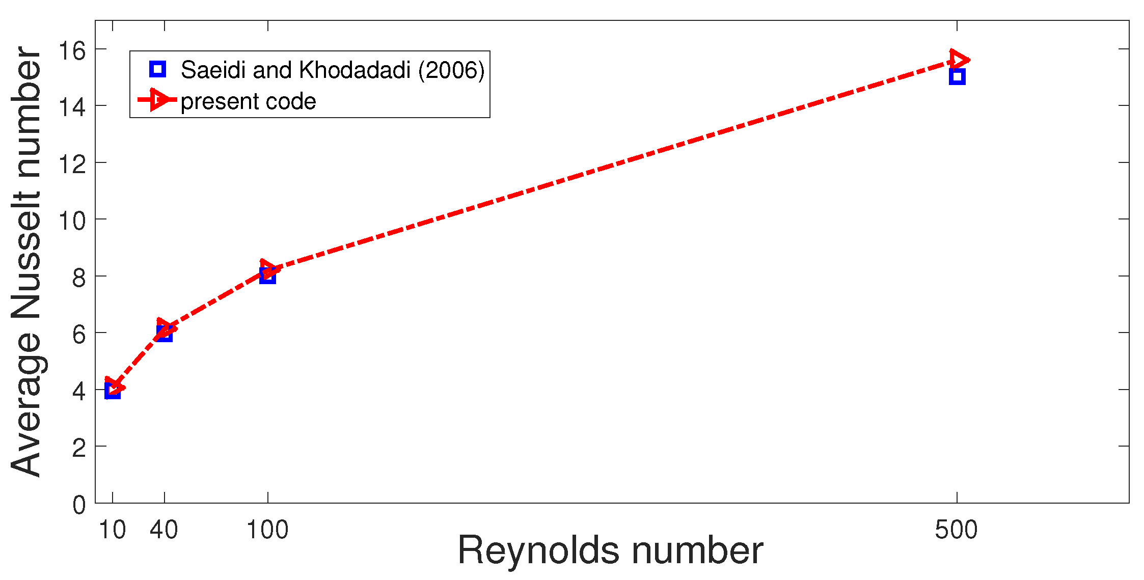
2.7. Grid Independence and Code Validation

Tests for grid independence of the solution are conducted. Figure 2a shows the test results for the generated power (PW with units in W) at two different Rew when using NF1 considering different grid sizes. A grid system gr-5 with a 3980431 number of elements is selected. The grid distribution of gr-5 system is shown in Figure 2b, and the grid is fine near the walls and at the interfaces.
Two different validation test cases are considered. In the first work, the numerical results of Khandelwal et al. [87] were used. In the study, the flow separation characteristics of a T channel were explored using shear thinning fluid. In Ref. [87], the authors developed a correlation for the dimensionless recirculation length with respect to changes in the Reynolds number and power-law index, and an exponential form of the correlation was used.
Figure 3 shows the comparison results of the normalized reattachment length for different power law indices at Re = 100. The maximum difference between the results was obtained as 5 % for n = 0.2. The second validation test case was performed for the convective HT in a cavity with ventilation ports, while the results of Saeidi and Khodadadi [1] were used. The configuration corresponds to case where the outlet port is located at the middle of the bottom wall, and the port size is taken as W = 0.25 (non-dimensionalized using the cavity height).
Figure 4 shows the variation of average Nu versus Re comparisons. The overall agreement between the results is adequate, and the highest deviation below 3% is obtained.

3. Results and Discussion

Performance optimization a TEG device using shear thinning nanofluid and a rotating cylinder in a vented cavity is performed. A rotating circular cylinder is located in the vented cavity, and a rotational Re number (Rew) is considered between −3000 and 3000. Two different fluids (shear thinning nanofluids-NF1 and NF2) are considered, and the solid volume faction and power law index of NF1 are (0.005, 0.88) and (0.045, 0.5) for NF2.
The size of the rotating object (R) is taken between 0.06 and 0.18 Hm, while locations of the object (Yp, Zp) are considered between (0.35, 0.35) and (0.65, 0.65). First, parametric CFD is used to see the trends in power characteristics of TEG with varying parameters. Then, the optimization algorithm is invoked to find the best location and size of the rotating object to deliver the highest power. The cases are also compared with a no-object configuration.
Figure 5 shows the impacts of the rotational Re number (Rew) on the flow pattern variations in the mid-plane of the 3D cavity when NF1 Figure 5a–c and NF2 Figure 5d–f are used. In the case of stationary object with NF1, a vortex is seen in the left upper part of the cylinder. When rotations are activated, at Rew = −3000 (CCW rotations), the upper vortex moves toward the right, while vortices appear near the lower part of the cylinder.
For CW rotation at Rew = 3000, the fluid is accelerated near the cylinder, and the vortices established in the previous cases disappeared. When NF2 is used, at Rew = 0, the main flow stream is directed toward the exit of the second port on the right. In this case, the fluid velocity is lower at the same Re value for NF2 and the cylinder acts as a barrier for the second flow stream to the first exit on the left. For CW directional rotation with NF2, the fluid stream from the inlet is directed toward the first and second exit ports under the cylinder with rotations since the fluid velocity is lower.
The variations in the FP distributions near the TEG device with cylinder rotations have influences on the variations of interface temperatures (ITs) in the x and y directions as shown in Figure 6. Compared to the motionless object case (Rew = 0), the temperature is higher in both directions at Rew = 3000 when the cylinder is rotating in the CCW direction. In this case, the hot fluid stream has more contact with the interface of the TEG, and the fluid velocity is higher. However, significant reductions in the IT are seen when the cylinder is rotating in the CW direction at the highest speed. This is due to the counter effects of rotation on the fluid stream movement toward the interface.
Generated power features versus the rotational Re number for different sizes and different shear thinning nanofluids are shown in Figure 7. As compared to the case with a cylinder size of R = 0.06 Hm, the configuration with a size of R = 0.18 Hm is significant regarding the power generation features when using NF1 and NF2. When NF1 is used, the generated power rises with higher values of Rew in the CCW direction (positive Rew), and the trend is the opposite for negative values of Rew. There is a 49% increase in the TEG power when the cases of lowest and highest rotational Re numbers are compared for NF1.
The amount of power reduction is obtained as 30% when a case for CW rotation at the highest speed is compared with the motionless cylinder configuration. A cylinder with a smaller size of R = 0.06 Hm has slight impacts of the power generation. The power characteristics are different with varying rotational velocity when NF2 is considered. In this case, since the fluid velocity is lower when rotations are activated, the impacts of rotation on the fluid stream movement toward the interface become important. Depending upon the rotational direction, the fluid stream goes from the bottom and top part of the cylinder to the exit and is spread over the TEG interface, which results in enhanced powers.
Even though the generated powers are lower in the case of NF1, the rise in the power becomes 76.3% and 103.2% when the motionless cylinder case is compared with activated rotation cases at Rew = −3000 and Rew = 3000 with using NF2. A comparison between the power features using NF1 and NF2 with varying Rew is considered in Figure 7c. The power is higher when using NF1 due to the increased fluid stream velocity and enhanced thermal transport.
The discrepancy between the generated powers of different nanofluids becomes the highest when the cylinder is not rotating, which is obtained as 68.5%. It is the lowest for CW rotation at Rew = −3000, which is calculated as 19%. This is attributed to the lower powers for NF1 and higher power features with NF2 with negative values of Rew. For CCW rotation at Rew = 3000, the amount of variation becomes 39%.
The locations of the object on the FP distribution in the mid-axis are shown in Figure 8 for NF1 at Rew = −3000 Figure 8a–c, for NF1 at Rew = 0 Figure 8d–f, for NF2 at Rew = −3000 Figure 8g–i and for NF2 at Rew = 0 Figure 8j–l. The position of the cylinder within the cavity is highly influential on the flow pattern variations. When rotations are not active for NF1, the vortex is formed on the upper part of the cylinder at (0.35, 0.35), while the fluid stream toward the left exit port is largely blocked at the location of (0.65, 0.65). When CCW rotations are activated for NF1, vortex formation appears near the right and upper part of the cylinder for the locations (0.35, 0.35) and (0.5, 0.5).
The fluid velocity is lower for NF2, while the partition of the main fluid stream for NF2 is apparent with the rotation of the cylinder. Figure 9 shows the generated power characteristics with different locations of the cylinder and rotational speeds for NF1 and NF2. When NF1 is considered, the highest powers are achieved at the locations (0.35, 0.35), (0.5, 0.5) and (0.5, 0.65) for rotational Re numbers of −3000, 0 and 3000, respectively.
However, the variations in the generated power with varying locations of the cylinder become 44.3%, 41.6% and 19% for these rotational speeds. When NF2 is used, the characteristics become different when compared to using NF1. The highest power is achieved at locations (0.65, 0.65) and (0.5, 0.65) for Rew = −3000 and Rew = 3000. Up to 61% variation in the generated power is obtained with a varying cylinder location when NF2 is utilized.
As seen, the generated power features with varying parameters of interest show non-monotonic behavior, and obtaining the best configuration in terms of higher power generation cannot be realized with parametric CFD. Therefore, optimization is needed to find the best location, size and rotational speed combination in order to have the maximum power from the device. Optimization studies are performed for configurations where NF 1and NF2 are used as the HT fluid.
Figure 10 shows the search for the maximum of the power with varying parameters obtained by utilizing the COBYLA algorithm. The optimum cases are obtained as (Rew, R, Yp, Zp) = (3000, 0.3 Hm, 0.479, 0.65) and (Rew, R, Yp, Zp) = (3000, 0.3 Hm, 0.49, 0.65) for NF1 and NF2, and the generated powers at those cases are calculated as 0.3328 and 0.2488. Figure 11 shows the comparison results of the flow pattern distributions between the optimum case and no-object case when NF1 and NF2 are used. The presence of the cylinder in the cavity at the optimum case affects the flow pattern variations in the cavity and near the TEG device when compared to the no-object case.
A vortex near the left corner is established for the case without a cylinder with NF2, and the rotations of the cylinder become effective in distributing the hot fluid stream over the TEG interface at the optimum. The flow features show similar trends except for the location of the rotating cylinder when NF1 is used. However, the acceleration of the fluid stream toward the interface with rotation is apparent for NF1. Figure 12 shows the variations of the IT between the optimum and no-object case in the y and z directions.
The trends in the curves are similar. The optimum case delivers higher temperatures, and the power generation will be higher. The amounts of the power increase at the optimum when compared to the no-object configuration become 11.5% and 161% for the NF1 and NF2 cases. Particularly for NF2, the amount of increment is substantial, while the flow directional movement is best accomplished using the rotating cylinder at the optimum configuration.
The advantage of using optimization for obtaining the best TEG performance is also compared with the parametric CFD simulation results. Figure 13 shows the comparison results for the enhancement (Enh) of the generated power in percentage when the no-object case is considered when NF1 and NF2 are used. For NF1, by installing a cylinder with CCW rotation (positive Rew), enhancements up to 4.5% are achieved with parametric CFD at the highest speed. However, when optimum solutions are used, the value is 6.5% higher with the parametric CFD value at this speed, which gives a 10.9% rise of the power with installed CFD when compared to the no-cylinder configuration.
In the case of CW rotation (negative values of Rew), installation of the cylinder is not advantageous, and the generated power reduces by about 46.6% at Rew = −3000 when the no-object case is compared. When the optimum case is considered using NF1, the power rises by about 11.5% when compared to the no-object case. Both CW and CCW rotations of the cylinder produce higher power outputs when NF2 is used. However, the optimum conditions produce more TEG power when compared to the parametric CFD, which are 41% and 18.5% at Rew = −3000 and Rew = 3000. Figure 14 shows the power generation enhancements with various locations of the cylinder in the parametric CFD configuration when compared to optimum cases using NF1 and NF2. The enhancements are significant especially when using the second nanofluid NF2 when the locations are varied at Rew = 0.
When NF1 is used, the impacts of the location at Yp = 0.65 seem to be significant at Re = 0 and Rew = 3000. These results show that significant variations in the generated power are obtained when the parametric CFD are compared with the optimum case, while using a rotating object in the ventilated cavity becomes advantageous when optimization algorithms are used along with the CFD simulations. Considering the computational cost of the fully coupled system of a 3D vented cavity with TEG, the importance of using optimization becomes apparent.

4. Conclusions

CFD simulation and optimization for the performance improvement of a TEG-installed cavity with multiple ports were conduced using an inner rotating cylinder and shear thinning nanofluid. The following conclusions were obtained:
  • For higher values of Rew, more power was generated when NF1 was used, while 49% enhancement in the power was obtained when cases with the lowest and highest Rew were compared.
  • The power generation features with varying Rew were different when using NF2. In this case, the power increased by about 76.3% and 103.2% at Rew = −3000 and Rew = 3000 in comparison to the motionless cylinder case at Rew = 0.
  • The generated power difference of nanofluids NF1 and NF2 was the maximum at Rew = 0, which was calculated as 68.5%.
  • The power characteristics behaved differently when NF1 and NF2 were compared. When the location of the cylinder was changed, up to 61% variation in the power generation was obtained.
  • The optimum configurations were achieved as (Rew, R, Yp, Zp) = (3000, 0.3 Hm, 0.479, 0.65) for NF1 and (Rew, R, Yp, Zp) = (3000, 0.3 Hm, 0.49, 0.65) for NF2.
  • When the optimum case was considered, the generated power was 11.5% higher for NF1 and 161% higher for NF2 in the no-object case.
  • Profound variations in the output power were observed when the optimum configuration was compared with parametric CFD. By using the optimization, installing a rotating object in the vented cavity became advantageous for the power increase of the TEG-installed system when both shear thinning nanofluids were used.
  • The computational cost of the high-fidelity coupled system was significantly reduced when optimization was used instead of parametric CFD.

Author Contributions

Conceptualization, F.S.; methodology, F.S., L.K. and N.B.K.; software, F.S.; validation, L.K.; formal analysis, F.S., N.B.K. and L.K; investigation, F.S., L.K., W.A., L.B.S. and I.B.; writing—original draft preparation, F.S.; writing—review and editing, F.S., L.K, W.A., L.B.S. and I.B.; visualization, F.S. and L.K.; supervision, F.S., L.B.S., L.K., I.B. and W.A. All authors have read and agreed to the published version of the manuscript.

Funding

This research has been funded by Scientific Research Deanship at University of Ha’il—Saudi Arabia through project number RG-20 084.

Institutional Review Board Statement

Not applicable.

Informed Consent Statement

Not applicable.

Data Availability Statement

Not applicable.

Conflicts of Interest

The authors declare no conflict of interest.

Abbreviations

dport size
hheat transfer coefficient
Hmcavity height
Jcurrent density
kthermal conductivity
Lmcavity length
npower law index
NuNusselt number
ppressure
PrPrandtl number
qheat flux
Rcylinder size
ReReynolds number
Rewrotational Reynolds number
Ttemperature
u, v, wx-y-z velocity components
Velectric potential
x, y, zCartesian coordinates
Greek Characters
α thermal diffusivity
μ dynamic viscosity
ν kinematic viscosity
ρ density of the fluid
Ω rotational velocity
Π Peltier coefficient
Subscripts
ccold wall
hhot wall
maverage
nfnanofluid
Abbreviations
CWclockwise
CCWcounter-clockwise
FEMfinite element method
NFnanofluid
PDEpartial differential equation
TEGthermoelectric generator
VCvented cavity
ZTfigure of merit

References

  1. Saeidi, S.; Khodadadi, J. Forced convection in a square cavity with inlet and outlet ports. Int. J. Heat Mass Transf. 2006, 49, 1896–1906. [Google Scholar] [CrossRef]
  2. Shuja, S.; Yilbas, B.; Iqbal, M. Mixed convection in a square cavity due to heat generating rectangular body: Effect of cavity exit port locations. Int. J. Numer. Methods Heat Fluid Flow 2000, 10, 824–841. [Google Scholar] [CrossRef]
  3. Ismael, M.A.; Jasim, H.F. Role of the fluid-structure interaction in mixed convection in a vented cavity. Int. J. Mech. Sci. 2018, 135, 190–202. [Google Scholar] [CrossRef]
  4. Chamkha, A.J.; Hussain, S.H.; Abd-Amer, Q.R. Mixed convection heat transfer of air inside a square vented cavity with a heated horizontal square cylinder. Numer. Heat Transf. Part A Appl. 2011, 59, 58–79. [Google Scholar] [CrossRef]
  5. Radhakrishnan, T.; Verma, A.; Balaji, C.; Venkateshan, S. An experimental and numerical investigation of mixed convection from a heat generating element in a ventilated cavity. Exp. Therm. Fluid Sci. 2007, 32, 502–520. [Google Scholar] [CrossRef]
  6. Shih, Y.C.; Khodadadi, J.; Nien, S.W.; Zeng, Y.; Huang, X.L. Impact of an oscillating guide vane on the thermo-hydraulic fields in a square cavity with single inlet and outlet ports. Int. J. Heat Mass Transf. 2019, 128, 1184–1200. [Google Scholar] [CrossRef]
  7. Selimefendigil, F.; Öztop, H.F. Fluid-solid interaction of elastic-step type corrugation effects on the mixed convection of nanofluid in a vented cavity with magnetic field. Int. J. Mech. Sci. 2019, 152, 185–197. [Google Scholar] [CrossRef]
  8. Shirvan, K.M.; Öztop, H.F.; Al-Salem, K. Mixed magnetohydrodynamic convection in a Cu-water-nanofluid-filled ventilated square cavity using the Taguchi method: A numerical investigation and optimization. Eur. Phys. J. Plus 2017, 132, 204. [Google Scholar] [CrossRef]
  9. Benzema, M.; Benkahla, Y.K.; Labsi, N.; Ouyahia, S.E.; El Ganaoui, M. Second law analysis of MHD mixed convection heat transfer in a vented irregular cavity filled with Ag–MgO/water hybrid nanofluid. J. Therm. Anal. Calorim. 2019, 137, 1113–1132. [Google Scholar] [CrossRef]
  10. Saeidi, S.; Khodadadi, J. Transient flow and heat transfer leading to periodic state in a cavity with inlet and outlet ports due to incoming flow oscillation. Int. J. Heat Mass Transf. 2007, 50, 530–538. [Google Scholar] [CrossRef]
  11. Sourtiji, E.; Hosseinizadeh, S.; Gorji-Bandpy, M.; Ganji, D. Heat transfer enhancement of mixed convection in a square cavity with inlet and outlet ports due to oscillation of incoming flow. Int. Commun. Heat Mass Transf. 2011, 38, 806–814. [Google Scholar] [CrossRef]
  12. Chamkha, A.J.; Selimefendigil, F.; Oztop, H.F. Pulsating flow of CNT–water nanofluid mixed convection in a vented trapezoidal cavity with an inner conductive T-shaped object and magnetic field effects. Energies 2020, 13, 848. [Google Scholar] [CrossRef] [Green Version]
  13. Garmroodi, M.D.; Ahmadpour, A.; Talati, F. MHD mixed convection of nanofluids in the presence of multiple rotating cylinders in different configurations: A two-phase numerical study. Int. J. Mech. Sci. 2019, 150, 247–264. [Google Scholar] [CrossRef]
  14. Bozorg, M.V.; Siavashi, M. Two-phase mixed convection heat transfer and entropy generation analysis of a non-Newtonian nanofluid inside a cavity with internal rotating heater and cooler. Int. J. Mech. Sci. 2019, 151, 842–857. [Google Scholar] [CrossRef]
  15. Roslan, R.; Saleh, H.; Hashim, I. Effect of rotating cylinder on heat transfer in a square enclosure filled with nanofluids. Int. J. Heat Mass Transf. 2012, 55, 7247–7256. [Google Scholar] [CrossRef]
  16. Khanafer, K.; Aithal, S.M.; Vafai, K. Mixed convection heat transfer in a differentially heated cavity with two rotating cylinders. Int. J. Therm. Sci. 2019, 135, 117–132. [Google Scholar] [CrossRef]
  17. Misirlioglu, A. The effect of rotating cylinder on the heat transfer in a square cavity filled with porous medium. Int. J. Eng. Sci. 2006, 44, 1173–1187. [Google Scholar] [CrossRef]
  18. Chamkha, A.J.; Selimefendigil, F.; Ismael, M.A. Mixed convection in a partially layered porous cavity with an inner rotating cylinder. Numer. Heat Transf. Part A Appl. 2016, 69, 659–675. [Google Scholar] [CrossRef]
  19. Shih, Y.C.; Khodadadi, J.; Weng, K.H.; Ahmed, A. Periodic fluid flow and heat transfer in a square cavity due to an insulated or isothermal rotating cylinder. J. Heat Transf. 2009, 131, 111701. [Google Scholar] [CrossRef]
  20. Alsabery, A.I.; Ghalambaz, M.; Armaghani, T.; Chamkha, A.; Hashim, I.; Saffari Pour, M. Role of rotating cylinder toward mixed convection inside a wavy heated cavity via two-phase nanofluid concept. Nanomaterials 2020, 10, 1138. [Google Scholar] [CrossRef]
  21. Hassanzadeh, R.; Rahimi, R.; Khosravipour, A.; Mostafavi, S.; Pekel, H. Analysis of natural convection in a square cavity in the presence of a rotating cylinder with a specific number of roughness components. Int. Commun. Heat Mass Transf. 2020, 116, 104708. [Google Scholar] [CrossRef]
  22. Alsabery, A.; Sheremet, M.A.; Chamkha, A.; Hashim, I. Impact of nonhomogeneous nanofluid model on transient mixed convection in a double lid-driven wavy cavity involving solid circular cylinder. Int. J. Mech. Sci. 2019, 150, 637–655. [Google Scholar] [CrossRef]
  23. Kareem, A.K.; Gao, S. Mixed convection heat transfer of turbulent flow in a three-dimensional lid-driven cavity with a rotating cylinder. Int. J. Heat Mass Transf. 2017, 112, 185–200. [Google Scholar] [CrossRef] [Green Version]
  24. Selimefendigil, F.; Öztop, H.F. Combined effects of double rotating cones and magnetic field on the mixed convection of nanofluid in a porous 3D U-bend. Int. Commun. Heat Mass Transf. 2020, 116, 104703. [Google Scholar] [CrossRef]
  25. Kareem, A.K.; Gao, S. A comparison study of mixed convection heat transfer of turbulent nanofluid flow in a three-dimensional lid-driven enclosure with a clockwise versus an anticlockwise rotating cylinder. Int. Commun. Heat Mass Transf. 2018, 90, 44–55. [Google Scholar] [CrossRef] [Green Version]
  26. Selimefendigil, F.; Öztop, H.F. Conjugate mixed convection of nanofluid in a cubic enclosure separated with a conductive plate and having an inner rotating cylinder. Int. J. Heat Mass Transf. 2019, 139, 1000–1017. [Google Scholar] [CrossRef]
  27. Khanafer, K.; Vafai, K. A review on the applications of nanofluids in solar energy field. Renew. Energy 2018, 123, 398–406. [Google Scholar] [CrossRef]
  28. Pordanjani, A.H.; Aghakhani, S.; Afrand, M.; Mahmoudi, B.; Mahian, O.; Wongwises, S. An updated review on application of nanofluids in heat exchangers for saving energy. Energy Convers. Manag. 2019, 198, 111886. [Google Scholar] [CrossRef]
  29. Borode, A.; Ahmed, N.; Olubambi, P. A review of solar collectors using carbon-based nanofluids. J. Clean. Prod. 2019, 241, 118311. [Google Scholar] [CrossRef]
  30. Sajid, M.U.; Ali, H.M. Recent advances in application of nanofluids in heat transfer devices: A critical review. Renew. Sustain. Energy Rev. 2019, 103, 556–592. [Google Scholar] [CrossRef]
  31. Taherian, H.; Alvarado, J.L.; Languri, E.M. Enhanced thermophysical properties of multiwalled carbon nanotubes based nanofluids. Part 1: Critical review. Renew. Sustain. Energy Rev. 2018, 82, 4326–4336. [Google Scholar] [CrossRef]
  32. Özerinç, S.; Kakaç, S.; Yazıcıoğlu, A.G. Enhanced thermal conductivity of nanofluids: A state-of-the-art review. Microfluid. Nanofluid. 2010, 8, 145–170. [Google Scholar] [CrossRef]
  33. Pordanjani, A.H.; Aghakhani, S.; Afrand, M.; Sharifpur, M.; Meyer, J.P.; Xu, H.; Ali, H.M.; Karimi, N.; Cheraghian, G. Nanofluids: Physical phenomena, applications in thermal systems and the environment effects-a critical review. J. Clean. Prod. 2021, 320, 128573. [Google Scholar] [CrossRef]
  34. Zahmatkesh, I.; Sheremet, M.; Yang, L.; Heris, S.Z.; Sharifpur, M.; Meyer, J.P.; Ghalambaz, M.; Wongwises, S.; Jing, D.; Mahian, O. Effect of nanoparticle shape on the performance of thermal systems utilizing nanofluids: A critical review. J. Mol. Liq. 2021, 321, 114430. [Google Scholar] [CrossRef]
  35. Mahian, O.; Bellos, E.; Markides, C.N.; Taylor, R.A.; Alagumalai, A.; Yang, L.; Qin, C.; Lee, B.J.; Ahmadi, G.; Safaei, M.R.; et al. Recent advances in using nanofluids in renewable energy systems and the environmental implications of their uptake. Nano Energy 2021, 86, 106069. [Google Scholar] [CrossRef]
  36. Ali, F.H.; Hamzah, H.K.; Egab, K.; Arıcı, M.; Shahsavar, A. Non-Newtonian nanofluid natural convection in a U-shaped cavity under magnetic field. Int. J. Mech. Sci. 2020, 186, 105887. [Google Scholar] [CrossRef]
  37. Kefayati, G.R. Simulation of heat transfer and entropy generation of MHD natural convection of non-Newtonian nanofluid in an enclosure. Int. J. Heat Mass Transf. 2016, 92, 1066–1089. [Google Scholar] [CrossRef]
  38. Ellahi, R.; Sait, S.M.; Shehzad, N.; Mobin, N. Numerical simulation and mathematical modeling of electro-osmotic Couette–Poiseuille flow of MHD power-law nanofluid with entropy generation. Symmetry 2019, 11, 1038. [Google Scholar] [CrossRef] [Green Version]
  39. Kefayati, G.R. FDLBM simulation of magnetic field effect on mixed convection in a two sided lid-driven cavity filled with non-Newtonian nanofluid. Powder Technol. 2015, 280, 135–153. [Google Scholar] [CrossRef]
  40. Ellahi, R. The effects of MHD and temperature dependent viscosity on the flow of non-Newtonian nanofluid in a pipe: Analytical solutions. Appl. Math. Model. 2013, 37, 1451–1467. [Google Scholar] [CrossRef]
  41. Shamsi, M.R.; Akbari, O.A.; Marzban, A.; Toghraie, D.; Mashayekhi, R. Increasing heat transfer of non-Newtonian nanofluid in rectangular microchannel with triangular ribs. Phys. E Low-Dimens. Syst. Nanostruct. 2017, 93, 167–178. [Google Scholar] [CrossRef]
  42. Raizah, Z.; Aly, A.M.; Ahmed, S.E. Natural convection flow of a power-law non-Newtonian nanofluid in inclined open shallow cavities filled with porous media. Int. J. Mech. Sci. 2018, 140, 376–393. [Google Scholar] [CrossRef]
  43. Siavashi, M.; Rostami, A. Two-phase simulation of non-Newtonian nanofluid natural convection in a circular annulus partially or completely filled with porous media. Int. J. Mech. Sci. 2017, 133, 689–703. [Google Scholar] [CrossRef]
  44. Champier, D. Thermoelectric generators: A review of applications. Energy Convers. Manag. 2017, 140, 167–181. [Google Scholar] [CrossRef]
  45. Zhou, S.; Sammakia, B.; White, B.; Borgesen, P.; Chen, C. Multiscale modeling of thermoelectric generators for the optimized conversion performance. Int. J. Heat Mass Transf. 2013, 10, 435–444. [Google Scholar] [CrossRef]
  46. Patil, D.S.; Arakerimath, R.R.; Walke, P.V. Thermoelectric materials and heat exchangers for power generation—A review. Renew. Sustain. Energy Rev. 2018, 95, 1–22. [Google Scholar] [CrossRef]
  47. Karthick, K.; Suresh, S.; Hussain, M.M.M.D.; Ali, H.M.; Kumar, C.S.S. Evaluation of solar thermal system configurations for thermoelectric generator applications: A critical review. Sol. Energy 2019, 188, 111–142. [Google Scholar] [CrossRef]
  48. Rajaee, F.; Rad, M.A.V.; Kasaeian, A.; Mahian, O.; Yan, W.M. Experimental analysis of a photovoltaic/thermoelectric generator using cobalt oxide nanofluid and phase change material heat sink. Energy Convers. Manag. 2020, 21215, 112780. [Google Scholar] [CrossRef]
  49. Nazari, S.; Safarzadeh, H.; Bahiraei, M. Experimental and analytical investigations of productivity, energy and exergy efficiency of a single slope solar still enhanced with thermoelectric channel and nanofluid. Renew. Energy 2019, 135, 729–744. [Google Scholar] [CrossRef]
  50. Rowe, D.M. Recent developments in thermoelectric materials. Appl. Energy 1986, 24, 139–162. [Google Scholar] [CrossRef]
  51. Gelbstein, Y. Pb1−xSnxTe alloys: Application considerations. J. Electron. Mater. 2011, 40, 533–536. [Google Scholar] [CrossRef]
  52. He, W.; Zhang, G.; Zhang, X.; Ji, J.; Zhao, X. Recent development and application of thermoelectric generator and cooler. Appl. Energy 2015, 143, 1–25. [Google Scholar] [CrossRef]
  53. Gelbstein, Y.; Davidow, J.; Leshem, E.; Pinshow, O.; Moisa, S. Significant lattice thermal conductivity reduction following phase separation of the highly efficient GexPb1−xTe thermoelectric alloys. Phys. Status Solidi B 2014, 251, 1431–1437. [Google Scholar] [CrossRef]
  54. Selimefendigil, F.; Öztop, H.F. Performance of TEG integrated channel with area expansion by using advanced passive techniques. Int. J. Mech. Sci. 2021, 194, 106210. [Google Scholar] [CrossRef]
  55. Nnanna, A.G.A.; Rutherford, W.; Elomar, W.; Sankowski, B. Assessment of thermoelectric module with nanofluid heat exchanger. Appl. Therm. Eng. 2009, 29, 491–500. [Google Scholar] [CrossRef]
  56. Ahammed, N.; Asirvatham, L.G.; Wongwises, S. Entropy generation analysis of graphene-alumina hybrid nanofluid in multiport minichannel heat exchanger coupled with thermoelectric cooler. Int. J. Heat Mass Transf. 2016, 103, 1084–1097. [Google Scholar] [CrossRef]
  57. Ahammed, N.; Asirvatham, L.G.; Wongwises, S. Thermoelectric cooling of electronic devices with nanofluid in a multiport minichannel heat exchanger. Exp. Therm. Fluid Sci. 2016, 74, 81–90. [Google Scholar] [CrossRef]
  58. Selimefendigil, F.; Öztop, H.F. Identification of pulsating flow effects with CNT nanoparticles on the performance enhancements of thermoelectric generator (TEG) module in renewable energy applications. Renew. Energy 2020, 162, 1076–1086. [Google Scholar] [CrossRef]
  59. Kalogirou, S.A. Applications of artificial neural-networks for energy systems. Appl. Energy 2000, 67, 17–35. [Google Scholar] [CrossRef]
  60. Koca, A.; Oztop, H.F.; Varol, Y.; Koca, G.O. Estimation of solar radiation using artificial neural networks with different input parameters for Mediterranean region of Anatolia in Turkey. Expert Syst. Appl. 2011, 38, 8756–8762. [Google Scholar] [CrossRef]
  61. Kalogirou, S.A. Artificial neural networks in renewable energy systems applications: A review. Renew. Sustain. Energy Rev. 2001, 5, 373–401. [Google Scholar] [CrossRef]
  62. Amirkhani, S.; Nasirivatan, S.; Kasaeian, A.; Hajinezhad, A. ANN and ANFIS models to predict the performance of solar chimney power plants. Renew. Energy 2015, 83, 597–607. [Google Scholar] [CrossRef]
  63. Suganthi, L.; Iniyan, S.; Samuel, A.A. Applications of fuzzy logic in renewable energy systems—A review. Renew. Sustain. Energy Rev. 2015, 48, 585–607. [Google Scholar] [CrossRef]
  64. Entchev, E. Residential fuel cell energy systems performance optimization using “soft computing” techniques. J. Power Sources 2003, 118, 212–217. [Google Scholar] [CrossRef]
  65. Gopalakrishnan, K.; Khaitan, S.K.; Kalogirou, S. Soft Computing in Green and Renewable Energy Systems; Springer: New York, NY, USA, 2011; Volume 269. [Google Scholar]
  66. Selimefendigil, F.; Coban, S.O.; Öztop, H.F. An efficient method for optimizing the unsteady heat and mass transport features for convective drying of two porous moist objects in a channel. Int. J. Mech. Sci. 2021, 200, 106444. [Google Scholar] [CrossRef]
  67. Zhu, Y.; Newbrook, D.W.; Dai, P.; de Groot, C.K.; Huang, R. Artificial neural network enabled accurate geometrical design and optimisation of thermoelectric generator. Appl. Energy 2022, 305, 117800. [Google Scholar] [CrossRef]
  68. Selimefendigil, F.; Öztop, H.F.; Kolsi, L.; Omri, M. Performance analysis of thermoelectric generator mounted chaotic channel by using non-Newtonian nanofluid and modeling with efficient computational methods. Alex. Eng. J. 2022, 61, 3527–3549. [Google Scholar] [CrossRef]
  69. Garud, K.S.; Seo, J.H.; Cho, C.P.; Lee, M.Y. Artificial neural network and adaptive neuro-fuzzy interface system modelling to predict thermal performances of thermoelectric generator for waste heat recovery. Symmetry 2020, 12, 259. [Google Scholar] [CrossRef] [Green Version]
  70. Bahiraei, M.; Nazari, S.; Moayedi, H.; Safarzadeh, H. Using neural network optimized by imperialist competition method and genetic algorithm to predict water productivity of a nanofluid-based solar still equipped with thermoelectric modules. Powder Technol. 2020, 366, 571–586. [Google Scholar] [CrossRef]
  71. Angeline, A.A.; Asirvatham, L.G.; Hemanth, D.J.; Jayakumar, J.; Wongwises, S. Performance prediction of hybrid thermoelectric generator with high accuracy using artificial neural networks. Sustain. Energy Technol. Assess. 2019, 33, 53–60. [Google Scholar] [CrossRef]
  72. Bahiraei, M.; Nazari, S.; Safarzadeh, H. Modeling of energy efficiency for a solar still fitted with thermoelectric modules by ANFIS and PSO-enhanced neural network: A nanofluid application. Powder Technol. 2021, 385, 185–198. [Google Scholar] [CrossRef]
  73. Selimefendigil, F.; Öztop, H.F. Thermoelectric generation in bifurcating channels and efficient modeling by using hybrid CFD and artificial neural networks. Renew. Energy 2021, 172, 582–598. [Google Scholar] [CrossRef]
  74. Putra, N.; Roetzel, W.; Das, S.K. Natural convection of nano-fluids. Heat Mass Transf. 2003, 39, 775–784. [Google Scholar] [CrossRef]
  75. Chon, C.H.; Kihm, K.D.; Lee, S.P.; Choi, S.U. Empirical correlation finding the role of temperature and particle size for nanofluid (Al2O3) thermal conductivity enhancement. Appl. Phys. Lett. 2005, 87, 153107. [Google Scholar] [CrossRef]
  76. Kim, C.N. Development of a numerical method for the performance analysis of thermoelectric generators with thermal and electric contact resistance. Appl. Therm. Eng. 2018, 1305, 408–417. [Google Scholar] [CrossRef]
  77. Powell, M.J. A direct search optimization method that models the objective and constraint functions by linear interpolation. In Advances in Optimization and Numerical Analysis; Springer: Dordrecht, The Netherlands, 1994; pp. 51–67. [Google Scholar]
  78. e Silva, S.R.; Gomes, R.; Falcao, A. Hydrodynamic optimization of the UGEN: Wave energy converter with U-shaped interior oscillating water column. Int. J. Mar. Energy 2016, 15, 112–126. [Google Scholar] [CrossRef]
  79. Lewis, R.W.; Nithiarasu, P.; Seetharamu, K.N. Fundamentals of the Finite Element Method for Heat and Fluid Flow; John Wiley & Sons: West Sussex, UK, 2004. [Google Scholar]
  80. Nithiarasu, P.; Lewis, R.W.; Seetharamu, K.N. Fundamentals of the Finite Element Method for Heat and Mass Transfer; John Wiley & Sons: New York, NY, USA, 2016. [Google Scholar]
  81. Reddy, J.N.; Gartling, D.K. The Finite Element Method in Heat Transfer and Fluid Dynamics; CRC Press: Boca Raton, FL, USA, 2010. [Google Scholar]
  82. Heinrich, J.C.; Pepper, D.W. Intermediate Finite Element Method: Fluid Flow and Heat Transfer Applications; Routledge: New York, NY, USA, 2017. [Google Scholar]
  83. Jang, B.; Han, S.; Kim, J.Y. Optimal design for micro-thermoelectric generators using finite element analysis. Microelectron. Eng. 2011, 88, 775–778. [Google Scholar] [CrossRef]
  84. Pérez-Aparicio, J.L.; Taylor, R.; Gavela, D. Finite element analysis of nonlinear fully coupled thermoelectric materials. Comput. Mech. 2007, 40, 35–45. [Google Scholar] [CrossRef]
  85. Geppert, B.; Groeneveld, D.; Loboda, V.; Korotkov, A.; Feldhoff, A. Finite-element simulations of a thermoelectric generator and their experimental validation. Energy Harvest. Syst. 2015, 2, 95–104. [Google Scholar] [CrossRef]
  86. Selimefendigil, F.; Öztop, H.F. Thermoelectric generation from vented cavities with a rotating conic object and highly conductive CNT nanofluids for renewable energy systems. Int. Commun. Heat Mass Transf. 2021, 122, 105139. [Google Scholar] [CrossRef]
  87. Khandelwal, V.; Dhiman, A.; Baranyi, L. Laminar flow of non-Newtonian shear-thinning fluids in a T-channel. Comput. Fluids 2015, 108, 79–91. [Google Scholar] [CrossRef]
Figure 1. TEG-installed VC using a rotating cylinder and shear thinning nanofluid in 3D (a) and 2D view with dimensions (b).
Mathematics 10 01075 g001
Figure 2. The grid independence test results for the generated power (PW with units in W) at two different Rew for NF1 (a) and grid distribution in the domain (b).
Mathematics 10 01075 g002
Figure 3. Validation test case 1: Normalized reattachment length versus power law index comparisons between the work of [87] at Re = 100. In the study, the shear thinning fluid flow behavior in a T-channel was analyzed.
Mathematics 10 01075 g003
Figure 4. Validation test case 2: Average Nu versus Re comparisons using the available results of [1]. In the work, the convection characteristics in a ventilated cavity were explored.
Mathematics 10 01075 g004
Figure 5. FP distributions in the VC with varying Rew for both nanofluids (R = 0.18 Hm, (Yp, Zp) = (0.5, 0.5)). (a) Rew = −3000, NF1, (b) Rew = 0, NF1, (c) Rew = 3000, NF1, (d) Rew = −3000, NF2, (e) Rew = 0, NF2, (f) Rew = 3000, NF2.
Mathematics 10 01075 g005
Figure 6. Variation of the IT in the x (a) and y (b) directions at several Rew values using NF1 (R = 0.18 Hm, (Yp, Zp) = (0.5, 0.5)).
Mathematics 10 01075 g006
Figure 7. Generated power versus Rew for NF1 (a) and NF2 (b) with two different sizes ((Yp, Zp) = (0.5, 0.5)). The impacts of nanofluid type on the power generation versus Re (c) for (R = 0.18 Hm, (Yp, Zp) = (0.5, 0.5)).
Mathematics 10 01075 g007
Figure 8. Impacts of location of the rotating cylinder on the FP distribution in the VC for NF1 (af) and for NF2 (gl) (R = 0.18 Hm, Rew = −3000 (ac,gi) and Rew = 0 (df,jl)). (a) (Yp, Zp) = (0.35, 0.35). (b) (Yp, Zp) = (0.5, 0.5). (c) (Yp, Zp) = (0.65, 0.65). (d) (Yp, Zp) = (0.35, 0.35). (e) (Yp, Zp) = (0.5, 0.5). (f) (Yp, Zp) = (0.65, 0.65). (g) (Yp, Zp) = (0.35, 0.35). (h) (Yp, Zp) = (0.5, 0.5). (i) (Yp, Zp) = (0.65, 0.65). (j) (Yp, Zp) = (0.35, 0.35). (k) (Yp, Zp) = (0.5, 0.5). (l) (Yp, Zp) = (0.65, 0.65).
Mathematics 10 01075 g008
Figure 9. Effects of the rotating cylinder location on the variation of generated power for NF1 (ac) and for NF2 (d,e) for various Rew values (R = 0.18 Hm).
Mathematics 10 01075 g009
Figure 10. Search for the optimum set of parameters for the maximum power generation considering varying size-rotation (a), location-rotation (b) and location-size (c).
Mathematics 10 01075 g010
Figure 11. FP variations in the 2D mid-plane of the VC for the case of no-object (a,b) and the optimum conditions (c,d) using NF1 and NF2.
Mathematics 10 01075 g011
Figure 12. Comparison of the IT distributions in the x (a) and y (b) directions. Power generation (c) in the case of the optimum configuration and in the case of no-object.
Mathematics 10 01075 g012
Figure 13. Enhancement in the generated power versus Rew when the optimum-parametric CFD and no object-parametric CFD cases are compared for NF1 (a) and for NF2 (b).
Mathematics 10 01075 g013
Figure 14. Impacts of the rotating cylinder location in the VC on the enhancement of the generated power when optimum-parametric CFD cases are compared for NF1 and for NF2 at various Rew values. (a) NF1, Rew = −3000, (b) NF3, Rew = −3000, (c) NF1, Rew = 0, (d) NF3, Rew = 0, (e) NF1, Rew = 3000, (f) NF3, Rew = 3000.
Mathematics 10 01075 g014
Publisher’s Note: MDPI stays neutral with regard to jurisdictional claims in published maps and institutional affiliations.

