Article

Modeling and Fatigue Characteristic Analysis of the Gear Flexspline of a Harmonic Reducer

1
School of Mechanical Engineering and Automation, Northeastern University, Shenyang 110819, China
2
School of Mechanical Engineering, Ningxia Institute of Science and Technology, Shizuishan 753000, China
*
Author to whom correspondence should be addressed.
Mathematics 2022, 10(6), 868; https://doi.org/10.3390/math10060868
Submission received: 19 January 2022 / Revised: 26 February 2022 / Accepted: 4 March 2022 / Published: 9 March 2022

Abstract

:
The failure of harmonic gear drive is mainly caused by the fatigue fracture of flexible wheels and the fatigue damage of flexible bearings. In this paper, the stress sensitivity and fatigue life characteristics of flexible wheels with thin-walled vulnerable components are studied. Firstly, the structure of the flexible wheel of a B3-80 general harmonic gear reducer is designed, the finite element model of the flexible wheel is established by using ANSYS finite element software, and the finite element analysis results are compared with the theoretical calculations to verify the correctness of the model. Finally, by changing the cylinder length, smooth cylinder wall thickness and load, the maximum equivalent stress curves of the flexible gear ring, smooth cylinder and flexible wheel bottom are obtained, and the influence law of structural parameters on the stress characteristics of flexible wheel is obtained. At the same time, the influence laws of flexible wheel cylinder length and smooth cylinder wall thickness on the fatigue life of flexible wheel is studied, which provides a theoretical basis for the structural optimization design of the cup flexible wheel.

1. Introduction

Harmonic gear drive is widely used in industrial robots, aerospace and optics and other fields, and has the ability to work normally in vacuum, strong radiation and large temperature difference environments. The failure of harmonic gear transmission is mainly caused by the fatigue fracture of the flexspline and the fatigue damage of flexible bearings [1]. Therefore, it is of great engineering significance to analyze the contact mechanical characteristics and study on fatigue life characteristics of the flexspline of thin-wall fragile components. Domestic and international scholars have conducted extensive research on gear tooth meshing, flexspline strength, mechanical characteristics and fatigue life in harmonic gear transmission. Jia et al. [2] studied the motion error of the harmonic drive, analyzed the beat frequency phenomenon caused by it, and carried out experimental verification with a harmonic reducer. Li et al. [3] took the wave generator of a harmonic drive as the research object. Based on the support function, the stress of spline is optimized by designing different contours, and its stress and deformation are studied by the finite element method. Dennis et al. [4] estimated the contact stress and bending stress of flexible gear teeth through the combination of nonlinear dynamic simulation and finite element analysis, and determined the influence of flexible gear tooth shape change on harmonic transmission performance. Li [5] carried out finite element simulation analysis on a cylindrical flexible wheel, cup flexible wheel and top hat flexible wheel; studied the stress characteristics of flexible wheels with different structures; and verified the simulation results with reference to experiments. Pacana et al. [6] established four wave generator models of double roller, four roller, CAM and disc. Under no-load and load conditions, they numerically calculated the stress value at the flexible gear teeth of harmonic drive and studied the influence of the type of wave generator on the stress distribution of flexible gear teeth. Oguz et al. [7] proposed a stress–strain analysis method based on the finite element method to calculate the stress of flexspline teeth and found the best tooth profile to maximize the service life of flexspline. Ostapski [8,9] analyzed the stress distribution of flexible bearings under symmetrical radial load and the influence of assembly error on fatigue damage of flexible bearings by the finite element method. In 1961, Sun Wei introduced harmonic gear drive technology into China, and he made outstanding contributions in the theoretical research and practical application of harmonic drive technology [10]. Leno et al. [11] determined the influence of the geometric structure change of flexible gear teeth on the performance of a double wave harmonic drive through statistical analysis to evaluate the motion error, load capacity, bending fatigue strength and pitting corrosion. Gravagno et al. [12] studied the influence of the shape of the wave generator on the motion error in the process of harmonic drive and quantitatively evaluated it. Zhang et al. [13] studied the materials of the flexible wheel and the changes of material properties in the manufacturing process, and analyzed the control strategy of austenite grain refinement and homogenization of the flexible wheel. In 2011, Xiao et al. [14] established the mathematical model of harmonic drive CAM wave generator and optimized the structure of CAM wave generator by using finite element software. Based on the theory of rigid-flexible coupling and transient dynamics analysis, Ye Nanhai et al. [15] obtained the stress distribution state and fatigue failure position of the flexspline during assembly and meshing, and then carried out fatigue life sensitivity analysis on the geometric structure and material parameters of the flexspline and established the fatigue life model of the flexspline.
According to the research on harmonic gear reducer geometric parameters on flexural stress sensitivity and fatigue life of the law of the study, harmonic drive is based on the thin wall shell elastic deformation theory on the basis of a new transmission mode, and harmonic gear reducer research is usually conducted with the help of finite element software. Generally, the model is simplified to a certain extent, such as the Flexspline being simplified as a smooth cylindrical shell, the wave generator being simplified as a CAM, or the approximate model being an axisymmetrical structure, which represents one-quarter of the analysis. Different degrees of simplification will inevitably affect the mechanical properties of the model. Therefore, this paper first designs the complete structure of the flexible wheel, and then establishes the finite element model of the flexible wheel according to its structural size. Finally, the effects of cylinder length and smooth cylinder wall thickness on the mechanical and fatigue characteristics of the flexspline are analyzed.

2. Structure Design and Model Establishment of a Harmonic Gear Reducer Flexible Wheel

According to [16], when the inner diameter of the flexspline is 80 mm, the nominal transmission ratio can be selected in five cases: 85, 100, 125, 160 and 200. Different transmission ratios correspond to different modulii and allowable torque of the low-speed shaft. The transmission ratio of the reducer is determined by the number of teeth of the flexspline and working conditions. Considering the size of the finite element model, simulation time and other factors, this paper selected the first case in the literature [16] for analysis. The inner diameter of the flexible wheel was 80 mm, the nominal transmission ratio of the flexible wheel was 85, the module 0.5 mm, the allowable torque of the low-speed shaft was 90 N·m, the allowable radial load of the low-speed shaft was 3000 N, and the weight was 9.2 kg.
Flexspline mainly adopts an involute tooth profile and double circular arc tooth profile [17,18]. An involute tooth profile has simple structure, convenient processing and manufacturing, and is widely used. This paper studied the involute tooth profile, and its equation can be described by Equation (1).
{ x = r b ( cos θ + θ sin θ ) y = r b ( sin θ θ cos θ )
where r b is the radius of the base circle and θ is the angle between the connecting line between the fixed point and the center of the circle and the x axis.
The flexspline teeth of a harmonic gear reducer mainly adopt an involute narrow cogging, and there are three types of pressure angles: 20°, 30° and 28°35″ [19]. Because the tooth profile with 20 pressure angle is easy to process and widely used, the pressure angle α = 20° is selected for the involute tooth. In order to prevent interference in the meshing process between the flexspline and rigid wheel, the modification coefficients of the flexspline and rigid wheel are designed as follows:
{ x f = [ ( D m z f ) / 2 + δ + ( h a * + c * ) m ] / m x g = x f + ( w * 1 )
where D is the outer diameter of flexible bearing, z f is the number of flexspline teeth, δ is the wall thickness of the flexspline ring gear, h a * is the coefficient of tooth crest height, c * is the coefficient of top clearance, m is the modulus, and w* is the coefficient of radial deformation. The crest height coefficient h a * = 1.0 is selected, and the crest clearance coefficient c * = 0.35 when the modulus m 1 . The radial deformation coefficient was generally in the range of w* = 0.8~1.2 and w* = 1.0 in this paper. According to [19], the value range of wall thickness coefficient of the flexspline is 0.01~0.0145. The wall thickness of the flexspline ring gear was obtained by the product of wall thickness coefficient and flexspline inner diameter, and δ = 1 was taken in this paper.
According to its different shapes and structures, flexspline can be divided into two forms [20]: a cylindrical cup shape and bell shape. In this paper, the flexspline was designed according to the cylindrical cup structure, and the coupling mode adopted a screw connection. The structure schematic of the flexspline is shown in Figure 1, and the main geometric structure parameters of the flexspline obtained by the calculations are presented in [20].
After completing the structural design, the finite element model of the flexible wheel is established according to the structural parameters. Because the structure of the flexible gear is complex and there are many teeth in its circumferential direction, if it is modeled with the help of other three-dimensional software, after importing the finite element software, the meshing near the ring gear will become very complex, with a long solution time and poor mesh quality, which will affect the accuracy of the calculation results. Therefore, this paper adopts the bottom-up method to directly establish the flexible wheel finite element model in ANSYS. The flexible wheel finite element model is shown in Figure 2.
This paper focuses on the contact mechanical characteristics between the wave generator and the flexible wheel. The chamfers R 1 , R 2 and R 3 , as shown in Figure 1, as well as the pin holes and smooth holes on the bottom flange of the flexspline are ignored in modeling. The flexible wheel was made of alloy structural steel 30CrMnSi, with an elastic modulus of 204 GPa, Poisson’s ratio of 0.29, density of 6691 kg/m3, and a yield limit of 885 MPa. When modeling, we first defined the four node plane182 element and eight node solid185 element, and completed the setting of 30CrMnSi material parameters, then generated the finite element model of a single tooth surface by using the mapping mesh division method; finally, we made the flexible wheel model corresponding to a single tooth by stretching the tooth surface, and converting the Cartesian coordinate system into the first kind of the cylindrical coordinate system. The complete finite element model of the flexible wheel was obtained by copying along the circumferential direction. As shown in Figure 2, the model contained 1,445,694 units and 1,840,442 nodes.

3. Verification of the Finite Element Model

3.1. Simplification of the Mesh Model of the Flexspline Tooth Profile

Because the meshing process of the gear teeth is not involved in the analysis of the influence law of the geometric structure parameters on the mechanical characteristics of flexible gear, it was necessary to re-divide the mesh of the tooth profile in the flexible gear finite element model to reduce the calculation scale.
The mesh division of the tooth profile of the flexible wheel finite element model is shown in Figure 3. The numbers of elements and nodes of the single-tooth plane model are, respectively, 361 and 409. On the basis of Figure 3, after the thinning the operation of removing elements at the edge of the tooth profile, the simplified tooth profile meshing was obtained and is shown in Figure 4. The numbers of elements and nodes of the single-tooth plane model are, respectively, 80 and 101. Then, the assembly simulation of the middle section of the flexible gear ring and the section of the cosine CAM wave generator was carried out to explore the deformation and force changes of the flexible gear before and after the simplification of the tooth profile mesh.
First, the contact wizard was used to set the contact pair, and the static friction coefficient was 0.02 and the normal contact stiffness coefficient was 0.05. Then, the zero-displacement constraint of Cam section in the y-axis direction was set to control the left and right half Cam sections to move 0.5 mm along the negative and positive directions of the x axis to simulate the assembly process of the flexspline and cosine cam. Finally, the augmented Lagrange algorithm was used to solve the problem, and the cross-section deformation nephogram and stress nephogram of flexspline ring gear before and after tooth profile mesh simplification are shown in Figure 5 and Figure 6, respectively.
It can be seen from Figure 5 and Figure 6 that the variation trend of the deformation nephogram and stress nephogram in the cross section of flexspline ring gear before and after tooth profile mesh simplification is consistent. In the deformation nephogram, the maximum deformation in x-axis direction and y-axis direction is 0.503 mm before and 0.501 mm after tooth profile mesh simplification, which is reduced by 2 µ m. In the stress nephogram, the stress value at the tooth root of the section is evidently greater than that in other areas, which shows that the stress concentration phenomenon occurs at the root of the tooth. The maximum equivalent stress of tooth profile mesh is 241 MPa before simplification and 245 MPa after simplification, which is increased by 4 MPa. On the whole, the simplification of the flexspline tooth profile mesh hardly affects its deformation and stress. Therefore, the following analysis of the flexspline in this section is carried out on the basis of simplifying the tooth profile grid.

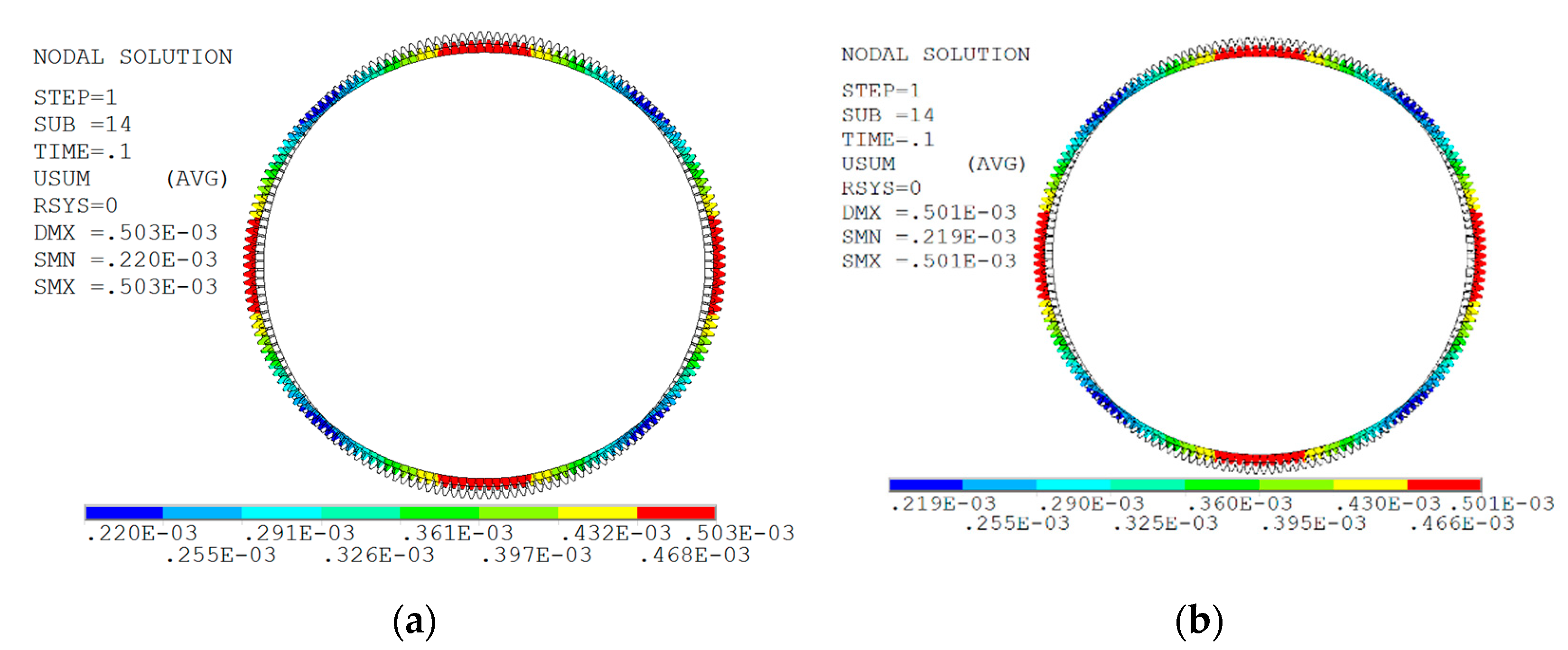
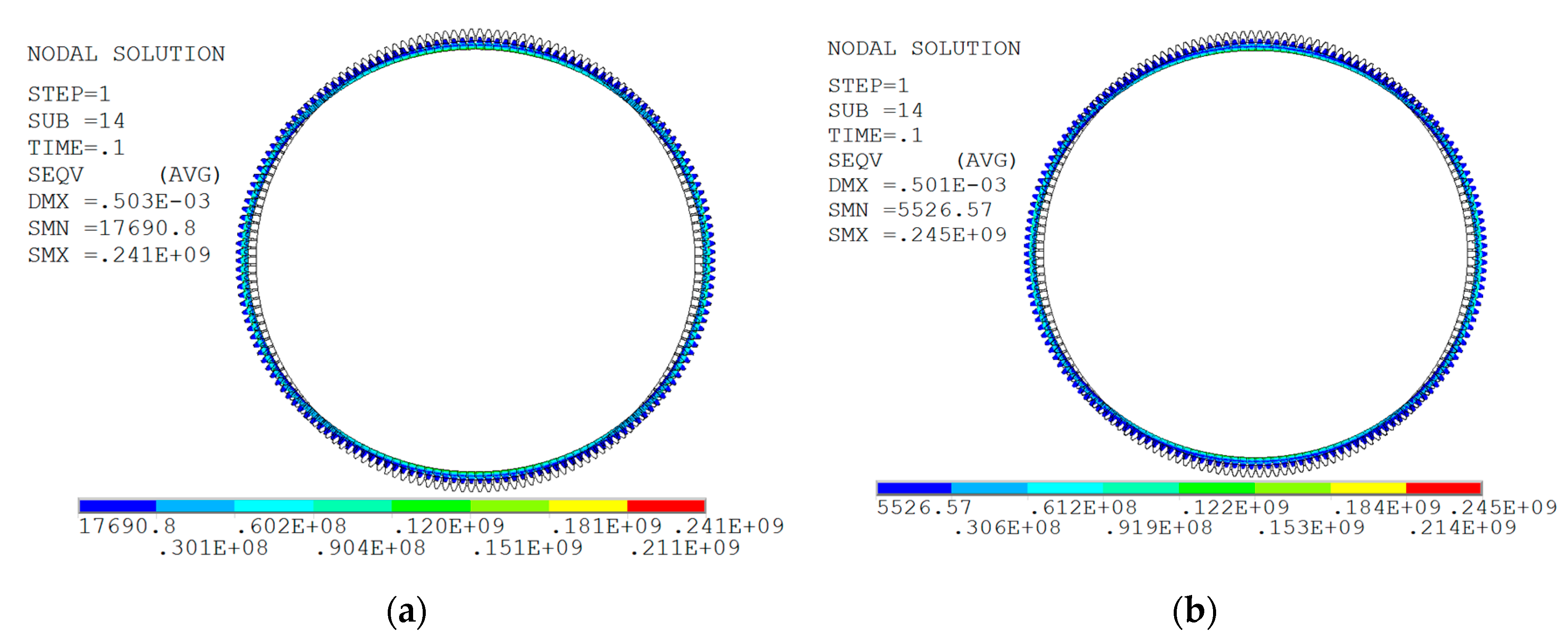
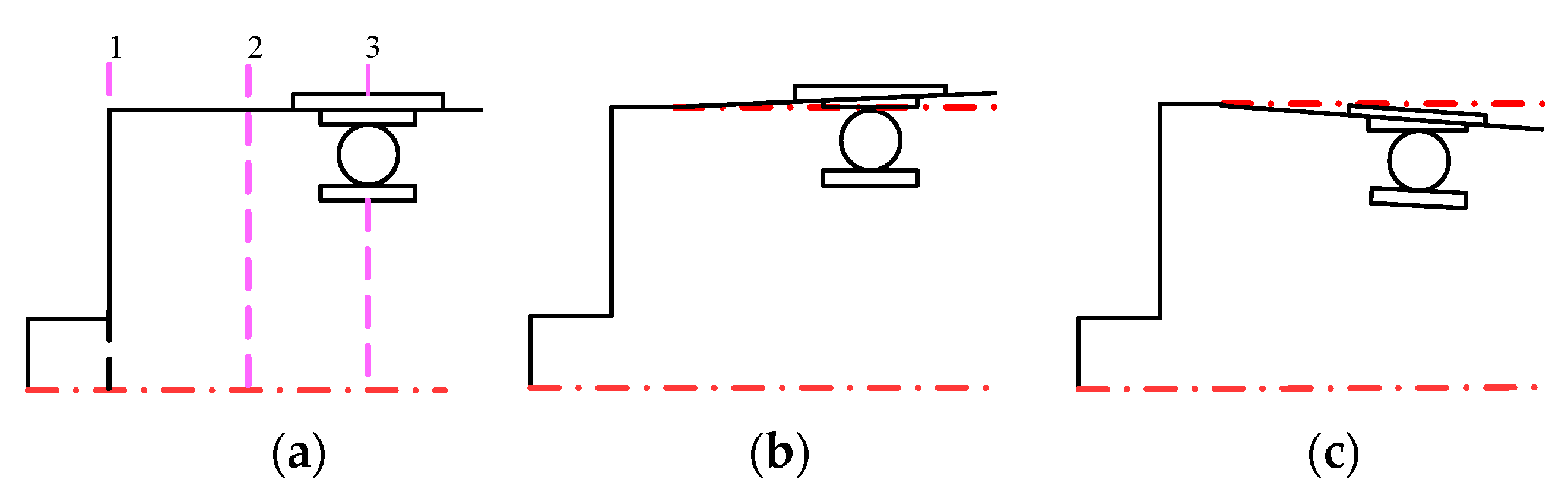
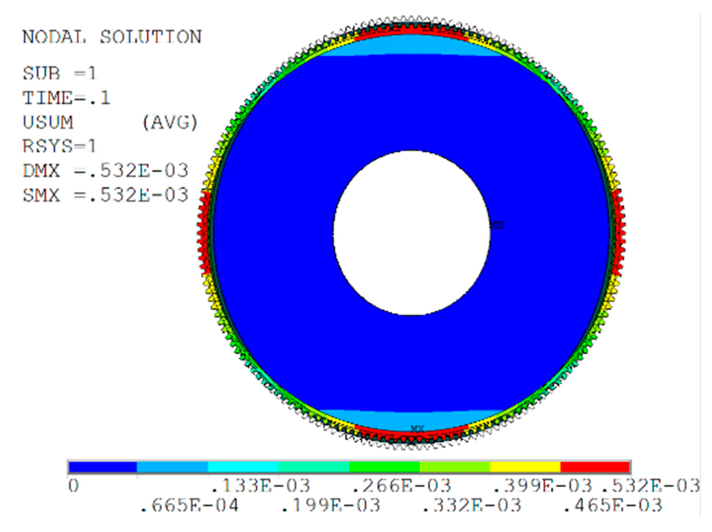
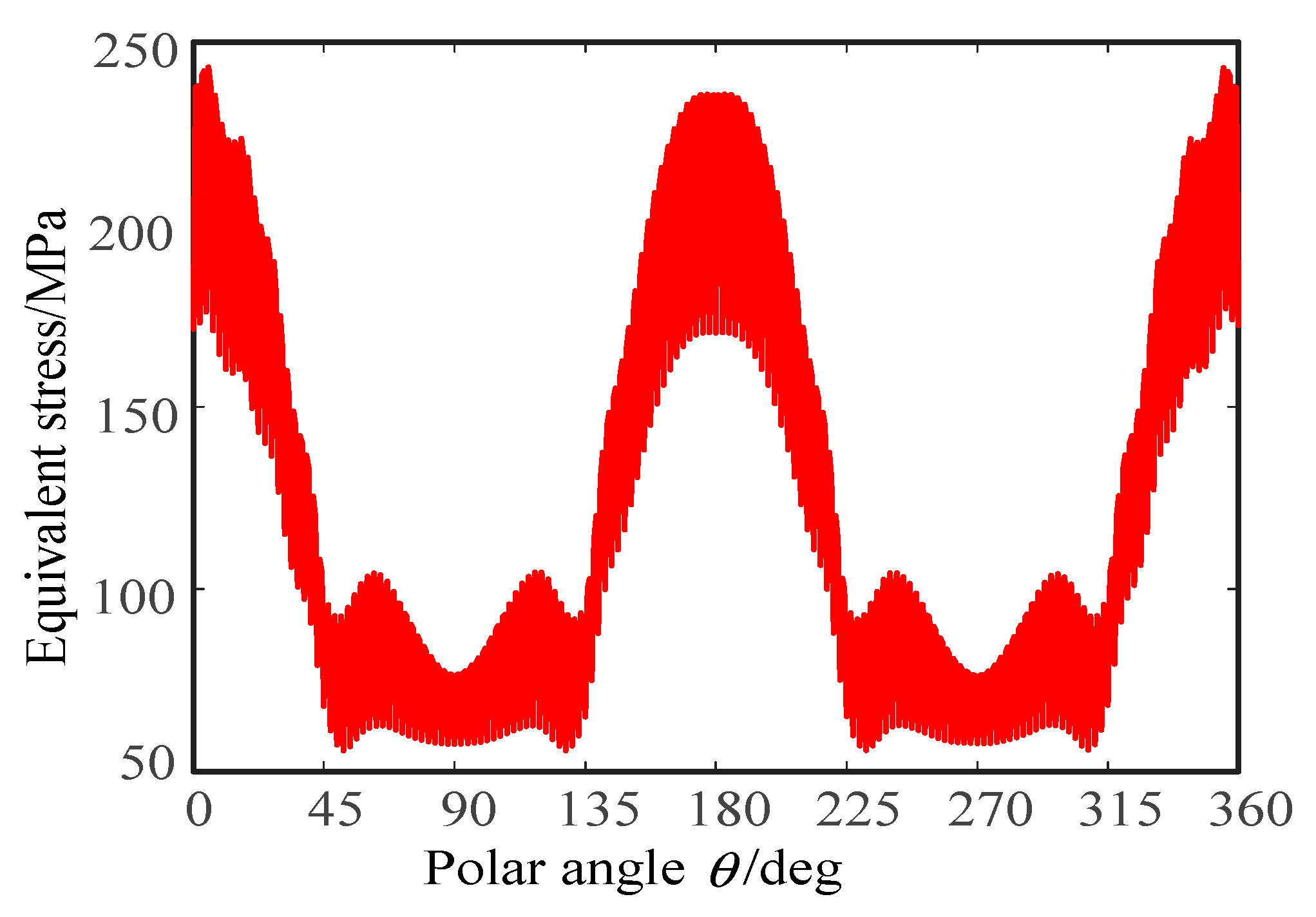
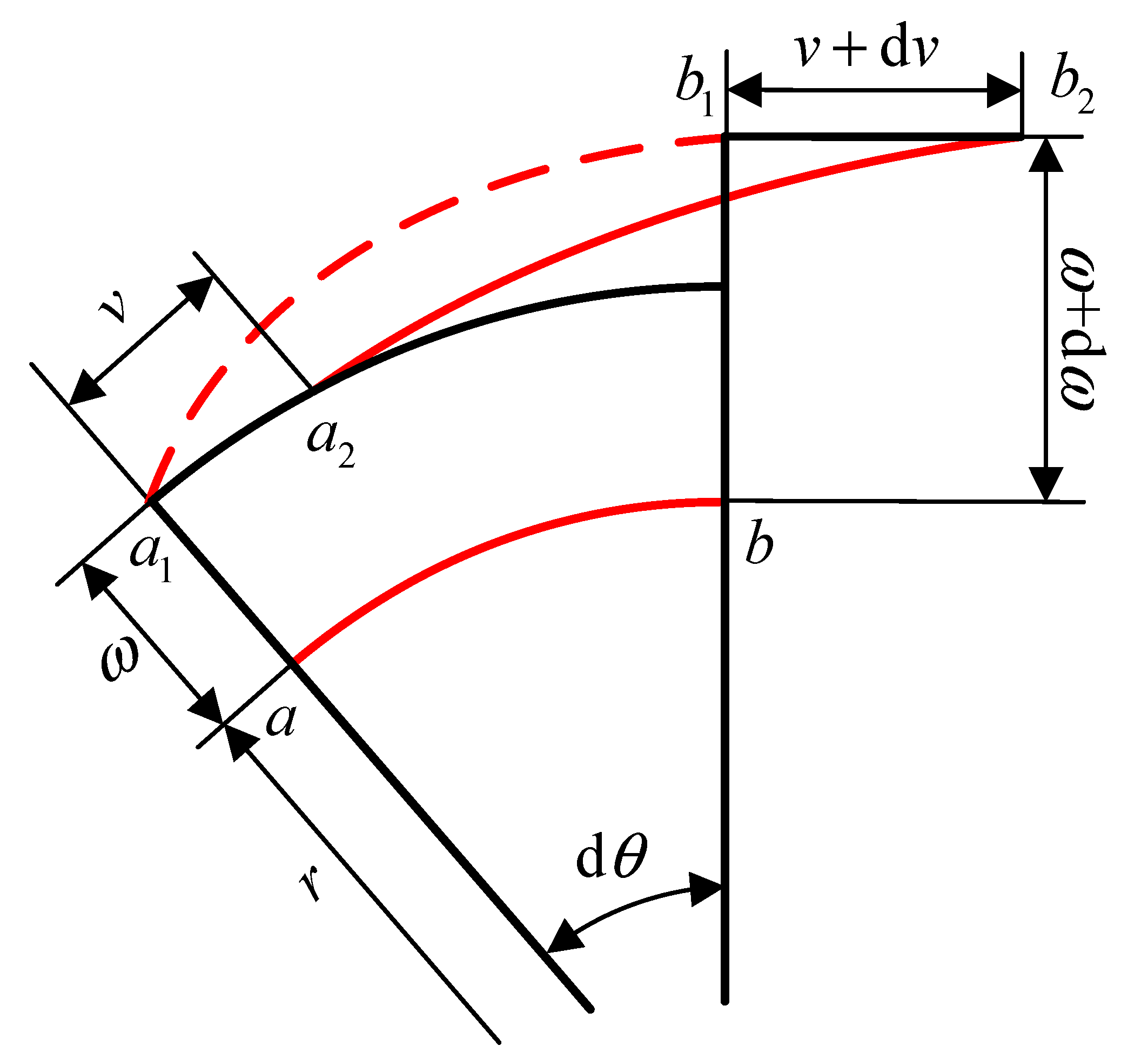
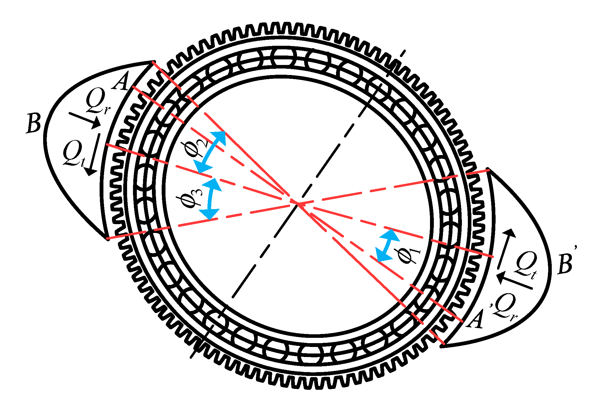
3.2. Mechanical Analysis of the Flexspline under Cosine Cam

When the flexspline is assembled with the cosine cam wave generator, the neutral layer section of the flexspline will be deformed along the generatrix direction. The shape changes of the flexspline and wave generator before and after assembly are shown in Figure 7.
As can be seen from Figure 7, in the long axis area of the wave generator, the flexspline is deformed and inclined to the outside, while in the short axis area of the wave generator, the flexspline is inclined to the inside. Moreover, the deformation of each section of flexspline is different along the axial direction.
In order to quantitatively analyze the displacement and stress distribution of the flexspline under the action of cosine cam, the static analysis of the flexspline was carried out. Fixed constraints are imposed on all the nodes of the inner hole surface of the flange at the bottom of the flexspline, and then the left and right half cams are controlled to move 0.5 mm along the negative and positive directions of x axis to simulate the assembly process of the flexspline and cosine cam. Finally, the augmented Lagrange algorithm [21] is used to solve the problem. The displacement nephogram of the flexspline under the action of the cosine cam and the equivalent stress distribution curve of the middle section of gear ring are shown in Figure 8 and Figure 9, respectively.
As can be seen from Figure 8 and Figure 9, the cross-sectional shape of the flexspline is greatly deformed under the action of cosine cam. The unit near the x-axis moves outward and the unit near the y-axis moves inward. The maximum displacement is 0.532 mm, which is slightly larger than the maximum radial deformation of the flexspline by 0.5 mm. The distribution curve of equivalent stress in the middle section of the flexspline ring gear is symmetrical with respect to the coordinate axes. The equivalent stress value near the x-axis direction is the largest, about 250 MPa, and the equivalent stress value near the y-axis direction is the smallest, about 50 MPa.
In order to further analyze the displacement of flexspline at different sections and polar angles, a circular path is defined along the counterclockwise direction with the forward direction of x axis as the starting point. Displacement data at the bottom (Z = 0) of the flexspline in Section 1, the middle (Z = 35) of the flexspline in Section 2 and the middle (Z = 63) of the ring gear in Section 3 were extracted as shown in Figure 7, and the results are shown in Figure 10.
It can be seen from Figure 10 that the greater the axial distance from the bottom of the flexspline, the greater the radial displacement and circumferential displacement of the corresponding points in the neutral layer of the flexspline. Although the numerical values are different, the variation trend of the displacement along the circumferential direction satisfies the sine and cosine variation law. The axial displacement at different sections is almost constant, because the flexspline is in an alternating stress state during the contact between the wave generator and the flexspline, and its circumferential stress and tangential stress are much greater than the axial stress, so the axial displacement is small and relatively stable. The total displacement is similar to the radial displacement and axial displacement. The displacement is the largest at the major and minor axes of the wave generator, and the smallest at θ = 45°, 135°, 225°, 315°, which is in accord with the characteristics of the cosine cam profile.

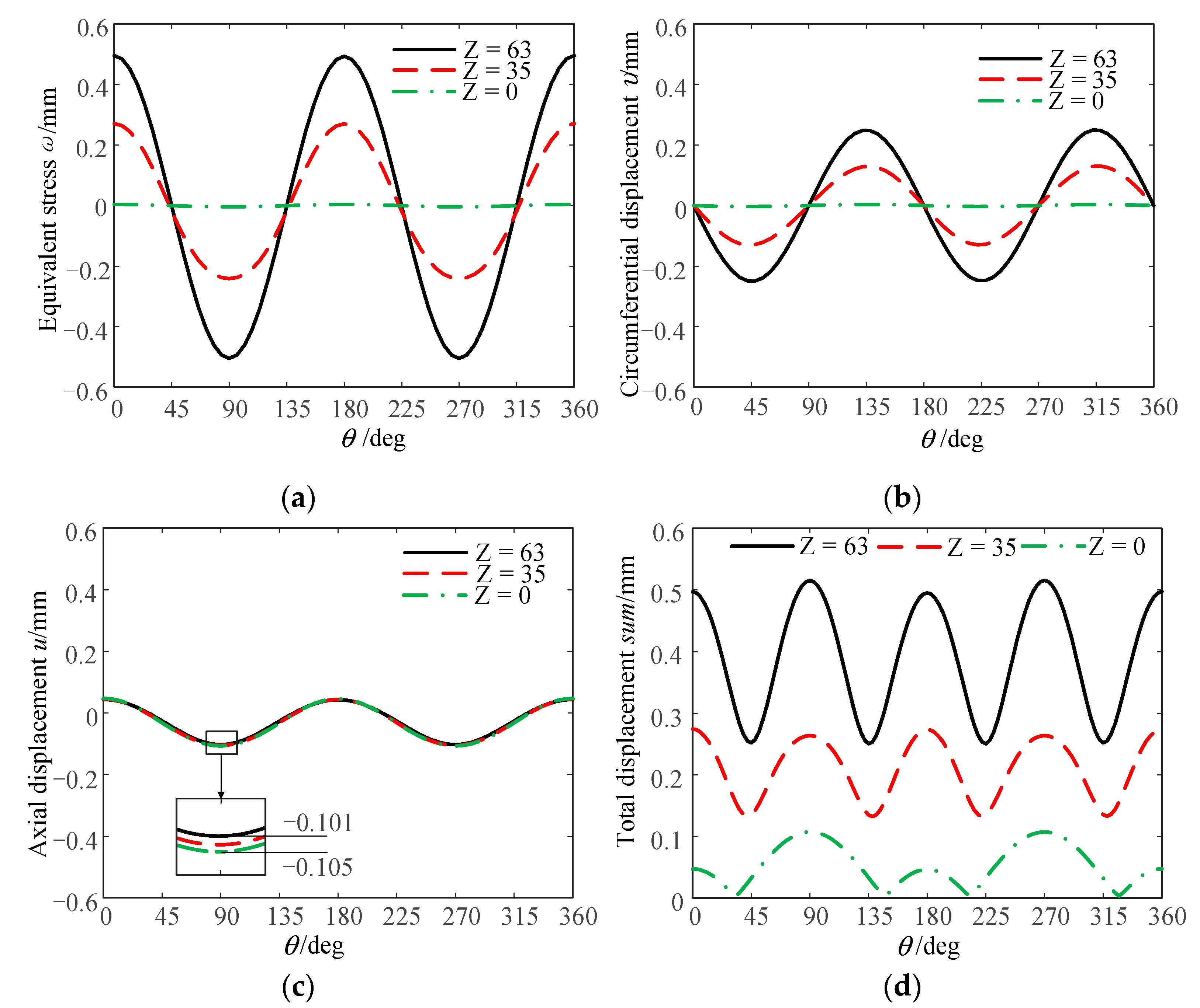
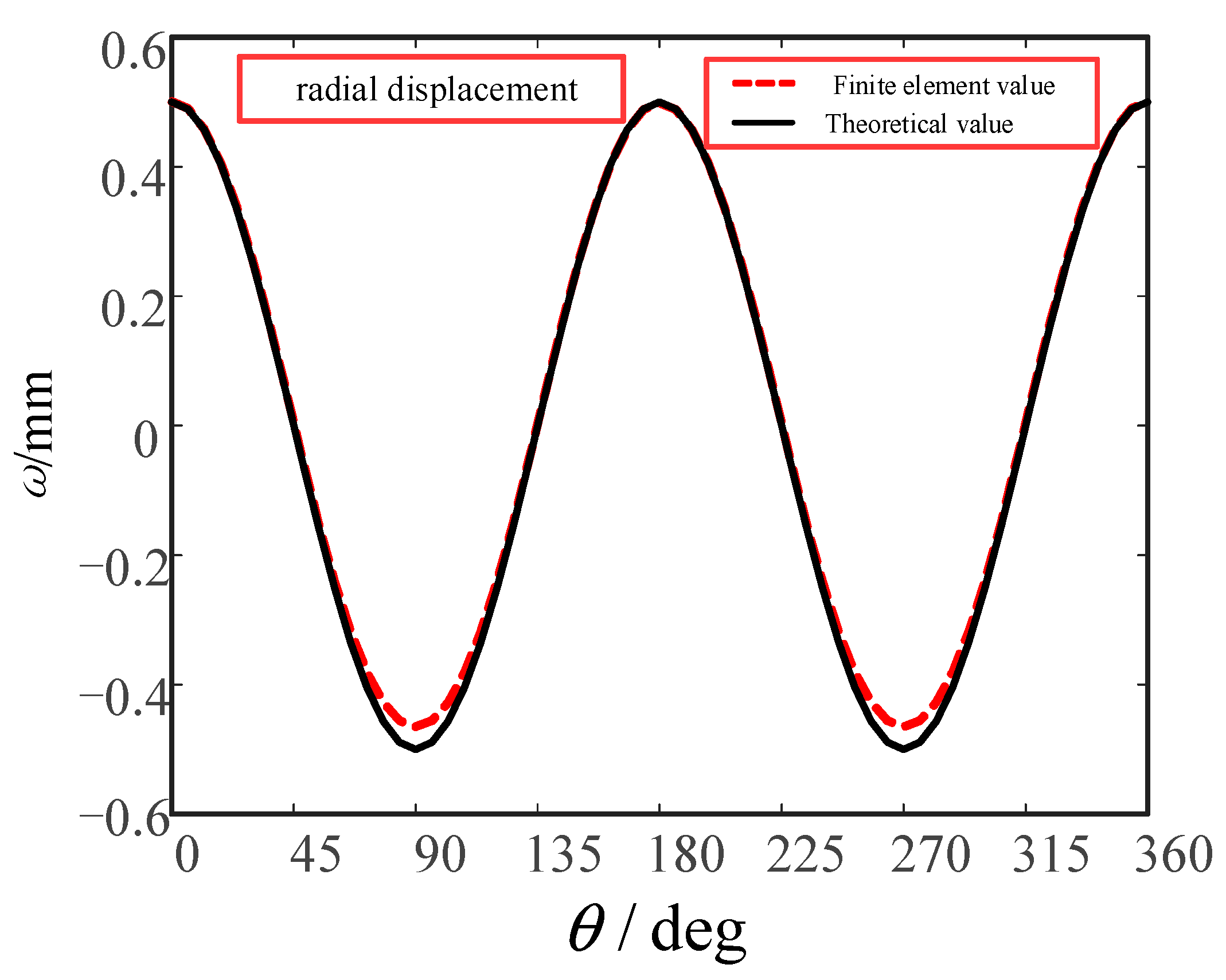
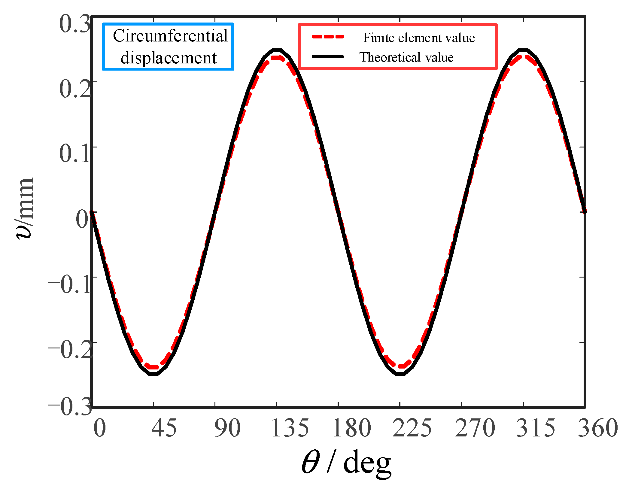
3.3. Comparison between Simulation Results and Theoretical Calculations

According to the polar coordinate equation of the cosine cam wave generator profile described above, the radial displacement at any point of the flexspline can be determined by the following functional relationship:
ω = 0.5 Z cos ( 2 θ ) / L
The displacement of the neutral layer line element during flexspline deformation is shown in Figure 11, and the line element a b is displaced to a 2 b 2 under the action of cam wave generator. This process can be divided into two stages: first, the line element a b is displaced radially ω and ω + d ω to a 1 b 1 ; and second, the circumferential displacement v and v + d v to a 2 b 2 takes place. The increment of line element length in the first stage is d ω , and the increment of line element length in the second stage is d υ .
Assuming that the neutral layer section of the flexspline is not elongated and the bus bar is not twisted, the sum of the length increments of line elements should be zero [1], so there are:
d ω + d υ = 0
The circumferential displacement at any point of the flexspline can be expressed as:
υ = 0 θ ω d θ
υ = Z sin ( 2 θ ) / ( 4 L )
where θ is the position angle between any point on the section of the neutral layer of the flexspline and the line connecting the center of the circle and the long axis of the wave generator, Z is the axial distance from any point on the section of the neutral layer of the flexspline to the bottom of its cylinder, and L is the length of the flexspline cylinder.
Axial displacement and angular displacement at any point of flexspline can be expressed as:
{ u = R c o s ( 2 θ ) / ( 8 L ) ϕ = 3 Z sin ( 2 θ ) / ( 4 R L )
where R is the cross-sectional radius of the neutral layer of the flexspline.
In order to more intuitively find out the relationship between radial displacement, circumferential displacement, axial displacement and angular displacement of the flexspline and polar angle and axial distance from the cylinder to cylinder bottom, the spatial distribution state diagram of flexspline displacement was projected in plane, as shown in Figure 12.
It can be seen from Figure 12 that the spatial distribution state diagram of the radial displacement, circumferential displacement and angular displacement of the flexspline of the harmonic gear reducer has a similar shape layout in each plane, and the xoy plane projection is a rectangular layout, the xoz plane projection is a triangular layout, and the yoz plane projection is a sine–cosine waveform layout. The plane projection drawings of axial displacement are different. The xoy and xoz plane projections are both a rectangular layout, while the yoz plane projection is a sine–cosine curve layout. This is because the axial displacement value does not change with the axial distance Z between the cylinder and the cylinder bottom, so its yoz plane projection is a sine–cosine curve, and the different colors in each plane projection represent the different displacement values.
The theoretical values of the radial and circumferential displacements of the flexspline of a harmonic gear reducer at the middle of the flexspline ring gear (Z = 63) are extracted and compared with the simulation values of the finite element analysis results. The results are shown in Figure 13 and Figure 14.
It can be seen from Figure 13 and Figure 14 that the theoretical and finite element values of the radial displacement of the neutral layer of the flexspline are different around θ = 90 and 270, that is, the finite element values of the radial displacement near the short axis of the wave generator are slightly smaller than the theoretical values, and the finite element values at other positions are basically consistent with the theoretical values. The finite element values of the circumferential displacement are slightly smaller than the theoretical values at the positions of θ = 45, 135, 225 and 315, and are basically consistent at other positions. The reason for this phenomenon is that the theoretical value is calculated on the premise that the neutral layer does not elongate, and when the finite element simulation analysis is carried out, the neutral layer of flexspline will change, and the elongation of the neutral layer leads to a slight difference between the finite element value and the theoretical value at these positions [22].
By comparing the theoretical solution of radial displacement and circumferential displacement with the finite element simulation results, it can be seen that the finite element simulation results of the radial displacement and circumferential displacement of the neutral layer of the flexspline are in good agreement with the theoretical solution. At the same time, the correctness of the finite element model established in this paper is also verified.

4. Sensitivity Calculation of Stress Characteristics and Fatigue Life Analysis of the Flexspline

4.1. Calculation of Meshing Force of the Flexspline Teeth

Referring to [7], the distribution law of flexspline tooth meshing force of a harmonic gear reducer can be obtained: the load distribution of flexspline is shown in Figure 15, and the meshing force of flexspline teeth can be approximately expressed by Equations (8) and (9).
In the area where ϕ 2 , ϕ 3 are located, the meshing force between the flexspline and rigid wheel can be expressed as Equations (8) and (9):
{ Q t = Q tmax cos [ π ( ϕ ϕ 1 ) / ( 2 ϕ 2 ) ] Q r = Q t tan α
{ Q t = Q tmax cos [ π ( ϕ ϕ 1 ) / ( 2 ϕ 3 ) ] Q r = Q t tan α
The load Q on the single tooth surface of the flexspline is:
Q = B f Q t 2 + Q r 2
The relationship between moments T and Q tmax is as follows:
T = ϕ 1 ϕ 1 + ϕ 2 D f 2 B f Q tmax cos [ π ( ϕ ϕ 1 ) / ( 2 ϕ 2 ) ] d ϕ
After the integral operation, the relationship between Q tmax and torque T is obtained:
Q tmax = π T / ( 2 ϕ 2 D f 2 B f )
where Q t is the circumferential load on the unit tooth width of the flexspline, ϕ is the angle between the long axis A A of the wave generator and the load, Q r is the radial load on the unit tooth width of the flexspline, ϕ 1 is the angle between the long axis A A of the wave generator and the load symmetry axis B B , α is the tooth meshing angle, ϕ 2 , ϕ 3 are the meshing area angles, T is the torque borne by the flexspline, D f is the diameter of the indexing circle of the flexspline, B f is the width of the flexspline ring gear, Q tmax is the maximum value of the tangential component of the meshing force of the flexspline teeth, and Q is the load value on the tooth surface of a single flexspline tooth.
When ϕ 1 π / 12 and ϕ 2 = ϕ 3 π / 8 , the angle of meshing area is −5π/24~π/24 and 19π/24~25π/24, respectively. According to the Equations (8)–(12), the load values at different meshing area angles ϕ of the flexspline teeth under normal load (torque T is 70 N·m, 80 N·m and 90 N·m) and overload (torque T is 100 N m and 110 N m) are calculated. From the load distribution diagram of the flexspline, it can be seen that the meshing area of gear teeth has a certain symmetry, and its size is π/4, so only the load value of the meshing area at −5π/24~π/24 is calculated.
For the convenience of the follow-up research, the meshing area −5π/24~π/24 is divided into 20 parts according to the interval of π / 80 , and 21 load values are calculated. Then, the calculated load values are loaded on the tooth surfaces of 21 teeth of flexspline in turn during the finite element analysis. Under different torques, the load values at the angle ϕ of each meshing area of flexspline teeth are shown in Table 1.

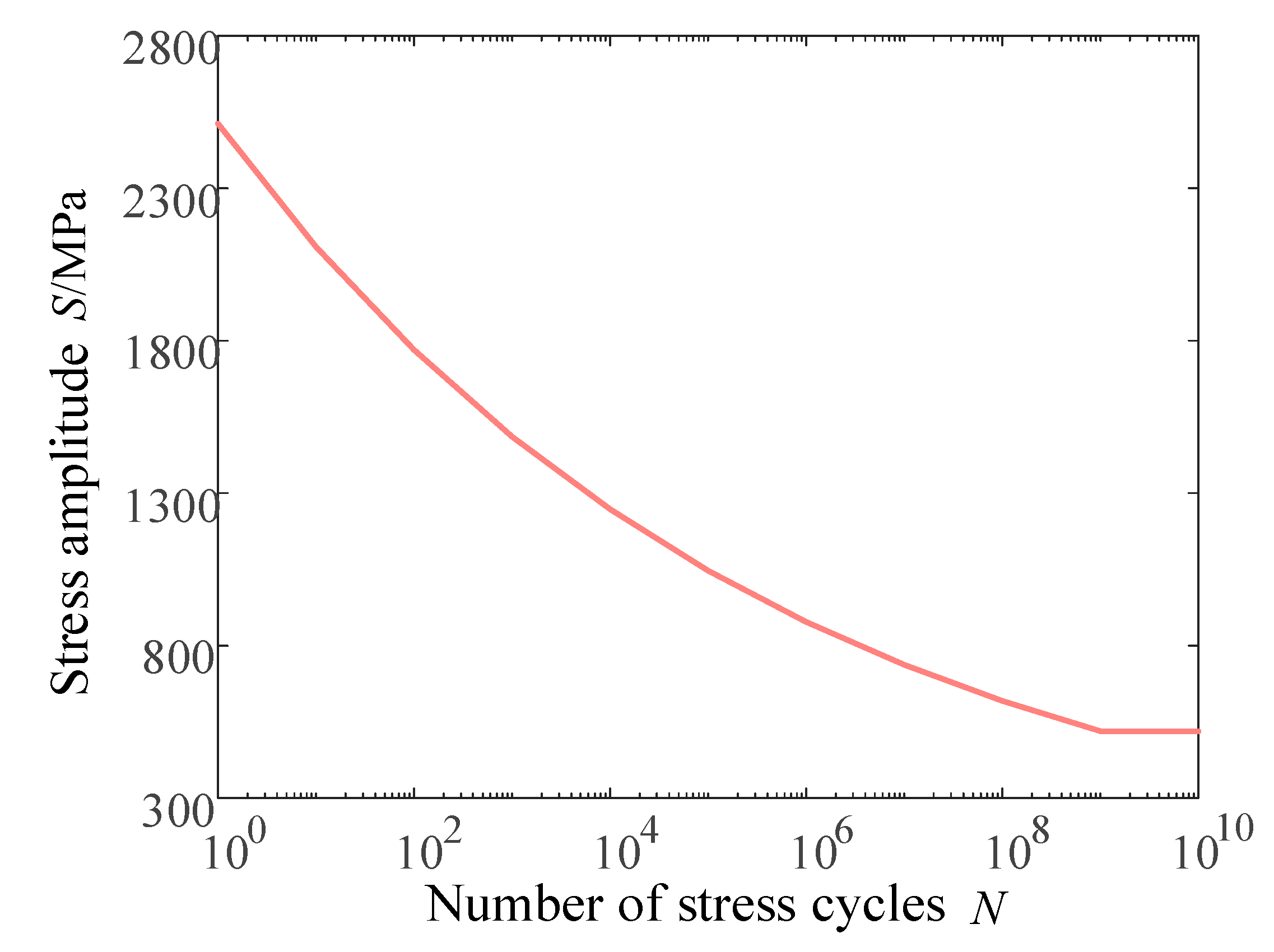
4.2. Fatigue Life Analysis of the Flexspline

The fatigue failure of the materials is usually divided into three stages: initial crack initiation, stable propagation in the middle stage and unstable propagation to fracture failure in the later stage. The fatigue performance of any material can be described by the relationship between its bearing stress S and its life N when fatigue damage occurs. From the 1950s to 1960s, Waller first put forward the concept of fatigue limit, and obtained the S–N curve describing fatigue behavior and characterizing fatigue performance. Among them, the double logarithmic linear relationship of the S–N curve described by a power function can be expressed by Equation (13) [23,24].
lg S = 1 m ( lg C lg N )
In the formula, m, C are the parameters related to the properties of the tested materials, loading methods, stress ratios, etc.
The rated working time of the flexspline is closely related to the stress it bears. Therefore, the S–N curve of the 30CrMnSi material should be determined first when analyzing the fatigue life of the flexspline. The S–N curve of the material can be obtained by theoretical derivation calculation or experiment, and then the S–N curve of the flexspline material 30CrMnSi is finally obtained by calculation in combination with Equation (13) as shown in Figure 16 [25,26].

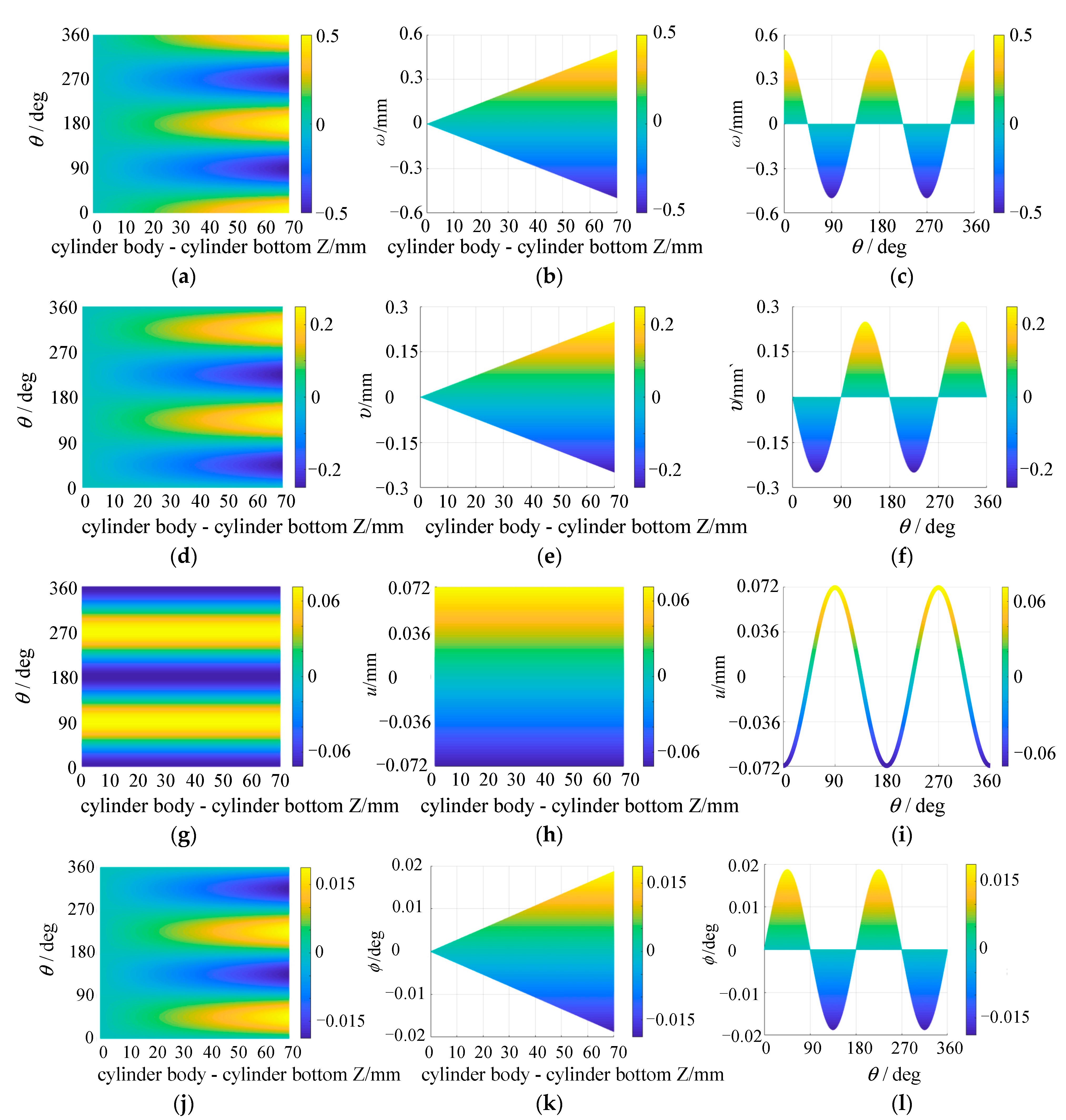
4.3. Analysis of the Influence of Cylinder Length on the Flexspline

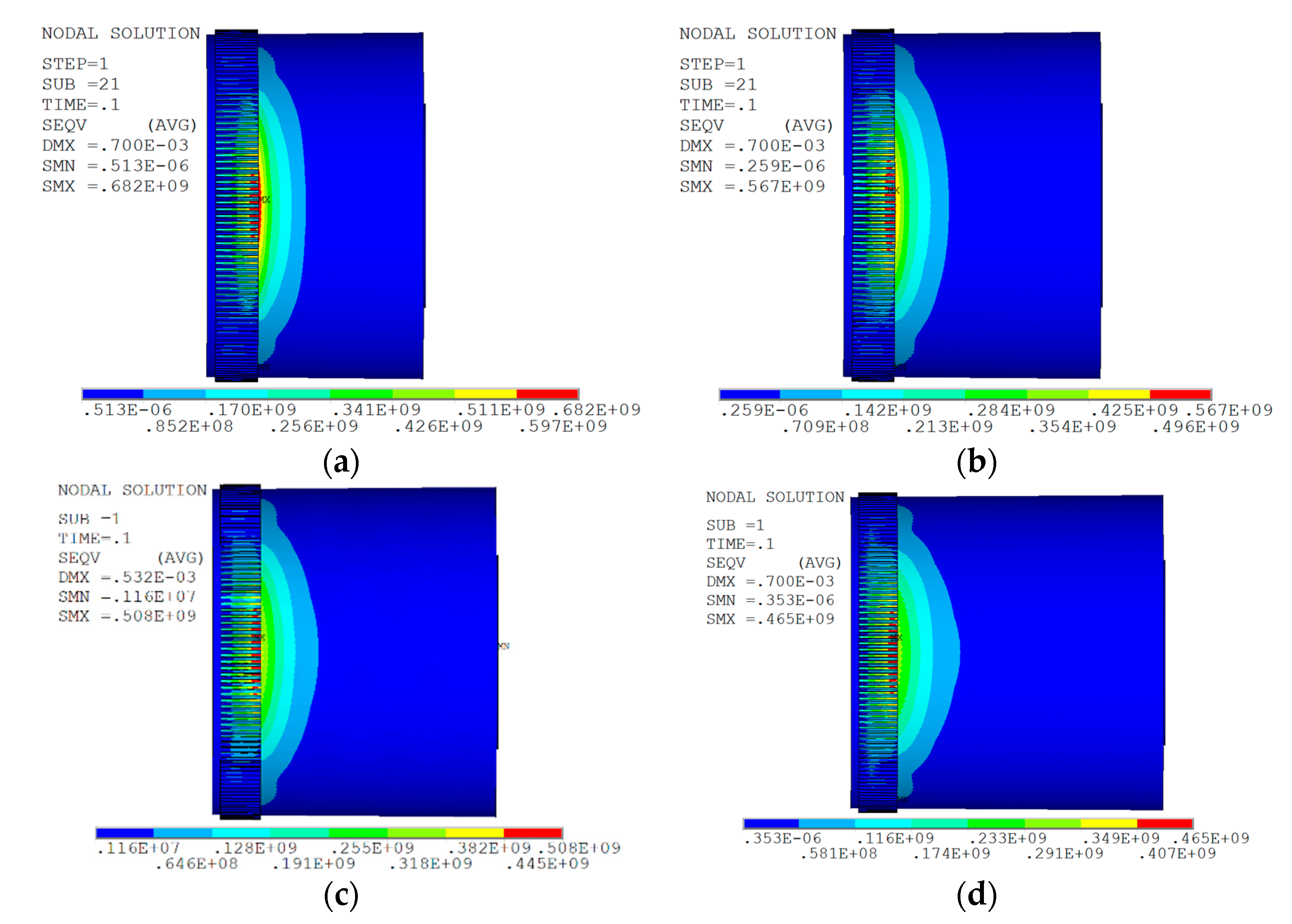
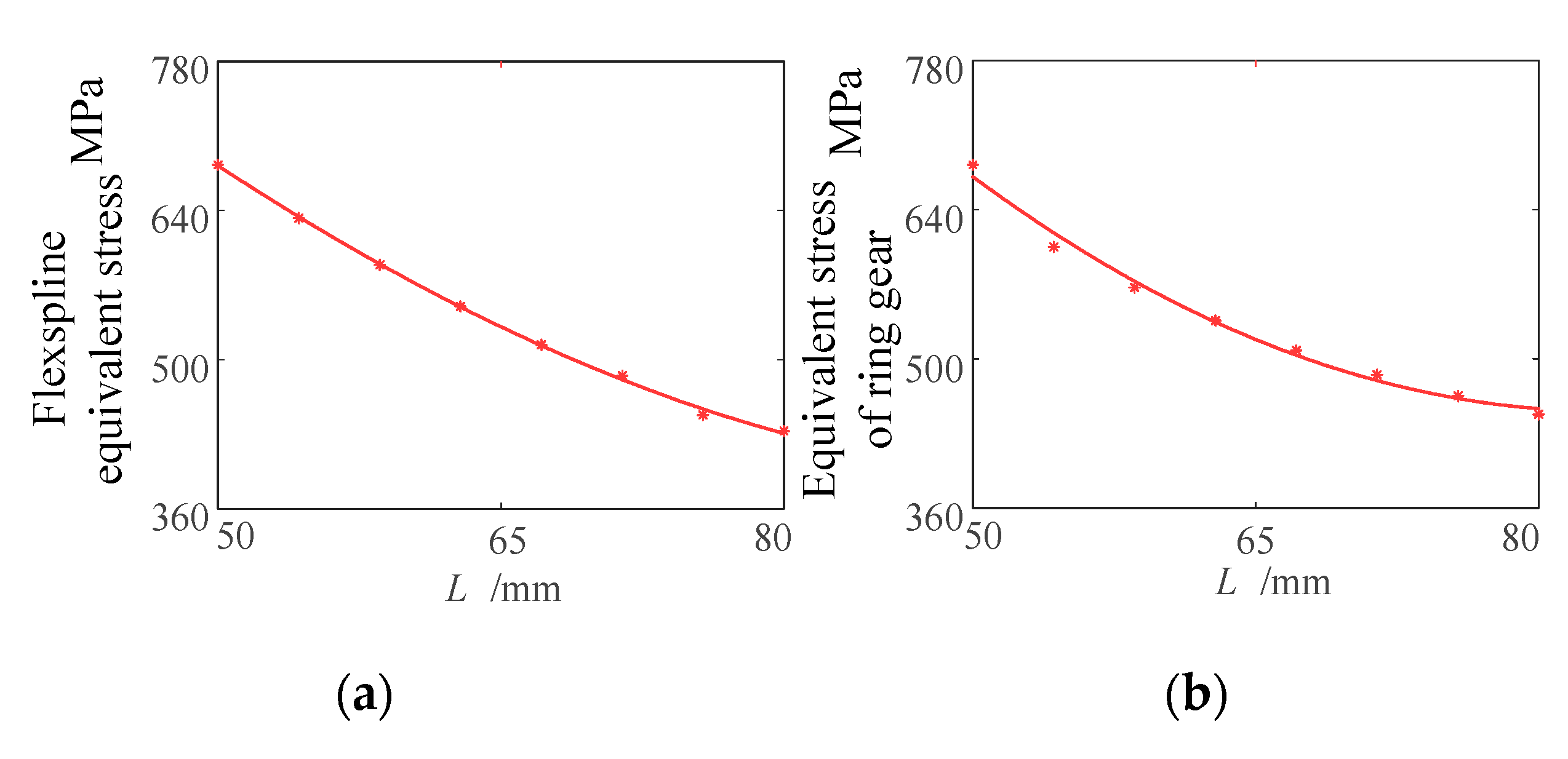
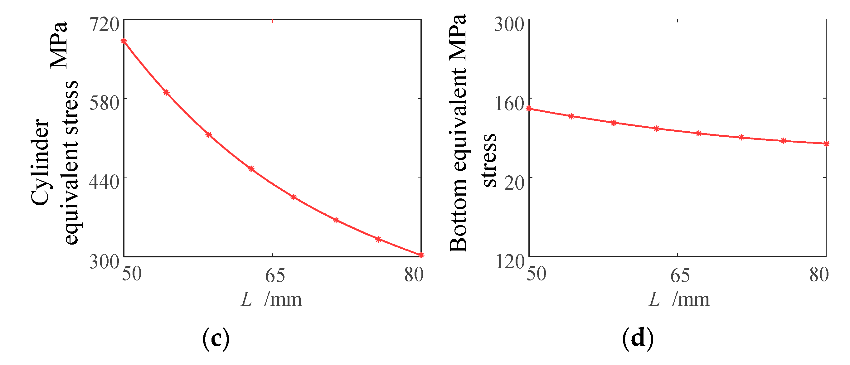
4.3.1. Analysis of the Influence of Cylinder Length on Flexspline Stress

The length L of the cylinder determines the geometrical dimension of the flexspline in the axial direction and is one of the key structural parameters of the cylindrical cup-shaped flexspline, which has a significant influence on the mechanical characteristics of the flexspline [27,28]. Therefore, in this section, the length range of cylinder is L = 50~80 mm, and the value is taken every 10 mm, and four groups of analysis are carried out altogether. The stress nephogram of flexspline under different cylinder lengths is shown in Figure 17.
As can be seen from Figure 17, when the length of the flexspline cylinder increases from 50 mm to 80 mm, its maximum equivalent stress value decreases by 32%, indicating that the increase in the cylinder length L can improve the stress of the flexspline.
The fitting curve of the analysis results is shown in Figure 18. If the flexspline is divided into three parts, ring gear, smooth cylinder and flexspline bottom, the stress value of ring gear and smooth cylinder is greater than that of flexspline bottom. When L = 50~70 mm, the maximum equivalent stress values of flexspline ring gear, smooth cylinder and flexspline bottom decrease evidently, from 683 MPa to 514 MPa, 682 MPa to 365 MPa, 142 MPa to 98.1 MPa, respectively. When L = 70~80 mm, the decreasing trend of the maximum equivalent stress value tends to be flat, from 514 MPa to 488 MPa, 406 MPa to 303 MPa, 98.1 MPa to 79.2 MPa, respectively. It shows that, with the increase in the length of the cylinder, the stress concentration of the flexspline decreases, and the stress of the flexspline can be improved by increasing the length of the cylinder.

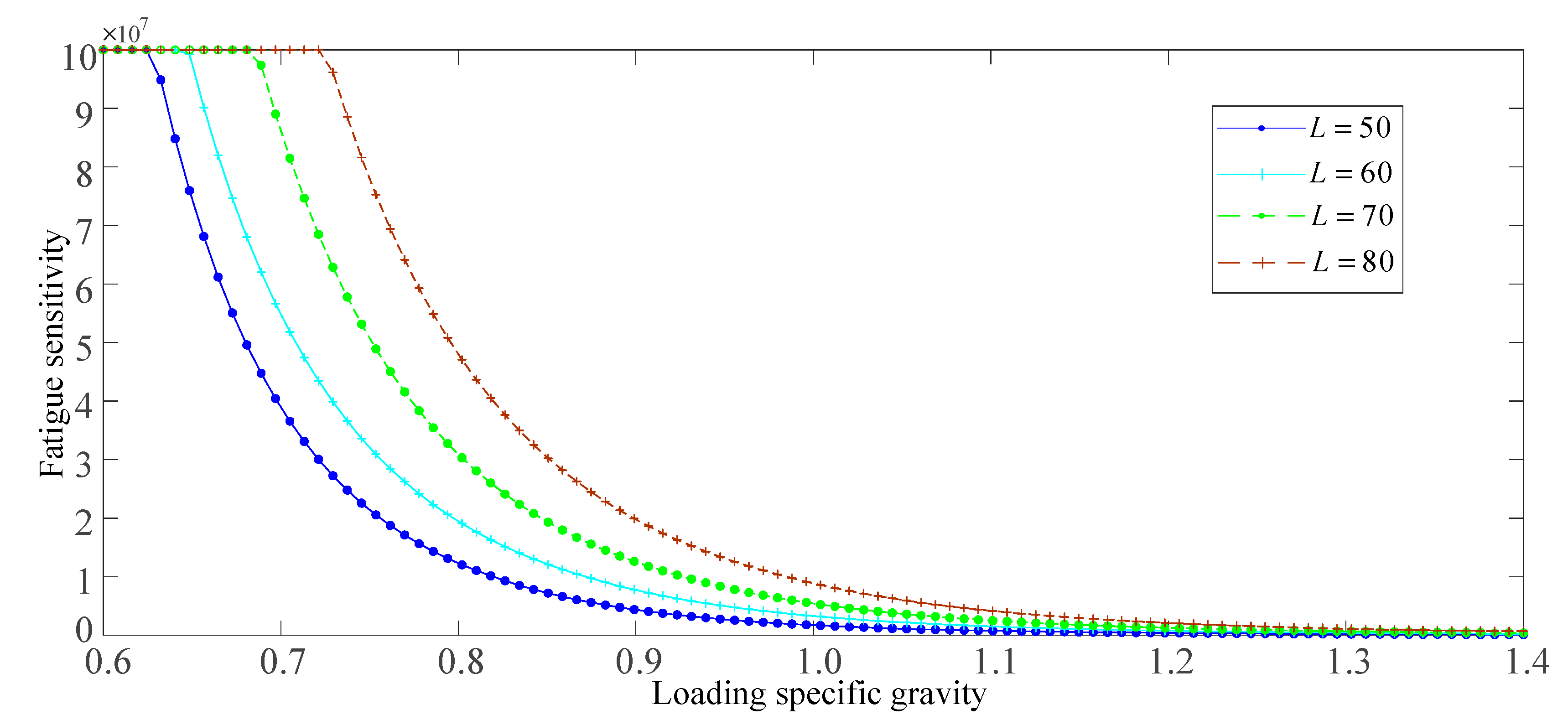
4.3.2. Influence of Cylinder Length on Fatigue Life

From the above analysis, it can be seen that, with the increase in cylinder length L, the maximum equivalent stress value of flexspline decreases. In this section, the range of cylinder length L = 50~80 mm is taken, and the value is taken every 10 mm, so as to analyze the relationship between the fatigue life of the flexspline and cylinder length. The influence law of loading specific gravity on the fatigue characteristics of the flexspline under different cylinder lengths is shown in Figure 19.
As can be seen from Figure 19, when the cylinder length L is constant, with the increase in loading specific gravity from 60% to 140%, the fatigue sensitive characteristic curve of the flexspline tends to be more and more flat. When the loading specific gravity is constant, with the increase in cylinder length L, the fatigue sensitive characteristic curve of the flexspline moves to the upper right as a whole, indicating that the increase in the cylinder length is beneficial to prolong the fatigue life of the flexspline.

4.4. Analysis of the Influence of Smooth Cylinder Wall Thickness on the Flexspline

4.4.1. Analysis of the Influence of Smooth Cylinder Wall Thickness on Flexspline Stress

In order to analyze the influence of smooth cylinder wall thickness δ on the mechanical characteristics of the flexspline, the finite element model was analyzed by changing the value of δ separately, while keeping other parameters unchanged. In this section, the smooth cylinder wall thickness δ = 0.74~0.86 mm, and the value is taken every 0.04 mm. The stress nephogram of the flexspline with different smooth cylinder wall thicknesses is shown in Figure 20.
It can be seen from Figure 20 that, when δ = 0.74 mm, the maximum equivalent stress value of the flexspline is 497 MPa, and when δ = 0.86 mm, the maximum equivalent stress value of flexspline is 538 MPa, which increases by 8.2%. The fitting curve of the analysis results is shown in Figure 21.
It can be seen from Figure 21 that, in the range of δ = 0.74~0.88 mm, the maximum equivalent stress value of the ring gear part decreases first and then increases, and when δ = 0.82, the maximum equivalent stress value of the ring gear part is the smallest, and its size is 514 MPa. The maximum equivalent stress value of the cylindrical part decreases linearly and decreases from 410 MPa to 400 MPa when δ increases from 0.74 to 0.86. The maximum equivalent stress value of the cylindrical part decreases from 410 MPa to 400 MPa, when δ increases from 0.74 to 0.86. The maximum equivalent stress at the base of the flexspline is almost unaffected by the wall thickness of the cylinder, and its value fluctuates around 98.1 MPa.

4.4.2. Influence of Wall Thickness of Smooth Cylinder on Fatigue Life

From the above analysis, it can be seen that, with the increase in smooth cylinder wall thickness δ , the maximum equivalent stress value of the flexspline ring gear part decreases first and then increases, while the maximum equivalent stress value of the cylinder part approximately decreases linearly, but the decreasing trend is not evident, and the maximum equivalent stress value of the flexspline bottom is almost unchanged. Taking δ = 0.74~0.86 mm, and taking values every 0.04 mm, we analyzed the relationship between flexspline fatigue life and smooth cylinder wall thickness. The influence law of loading specific gravity on flexspline fatigue characteristics under different cylinder wall thickness is shown in Figure 22.
It can be seen from Figure 22 that the fatigue sensitivity curve of the flexspline tends to be more and more flat with the increase in loading specific gravity from 60% to 140% when the wall thickness of smooth cylinder is constant. When the loading specific gravity is constant, the fatigue sensitivity curve of the flexspline almost remains unchanged with the increase in the wall thickness of the smooth cylinder. The section of fatigue sensitive characteristic curve with loading specific gravity of 80~100% is observed, and it can be seen that the curve corresponds to δ = 0.74, 0.78, 0.82 and 0.86 from top to bottom, that is, the wall thickness of the cylinder bottom hardly affects the fatigue life of the flexspline.

5. Conclusions

The structure design of a B3-80 general harmonic gear reducer flexspline was completed by using finite element software. The finite element model of the flexspline was established, and the static simulation analysis of the flexspline was carried out. By changing the length of the flexspline cylinder, the wall thickness of the flexspline cylinder bottom and the wall thickness of the smooth cylinder, the influence of the length of the flexspline cylinder and the wall thickness of the smooth cylinder on the fatigue life of the flexspline was analyzed. The following conclusions were obtained:
(1)
With the increase in the length of the cylinder, the maximum equivalent stress value of the flexspline decreases and the service life is evidently prolonged. Therefore, the stress condition of the flexspline can be improved by increasing the length of the cylinder, but the increase in the cylinder length will lead to an increase in volume and a decrease in torsional stiffness.
(2)
With the increase in smooth cylinder wall thickness, the maximum equivalent stress value of the flexspline body increases, but the increasing trend is not evident.
(3)
Compared with the wall thickness at the bottom of the cylinder and the wall thickness of the smooth cylinder, the length of the flexible cylinder has a greater impact on its fatigue life. The increase in flexible wheel cylinder length can significantly prolong its service life, but the increase in flexible wheel cylinder length will lead to an increase in volume and a decrease in torsional stiffness.

Author Contributions

Conceptualization, H.Y.; Data curation, J.X.; Formal analysis, X.L.; Investigation, H.Y.; Methodology, H.Y.; Software, H.Y., J.X. and Y.G.; Supervision, X.L. and B.L.; Validation, J.X., Y.G. and B.L.; Visualization, J.X. and Y.G.; Writing—original draft, H.Y.; Writing—review & editing, X.L. All authors have read and agreed to the published version of the manuscript.

Funding

This research was funded by Natural Science Foundation of Ningxia Province (No. 2020AAC03279) and Ningxia Advanced manufacturing technology research talents small highland (20181213).

Institutional Review Board Statement

Not applicable.

Informed Consent Statement

Not applicable.

Data Availability Statement

Some data, models, or code generated or used during the study are available from the corre-sponding author by request.

Conflicts of Interest

The authors declare no conflict of interest.

References

  1. Shen, Y.W.; Ye, Q.T. Theory and Design of Harmonic Gear Drive; Mechanical Industry Press: Beijing, China, 1985. [Google Scholar]
  2. Jia, H.; Li, J.; Xiang, G.; Wang, J.; Xiao, K.; Han, Y. Modeling and analysis of pure kinematic error in harmonic drive. Mech. Mach. Theory 2021, 155, 104122. [Google Scholar] [CrossRef]
  3. Li, X.; Song, C.; Yang, Y.; Zhu, C.; Liao, D. Optimal design of wave generator profile for harmonic gear drive using support function. Mech. Mach. Theory 2020, 152, 103941. [Google Scholar] [CrossRef]
  4. Li, S. Diaphragm stress analysis and fatigue strength evaluation of the flex-spline, a very thin-walled spur gear used in the strain wave gearing. Mech. Mach. Theory 2016, 104, 1–16. [Google Scholar] [CrossRef]
  5. Pacana, J.; Witkowski, W.; Mucha, J. FEM analysis of stressdistribution in the hermetic harmonic drive flexspline. Strength Mater. 2017, 49, 388–398. [Google Scholar] [CrossRef]
  6. Routh, B.; Maiti, R.; Ray, A.K.; Sobczyk, A. An investigation on secondary force contacts of tooth pairs in conventional harmonic drives with involute toothed gear set. Proc. Inst. Mech. Eng. 2015, 230, 622–638. [Google Scholar] [CrossRef]
  7. Kayabasi, O.; Erzincanli, F. Shape optimization of tooth profile of a flexspline for harmonic drive by finite element modeling. Mater. Des. 2007, 28, 441–447. [Google Scholar] [CrossRef]
  8. Ostapski, W.; Mukha, I. Stress State Analysis of Harmonic Drive Elements by FEM. Tech. Sci. 2007, 55, 115–123. [Google Scholar]
  9. Ostapski, W. Analysis of the Stress State in the Harmonic Drive Generator Flexspline System in Relationto Selected Structural Parameters and Manufacturing Deviations. Bull. Pol. Acad. Sci. Tech. Sci. 2010, 4, 693–698. [Google Scholar]
  10. Feng, F.; Wang, W.; Tang, L.N.; Fengfan, C.; Yanwei, B.; Shanghai Aerospace Equipments Manufacturer. Application and development trend of space high precision harmonic reducer. Mech. Transm. 2014, 38, 98–107. [Google Scholar]
  11. Leno, D.; Arzola, N.; Tovar, A. Statistical analysis of the influence of tooth geometry in the performance of a harmonic drive. J. Braz. Soc. Mech. Sci. Eng. 2015, 37, 723–735. [Google Scholar] [CrossRef] [Green Version]
  12. Gravagno, F.; Mucino, V.H.; Pennestrì, E. Influence of wave generator profile on the pure kinematic error and centrodes of harmonic drive. Mech. Mach. Theory 2016, 104, 100–117. [Google Scholar] [CrossRef]
  13. Zhang, C.; Shao, Z.; Zhu, Y.; Li, J. Austenite grain refinement and homogenization control of the flexspline for industrial robot harmonic drive. J. Mater. Eng. Perform. 2021, 30, 4393–4400. [Google Scholar] [CrossRef]
  14. Xiao, Q.; Han, X.; Jia, H. Dynamic optimum design and analysis of cam wave generator for harmonic gear drive. In Proceedings of the International Conference on Information and Automation, Shenzhen, China, 6–8 June 2011; pp. 315–319.
  15. Ye, N.H.; Deng, X.; He, Y.; Sun, Y. Mechanical analysis and fatigue life study of harmonic flexspline. J. Hunan Univ. Nat. Sci. Ed. 2018, 45, 18–25. [Google Scholar]
  16. Ivanov, M.H.; Shen, Y.W. Harmonic Gear Drive; National Defense Industry Press: Beijing, China, 1987. [Google Scholar]
  17. Ishikawa, S. Tooth Profile of Spline of Strain Wave. U.S. Patent 4,823,638, 25 April 1989. [Google Scholar]
  18. Ishikawa, S.; Kiyosawa, Y. Flexing Contact Type Gear Driveof Non-Profile-Shifted Two-Circular-Arc Composite Tooth Profile. U.S. Patent 5,458,023, 17 October 1995. [Google Scholar]
  19. Si, C.G.; Fan, Y.G.; Lin, Z.N.; Zhang, H.Y. Harmonic Gear Drive; National Defense Industry Press: Beijing, China, 1978. [Google Scholar]
  20. Rao, Z.G. Design of Planetary Transmission Mechanism; National Defense Industry Press: Beijing, China, 1980. [Google Scholar]
  21. Li, L.; Luo, Z.; He, F.; Sun, K.; Yan, X. An improved partial similitude method for dynamic characteristic of rotor systems based on Levenberg–Marquardt method. Mech. Syst. Signal Process. 2022, 165, 108405. [Google Scholar] [CrossRef]
  22. Chen, X.X.; Liu, Y.S.; Xing, J.Z.; Xu, W. Expansion and contraction deformation law of flexspline neutral layer in harmonic gear. J. Mech. Eng. 2014, 50, 189–196. [Google Scholar] [CrossRef]
  23. Gao, H.B.; Li, Z.G.; Deng, Z.Q. Sensitivity analysis of structural parameters of cup-shaped flexspline to flexspline stress based on ANSYS. Proc. Mech. Eng. Soc. 2010, 46, 1–7. [Google Scholar]
  24. John, S. Harmonic drives provide high torque without backlash. Assembly 2005, 48, 8–15. [Google Scholar]
  25. Zhao, S.B. Anti-Fatigue Design Manual; Machinery Industry Press: Beijing, China, 2015. [Google Scholar]
  26. Zhang, A.G.; Zhu, C.J.; Chen, M.C. Fatigue, Fracture and Injury; Southwest Jiaotong University Press: Chengdu, China, 2006. [Google Scholar]
  27. Wu, Y. Fracture and Fatigue; China University of Geosciences Press: Wuhan, China, 2008. [Google Scholar]
  28. Gao, Z.T. Fatigue Test Design and Data Processing; Beijing University of Aeronautics and Astronautics Press: Beijing, China, 1999. [Google Scholar]
Figure 1. Structure diagram of the flexible wheel.
Mathematics 10 00868 g001
Figure 2. Finite element model of the flexible wheel.
Mathematics 10 00868 g002
Figure 3. Mesh model of the flexible wheel profile.
Mathematics 10 00868 g003
Figure 4. Simplified mesh model of the flexible wheel profile.
Mathematics 10 00868 g004
Figure 5. Flexible wheel deformation comparison. (a) Deformation nephogram before tooth profile mesh simplification. (b) Deformation nephogram after tooth profile mesh simplification.
Mathematics 10 00868 g005
Figure 6. Flexible wheel stress comparison of the front and rear of the tooth profile simplified mesh. (a) Stress nephogram before tooth profile mesh simplification. (b) Stress nephogram after tooth profile mesh simplification.
Mathematics 10 00868 g006
Figure 7. Diagram of the deformation of the flexible wheel structure before and after assembly. (a) Structure before assembly. (b) Long axis area structure after assembly. (c) Structure of short shaft area after assembly.
Mathematics 10 00868 g007
Figure 8. Displacement cloud chart of the flexible wheel.
Mathematics 10 00868 g008
Figure 9. Equivalent stress distribution curve of the section in the ring gear.
Mathematics 10 00868 g009
Figure 10. Deformation of the flexible wheel at different sections. (a) Radial displacement; (b) Circumferential displacement; (c) Axial displacement; (d) Total displacement.
Mathematics 10 00868 g010
Figure 11. Deformation of the flexible wheel neutral layer line element.
Mathematics 10 00868 g011
Figure 12. Flexible wheel displacement plane projection. (a) Radial displacement xoy; (b) Radial displacement xoz; (c) Radial displacement yoz; (d) Circumferential displacement xoy; (e) Circumferential displacement xoz; (f) Circumferential displacement yoz.; (g) Axial displacement xoy; (h) Axial displacement xoz; (i) Axial displacement yoz; (j) Angular displacement xoy; (k) Angular displacement xoz; (l) Angular displacement yoz.
Mathematics 10 00868 g012
Figure 13. Comparison of the radial displacement of the flexible wheel neutral layer.
Mathematics 10 00868 g013
Figure 14. Comparison of the circumferential displacement of the flexible wheel neutral layer.
Mathematics 10 00868 g014
Figure 15. Load distribution diagram of the flexible wheel.
Mathematics 10 00868 g015
Figure 16. S–N curve of 30CrMnSi.
Mathematics 10 00868 g016
Figure 17. Flexible wheels stress cloud chart of different round lengths. (a) L = 50 mm; (b) L = 60 mm; (c) L = 70 mm; (d) L = 80 mm.
Mathematics 10 00868 g017
Figure 18. Stress influence curve of different round length flexible wheels. (a) Stress variation curve of flexspline; (b) Stress change curve of the ring gear; (c) Cylinder stress change curve; (d) Bottom stress variation curve.
Mathematics 10 00868 g018aMathematics 10 00868 g018b
Figure 19. Effect of loading specific gravity on the fatigue characteristics of flexible wheels with different cylinder lengths.
Mathematics 10 00868 g019
Figure 20. Flexible wheels stress cloud chart of different smooth cylinder wall thickness. (a) = 0.74 mm; (b) = 0.78 mm; (c) = 0.82 mm; (d) = 0.86 mm.
Mathematics 10 00868 g020
Figure 21. Stress influence curve of the different smooth cylinder wall thickness of the flexible wheels. (a) Stress variation curve of the flexspline; (b) Stress change curve of the ring gear; (c) Cylinder stress change curve; (d) Bottom stress variation curve.
Mathematics 10 00868 g021aMathematics 10 00868 g021b
Figure 22. Effect of loading specific gravity on fatigue characteristics of flexible wheels with different wall thickness.
Mathematics 10 00868 g022
Table 1. Load value at the angle of each meshing area under different torques.
T (N·m) Q (MPa)
06.602113.05019.17224.82229.86134.164
7037.62340.16241.70942.22941.70940.16237.623
34.16429.86124.82219.17213.0506.60210
07.579814.91421.91128.36834.12639.045
8043.00245.89047.66848.26247.66845.89043.002
39.04534.12628.36821.91114.9147.54980
08.439616.77824.64931.91438.39243.925
9048.37751.63753.62654.29553.62651.63748.377
43.92538.39231.91424.64916.7888.43960
09.437318.64227.38835.46042.65848.806
10053.75257.37559.58560.32859.58557.37553.752
48.80642.65835.40627.38818.6429.43730
010.38120.50630.12739.00646.92453.687
11059.12763.11265.54366.36065.54363.11259.127
53.68746.92439.00630.12720.50610.3810
Publisher’s Note: MDPI stays neutral with regard to jurisdictional claims in published maps and institutional affiliations.

