
Dynamic Analysis of Sigmoid Bidirectional FG Microbeams under Moving Load and Thermal Load: Analytical Laplace Solution

Abstract
:1. Introduction
2. Theory and Formulation
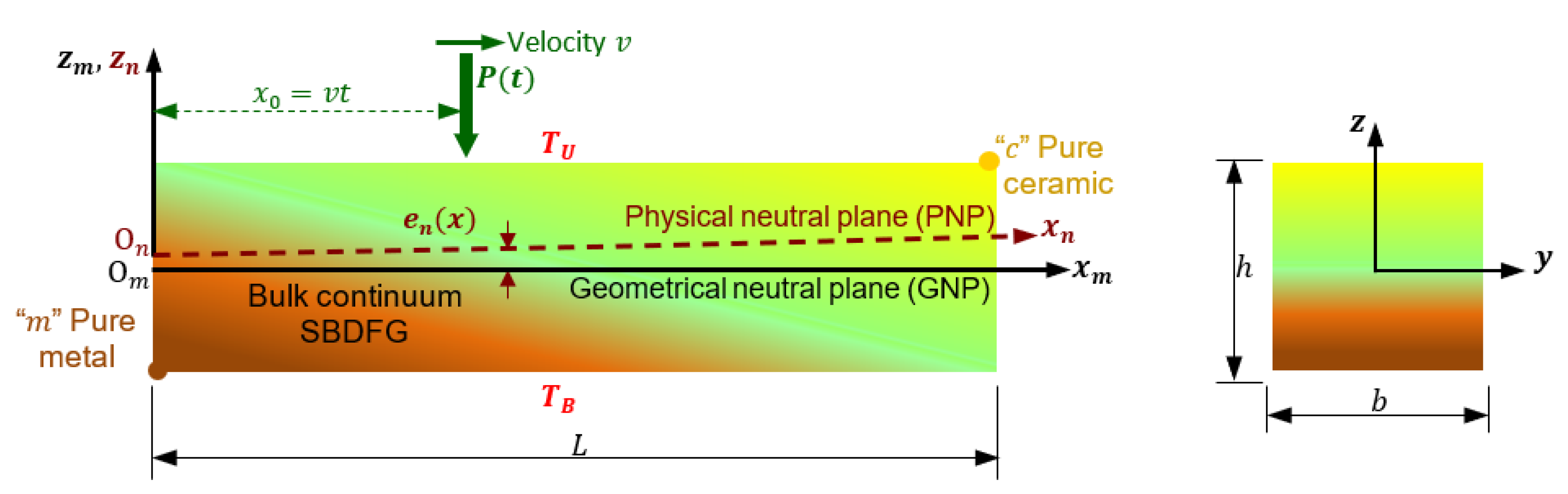
2.1. Material Constitutions and Distributions
2.2. Kinematics Relation
2.3. Constitutive Relations
3. Formulation of Governing Equations
3.1. Moving Load Formulations
3.2. Thermal Environment Formulations
- Linear temperature rise (LTR) for
- Nonlinear temperature rise (NTR) for
4. Analytical Solution
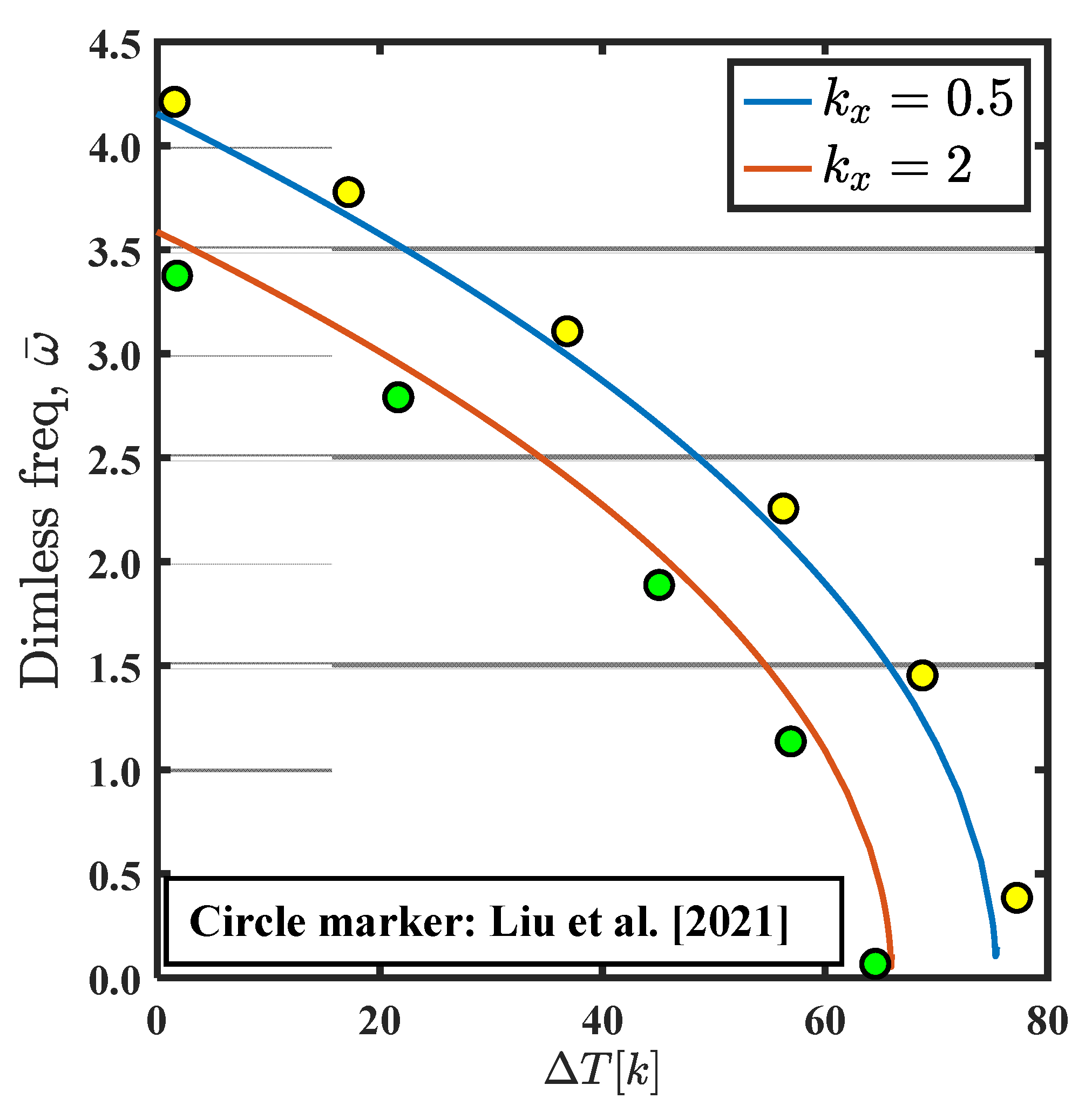
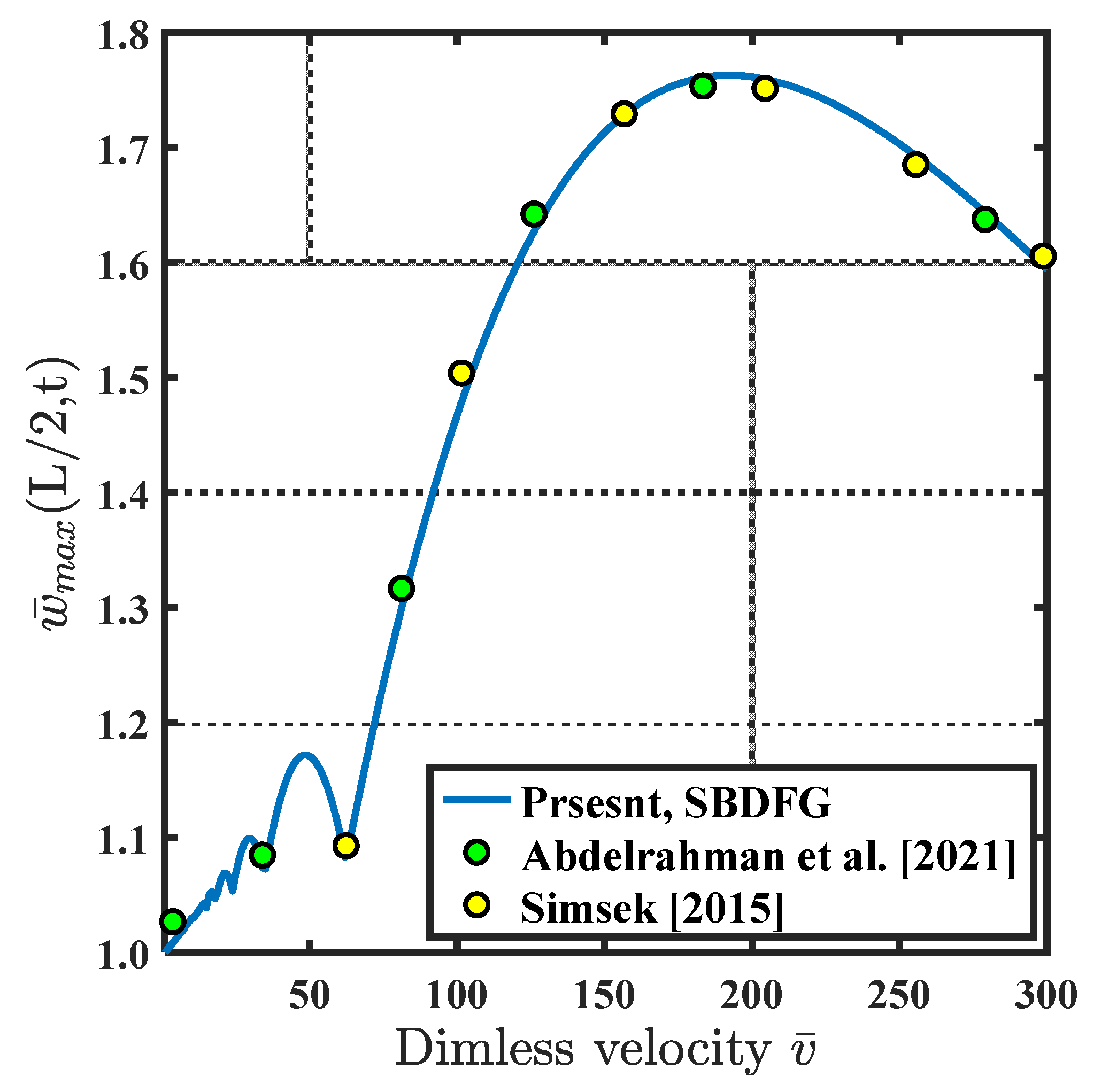
5. Model Validation
6. Numerical Results
6.1. Influence of the Gradation Indices
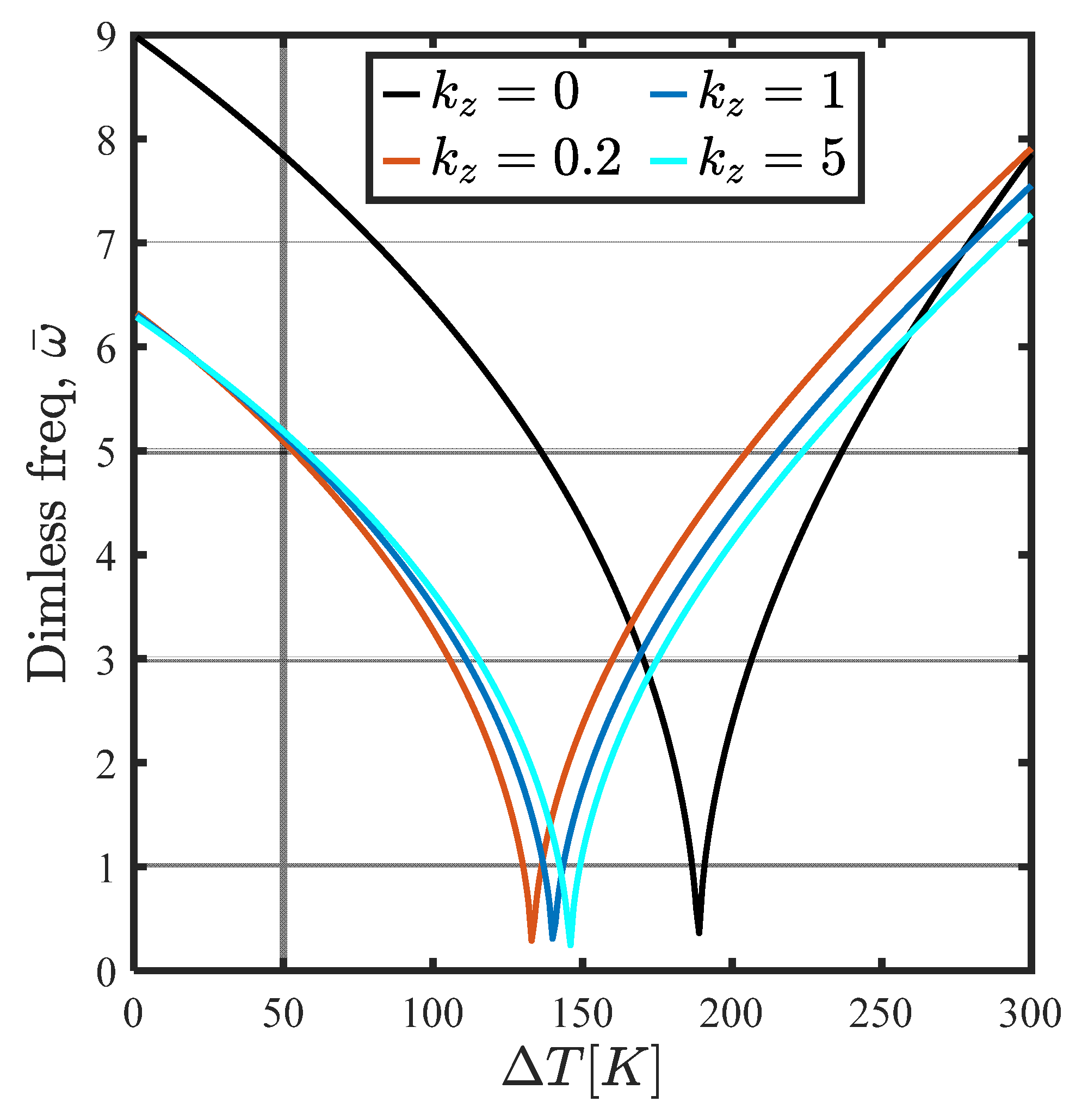
6.2. Influence of Temperature Distribution
6.3. Influence of the Moving Load Velocity
7. Conclusions
- ✓
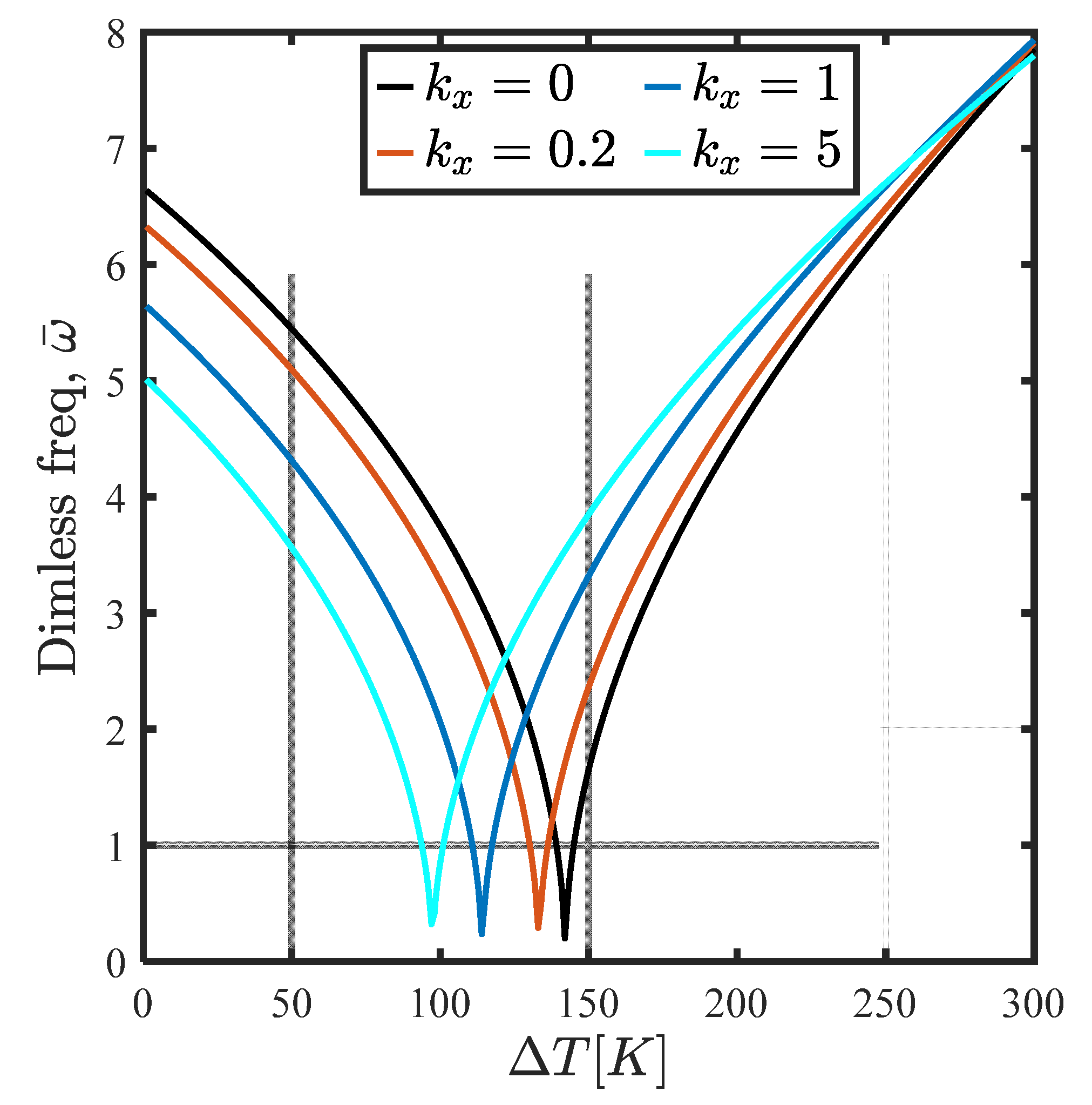
- Fundamental frequencies of SBDFG microbeams reduce with a rise in temperature until it reaches the critical frequency temperature. This is because the geometrical stiffness decreases when the temperature rises without any variation in equivalent mass.
- ✓
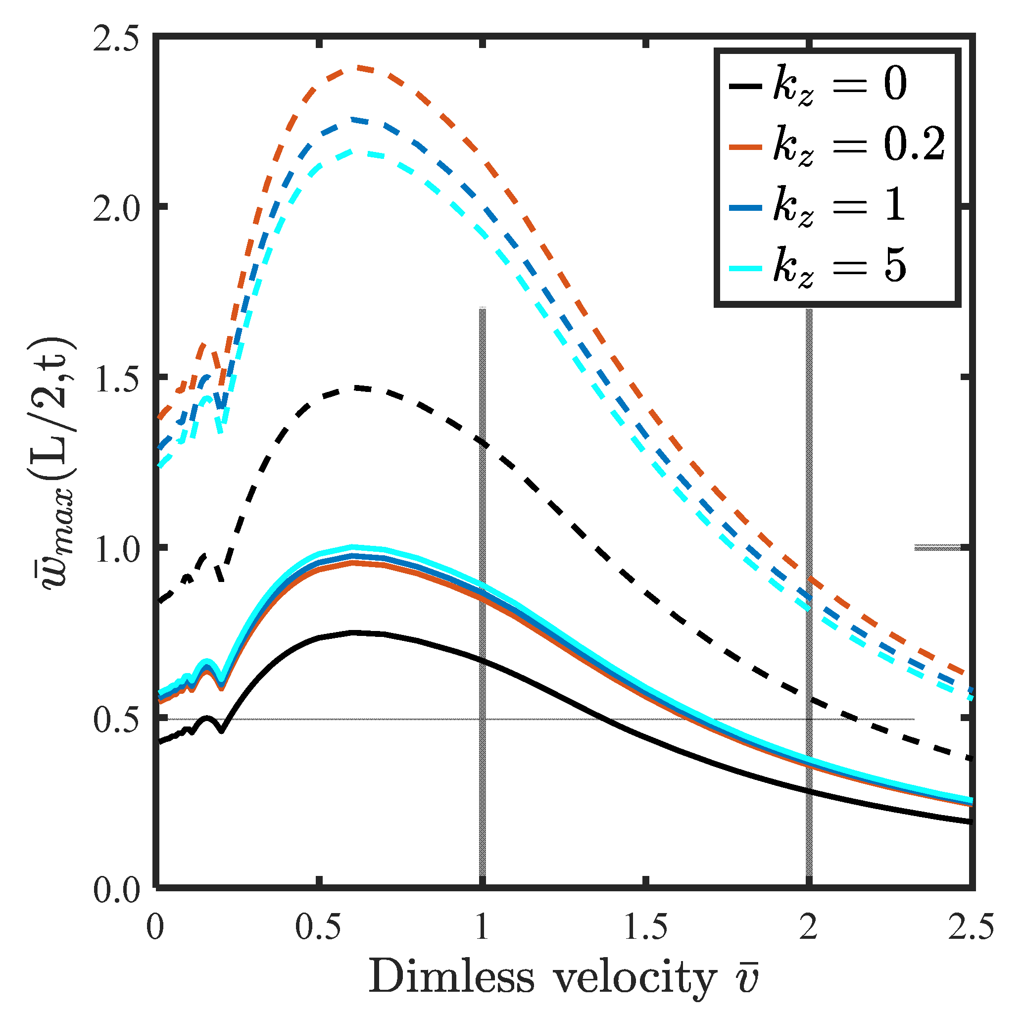
- By increasing the gradation index through the thickness, the dynamic deflection increases for temperature-independent material. However, in the case of temperature-dependent material, increasing in from 0 to 0.2, the dynamic deflection increased significantly, and after that, dynamic deflection reduced with the increasing gradation index
- ✓
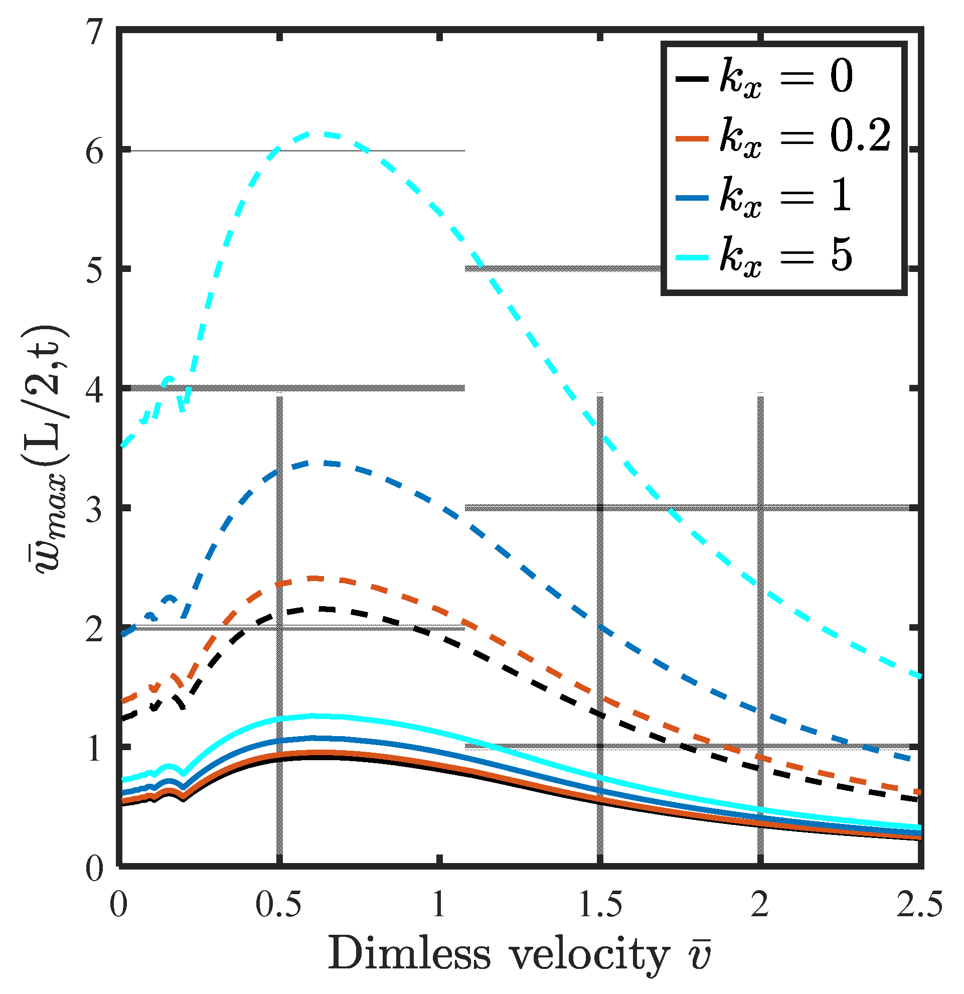
- The effect of gradation index in the axial direction on the dynamic deflection is increased significantly in the case of LTR relative to temperature-independent material.
- ✓
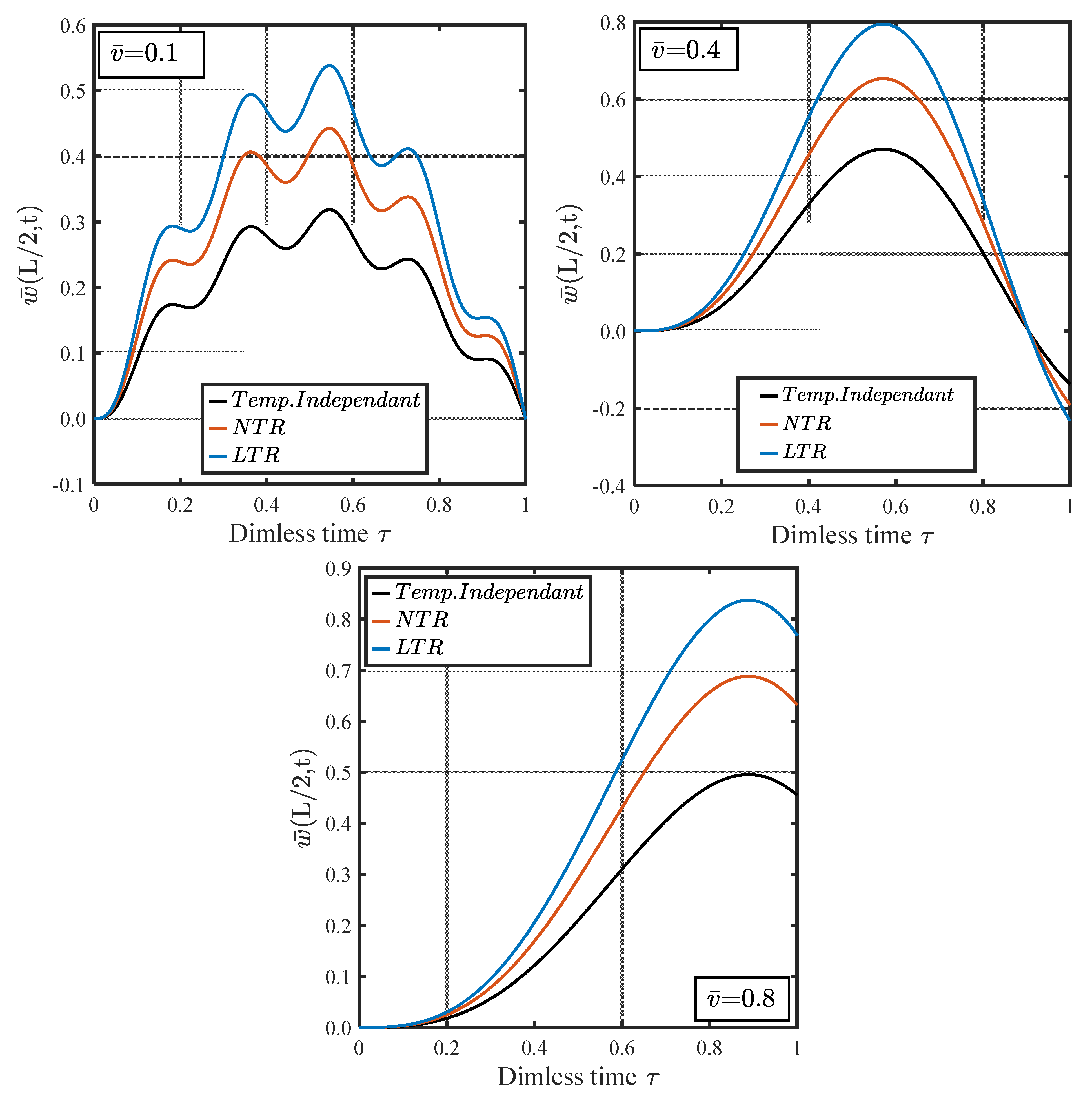
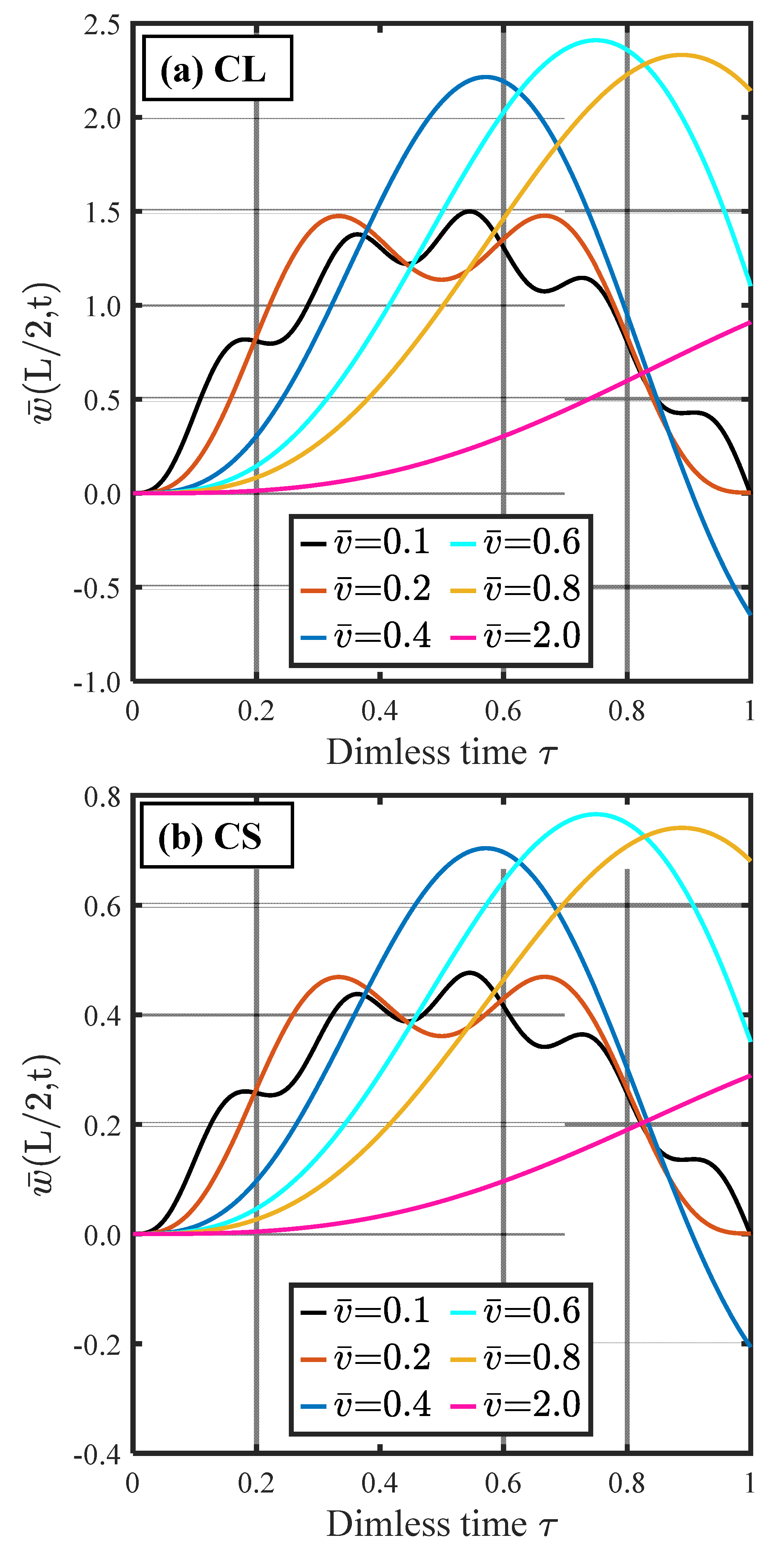
- The temperature for the LTR type is larger than that for both the NTR type and temperature-independent material. As seen, by increasing the velocity, the profile of dynamic deflection vs. time is changed completely from oscillatory to parabolic to exponential functions. Therefore, the dynamic deflection profile response is dependent on the velocity of the moving mass.
- ✓
- The shapes of the time history curves are strongly affected by the moving velocity. The number of vibration cycles of the microbeam is enlarged at low velocities of the moving load because the ratio of moving load velocity to critical velocity becomes low.
Author Contributions
Funding
Informed Consent Statement
Data Availability Statement
Acknowledgments
Conflicts of Interest
References
- Attia, M.A.; Shanab, R.A. Vibration characteristics of two-dimensional FGM nanobeams with couple stress and surface energy under general boundary conditions. Aerosp. Sci. Technol. 2021, 111, 106552. [Google Scholar] [CrossRef]
- Sayyad, A.S.; Ghugal, Y.M. Modeling and analysis of functionally graded sandwich beams: A review. Mech. Adv. Mater. Struct. 2019, 26, 1776–1795. [Google Scholar] [CrossRef]
- Zhao, S.; Zhang, Y.; Wu, H.; Zhang, Y.; Yang, J. Functionally graded graphene origami-enabled auxetic metamaterial beams with tunable buckling and postbuckling resistance. Eng. Struct. 2022, 268, 114763. [Google Scholar] [CrossRef]
- Xiao, S.; Cao, Y.; Wu, G.; Guo, Y.; Gao, G.; Chen, S.; Liu, P.; Wang, Z.; Li, P.; Yu, J.; et al. Influence of the distributed grounding layout for intercity trains on the ‘train-rail’ circumflux. IEEE Trans. Circuits Syst. II Express Briefs 2022. early access. [Google Scholar] [CrossRef]
- Melaibari, A.; Abdelrahman, A.A.; Hamed, M.A.; Abdalla, A.W.; Eltaher, M.A. Dynamic Analysis of a Piezoelectrically Layered Perforated Nonlocal Strain Gradient Nanobeam with Flexoelectricity. Mathematics 2022, 10, 2614. [Google Scholar] [CrossRef]
- Ahmadi, I. Vibration analysis of 2D-functionally graded nanobeams using the nonlocal theory and meshless method. Eng. Anal. Bound. Elem. 2021, 124, 142–154. [Google Scholar] [CrossRef]
- Eltaher, M.A.; Mohamed, N. Nonlinear stability and vibration of imperfect CNTs by doublet mechanics. Appl. Math. Comput. 2020, 382, 125311. [Google Scholar] [CrossRef]
- Asghari, M.; Rahaeifard, M.; Kahrobaiyan, M.H.; Ahmadian, M.T. The modified couple stress functionally graded Timoshenko beam formulation. Mater. Des. 2011, 32, 1435–1443. [Google Scholar] [CrossRef]
- Şimşek, M. Buckling of Timoshenko beams composed of two-dimensional functionally graded material (2D-FGM) having different boundary conditions. Compos. Struct. 2016, 149, 304–314. [Google Scholar] [CrossRef]
- Nejad, M.Z.; Hadi, A. Non-local analysis of free vibration of bi-directional functionally graded Euler–Bernoulli nano-beams. Int. J. Eng. Sci. 2016, 105, 1–11. [Google Scholar] [CrossRef]
- Nejad, M.Z.; Hadi, A.; Rastgoo, A. Buckling analysis of arbitrary two-directional functionally graded Euler–Bernoulli nano-beams based on nonlocal elasticity theory. Int. J. Eng. Sci. 2016, 103, 1–10. [Google Scholar] [CrossRef]
- Mirafzal, A.; Fereidoon, A. Dynamic characteristics of temperature-dependent viscoelastic FG nanobeams subjected to 2D-magnetic field under periodic loading. Appl. Phys. A 2017, 123, 247. [Google Scholar] [CrossRef]
- Shafiei, N.; Kazemi, M. Buckling analysis on the bi-dimensional functionally graded porous tapered nano-/micro-scale beams. Aerosp. Sci. Technol. 2017, 66, 1–11. [Google Scholar] [CrossRef]
- Shafiei, N.; Mirjavadi, S.S.; MohaselAfshari, B.; Rabby, S.; Kazemi, M. Vibration of two-dimensional imperfect functionally graded (2D-FG) porous nano-/micro-beams. Comput. Methods Appl. Mech. Eng. 2017, 322, 615–632. [Google Scholar] [CrossRef]
- Rajasekaran, S.; Khaniki, H.B. Free vibration analysis of bi-directional functionally graded single/multi-cracked beams. Int. J. Mech. Sci. 2018, 144, 341–356. [Google Scholar] [CrossRef]
- Sahmani, S.; Safaei, B. Nonlinear free vibrations of bi-directional functionally graded micro/nano-beams including nonlocal stress and microstructural strain gradient size effects. Thin-Walled Struct. 2019, 140, 342–356. [Google Scholar] [CrossRef]
- Sahmani, S.; Safaei, B. Nonlocal strain gradient nonlinear resonance of bi-directional functionally graded composite micro/nano-beams under periodic soft excitation. Thin-Walled Struct. 2019, 143, 106226. [Google Scholar] [CrossRef]
- Tang, Y.; Ding, Q. Nonlinear vibration analysis of a bi-directional functionally graded beam under hygro-thermal loads. Compos. Struct. 2019, 225, 111076. [Google Scholar] [CrossRef]
- Tang, Y.; Lv, X.; Yang, T. Bi-directional functionally graded beams: Asymmetric modes and nonlinear free vibration. Compos. Part B Eng. 2019, 156, 319–331. [Google Scholar] [CrossRef]
- Attia, M.A.; Mohamed, S.A. Thermal vibration characteristics of pre/post-buckled bi-directional functionally graded tapered microbeams based on modified couple stress Reddy beam theory. Eng. Comput. 2020, 38, 2079–2105. [Google Scholar] [CrossRef]
- Barati, A.; Hadi, A.; Nejad, M.Z.; Noroozi, R. On vibration of bi-directional functionally graded nanobeams under magnetic field. Mech. Based Des. Struct. Mach. 2020, 50, 468–485. [Google Scholar] [CrossRef]
- Ghatage, P.S.; Kar, V.R.; Sudhagar, P.E. On the numerical modelling and analysis of multi-directional functionally graded composite structures: A review. Compos. Struct. 2020, 236, 111837. [Google Scholar] [CrossRef]
- Karami, B.; Janghorban, M.; Rabczuk, T. Dynamics of two-dimensional functionally graded tapered Timoshenko nanobeam in thermal environment using nonlocal strain gradient theory. Compos. Part B Eng. 2020, 182, 107622. [Google Scholar] [CrossRef]
- Guo, L.; Zhao, S.; Guo, Y.; Yang, J.; Kitipornchai, S. Bandgaps in functionally graded phononic crystals containing graphene origami-enabled metamaterials. Int. J. Mech. Sci. 2022, 240, 107956. [Google Scholar] [CrossRef]
- Zhao, S.; Zhang, Y.; Zhang, Y.; Zhang, W.; Yang, J.; Kitipornchai, S. Data-driven modeling for thermo-elastic properties of vacancy-defective graphene reinforced nanocomposites with its application to functionally graded beams. Eng. Comput. 2022, 1–17. [Google Scholar] [CrossRef]
- Daikh, A.A.; Houari MS, A.; Eltaher, M.A. A novel nonlocal strain gradient Quasi-3D bending analysis of sigmoid functionally graded sandwich nanoplates. Compos. Struct. 2021, 262, 113347. [Google Scholar] [CrossRef]
- Daikh, A.A.; Houari MS, A.; Belarbi, M.O.; Chakraverty, S.; Eltaher, M.A. Analysis of axially temperature-dependent functionally graded carbon nanotube reinforced composite plates. Eng. Comput. 2021, 38, 2533–2554. [Google Scholar] [CrossRef]
- Soni, S.K.; Thomas, B.; Swain, A.; Roy, T. Functionally graded carbon nanotubes reinforced composite structures: An extensive review. Compos. Struct. 2022, 299, 116075. [Google Scholar] [CrossRef]
- Attia, M.A.; Shanab, R.A. On the dynamic response of bi-directional functionally graded nanobeams under moving harmonic load accounting for surface effect. Acta Mech. 2022, 233, 3291–3317. [Google Scholar] [CrossRef]
- Zhao, S.; Zhao, Z.; Yang, Z.; Ke, L.; Kitipornchai, S.; Yang, J. Functionally graded graphene reinforced composite structures: A review. Eng. Struct. 2020, 210, 110339. [Google Scholar] [CrossRef]
- Assie, A.E.; Mohamed, S.M.; Shanab, R.A.; Abo-bakr, R.M.; Eltaher, M.A. Static Buckling of 2D FG Porous Plates Resting on Elastic Foundation based on Unified Shear Theories. J. Appl. Comput. Mech. 2023, 9, 239–258. [Google Scholar] [CrossRef]
- Eglin, M.; Eriksson, M.A.; Carpick, R.W. Microparticle manipulation using inertial forces. Appl. Phys. Lett. 2006, 88, 091913. [Google Scholar] [CrossRef] [Green Version]
- Roudbari, M.A.; Jorshari, T.D.; Arani, A.G.; Lü, C.; Rabczuk, T. Transient responses of two mutually interacting single-walled boron nitride nanotubes induced by a moving nanoparticle. Eur. J. Mech.-A/Solids 2020, 82, 103978. [Google Scholar] [CrossRef]
- Abdelrahman, A.A.; Ashry, M.; Alshorbagy, A.E.; Abdallah, W.S. On the mechanical behavior of two directional symmetrical functionally graded beams under moving load. Int. J. Mech. Mater. Des. 2021, 17, 563–586. [Google Scholar] [CrossRef]
- Şimşek, M.; Kocatürk, T. Free and forced vibration of a functionally graded beam subjected to a concentrated moving harmonic load. Compos. Struct. 2009, 90, 465–473. [Google Scholar] [CrossRef]
- Şimşek, M. Bi-directional functionally graded materials (BDFGMs) for free and forced vibration of Timoshenko beams with various boundary conditions. Compos. Struct. 2015, 133, 968–978. [Google Scholar] [CrossRef]
- Hosseini SA, H.; Rahmani, O. Exact solution for axial and transverse dynamic response of functionally graded nanobeam under moving constant load based on nonlocal elasticity theory. Meccanica 2017, 52, 1441–1457. [Google Scholar] [CrossRef]
- Ghadiri, M.; Rajabpour, A.; Akbarshahi, A. Non-linear forced vibration analysis of nanobeams subjected to moving concentrated load resting on a viscoelastic foundation considering thermal and surface effects. Appl. Math. Model. 2017, 50, 676–694. [Google Scholar] [CrossRef]
- Barati, M.R.; Shahverdi, H. Small-scale effects on the dynamic response of inhomogeneous nanobeams on elastic substrate under uniform dynamic load. Eur. Phys. J. Plus 2017, 132, 167. [Google Scholar] [CrossRef]
- Zhang, Q.; Liu, H. On the dynamic response of porous functionally graded microbeam under moving load. Int. J. Eng. Sci. 2020, 153, 103317. [Google Scholar] [CrossRef]
- Liu, H.; Zhang, Q.; Ma, J. Thermo-mechanical dynamics of two-dimensional FG microbeam subjected to a moving harmonic load. Acta Astronaut. 2021, 178, 681–692. [Google Scholar] [CrossRef]
- Hosseini, S.A.; Rahmani, O.; Bayat, S. Thermal effect on forced vibration analysis of FG nanobeam subjected to moving load by Laplace transform method. Mech. Based Des. Struct. Mach. 2021, 1–20. [Google Scholar] [CrossRef]
- Abdelrahman, A.A.; Esen, I.; Daikh, A.A.; Eltaher, M.A. Dynamic analysis of FG nanobeam reinforced by carbon nanotubes and resting on elastic foundation under moving load. Mech. Based Des. Struct. Mach. 2021, 1–24. [Google Scholar] [CrossRef]
- Abdelrahman, A.A.; Esen, I.; Özarpa, C.; Eltaher, M.A. Dynamics of perforated nanobeams subject to moving mass using the nonlocal strain gradient theory. Appl. Math. Model. 2021, 96, 215–235. [Google Scholar] [CrossRef]
- Abdelrahman, A.A.; Esen, I.; Ozarpa, C.; Shaltout, R.; Eltaher, M.A.; Assie, A.E. Dynamics of perforated higher order nanobeams subject to moving load using the nonlocal strain gradient theory. Smart Struct. Syst. 2021, 28, 515–533. [Google Scholar] [CrossRef]
- Chung, K.L.; Tian, H.; Wang, S.; Feng, B.; Lai, G. Miniaturization of microwave planar circuits using composite microstrip/coplanar-waveguide transmission lines. Alex. Eng. J. 2022, 61, 8933–8942. [Google Scholar] [CrossRef]
- Eltaher, M.A.; Abdelrahman, A.A.; Esen, I. Dynamic analysis of nanoscale Timoshenko CNTs based on doublet mechanics under moving load. Eur. Phys. J. Plus 2021, 136, 705. [Google Scholar] [CrossRef]
- Esen, I.; Abdelrahman, A.A.; Eltaher, M.A. On vibration of sigmoid/symmetric functionally graded nonlocal strain gradient nanobeams under moving load. Int. J. Mech. Mater. Des. 2021, 17, 721–742. [Google Scholar] [CrossRef]
- Esen, I.; Eltaher, M.A.; Abdelrahman, A.A. Vibration response of symmetric and sigmoid functionally graded beam rested on elastic foundation under moving point mass. Mech. Based Des. Struct. Mach. 2021, 1–25. [Google Scholar] [CrossRef]
- Thongchom, C.; Roodgar Saffari, P.; Roudgar Saffari, P.; Refahati, N.; Sirimontree, S.; Keawsawasvong, S.; Titotto, S. Dynamic response of fluid-conveying hybrid smart carbon nanotubes considering slip boundary conditions under a moving nanoparticle. Mech. Adv. Mater. Struct. 2022, 1–14. [Google Scholar] [CrossRef]
- Akbaş, Ş.D.; Ersoy, H.; Akgöz, B.; Civalek, Ö. Dynamic analysis of a fiber-reinforced composite beam under a moving load by the Ritz method. Mathematics 2021, 9, 1048. [Google Scholar] [CrossRef]
- Rajasekaran, S.; Khaniki, H.B. Size-dependent forced vibration of non-uniform bi-directional functionally graded beams embedded in variable elastic environment carrying a moving harmonic mass. Appl. Math. Model. 2019, 72, 129–154. [Google Scholar] [CrossRef]
- Attia, M.A.; Mahmoud, F.F. Modeling and analysis of nanobeams based on nonlocal-couple stress elasticity and surface energy theories. Int. J. Mech. Sci. 2016, 105, 126–134. [Google Scholar] [CrossRef]
- Attia, M.A. On the mechanics of functionally graded nanobeams with the account of surface elasticity. Int. J. Eng. Sci. 2017, 115, 73–101. [Google Scholar] [CrossRef]
- Yang, T.; Tang, Y.; Li, Q.; Yang, X.D. Nonlinear bending, buckling and vibration of bi-directional functionally graded nanobeams. Compos. Struct. 2018, 204, 313–319. [Google Scholar] [CrossRef]
- Reddy, J.N.; Chin, C.D. Thermomechanical analysis of functionally graded cylinders and plates. J. Therm. Stress. 1998, 21, 593–626. [Google Scholar] [CrossRef]
- Naghavi, M.; Sarrami-Foroushani, S.; Azhari, F. Bending analysis of functionally graded sandwich plates using the refined finite strip method. J. Sandw. Struct. Mater. 2022, 24, 448–483. [Google Scholar] [CrossRef]
- Nguyen, T.H.; Niiranen, J. Nonlocal continuum damage modeling for functionally graded plates of third-order shear deformation theory. Thin-Walled Struct. 2021, 164, 107876. [Google Scholar] [CrossRef]
- Abo-bakr, R.M.; Shanab, R.A.; Attia, M.A. Multi-objective optimization for lightweight design of bi-directional functionally graded beams for maximum frequency and buckling load. Compos. Struct. 2021, 278, 114691. [Google Scholar] [CrossRef]
- Gholami, R.; Ansari, R. Nonlinear resonance responses of geometrically imperfect shear deformable nanobeams including surface stress effects. Int. J. Non-Linear Mech. 2017, 97, 115–125. [Google Scholar] [CrossRef]
- Reddy, J.N. A simple higher-order theory for laminated composite plates. ASME J. Appl. Mech. 1984, 51, 745–752. [Google Scholar] [CrossRef]
- Kong, S. A review on the size-dependent models of micro-beam and micro-plate based on the modified couple stress theory. Arch. Comput. Methods Eng. 2022, 29, 1–31. [Google Scholar] [CrossRef]
- Al-Basyouni, K.S.; Tounsi, A.; Mahmoud, S.R. Size dependent bending and vibration analysis of functionally graded micro beams based on modified couple stress theory and neutral surface position. Compos. Struct. 2015, 125, 621–630. [Google Scholar] [CrossRef]
- He, X.T.; Zhang, M.Q.; Pang, B.; Sun, J.Y. Solution of the Thermoelastic Problem for a Two-Dimensional Curved Beam with Bimodular Effects. Mathematics 2022, 10, 3002. [Google Scholar] [CrossRef]
- Attia, M.A.; Mohamed, S.A. Nonlinear thermal buckling and postbuckling analysis of bidirectional functionally graded tapered microbeams based on Reddy beam theory. Eng. Comput. 2022, 38, 525–554. [Google Scholar] [CrossRef]
- Yang, F.A.C.M.; Chong, A.C.M.; Lam, D.C.C.; Tong, P. Couple stress based strain gradient theory for elasticity. Int. J. Solids Struct. 2002, 39, 2731–2743. [Google Scholar] [CrossRef]
- Park, S.K.; Gao, X.L. Bernoulli–Euler beam model based on a modified couple stress theory. J. Micromech. Microeng. 2006, 16, 2355. [Google Scholar] [CrossRef]
- Li, Z.; He, Y.; Lei, J.; Guo, S.; Liu, D.; Wang, L. A standard experimental method for determining the material length scale based on modified couple stress theory. Int. J. Mech. Sci. 2018, 141, 198–205. [Google Scholar] [CrossRef]
- Nguyen, D.K.; Nguyen, Q.H.; Tran, T.T.; Bui, V.T. Vibration of bi-dimensional functionally graded Timoshenko beams excited by a moving load. Acta Mech. 2017, 228, 141–155. [Google Scholar] [CrossRef]
- Songsuwan, W.; Pimsarn, M.; Wattanasakulpong, N. Dynamic responses of functionally graded sandwich beams resting on elastic foundation under harmonic moving loads. Int. J. Struct. Stab. Dyn. 2018, 18, 1850112. [Google Scholar] [CrossRef]
- Ebrahimi, F.; Salari, E. Thermal buckling and free vibration analysis of size dependent Timoshenko FG nanobeams in thermal environments. Compos. Struct. 2015, 128, 363–380. [Google Scholar] [CrossRef]
- Dehrouyeh-Semnani, A.M.; Mostafaei, H.; Dehrouyeh, M.; Nikkhah-Bahrami, M. Thermal pre-and post-snap-through buckling of a geometrically imperfect doubly-clamped microbeam made of temperature-dependent functionally graded materials. Compos. Struct. 2017, 170, 122–134. [Google Scholar] [CrossRef]
- Olsson, M. On the fundamental moving load problem. J. Sound Vib. 1991, 145, 299–307. [Google Scholar] [CrossRef]
- Dimitrovová, Z.; Varandas, J.N. Critical velocity of a load moving on a beam with a sudden change of foundation stiffness: Applications to high-speed trains. Comput. Struct. 2009, 87, 1224–1232. [Google Scholar] [CrossRef]


| Source | Pure SUS304 | kz = 1.0 | Pure Al2O3 | |
|---|---|---|---|---|
| Present, SBDFG | 1.7475 | 1.2641 | 0.9433 | |
| Ref. [29] (RBT) | 1.7384 | 1.2575 | 0.9384 | |
| Ref. [70] (TBT) | 1.7379 | 1.2287 | 0.9382 | |
| Ref. [69] (TBT) | 1.7420 | 1.2566 | 0.9380 | |
| Ref. [35] (EBT) | 1.7324 | 1.2503 | 0.9328 | |
| vp | Present, SBDFG | 130 | 177 | 249 |
| Ref. [29] (RBT) | 131 | 178 | 252 | |
| Ref. [70] (TBT) | 132 | 179 | 252 | |
| Ref. [69] (TBT) | 131 | 178 | 251 | |
| Ref. [35] (EBT) | 132 | 179 | 252 |
| Material | Properties | |||||
|---|---|---|---|---|---|---|
| SUS304 (Metal) | 0 | 201.04 × 10⁹ | 3.079 × 10⁻⁴ | −6.534 × 10⁻⁷ | 0 | |
| 0 | 8166 | 0 | 0 | 0 | ||
| 0 | 0.3262 | 0 | 0 | 0 | ||
| 0 | 12.330 × 10⁻⁶ | 8.086 × 10⁻⁴ | 0 | 0 | ||
| Si3N4 (Ceramic) | 0 | 348.43 × 10⁹ | −3.070 × 10⁻⁴ | 2.160 × 10⁻⁷ | −8.946 × 10⁻¹¹ | |
| 0 | 2170 | 0 | 0 | 0 | ||
| 0 | 0.24 | 0 | 0 | 0 | ||
| 0 | 5.8723 × 10⁻⁶ | 9.095 × 10⁻⁴ | 0 | 0 |
| Source | ΔT | kz = 0.0 | kz = 1.0 |
|---|---|---|---|
| Present, SBDFG | 10 | 9.7643 | 5.7294 |
| Ref. [71] (TBT) | 9.6461 | 5.7717 | |
| Present, SBDFG | 30 | 9.6074 | 5.5964 |
| Ref. [71] (TBT) | 9.4538 | 5.6105 | |
| Present, SBDFG | 60 | 9.3682 | 5.3889 |
| Ref. [71] (TBT) | 9.1475 | 5.3537 |
Publisher’s Note: MDPI stays neutral with regard to jurisdictional claims in published maps and institutional affiliations. |
© 2022 by the authors. Licensee MDPI, Basel, Switzerland. This article is an open access article distributed under the terms and conditions of the Creative Commons Attribution (CC BY) license (https://creativecommons.org/licenses/by/4.0/).
Share and Cite
Attia, M.A.; Melaibari, A.; Shanab, R.A.; Eltaher, M.A. Dynamic Analysis of Sigmoid Bidirectional FG Microbeams under Moving Load and Thermal Load: Analytical Laplace Solution. Mathematics 2022, 10, 4797. https://doi.org/10.3390/math10244797
Attia MA, Melaibari A, Shanab RA, Eltaher MA. Dynamic Analysis of Sigmoid Bidirectional FG Microbeams under Moving Load and Thermal Load: Analytical Laplace Solution. Mathematics. 2022; 10(24):4797. https://doi.org/10.3390/math10244797
Chicago/Turabian StyleAttia, Mohamed A., Ammar Melaibari, Rabab A. Shanab, and Mohamed A. Eltaher. 2022. "Dynamic Analysis of Sigmoid Bidirectional FG Microbeams under Moving Load and Thermal Load: Analytical Laplace Solution" Mathematics 10, no. 24: 4797. https://doi.org/10.3390/math10244797