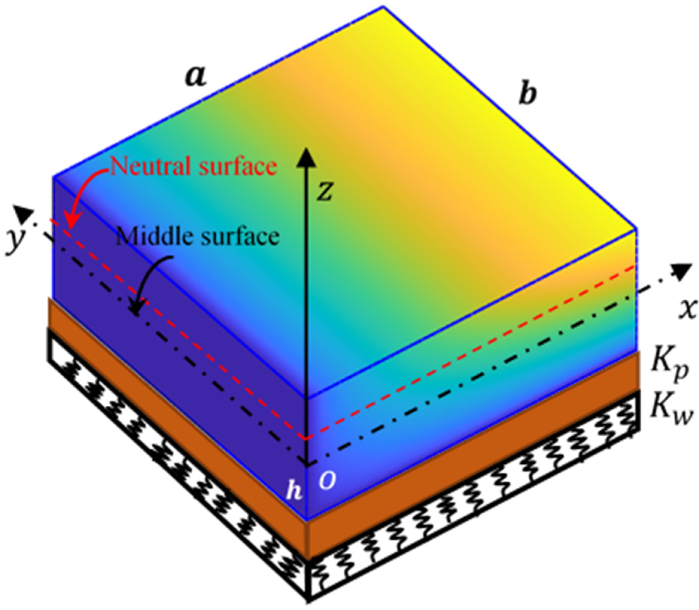
Figure 1.
Schematic diagram of BDFG plate geometry with Winkler–Pasternak foundations.
Figure 1.
Schematic diagram of BDFG plate geometry with Winkler–Pasternak foundations.
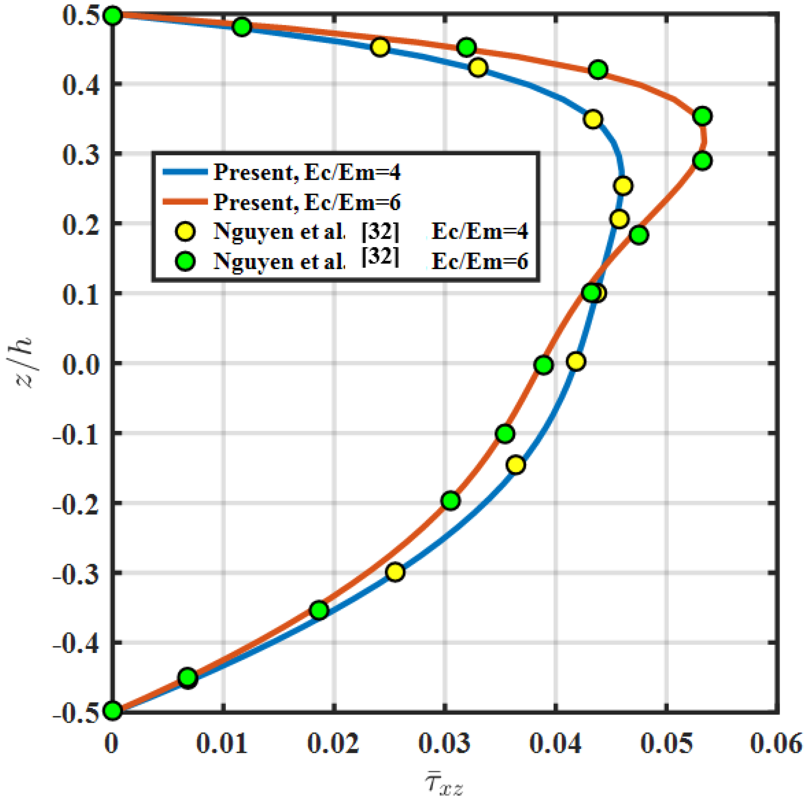
Figure 2.
Non-dimensional stress () at different Young’s modulus of ceramic and metal, at (a/h = 10).
Figure 2.
Non-dimensional stress () at different Young’s modulus of ceramic and metal, at (a/h = 10).
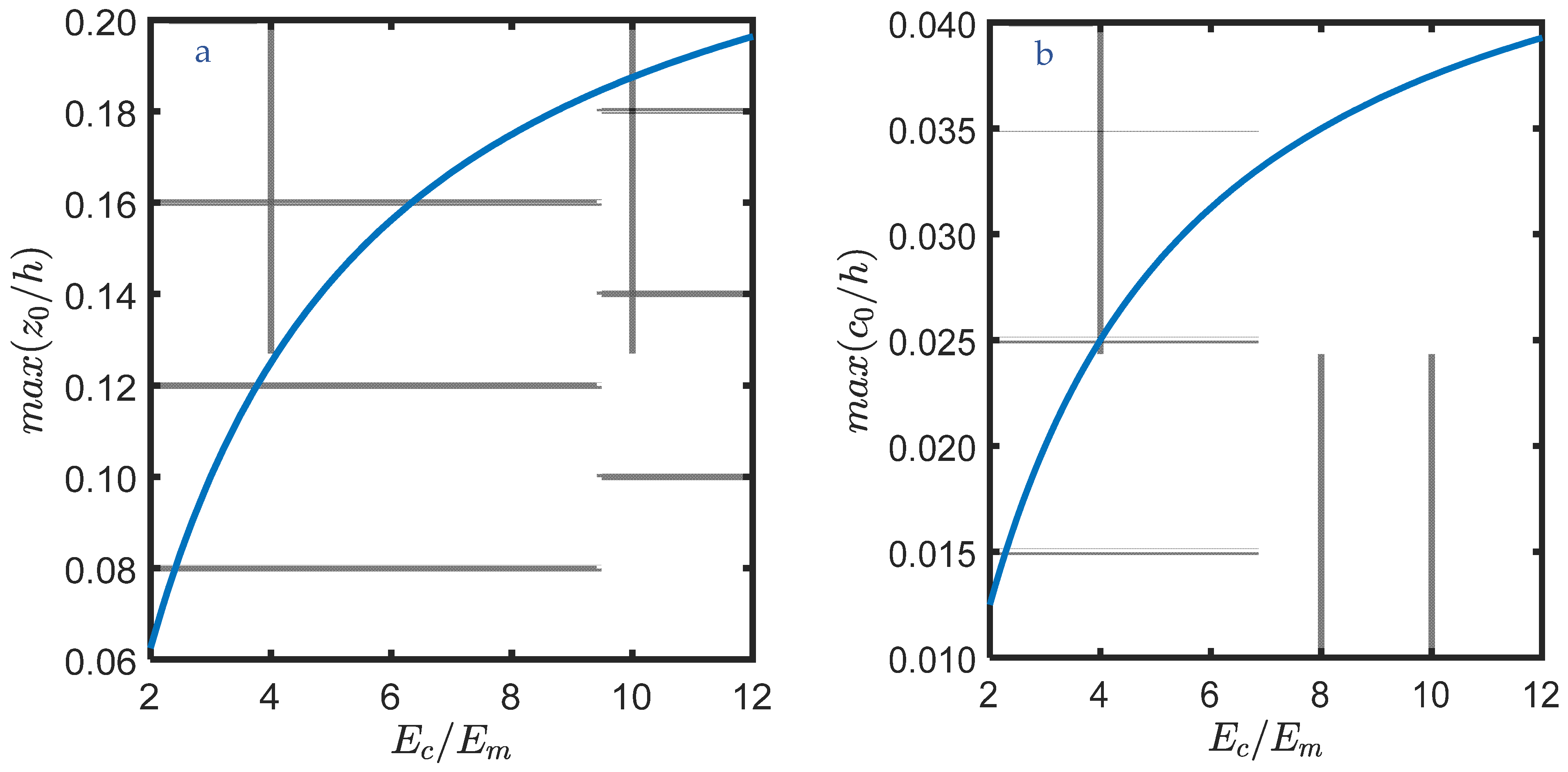
Figure 3.
Maximum values of (a) and (b) at different ratios at .
Figure 3.
Maximum values of (a) and (b) at different ratios at .
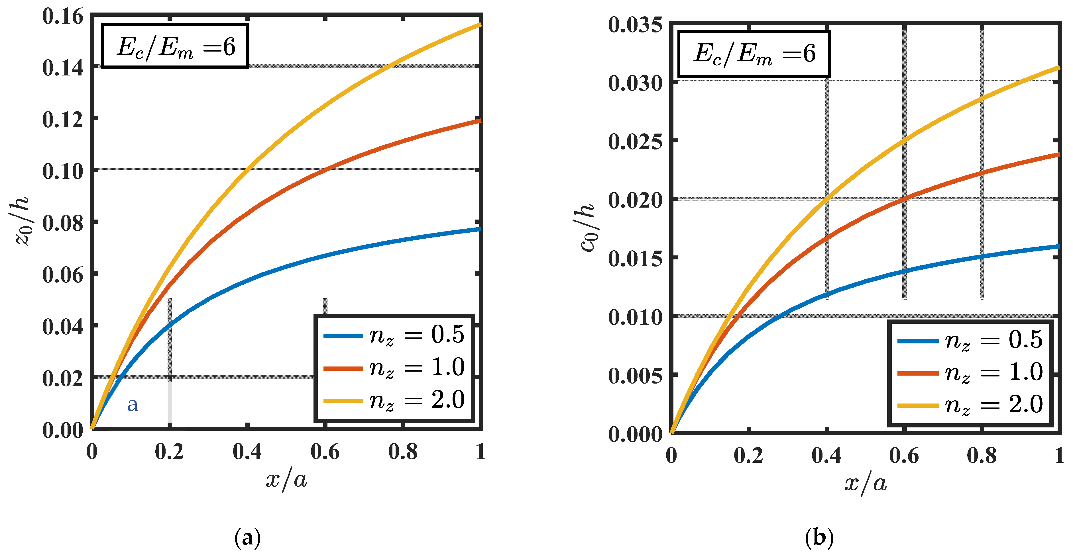
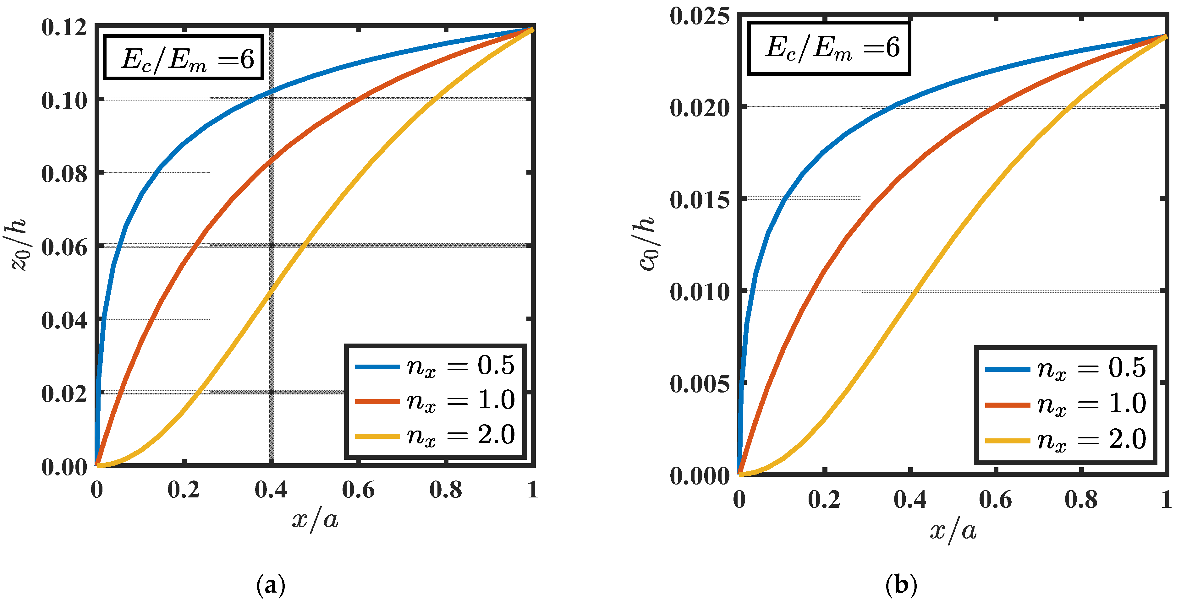
Figure 4.
Neutral axis paramaters and at different and young’s modulus of ceramic and metal, = 6 at (a) for and (b) for .
Figure 4.
Neutral axis paramaters and at different and young’s modulus of ceramic and metal, = 6 at (a) for and (b) for .
Figure 5.
Neutral axis paramaters and at different and young’s modulus of ceramic and metal, = 6 at (a) for and (b) for .
Figure 5.
Neutral axis paramaters and at different and young’s modulus of ceramic and metal, = 6 at (a) for and (b) for .
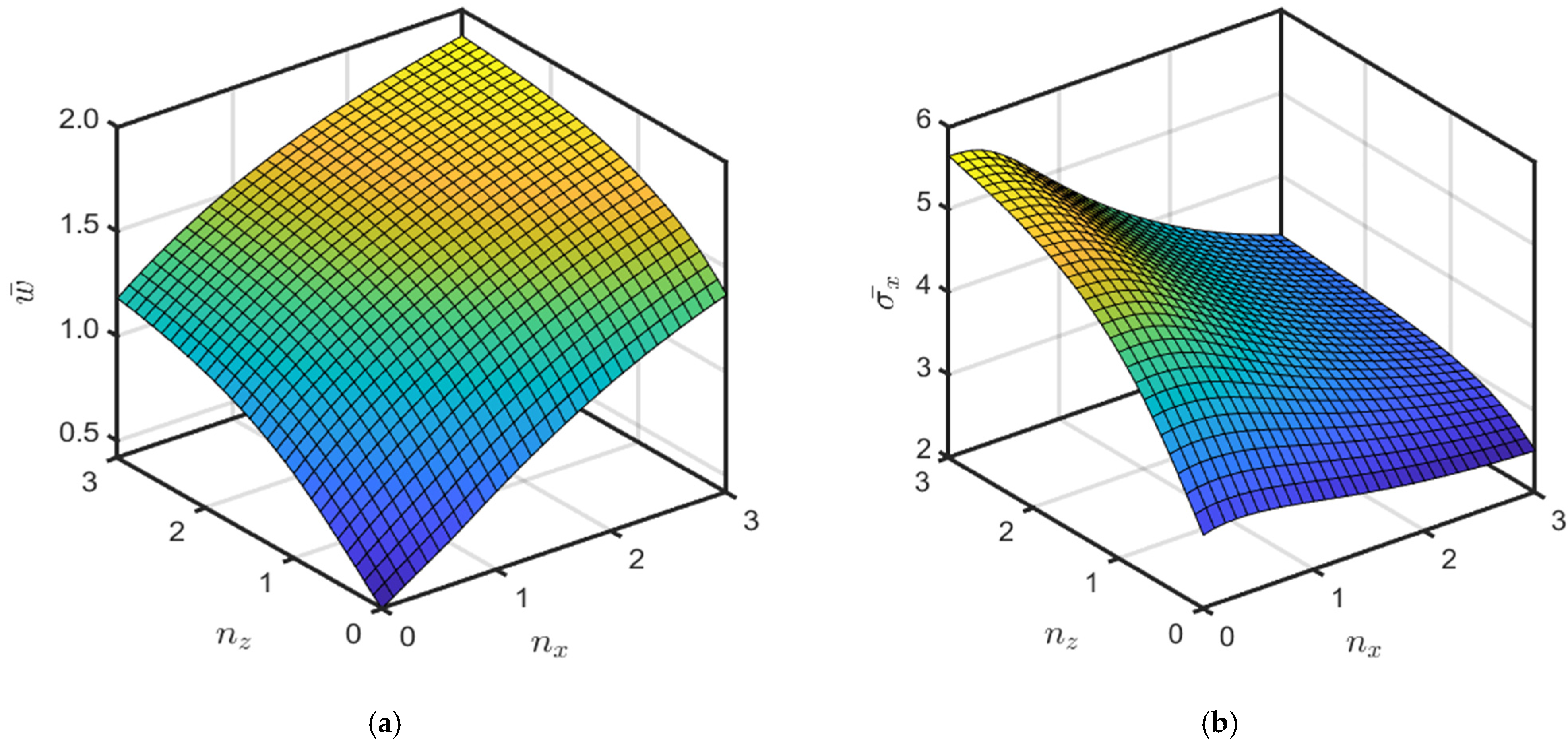
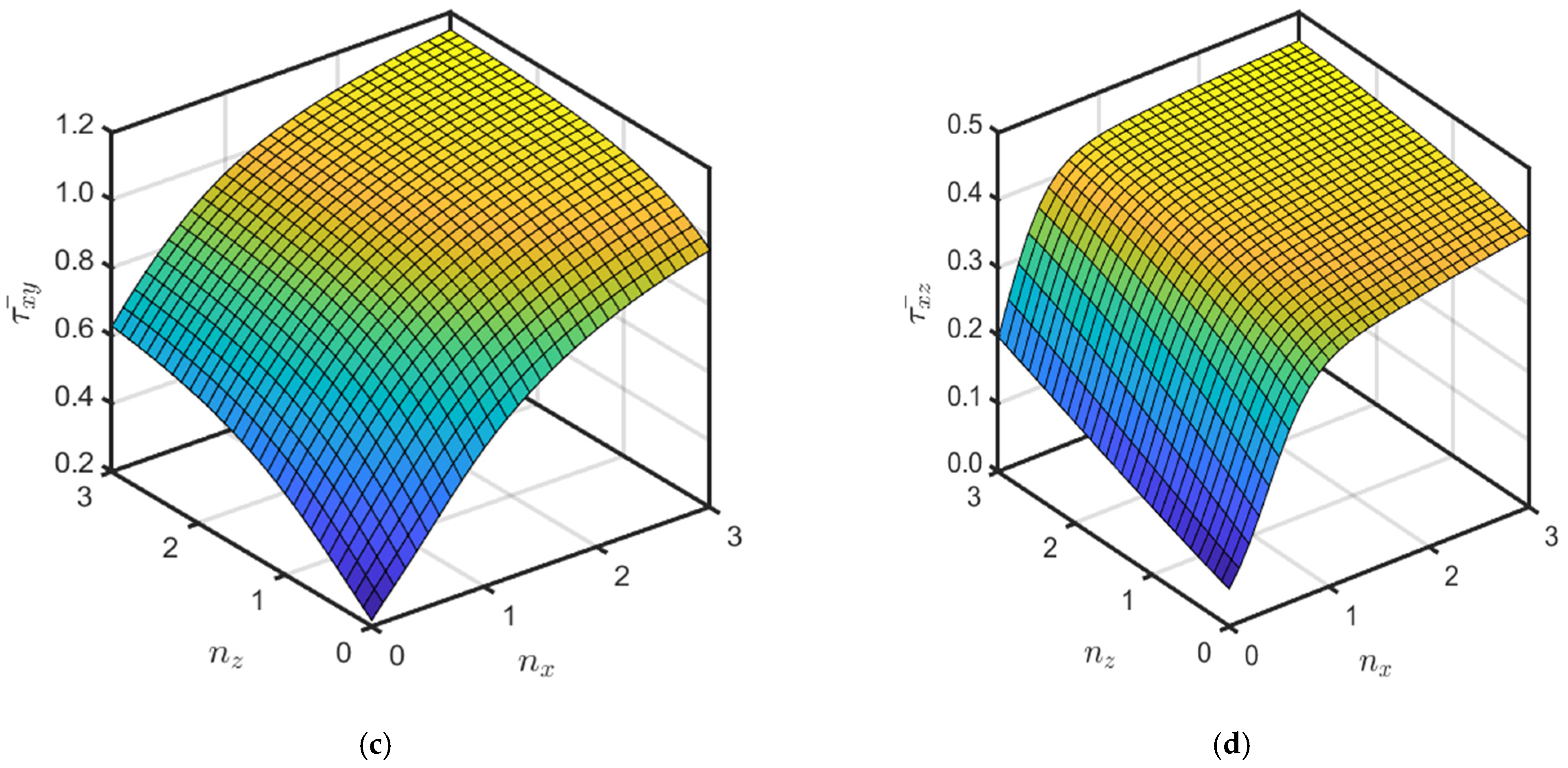
Figure 6.
Effect of gradation indices on the non-dimensional maximum deflection and stresses of BDFG under sinusoidal load . (a) Maximum deflection. (b) Normal stress . (c) Shear stress . (d) Shear stress .
Figure 6.
Effect of gradation indices on the non-dimensional maximum deflection and stresses of BDFG under sinusoidal load . (a) Maximum deflection. (b) Normal stress . (c) Shear stress . (d) Shear stress .
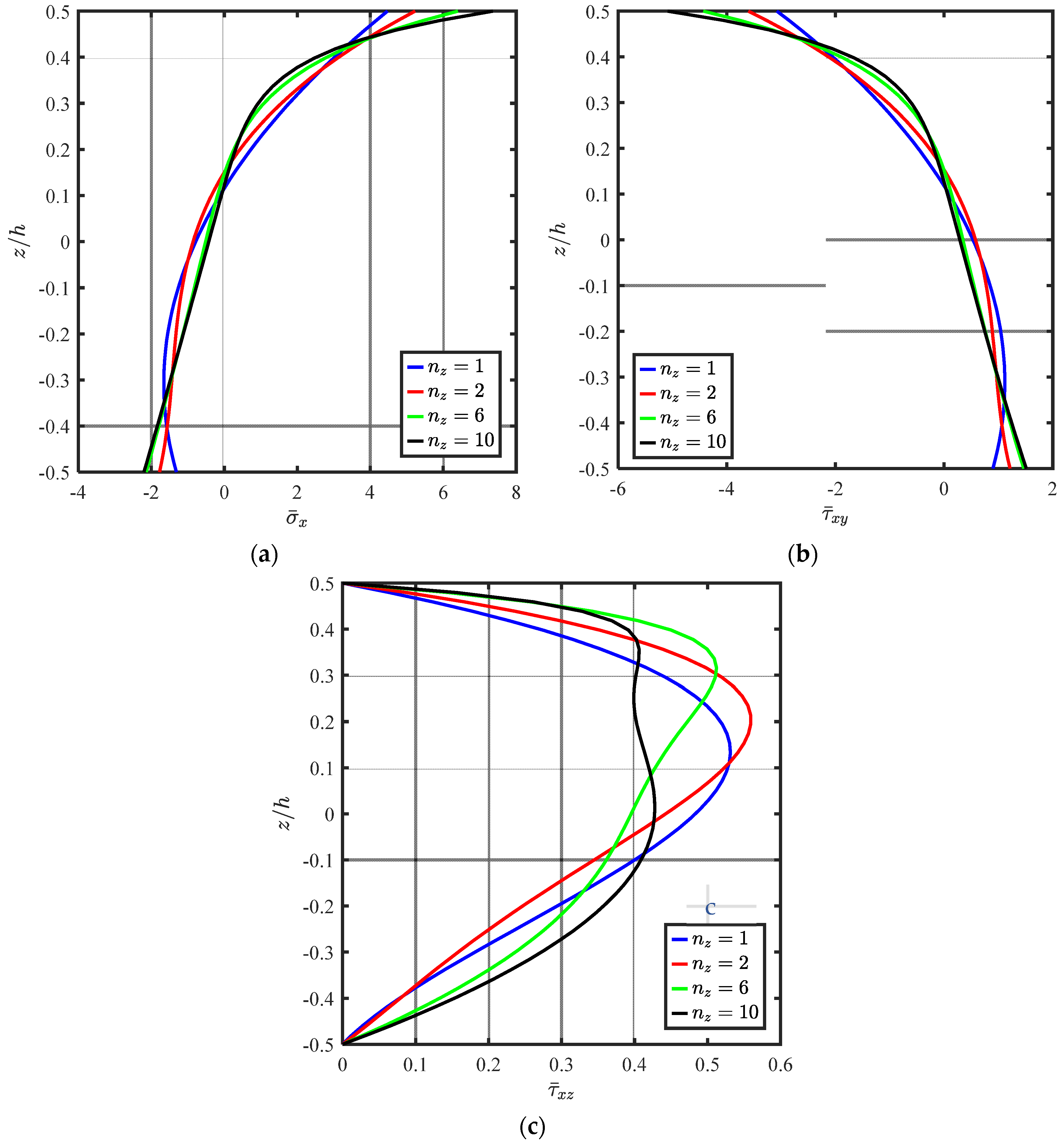
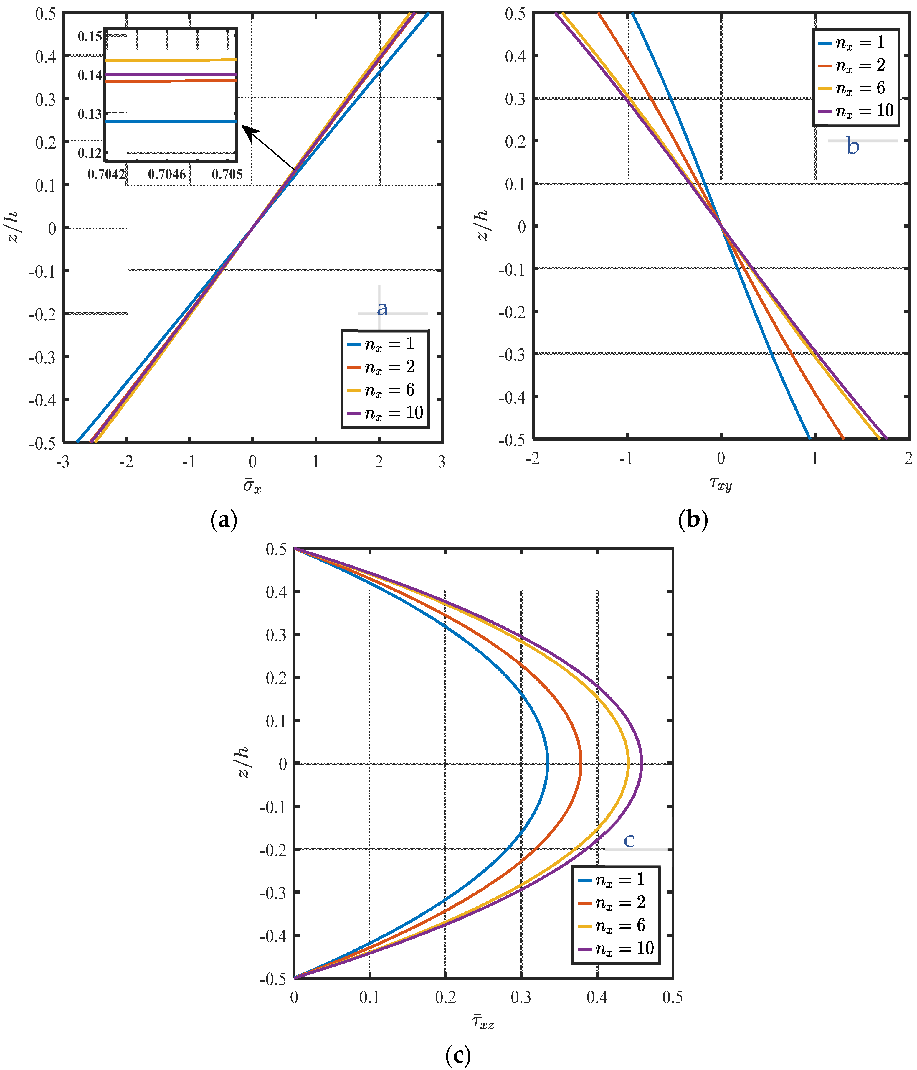
Figure 7.
Non-dimensional stresses of BDFG at different . (a) Normal stress . (b) Shear stress . (c) Shear stress .
Figure 7.
Non-dimensional stresses of BDFG at different . (a) Normal stress . (b) Shear stress . (c) Shear stress .
Figure 8.
Non-dimensional stresses of BDFG at different . (a) Normal stress . (b) Shear stress . (c) Shear stress .
Figure 8.
Non-dimensional stresses of BDFG at different . (a) Normal stress . (b) Shear stress . (c) Shear stress .
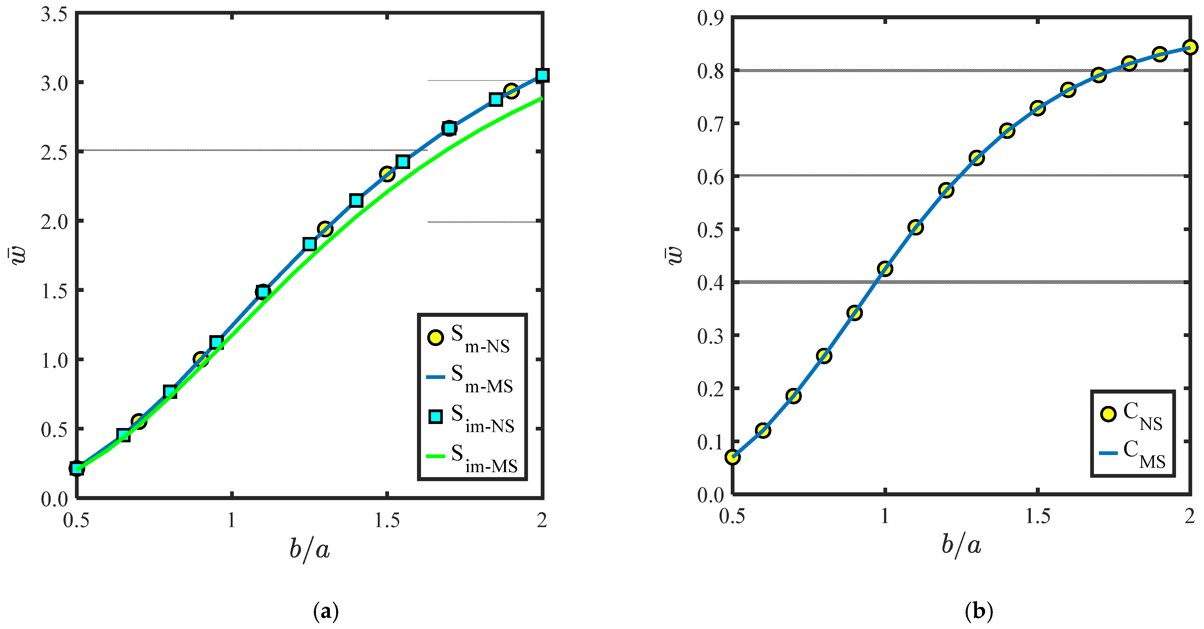
Figure 9.
Non-dimensional maximum deflection of BDFG under uniform load at different aspect ratio , . (a) Simply supported. (b) Fully Clamped.
Figure 9.
Non-dimensional maximum deflection of BDFG under uniform load at different aspect ratio , . (a) Simply supported. (b) Fully Clamped.
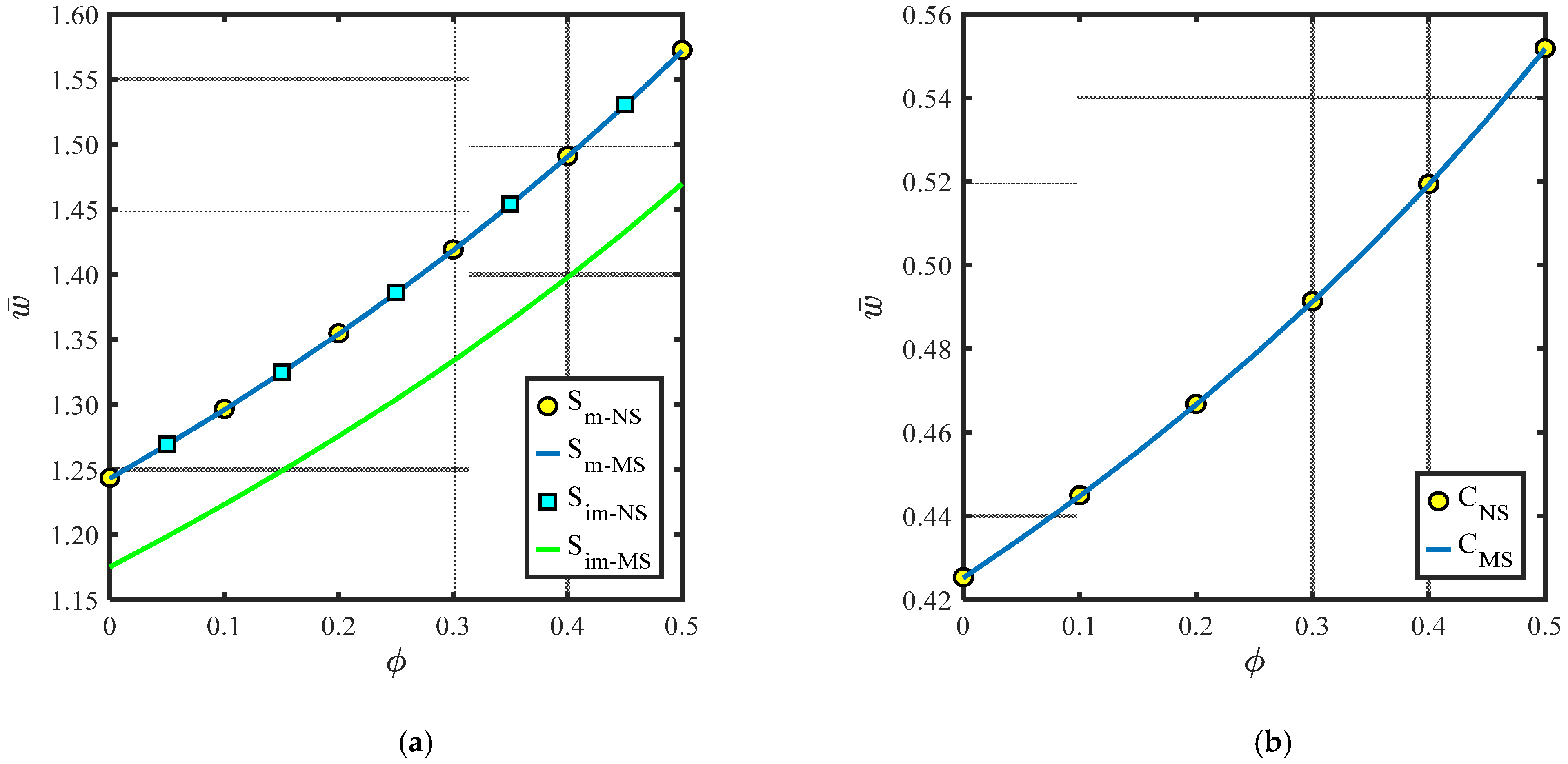
Figure 10.
Non-dimensional maximum deflection of BDFG under uniform load at a different porosity parameter (type 1), . (a) Simply Supported. (b) Fully clamped.
Figure 10.
Non-dimensional maximum deflection of BDFG under uniform load at a different porosity parameter (type 1), . (a) Simply Supported. (b) Fully clamped.
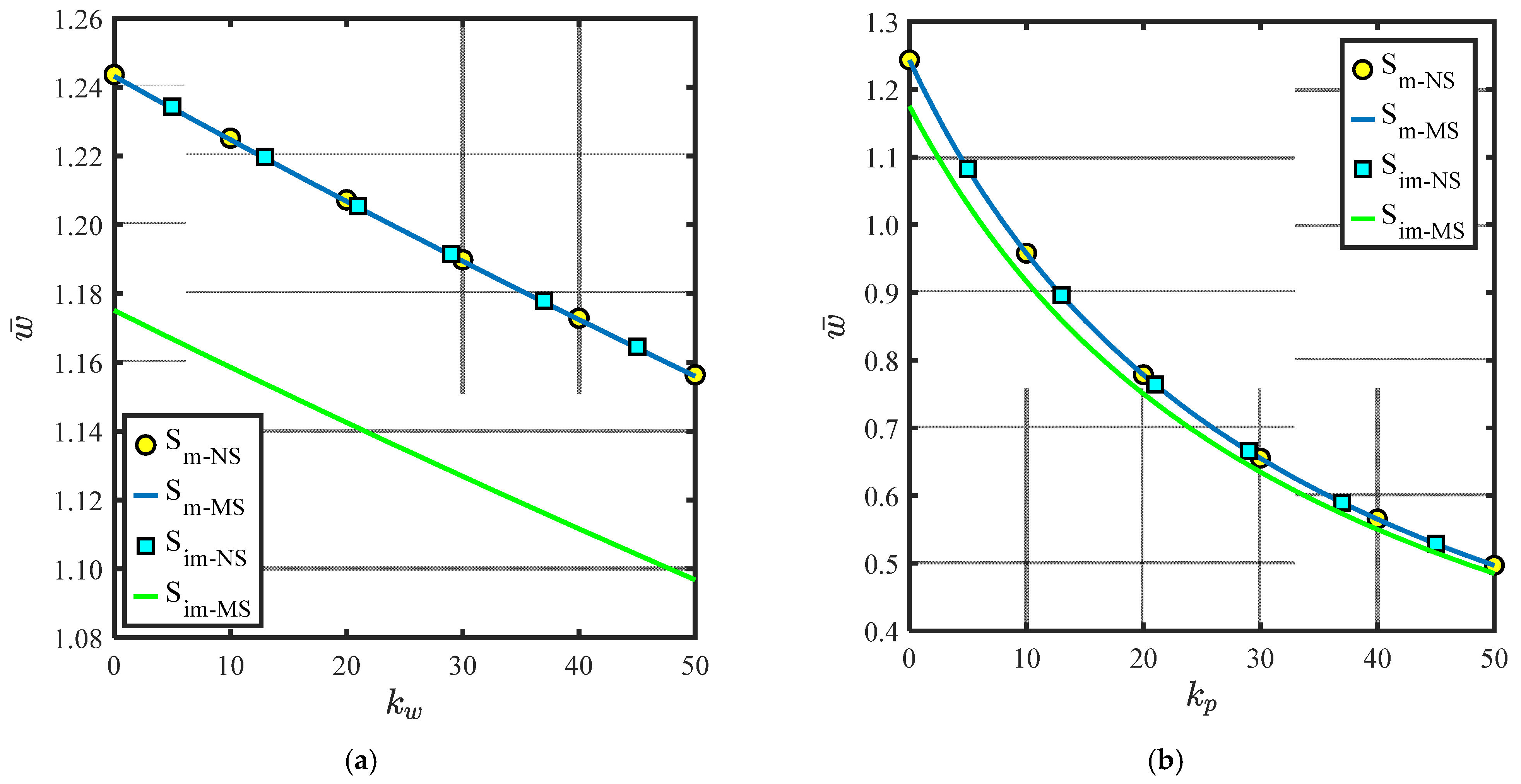
Figure 11.
Maximum deflection of BDFG under uniform load at for different and . (a) For different . (b) For different .
Figure 11.
Maximum deflection of BDFG under uniform load at for different and . (a) For different . (b) For different .
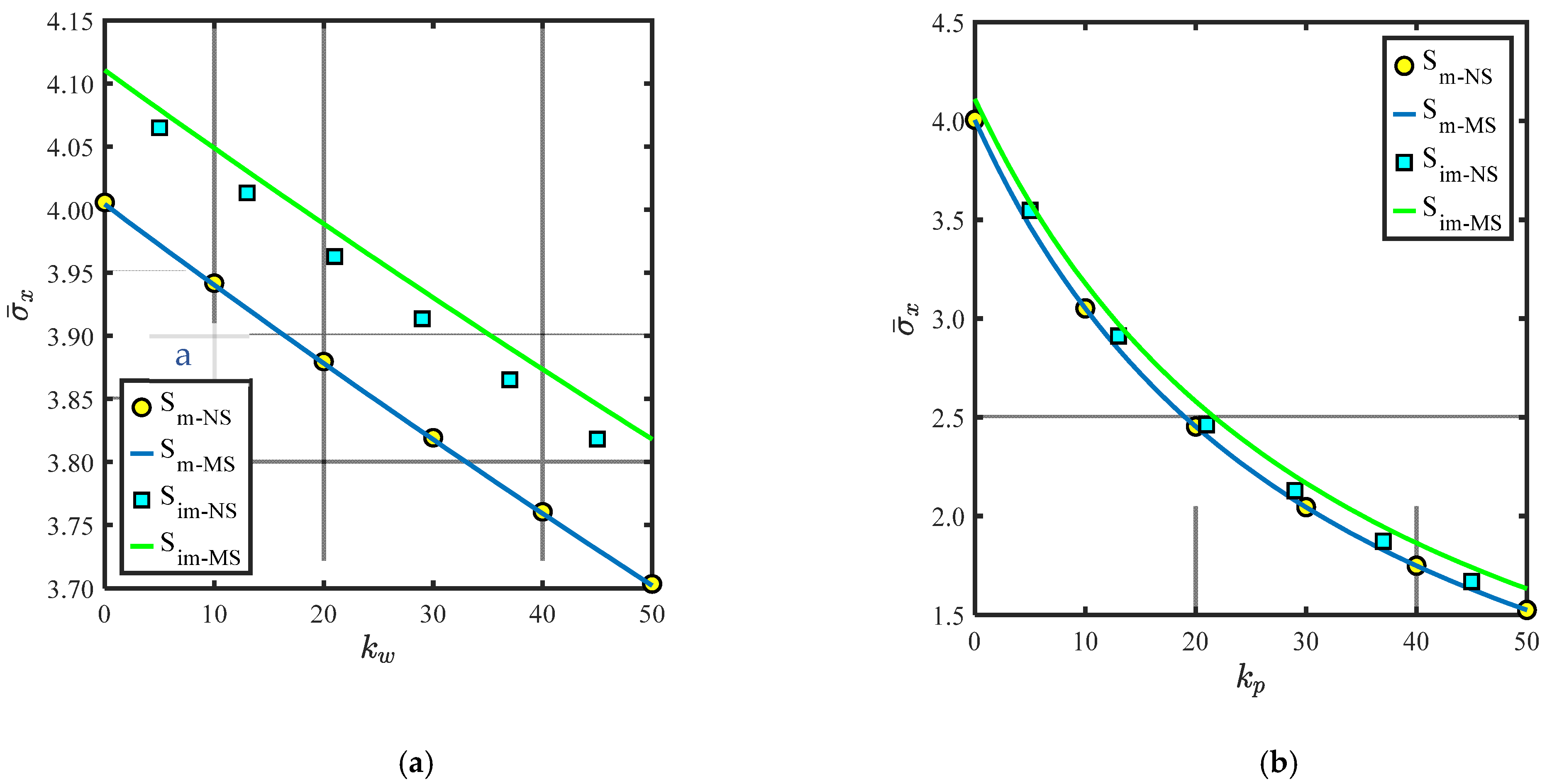
Figure 12.
Normal stress of BDFG under uniform load at for different and . (a) For different . (b) For different .
Figure 12.
Normal stress of BDFG under uniform load at for different and . (a) For different . (b) For different .
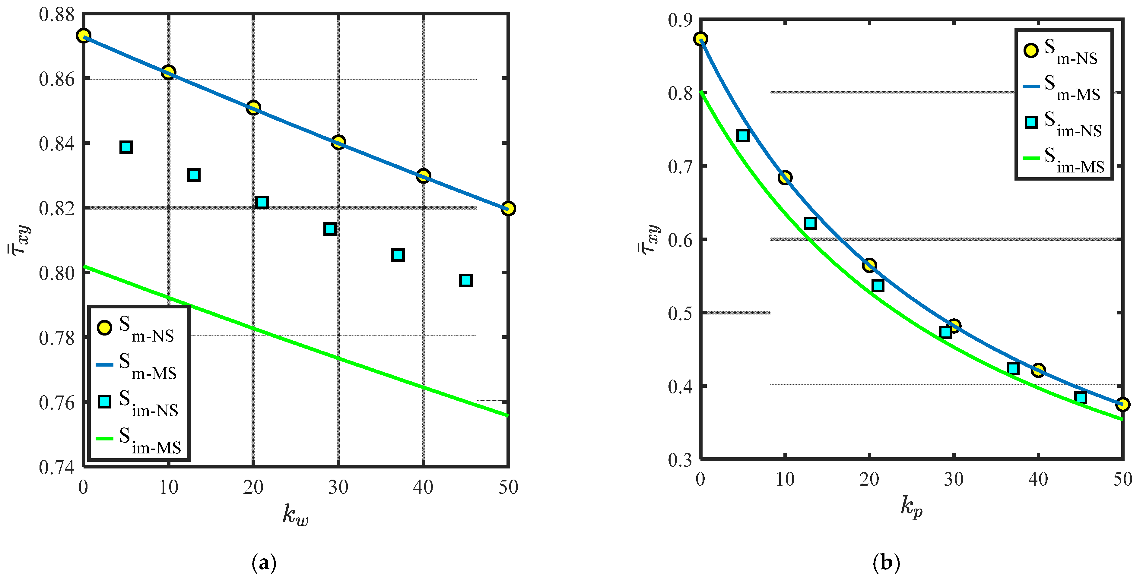
Figure 13.
Shear stress of BDFG under uniform load at for different and . (a) For different . (b) For different .
Figure 13.
Shear stress of BDFG under uniform load at for different and . (a) For different . (b) For different .
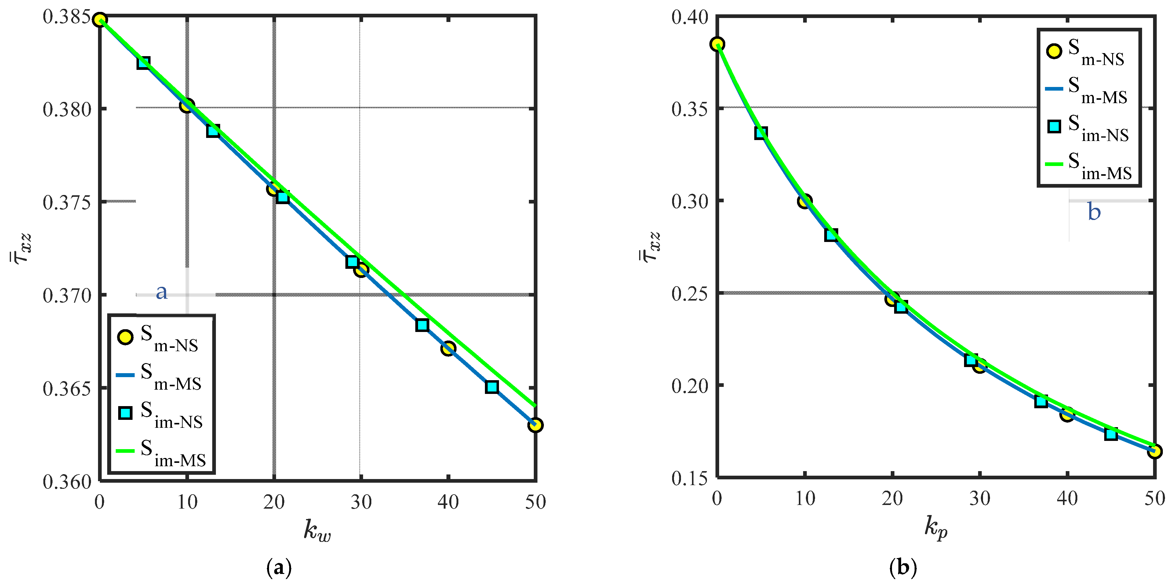
Figure 14.
Shear stress of BDFG under uniform load at for different and . Conclusion. (a) For different . (b) For different .
Figure 14.
Shear stress of BDFG under uniform load at for different and . Conclusion. (a) For different . (b) For different .
Table 1.
Comparison of the non-dimensional maximum deflection ( and ( and () of BDFG Al/Al2O3 square plate (a/h = 10) under uniform/sinusoidal transversal load based on neutral surface formulation (NS).
Table 1.
Comparison of the non-dimensional maximum deflection ( and ( and () of BDFG Al/Al2O3 square plate (a/h = 10) under uniform/sinusoidal transversal load based on neutral surface formulation (NS).
| | | |
|---|
| | |
|---|
| Present | Ref. [63] | Ref. [64] | Present | Ref. [63] | Ref. [64] | Present | Ref. [63] | Present | Ref. [63] |
|---|
| | Uniformly distributed load |
| ceramic | 0.4665 | 0.4666 | 0.4665 | 2.8917 | 2.8688 | 2.8932 | 0.0013 | 0.0013 | 0 | 0 |
| 1 | 0.9287 | 0.9290 | 0.9287 | 4.4720 | 4.4303 | 4.4745 | 0.0025 | 0.0025 | 0.1148 | 0.1148 |
| 2 | 1.1939 | 1.1952 | 1.1940 | 5.2263 | 5.1689 | 5.2296 | 0.0033 | 0.0033 | 0.1490 | 0.1490 |
| 4 | 1.3882 | 1.3908 | 1.3890 | 5.8870 | 5.8035 | 5.8915 | 0.0037 | 0.0037 | 0.1566 | 0.1566 |
| Metal | 2.5326 | - | 2.5327 | 2.8917 | - | 2.8932 | 0.0069 | 0.0069 | 0 | 0 |
| | Lateral sinusoidal load |
| ceramic | 0.2961 | 0.2961 | 0.2960 | 1.9943 | 1.9679 | 1.9955 | - | - | 0 | 0 |
| 1 | 0.5890 | 0.5891 | 0.5889 | 3.0850 | 3.0389 | 3.0870 | - | - | 0.1148 | 0.1148 |
| 2 | 0.7573 | 0.7582 | 0.7573 | 3.6067 | 3.5456 | 3.6094 | - | - | 0.1490 | 0.1490 |
| 4 | 0.8815 | 0.8831 | 0.8819 | 4.0655 | 3.9813 | 4.0693 | - | - | 0.1566 | 0.1566 |
| Metal | 1.6072 | 1.6072 | 1.6070 | 1.9943 | 1.9679 | 1.9955 | - | - | 0 | 0 |
Table 2.
Comparison of the non-dimensional maximum deflection and stresses of movable simply-supported BDFG square plate under sinusoidal load based on neutral surface formulation (.
Table 2.
Comparison of the non-dimensional maximum deflection and stresses of movable simply-supported BDFG square plate under sinusoidal load based on neutral surface formulation (.
| | | | | |
|---|
| Present | Ref. [65] | Present | Ref. [65] | Present | Ref. [65] | Present | Ref. [65] | Present | Ref. [65] |
|---|
| ceramic | 0.2961 | 0.2960 | 1.9943 | 1.9952 | 1.3124 | 1.3122 | 0.7067 | 0.7066 | 0.2386 | 0.2441 |
| 0.2 | 0.3632 | 0.3599 | 2.2739 | 2.2600 | 1.3940 | 1.3871 | 0.7304 | 0.7205 | 0.2430 | 0.2481 |
| 0.5 | 0.4546 | 0.4537 | 2.6217 | 2.6193 | 1.4603 | 1.4586 | 0.6930 | 0.6912 | 0.2441 | 0.2495 |
| 1 | 0.5890 | 0.5889 | 3.0850 | 3.0864 | 1.4898 | 1.4895 | 0.6111 | 0.6111 | 0.2386 | 0.2441 |
| 2 | 0.7573 | 0.7573 | 3.6067 | 3.6086 | 1.3960 | 1.3956 | 0.5442 | 0.5441 | 0.2186 | 0.2243 |
| 5 | 0.9113 | 0.9117 | 4.2447 | 4.2476 | 1.1041 | 1.1033 | 0.5757 | 0.5755 | 0.1929 | 0.1992 |
| Metal | 1.6072 | 1.6071 | 1.9943 | 1.9952 | 1.3124 | 1.3122 | 0.7067 | 0.7066 | 0.2386 | 0.2441 |
Table 3.
Comparison of the non-dimensional maximum deflection and stresses of movable simply supported BDFG Al/Al2O3 square plate (a/h = 10) under uniform load based on neutral surface formulation (NS) and foundations (, ) and .
Table 3.
Comparison of the non-dimensional maximum deflection and stresses of movable simply supported BDFG Al/Al2O3 square plate (a/h = 10) under uniform load based on neutral surface formulation (NS) and foundations (, ) and .
| | | | | | |
|---|
| 0.5 | 100 | 0 | | 1.8624 | 0.2247 | 0.0911 |
| Ref [66] | 1.8590 | 0.2242 | 0.0916 |
| Ref [67] | 1.8591 | 0.2242 | 0.0917 |
| Ref [68] | 1.8296 | 0.2299 | 0.0877 |
| 100 | 100 | | 1.6544 | 0.1988 | 0.0832 |
| Ref [66] | 1.6640 | 0.1999 | 0.0850 |
| Ref [67] | 1.6640 | 0.1999 | 0.0850 |
| Ref [68] | 1.6414 | 0.2054 | 0.0815 |
| 5 | 100 | 0 | | 3.5618 | 0.4816 | 0.1980 |
| Ref [66] | 3.5620 | 0.4816 | 0.1996 |
| Ref [67] | 3.5630 | 0.4817 | 0.1998 |
| Ref [68] | 3.4286 | 0.4913 | 0.1845 |
| 100 | 100 | | 2.8689 | 0.3851 | 0.1678 |
| Ref [66] | 2.9046 | 0.3897 | 0.1740 |
| Ref [67] | 2.9052 | 0.3897 | 0.1741 |
| Ref [68] | 2.8179 | 0.4006 | 0.1616 |
Table 4.
Influence of Young’s modulus ratio on the non-dimensional maximum deflection of movable/immovable simply-supported BDFG square plate sinusoidal load based on neutral surface formulation ( at .
Table 4.
Influence of Young’s modulus ratio on the non-dimensional maximum deflection of movable/immovable simply-supported BDFG square plate sinusoidal load based on neutral surface formulation ( at .
| | | | |
|---|
| | | | | | | | | | | | |
|---|
| 0.0 | 10 | 0.3657 | 0.3657 | 0.3657 | 0.3657 | 0.4528 | 0.4528 | 0.4528 | 0.4528 | 0.5022 | 0.5022 | 0.5022 | 0.5022 |
| 1 | 0.4417 | 0.4417 | 0.4379 | 0.4417 | 0.6709 | 0.6710 | 0.6472 | 0.6710 | 0.8259 | 0.8262 | 0.7791 | 0.8262 |
| 2 | 0.4615 | 0.4615 | 0.4569 | 0.4615 | 0.7487 | 0.7488 | 0.7137 | 0.7488 | 0.9716 | 0.9721 | 0.8930 | 0.9721 |
| 5 | 0.4819 | 0.4819 | 0.4790 | 0.4819 | 0.8202 | 0.8203 | 0.7924 | 0.8203 | 1.1021 | 1.1023 | 1.0297 | 1.1023 |
| 10 | 0.4982 | 0.4982 | 0.4968 | 0.4982 | 0.8762 | 0.8762 | 0.8608 | 0.8762 | 1.1951 | 1.1952 | 1.1505 | 1.1952 |
| 0.0 | 100 | 0.3464 | 0.3464 | 0.3464 | 0.3464 | 0.4280 | 0.4280 | 0.4280 | 0.4280 | 0.4745 | 0.4745 | 0.4745 | 0.4745 |
| 1 | 0.4187 | 0.4187 | 0.4149 | 0.4187 | 0.6376 | 0.6377 | 0.6139 | 0.6377 | 0.7865 | 0.7868 | 0.7397 | 0.7868 |
| 2 | 0.4366 | 0.4366 | 0.4320 | 0.4366 | 0.7088 | 0.7090 | 0.6738 | 0.7090 | 0.9217 | 0.9222 | 0.8430 | 0.9222 |
| 5 | 0.4547 | 0.4547 | 0.4518 | 0.4547 | 0.7706 | 0.7707 | 0.7428 | 0.7707 | 1.0335 | 1.0337 | 0.9611 | 1.0337 |
| 10 | 0.4703 | 0.4703 | 0.4689 | 0.4703 | 0.8225 | 0.8225 | 0.8072 | 0.8225 | 1.1173 | 1.1174 | 1.0729 | 1.1174 |
Table 5.
Influence of Young’s modulus ratio on the non-dimensional stress of movable/immovable simply-supported BDFG square plate (a/h = 10,100) sinusoidal load based on neutral surface formulation (NS) at .
Table 5.
Influence of Young’s modulus ratio on the non-dimensional stress of movable/immovable simply-supported BDFG square plate (a/h = 10,100) sinusoidal load based on neutral surface formulation (NS) at .
| | | | |
|---|
| | | | | | | | | | | | |
|---|
| 0.0 | 10 | 0.1981 | 0.1981 | 0.1981 | 0.1981 | 0.1948 | 0.1948 | 0.1948 | 0.1948 | 0.1925 | 0.1925 | 0.1925 | 0.1925 |
| 1 | 0.2266 | 0.2266 | 0.2311 | 0.2273 | 0.2605 | 0.2605 | 0.2672 | 0.2641 | 0.2816 | 0.2817 | 0.2878 | 0.2880 |
| 2 | 0.2355 | 0.2355 | 0.2406 | 0.2360 | 0.2838 | 0.2838 | 0.2918 | 0.2876 | 0.3178 | 0.3180 | 0.3245 | 0.3259 |
| 5 | 0.2499 | 0.2499 | 0.2545 | 0.2501 | 0.3182 | 0.3182 | 0.3283 | 0.3206 | 0.3659 | 0.3659 | 0.3775 | 0.3719 |
| 10 | 0.2637 | 0.2637 | 0.2672 | 0.2638 | 0.3573 | 0.3573 | 0.3673 | 0.3584 | 0.4238 | 0.4238 | 0.4384 | 0.4271 |
| 0.0 | 100 | 0.1963 | 0.1963 | 0.1963 | 0.1963 | 0.1932 | 0.1932 | 0.1932 | 0.1932 | 0.1910 | 0.1910 | 0.1910 | 0.1910 |
| 1 | 0.2244 | 0.2244 | 0.2290 | 0.2252 | 0.2580 | 0.2581 | 0.2647 | 0.2616 | 0.2790 | 0.2791 | 0.2852 | 0.2854 |
| 2 | 0.2331 | 0.2331 | 0.2382 | 0.2337 | 0.2808 | 0.2808 | 0.2888 | 0.2846 | 0.3145 | 0.3147 | 0.3211 | 0.3226 |
| 5 | 0.2474 | 0.2474 | 0.2520 | 0.2476 | 0.3146 | 0.3146 | 0.3247 | 0.3169 | 0.3614 | 0.3614 | 0.3730 | 0.3674 |
| 10 | 0.2612 | 0.2612 | 0.2647 | 0.2613 | 0.3535 | 0.3535 | 0.3635 | 0.3546 | 0.4189 | 0.4190 | 0.4335 | 0.4222 |
Table 6.
Influence of Young’s modulus ratio on the non-dimensional stress of movable/immovable simply-supported BDFG square plate (a/h = 10,100) sinusoidal load based on neutral surface formulation (NS) at .
Table 6.
Influence of Young’s modulus ratio on the non-dimensional stress of movable/immovable simply-supported BDFG square plate (a/h = 10,100) sinusoidal load based on neutral surface formulation (NS) at .
| | | | |
|---|
| | | | | | | | | | | | |
|---|
| 0.0 | 10 | 0.2054 | 0.2054 | 0.2054 | 0.2054 | 0.1699 | 0.1699 | 0.1699 | 0.1699 | 0.1488 | 0.1488 | 0.1488 | 0.1488 |
| 1 | 0.2196 | 0.2196 | 0.2196 | 0.2196 | 0.1941 | 0.1941 | 0.1941 | 0.1941 | 0.1768 | 0.1768 | 0.1768 | 0.1768 |
| 2 | 0.2269 | 0.2269 | 0.2269 | 0.2269 | 0.2091 | 0.2091 | 0.2091 | 0.2091 | 0.1956 | 0.1956 | 0.1956 | 0.1956 |
| 5 | 0.2349 | 0.2349 | 0.2348 | 0.2349 | 0.2281 | 0.2281 | 0.2280 | 0.2281 | 0.2221 | 0.2221 | 0.2218 | 0.2221 |
| 10 | 0.2375 | 0.2375 | 0.2375 | 0.2375 | 0.2354 | 0.2354 | 0.2353 | 0.2354 | 0.2334 | 0.2334 | 0.2331 | 0.2334 |
| 0.0 | 100 | 0.2057 | 0.2057 | 0.2057 | 0.2057 | 0.1703 | 0.1703 | 0.1703 | 0.1703 | 0.1494 | 0.1494 | 0.1494 | 0.1494 |
| 1 | 0.2198 | 0.2198 | 0.2198 | 0.2198 | 0.1944 | 0.1944 | 0.1944 | 0.1944 | 0.1772 | 0.1772 | 0.1772 | 0.1772 |
| 2 | 0.2271 | 0.2271 | 0.2265 | 0.2271 | 0.2094 | 0.2094 | 0.2095 | 0.2094 | 0.1959 | 0.1959 | 0.2027 | 0.1959 |
| 5 | 0.2350 | 0.2350 | 0.2354 | 0.2350 | 0.2283 | 0.2283 | 0.2229 | 0.2283 | 0.2224 | 0.2224 | 0.2099 | 0.2224 |
| 10 | 0.2377 | 0.2377 | 0.2392 | 0.2377 | 0.2356 | 0.2356 | 0.2366 | 0.2356 | 0.2336 | 0.2336 | 0.2286 | 0.2336 |
Table 7.
Maximum values of and at different and ratios .
Table 7.
Maximum values of and at different and ratios .
| | | |
|---|
| | | | | |
|---|
| 0.0 | 0.0000 | 0.0000 | 0.0000 | 0.0000 | 0.0000 | 0.0000 |
| 0.2 | 0.0214 | 0.0047 | 0.0337 | 0.0074 | 0.0381 | 0.0083 |
| 0.5 | 0.0401 | 0.0083 | 0.0669 | 0.0138 | 0.0772 | 0.0160 |
| 1 | 0.0556 | 0.0111 | 0.1000 | 0.0200 | 0.1190 | 0.0238 |
| 2 | 0.0625 | 0.0125 | 0.1250 | 0.0250 | 0.1563 | 0.0313 |
| 4 | 0.0556 | 0.0119 | 0.1250 | 0.0268 | 0.1667 | 0.0357 |
| 5 | 0.0510 | 0.0113 | 0.1190 | 0.0265 | 0.1623 | 0.0361 |
| 10 | 0.0347 | 0.0088 | 0.0893 | 0.0226 | 0.1303 | 0.0330 |
Table 8.
Influence of gradation indices on the non-dimensional maximum deflection and different stresses of immovable BDFG square plate uniform load based on neutral surface formulation ( formulation..
Table 8.
Influence of gradation indices on the non-dimensional maximum deflection and different stresses of immovable BDFG square plate uniform load based on neutral surface formulation ( formulation..
| | | | | | | | | |
|---|
| | | | |
| 0.5 | 0.8359 | 0.3876 | 0.0556 | 0.2630 | 1.0313 | 0.3630 | 0.0737 | 0.3625 |
| 1 | 0.9925 | 0.4481 | 0.0636 | 0.2987 | 1.1752 | 0.4111 | 0.0802 | 0.3848 |
| 2 | 1.1584 | 0.5105 | 0.0709 | 0.3530 | 1.3299 | 0.4599 | 0.0864 | 0.4163 |
| 5 | 1.3570 | 0.5983 | 0.0799 | 0.4302 | 1.5183 | 0.5316 | 0.0946 | 0.4578 |
| | | |
| 0.5 | 1.3514 | 0.3202 | 0.0943 | 0.3989 | 1.7829 | 0.2707 | 0.1122 | 0.4430 |
| 1 | 1.4691 | 0.3517 | 0.0991 | 0.4150 | 1.8690 | 0.2803 | 0.1148 | 0.4508 |
| 2 | 1.5898 | 0.3820 | 0.1034 | 0.4374 | 1.9466 | 0.2887 | 0.1171 | 0.4616 |
| 5 | 1.7444 | 0.4268 | 0.1087 | 0.4663 | 2.0361 | 0.2993 | 0.1197 | 0.4750 |
| | | | |
| 0.5 | 0.7977 | 0.3852 | 0.0561 | 0.2540 | 0.9809 | 0.3609 | 0.0745 | 0.3536 |
| 1 | 0.9464 | 0.4452 | 0.0643 | 0.3001 | 1.1198 | 0.4086 | 0.0811 | 0.3862 |
| 2 | 1.0981 | 0.5069 | 0.0718 | 0.3724 | 1.2607 | 0.4568 | 0.0874 | 0.4264 |
| 5 | 1.2704 | 0.5933 | 0.0811 | 0.4139 | 1.4261 | 0.5273 | 0.0957 | 0.4413 |
| | | |
| 0.5 | 1.2851 | 0.3184 | 0.0952 | 0.3903 | 1.6984 | 0.2687 | 0.1132 | 0.4323 |
| 1 | 1.3958 | 0.3494 | 0.1001 | 0.4160 | 1.7793 | 0.2783 | 0.1158 | 0.4519 |
| 2 | 1.5088 | 0.3793 | 0.1044 | 0.4468 | 1.8497 | 0.2866 | 0.1181 | 0.4811 |
| 5 | 1.6458 | 0.4235 | 0.1098 | 0.4561 | 1.9300 | 0.2972 | 0.1208 | 0.4722 |


