Article

Ergodic Capacity Analysis of Downlink Communication Systems under Covariance Shaping Equalizers

by
Ubaid M. Al-Saggaf
1,2,
Ahmad Kamal Hassan
3,* and
Muhammad Moinuddin
1,2
1
Center of Excellence in Intelligent Engineering Systems (CEIES), King Abdulaziz University, Jeddah 21859, Saudi Arabia
2
Department of Electrical and Computer Engineering, King Abdulaziz University, Jeddah 21859, Saudi Arabia
3
Faculty of Electrical Engineering, GIK Institute of Engineering Sciences and Technology, Topi 23640, Pakistan
*
Author to whom correspondence should be addressed.
Mathematics 2022, 10(22), 4304; https://doi.org/10.3390/math10224304
Submission received: 8 October 2022 / Revised: 5 November 2022 / Accepted: 14 November 2022 / Published: 17 November 2022

Abstract

:
Advances in higher-end spectrum utilization has enabled user equipment to dock multiple antenna elements, and hence make use of selectivity via equalization in new generation of mobile networks. The equalization can exploit channel statistics to shape covariance matrices, and hence improve network performance at the physical layer of these networks by projecting segregated signals to non-overlapping subspaces. We propose to establish the promise of covariance shaping method by incorporating the equalizers in the modelling of a downlink multi-user multiple-input multiple-output (MU-MIMO) systems and thereby characterizing a key performance indicator, namely, the sum ergodic capacity. This is achieved by utilizing a residue theory approach which can account for indefinite eigenvalues. The system modelling is generic in a sense that it requires the base station (BS) to only have second order statistics of the channel rather than instantaneous knowledge. Furthermore, the BS incorporates a transmit beamformer design to enhance the ergodic capacity and feedforward the information of covariance shaping equalizers. Search method for transmit beamforming is also proposed which shows a promising three fold increase in sum ergodic capacity at signal-to-noise ratio of 10 dB for the considered MU-MIMO system. Proposed characterization of the system is authenticated using simulation means, and a comparative analysis of transmit beamformer designs on the sum ergodic rate is showcased.

1. Introduction

Numerous research frontiers are explored in telecommunication sector for beyond-5G (B5G) wireless communications networks in order to meet the ever-increasing spectrum demands [1]. Research directions for the conventional and B5G networks are often categorized based on the level of knowledge, and the uncertainty in estimation of channel state information (CSI). Primarily, two levels of CSI information are instantaneous and statistical, each level is pertinent for a specific set of applications. In a downlink multi-user multi-input multi-output (MU-MIMO) system, much of the existing literature assumes instantaneous CSI at the base station (BS) e.g., as in [2]. Relaying instantaneous CSI to the BS would require a sizable proportion of the bandwidth and hence relaying only statistics of CSI can be a better option for bandwidth constrained networks. Hence, there is a need for analysis of statistical CSI based systems.
System modelling, statistical inferences, and analysis of the MU-MIMO systems are explored in previous works by either adopting a generic channel design, or by perceiving a separable transmit and receiver covariance matrices as in the Kronecker structured channel model [3]. Methods of estimating these matrices are pointed out in [4], however, statistics of the channel can be considered known with certain level of certainty. The Kronecker structured channel model yields pessimistic results [5] in terms of key performance indicators (KPIs) due to strong assumption of separable transmit and receiver correlation matrices. However, the former, i.e., the generic channel design is recently proposed in [6,7] and it utilizes a covariance shaping methodology to incorporate an effective equalizer design of the MU-MIMO system. This scheme makes use of geographical location of user equipment (UE) and hence projects the radiated signal to the subscriber UE on orthogonal subspaces by reshaping channel covariance statistics and hence reducing the interference incurred by multiple users. While the seminal work of covariance shaping model was given in [6], but it was limited to only 2 users. This assumption was later relaxed in [8] and the proof of convergence was also given to ensure an effective equalizer design. Under the covariance shaping scheme, a significant key performance indicator (KPI), i.e., the outage probability of a given user was characterized by employing indefinite quadratic formulation based residue theory approach. However, another significant performance metric, i.e., the sum ergodic capacity under the covariance shaping mechanism is not characterized. Ergodic capacity gives an upper bound on the dependable transmission of data over a fading channel and its characterization for the covariance shaping based MU-MIMO systems would yield a much-needed analysis of B5G networks.
Ergodic capacity of an ergodic channel is simply the average of a log of signal-to-interference-plus-noise ratio (SINR) [9]. Computing cumulative distributive function (CDF), i.e., the outage probability formulates a mathematical relationship with the ergodic capacity. In literature, usually an instantaneous SINR with known instantaneous CSI is considered for system modelling. However, when only the channel statistics are known at the transmit side, then the characterization of KPIs are more involved. Specifically, in literature, solutions of KPIs are of numerical nature, e.g., [10], or exact solutions albeit with assumptions on channel conditions as in [11,12,13]. More recently, in [14], an exact closed-form expression of ergodic capacity is characterized for a MU-MISO setup given in [15]. However, to the best of our knowledge, no work is done to characterize the ergodic sum rate of a covariance shaping based downlink MU-MIMO communication system. Also, the sum ergodic capacity provides a simple and single objective function which can be utilized as a constrained maximization problem. The solutions to such problems can be both sub-optimal closed-form as well as exhaustive search based on constrained nonlinear tools, e.g., as in [16,17]. Hence, there is a need for the characterization of sum ergodic capacity and for the design of transmit and receive beamformers.
In this paper, we observe the aforementioned requirements and shape our significant contributions in a three-fold manner. First, we formulate the SINR expressions in a canonical quadratic formulation by adopting the strategies proposed in [6,8]. Primarily, we utilize equalizer vectors for covariance shaping and include them as weights for Rayleigh channel vectors. Second, we characterize the sum ergodic capacity of downlink MU-MIMO system by employing Theorem 1 in [14], albeit now under the covariance shaping mechanism. Herein, both transmit and receive beamformers have closed-form iterative solutions. Lastly, an exhaustive search solution for the transmit beamforming is proposed by making use of a non-linear optimization toolbox in [18]. The last contribution is relevant since BS can have enough computational resources to engage the exhaustive search methods.
After the Introduction section, system model of the covariance shaping strategy is given in Section 2. Section 3 outlines the use of residue theory in the characterization of sum ergodic capacity. Section 4 provides an iterative closed-form design of transmit and receive beamformers. A search method is proposed in Section 5. Results, Conclusions, and References Sections follow next.
Notations: Scalars, vectors, and matrices are expressed using italic, bold, and bold-capital letters, respectively. ⊗, E { . } , and V m a x ( A ) represents the Kronecker product, expectation function and principal eigenvector of matrix A, respectively. u ( . ) , and E 1 ( . ) denote the unit step and exponential integral functions, respectively.
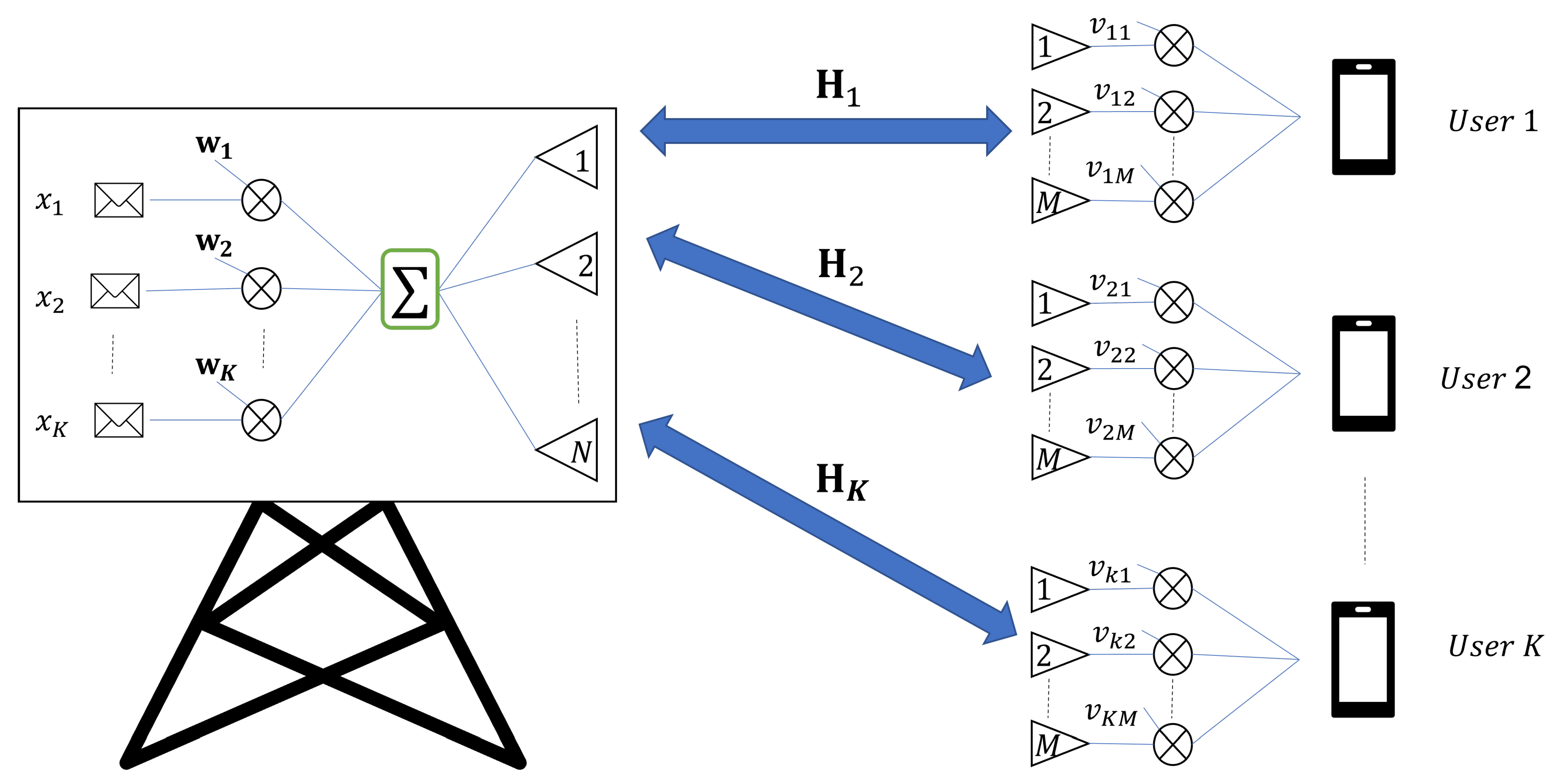
2. System Model

The system model under consideration is a fairly standard downlink MU-MIMO network shown in Figure 1. It consists of a total of K users and a single BS. Number of antenna elements of the user equipment and BS are M and N, respectively, and the plurality of antenna elements are to harvest the antenna diversity gain. For a given user, i.e., k , k { 1 , 2 , , K } , the message signal is x k which is multiplied with a precoder vector w k C N × 1 , k . The kth user receives the signal from its antenna elements and multiplies with the equalization vector v k C 1 × M . For data symbol, precoding and equalization vectors, unity power normalization is considered. Now, for the kth user, the observed signal is as follows:
y k = v k H k w k x k + i = 1 , i k K v k H k w i x i + n k .
Here, the first two terms represent the desired component and the co-channel interference component while the third term, i.e., n k is additive white noise of kth user and it power is σ k 2 , H k C M × N channel matrix and its vectorized version is vec ( H k ) CN ( 0 , Σ k ) , where Σ k is given by [6]
Σ k Σ k , 11 Σ k , 12 Σ k , 1 N Σ k , 12 H Σ k , 22 Σ k , 1 N H Σ k , N N ,
while Σ k , i j E [ h k , i h k , j H ] , i , j is an M × M block matrix.
For the kth user, the instantaneous SINR is computed as follows,
γ k = | v k H k w k | 2 σ k 2 + i = 1 , i k K | v k H k w i | 2 .
Next, we remodel (3) in two distinct forms. First, we adopt a Kronecker structured channel modelling, later we move towards the covariance shaping general channel modelling.

2.1. Kronecker Structured Model

The Kronecker structured channel model, e.g., as in [3] has rather a simple SINR structure where the covariance matrices at the transmit and receive side, i.e., ( T k ) and ( R k ), respectively, can be disjointed. Hence, the channel matrix H k is reformulated as,
H k = R k 1 2 H ¯ k T k 1 2 ,
where H ¯ k CN ( 0 , I ) , i.e., a white channel with identity correlation matrix I . Thus, the SINR expression in (3) can be reformulated as
γ k = | v ¯ k H ¯ k w ¯ k | 2 σ k 2 + i = 1 , i k K | v ¯ k H ¯ k w ¯ i | 2 , = w ¯ k H H ¯ k H v ¯ k H v ¯ k H ¯ k w ¯ k σ k 2 + i = 1 , i k K w ¯ i H H ¯ k H v ¯ k H v ¯ k H ¯ k w ¯ i ,
where in the first equality we have reformed the beamforming vectors as v ¯ k = v k R k 1 2 and w ¯ k = T k 1 2 w k .
Next, representing H ¯ k in terms of its vectorized version, h ¯ k = vec ( H ¯ k T ) C N M × 1 , we simplify the expression by using H ¯ k w ¯ k = I M w ¯ k T h ¯ k , k . Hence under this methodology, we can express γ k in the canonical quadratic form as
γ k = h ¯ k H I M w ¯ k T H v ¯ k H v ¯ k I M w ¯ k T h ¯ k σ k 2 + h ¯ k H i = 1 , i k K I M w ¯ i T H v ¯ k H v ¯ k I M w ¯ i T h ¯ k .

2.2. Covariance Shaping Model

The covariance shaping model is adopted from [6] and it is used to achieve orthogonality of covariance matrices observed at users. Now, for the kth user, transmit correlation ( T k E [ H k H H k ] C N × N ) and receive correlation ( R k E [ H k H k H ] C M × M ) are shaped by using v k , k preemptively albeit with the trade-off in terms of an effective single stream transmission and hence effectively making sort of MISO configuration. Hence with this preamble, h ¯ k v k H H k C 1 × N and the transformed channel is h ¯ k CN ( 0 , Ψ k ) with covariance matrix Ψ k is simply, Ψ k = ( I N v k H ) Σ k ( I N v k ) T .
Thus, we can express γ k as follows:
γ k = h ¯ k H w k w k H h ¯ k σ k 2 + h ¯ k H i = 1 , i k K w i w i H h ¯ k .

3. Characterization of Sum Ergodic Capacity

In this section, a closed-form expression of the sum ergodic capacity albeit under the modern covariance shaping mechanism is derived. The choice of (7) is without loss of generality as similar framework holds for (6). The sum ergodic capacity denoted as S is as follows:
S = k = 1 K E l o g 2 1 + γ k ,
= k = 1 K E l o g 2 1 + h ¯ k H w k w k H h ¯ k σ k 2 + h ¯ k H i = 1 , i k K w i w i H h ¯ k .
Now, by employing the framework given in [14], which includes partial fraction expansion and residue theory based integration simplification, the exact closed-form equation of S is given by:
S = 1 ln ( 2 ) k = 1 K [ n = 1 N λ n , k N 1 u = 1 , u n N ( λ n , k λ u , k ) e 1 λ n , k E 1 1 λ n , k u λ n , k n = 1 N ν n , k N 1 u = 1 , u n N ( ν n , k ν u , k ) e 1 ν n , k E 1 1 ν n , k u ν n , k ] ,
where λ t , k and ν t , k are the tth eigenvalues of the kth user and they are from Hermitian matrices w k w k H + i = 1 , i k K w i w i H and i = 1 , i k K w i w i H , respectively.
The aforementioned closed-form expression holds for indefinite eigenvalues and hence it is generic. More specifically, the product appearing in (10) accounts for both positive and negative eigenvalues while the summation function is handled using u ( . ) . Also, the closed-form S serves as an objective function for the maximization problem considered next.

4. Closed-Form Statistical Beamformer Solution

This section provides a statistical beamforming solution which maximizes the sum ergodic capacity in (10). While we primarily focus on the covariance shaping model in the design of receive beamformers, the methods proposed for precoding is equally beneficial for Kronecker structured model. Consider a constrained optimization problem as follows:
max . { w k , v k } k = 1 K Φ S { w k } , { v k } , s . t . w k 2 = 1 , k , v k 2 = 1 , k .
Here, the constraints on the beamformer norms normalizes both the BS’s transmission power and the receive equalizers. We use the set Φ to denote a sequential optimization structure starting with a closed-form iterative receive beamformer design viz. a covariance shaping methodology which is followed by a transmit beamformer design in the second stage.

4.1. Receive Beamforming

The aim of receive beamforming is to shape equalizer vectors v k so that the cross-covariance matrices among the users approach orthogonality. Mathematically,
v k = arg min . v k 2 = 1 Ψ k Ψ i k ,
The global solution desires exhaustive search techniques which are not desired for battery operated and limited computationally capable user devices. Hence, an alternate solution which uses a Generalized Rayleigh-Quotient based iterative approach [8], is now designed for the covariance shaping based sum ergodic structure. Since the equalization is dependent only on the channel statistics which remain true for longer duration of time, receive beamforming needs the re-tuning only when statistics of the channel change.

4.2. Transmit Beamforming

The goal of transmit beamformer is to maximize the sum ergodic capacity again under power loading constraints. Hence, a maximization problem is formulated as follows:
max . { w k } k = 1 K S { w k } k = 1 K , s . t . w k 2 = 1 , k , E l o g 2 1 + γ k i n i t . E l o g 2 1 + γ k o p t . , k .
Here, the first constraint is used to limit the transmit power and the second constraint ensures that initialized ergodic capacity is always smaller than optimized ergodic capacity for all users. The aforementioned objective function unfortunately does not have a closed-form global solution. Nevertheless, a local albeit a closed-form solution is in terms of considering the principal eigenvalue of Ψ k , k as the transmit beamformer.
Algorithm 1 outlines the transmit and receive beamformer designs proposed in this section.
Algorithm 1 Construct of Beamformers
1:
Input: K, N, M, { w k i n t i . ; v k i n t i . } k = 1 K .
2:
Output: S , { w k o p t . ; v k o p t . } k = 1 K .
3:
Set maximum iterations ( i m a x ) and  precision accuracy level ( ϵ ).
4:
i = 1
5:
Compute J ( i ) v k = v k H l = 1 , l k K i , j = 1 N v l H Σ l , i j v l v l H R l v l * Σ k , i j v k v k H R k v k , k .
6:
repeat
7:
       i = i + 1
8:
       k = 1
9:
      repeat
10:
           v k ( i ) V m i n R k 1 l = 1 , l k K i , j = 1 N v l H Σ l , i j v l v l H R l v l * Σ k , i j ( i 1 ) .
11:
           k = k + 1
12:
      until  k = K + 1
13:
      Compute J ( i ) v k = v k H l = 1 , l k K i , j = 1 N v l H Σ l , i j v l v l H R l v l * Σ k , i j v k v k H R k v k , k .
14:
      if  { | J ( i ) ( v k ) J ( i 1 ) ( v k ) | ϵ } k = 1 K & & { i = i m a x }  then
15:
            w k ( i ) V m a x ( I N v k H ) Σ k ( I N v k ) T ( i 1 ) .
16:
           Compute S using (10).
17:
          set  Condition = true.
18:
      end if
19:
until {Condition = true}

5. Exhaustive Search Based Transmit Beamformer Design

This section provides an exhaustive search based statistical transmit beamforming solution which maximizes the sum ergodic capacity in (10). For the equalizers, we use the covariance shaping defined in Algorithm 1. However, noting that the BS has much higher computational power and resources, the transmit beamforming can be approached using search methods. To this end, we formulate the constrained maximization problem as follows:
max . { w k } k = 1 K S { w k } k = 1 K , s . t . w k 2 1 , k .
In order to solve the aforementioned problem, we utilize the Interior-Point (IP) method. This methods proceeds to synthesize and solve sequence of approximate minimization problems by means of slack variables [16,17,18]. The IP method solves the approximate sub-problems by means of linear approximation and trust region. Algorithm 2 outlines the IP method based optimization for the transmit beamforming design.
Algorithm 2 Construct of Exhaustive Search based Transmit Beamformer Design
1:
Input: K, N, M, { w k Alg . 1 ; v k o p t . } k = 1 K .
2:
Output: S , { w k o p t . } k = 1 K .
3:
Set maximum iterations ( i m a x ) and  precision accuracy level ( ϵ ).
4:
i = 1
5:
Compute S ( i ) in (10) using { w k Alg . 1 ; v k o p t . } k = 1 K .
6:
repeat
7:
       i = i + 1
8:
      Compute S ( i ) in (10) using IP method on (14).
9:
      Update local optimal beamformer { w k o p t . } k = 1 K .
10:
      if  { | S ( i ) ( . ) S ( i 1 ) ( . ) | ϵ } & & { i = i m a x }  then
11:
           set Condition = true.
12:
      end if
13:
until {Condition = true}

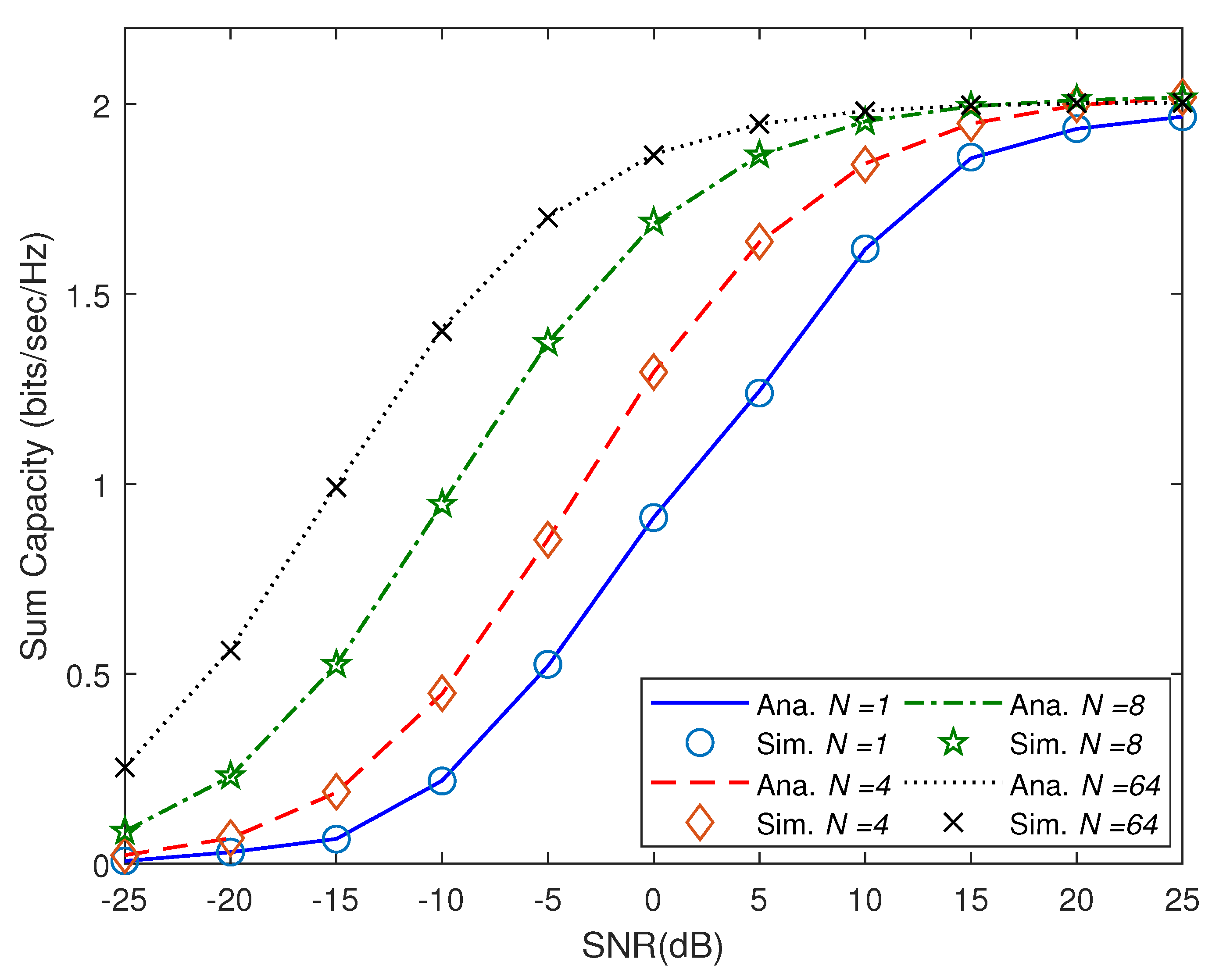
6. Results and Discussions

In order to validate the closed-form expression in (10), we have used simulation means. The correlation matrices are initialized using distinct exponential correlation coefficients. Moreover, design of the transmit beamformers are based on the criterion defined in Algorithm 1. Therein, the precoding and equalization vectors are initialized through the principal eigenvector of correlation matrices. In Figure 2, the sum capacity in bits/sec/Hz is plotted versus transmit SNR in dB scale. We set K = 2, M = 4 and vary the number of transmit antennas. The antenna diversity gain is observed across the SNR range. For instance, at 0 dB, there is a two fold increase by increase the number of transmit antennas from 1 to 64. Also, the antenna diversity gain increases rapidly initially and later the rate of increase slows down at higher antenna order as expected. Importantly, for all cases of the number of transmit antennas N, excellent match is observed between the analytical results and simulation ones. Next in
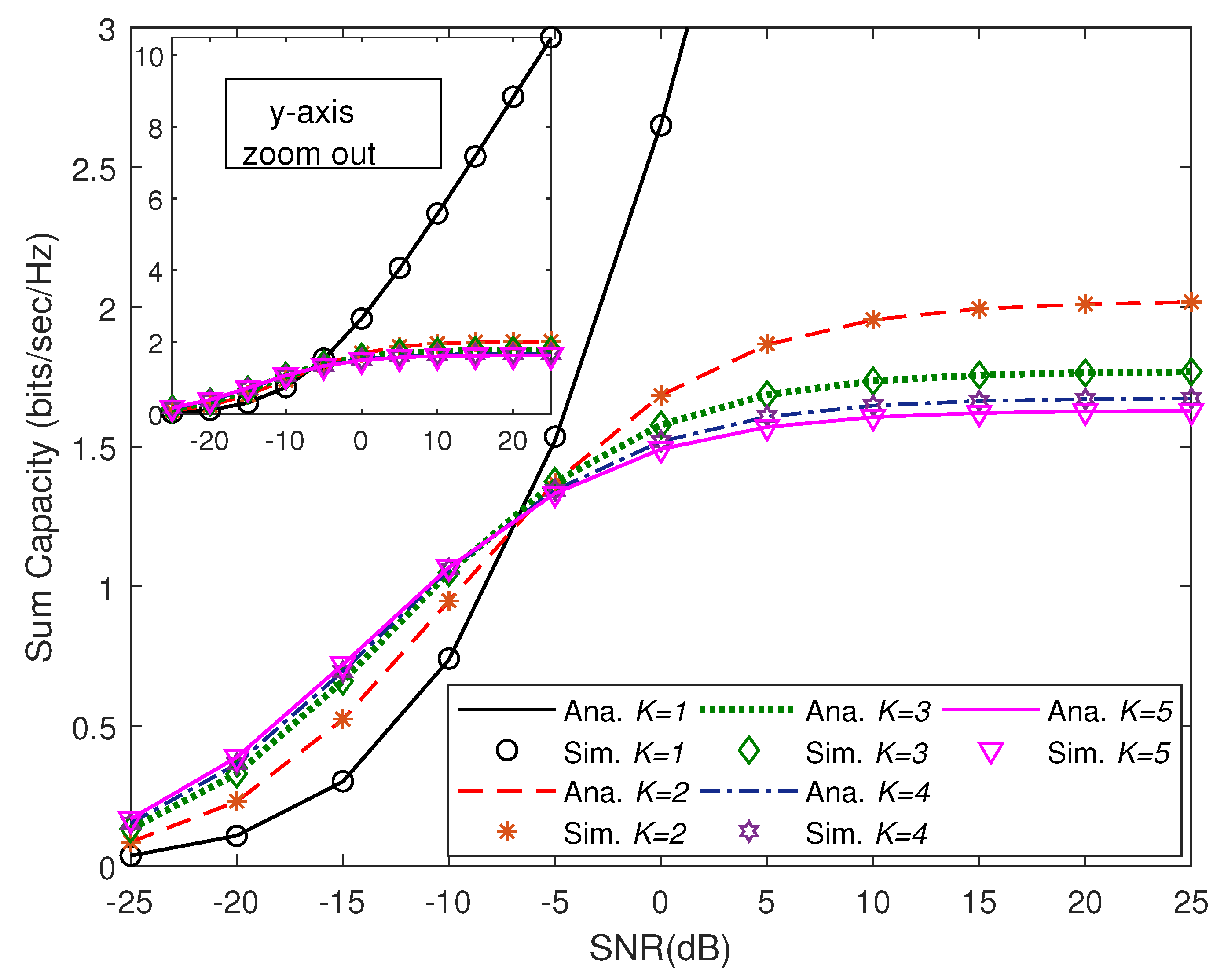
 Figure 3, we set N = 8, M = 4 and check the performance by varying the number of users K. It is observed that at low SNR, noise is the main limiting factor, while at high SNR values, interference plays the main role. Again, a perfect match between analytical and simulation results is observed across the SNR range.
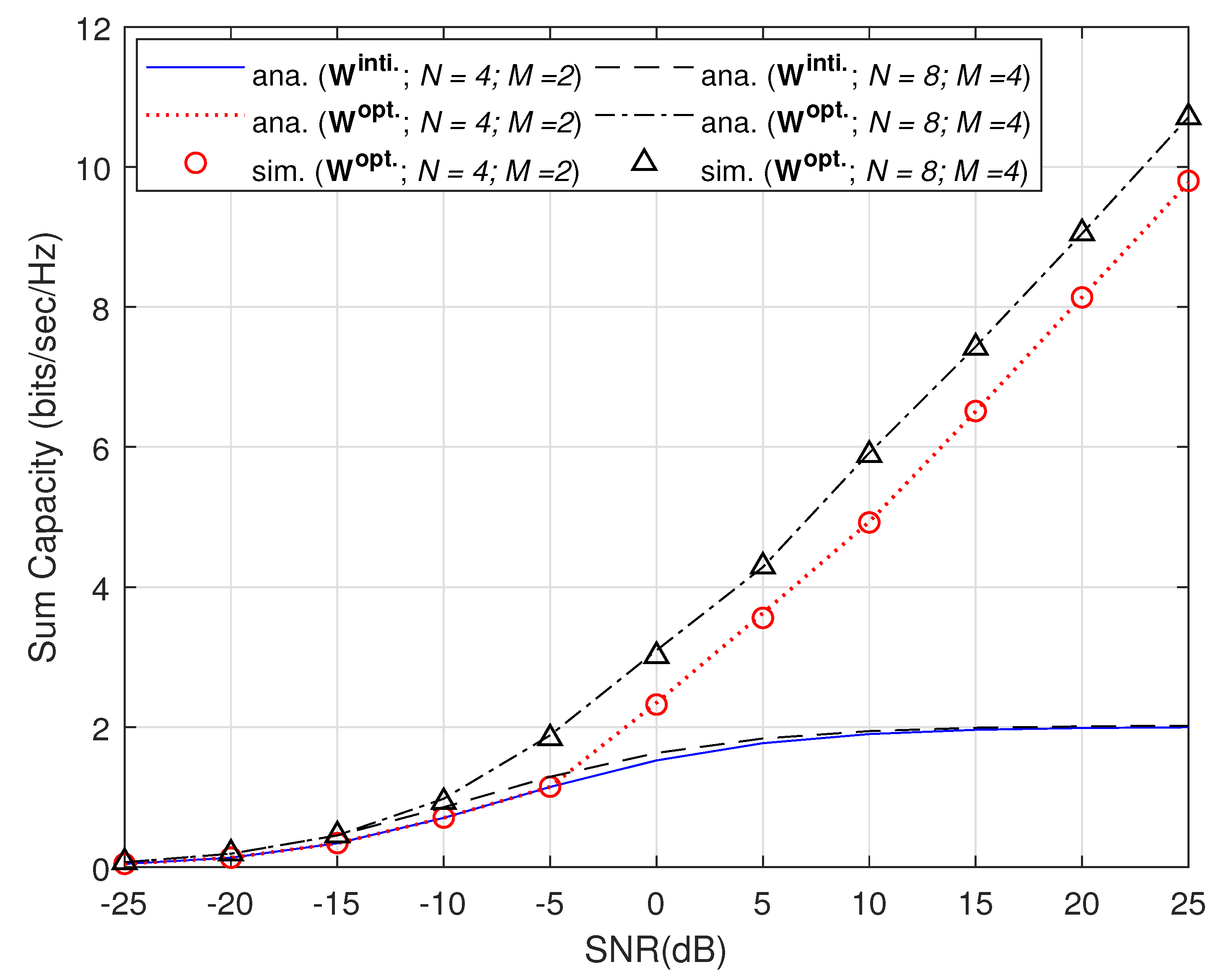
Next, we present the results based on exhaustive search method outlined in Algorithm 2. We set K = 2 and vary the number of transmit and receive antennas and check the efficiency of Algorithm 2 on the set conditions and also validate the optimized beamformers using Monte Carlo runs. Herein, the transmit and receive beamformer are initialized from the output of Algorithm 1, i.e., { w k Alg . 1 ; v k o p t . } , k . In Figure 4, we present the sum ergodic capacity versus SNR in dB by comparing the initialized transmit beamformer with the optimized transmit beamformer viz Algorithm 2 for two network configurations. Specifically, the two network configurations are N = 4; M = 2 and N = 8; M = 4, respectively. For both, the improvement is across the SNR range, and their is approximately an exponential slope of sum capacity increase at high SNR regimes. For N = 8; M = 4 a three fold increase is observed at 10 dB and this further increases at even higher SNR values. Simulations are used to validate the new transmit beamformer and again there is an exact match. In 
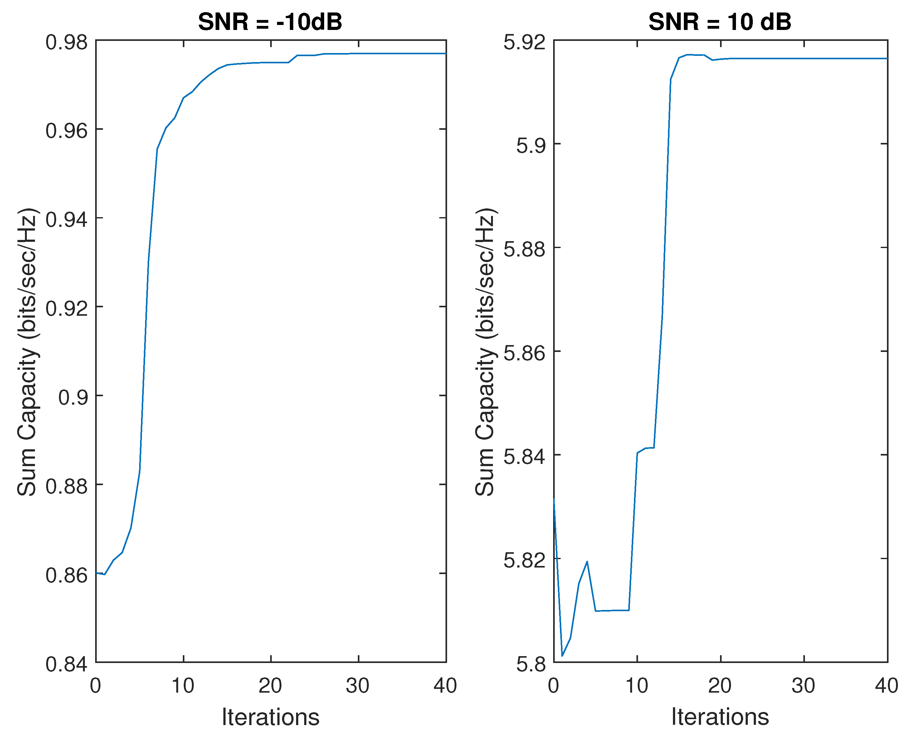
Figure 5, the convergence of sum ergodic capacity versus iterations is shown for SNR values of −10 dB and 10 dB for N = 8; M = 4. The convergence is observed well before 30 iterations for both the cases and a good degree of maximization is observed.

7. Conclusions

In this paper, we formulated canonical SINR forms using a Kronecker and covariance shaping model and utilized these SINR expressions in an expectation operator to achieve an exact closed-form expression of the sum ergodic capacity while considering only statistical CSI at BS. Using the proposed characterization, transmit and receive beamformers are designed and two algorithms are presented. The first algorithm is validated using simulations and it showed the sum ergodic capacity as a function of SNR under low complexity iterative solution. Next, we proposed the second algorithm which benefits from high computational resources at the BS and it showed marked improvement in the KPIs under the tested region and configurations. The second algorithm is also validated by simulation means. The sum capacity improvement showcased is subject to an effective transformation from MU-MIMO to MU-MISO system and therefore valid only for single stream of data. Hence, modelling and analysis of a generic MU-MIMO system by relaxation of such transformation is an interesting area to work on. Furthermore, this work opens door for other B5G networks setups such as intelligent reflective surfaces, cooperative communication, and non-orthogonal multiple access networks where similar closed-form expressions of KPIs and the respective beamformer designs can be formulated.

Author Contributions

Conceptualization, U.M.A.-S., A.K.H. and M.M.; methodology, U.M.A.-S., A.K.H. and M.M.; software, A.K.H.; validation, A.K.H.; formal analysis, U.M.A.-S., A.K.H. and M.M.; investigation, U.M.A.-S., A.K.H. and M.M.; resources, U.M.A.-S.; writing—original draft preparation, U.M.A.-S., A.K.H. and M.M.; writing—review and editing, U.M.A.-S. and M.M.; supervision, U.M.A.-S.; project administration, U.M.A.-S.; funding acquisition, U.M.A.-S.; All authors have read and agreed to the published version of the manuscript.

Funding

The Deanship of Scientific Research (DSR) at King Abdulaziz University (KAU), Jeddah, Saudi Arabia, has funded this project under grant no (G: 151-135-1443).

Institutional Review Board Statement

Not applicable.

Informed Consent Statement

Not applicable.

Data Availability Statement

Not applicable.

Acknowledgments

This work was funded by the Deanship of Scientific Research (DSR), King Abdulaziz University, Jeddah, under Grant no. (G: 151-135-1443). The authors, therefore, acknowledge with thanks DSR for their technical and financial supports.

Conflicts of Interest

The authors declare no conflict of interest.

References

  1. Anonymous. Global Mobile Data Traffic Forecast Update, White Paper, 2018–2023; Cisco Visual Networking Index; 2020. [Google Scholar]
  2. Gesbert, D.; Kountouris, M.; Heath, R.W.; Chae, C.B.; Salzer, T. Shifting the MIMO paradigm. IEEE Signal Process. Mag. 2007, 24, 36–46. [Google Scholar] [CrossRef]
  3. Weichselberger, W.; Herdin, M.; Ozcelik, H.; Bonek, E. A stochastic MIMO channel model with joint correlation of both link ends. IEEE Trans. Wirel. Commun. 2006, 5, 90–100. [Google Scholar] [CrossRef] [Green Version]
  4. Werner, K.; Jansson, M.; Stoica, P. On estimation of covariance matrices with Kronecker product structure. IEEE Trans. Signal Process. 2008, 56, 478–491. [Google Scholar] [CrossRef]
  5. Jafar, S.A.; Goldsmith, A. Multiple-antenna capacity in correlated Rayleigh fading with channel covariance information. IEEE Trans. Wirel. Commun. 2005, 4, 990–997. [Google Scholar] [CrossRef]
  6. Mursia, P.; Atzeni, I.; Gesbert, D.; Cottatellucci, L. Covariance shaping for massive MIMO systems. In Proceedings of the 2018 IEEE Global Communications Conference (GLOBECOM), Abu Dhabi, United Arab Emirates, 9–13 December 2018; pp. 1–6. [Google Scholar]
  7. Mursia, P.; Atzeni, I.; Cottatellucci, L.; Gesbert, D. Enforcing Statistical Orthogonality in Massive MIMO Systems via Covariance Shaping. IEEE Trans. Wirel. Commun. 2022, 21, 10. [Google Scholar] [CrossRef]
  8. Hassan, A.K.; Moinuddin, M.; Al-Saggaf, U.M.; Aldayel, O.; Davidson, T.N.; Al-Naffouri, T.Y. Performance Analysis and Joint Statistical Beamformer Design for Multi-User MIMO Systems. IEEE Commun. Lett. 2020, 24, 2152–2156. [Google Scholar] [CrossRef]
  9. Lee, N.; Baccelli, F.; Heath, R.W. Spectral efficiency scaling laws in dense random wireless networks with multiple receive antennas. IEEE Trans. Inf. Theory 2016, 62, 1344–1359. [Google Scholar] [CrossRef] [Green Version]
  10. Furrer, S.; Coronel, P.; Dahlhaus, D. Simple ergodic and outage capacity expressions for correlated diversity Ricean fading channels. IEEE Trans. Wirel. Commun. 2006, 5, 1606–1609. [Google Scholar] [CrossRef]
  11. Hamdi, K.A. Capacity of MRC on correlated Rician fading channels. IEEE Trans. Commun. 2008, 56, 708–711. [Google Scholar] [CrossRef] [Green Version]
  12. Hamdi, K.A. A useful lemma for capacity analysis of fading interference channels. IEEE Trans. Commun. 2010, 58, 411–416. [Google Scholar] [CrossRef]
  13. Basnayaka, D.A.; Smith, P.J.; Martin, P.A. Ergodic sum capacity of macrodiversity MIMO systems in flat Rayleigh fading. IEEE Trans. Inf. Theory 2013, 59, 5257–5270. [Google Scholar] [CrossRef] [Green Version]
  14. Hassan, A.K.; Moinuddin, M. Beamforming using exact evaluation of leakage and ergodic capacity of MU-MIMO system. Sensors 2021, 21, 6792. [Google Scholar] [CrossRef] [PubMed]
  15. Xia, X.; Wu, G.; Liu, J.; Li, S. Leakage-based user scheduling in MU-MIMO broadcast channel. Sci. China Ser. Inf. Sci. 2009, 52, 2259–2268. [Google Scholar] [CrossRef]
  16. Ehrgott, M. Multicriteria Optimization, 2nd ed.; Springer: Berlin/Heidelberg, Germany, 2005. [Google Scholar]
  17. Nocedal, J.; Öztoprak, F.; Waltz, R.A. An Interior Point Method for Nonlinear Programming with Infeasibility Detection Capabilities. Optim. Methods Softw. 2014, 29, 837–854. [Google Scholar] [CrossRef]
  18. MathWorks. Constrained Nonlinear Optimization Algorithms (R2022b). 2022. Available online: https://www.mathworks.com/help/optim/ug/constrained-nonlinear-optimization-algorithms.html (accessed on 10 October 2022).
Figure 1. System model of MU-MIMO system with BS having N antenna elements and K users each having M antennas.
Mathematics 10 04304 g001
Figure 2. Validation of analytical (Ana.) expression defined in (10) and simulation (Sim.) trials of the sum ergodic capacity in terms of the transmit SNR in dB for K = 22 and M = 4.
Mathematics 10 04304 g002
Figure 3. Validation of Ana. expression defined in (10) and Sim. trials of the sum ergodic capacity in terms of the transmit SNR in dB for N = 8 and M = 4.
Mathematics 10 04304 g003
Figure 4. Comparison of initialized (init.) and optimized (opt.) results of the sum ergodic capacity in terms of the transmit SNR in dB for K = 2.
Mathematics 10 04304 g004
Figure 5. Maximization of sum ergodic capacity as a function of iterations of Algorithm 2 for SNR set to −10 dB and 10 dB. Here K = 2, N = 8, and M = 4.
Mathematics 10 04304 g005
Publisher’s Note: MDPI stays neutral with regard to jurisdictional claims in published maps and institutional affiliations.

