Article

Design and Analysis of Novel Non-Involute Cylindrical Gears with a Curved Path of Contact

School of Mechanical Engineering and Automation, Fuzhou University, Fuzhou 350108, China
*
Author to whom correspondence should be addressed.
Mathematics 2022, 10(22), 4290; https://doi.org/10.3390/math10224290
Submission received: 3 October 2022 / Revised: 8 November 2022 / Accepted: 9 November 2022 / Published: 16 November 2022

Abstract

:
In this paper, novel non-involute cylindrical gears are designed based on a curved path of contact. Firstly, a parabolic curve is predesigned as the contact path of novel gears. Then, the tooth profiles of the novel gears are calculated using differential geometry and spatial meshing theory. Secondly, the three-dimensional tooth models of the novel non-involute gears are established according to a machining simulation. Thirdly, a simulation model (including misalignment error and longitudinal modification) is established to analyze the performance of the novel non-involute gears. Finally, an example is given, and the results show that the presented novel non-involute gears have greater load-carrying capacity compared with the involute gears. Moreover, whether modified or not, with or without misalignment error, the stresses of the presented novel gears are lower than those of involute gears.

1. Introduction

Involute gears have superior performance and are the most commonly used gears in machines. However, with the development of modern industry, some shortcomings of involute gears have gradually appeared, such as low contact strength and limited bearing capacity [1,2,3,4,5]. Due to an intrinsic property of the involute curve, the curvature radius of the involute profile in the dedendum part approaching the base circle is very small. Accordingly, this may lead to high contact stress in this area. Excessive contact stress will lead to pitting and even scuffing on the tooth surface. The simplest way to increase the load capacity of the involute gears is to increase the module and the tooth width. However, this will increase the size and the mass, making the machines more cumbersome. In addition, the required power of a machine is transmitted through its gears. Therefore, it is an important basic component of a machine. A change in the size and mass of the gears may bring a series of changes. The appearance of herringbone gears and asymmetric gears has expanded the application of involute gears [6,7,8,9,10,11], but these changes are also limited in improving load-carrying capacity.
It is well-known that tooth profile is the most fundamental factor in determining the performance of gear transmissions. Therefore, some novel gears have been explored by researchers. One of the representative gears is the double circular-arc gear [12,13,14,15,16,17,18]. Double circular-arc gears transmit power through concave–convex contact, so the induced curvature radius is large and the contact strength is high. Nevertheless, double circular-arc gears are sensitive to center distance error, which seriously limits their popularization [19,20,21].
Another type that must be mentioned is gears with a curved path of contact. Up to now, research on gears with a curved path of contact has mainly focused on S-gears, sine-curve gears, cosine-curve gears, and so on. Luo et al. [22] proved that cosine gears had a lower sliding coefficient and stress than involute gears. Similarly, a plastic sine-curve gear was studied by Koide et al. [23]. Wang et al. [24] designed a non-involute gear with a parabolic path of contact. Nevertheless, his research contained neither tooth modification nor error analysis. Liang et al. [25] proposed a novel involute-helix gear drive with convex–concave contact based on the theory of conjugate curves. A study by Wang et al. [26] was interesting—an internal gear with a high contact ratio based on a circular arc contact path was designed, and the contact ratio of the presented novel internal gear was as high as seven. Research on internal gears was also carried out by Peng et al. [27]. Liu et al. [28] proposed a design method for tooth profiles based on the control of relative curvature. Chen et al. [29] presented a design method for a nonrelative sliding gear mechanism for parallel axis transmission based on polynomial contact curves. Wang et al. [30] studied a novel gear with a small sliding coefficient. Trobentar et al. [31] and Zorko [32,33] comprehensively studied the high-cycle tooth bending fatigue of polymer S-gears. Sun et al. [34] established a mathematical model for the contact pattern and strength analysis of S-shaped gear pairs based on the calculation of tooth contact stress and tooth root bending stress.
From the above discussion, it can be seen that the demand for high-power transmissions in modern machines is increasing, and non-involute gears still need to be developed. Gears with a curved path of contact have potential application value, but the research is not sufficient. As a novel gear, its meshing contact is different from that of involute gears. Therefore, it is necessary to further improve the design theory of a novel gear with a curved path of contact by using differential geometry and space engagement theory. Moreover, because error is inevitable in actual working conditions, the tooth modification and error-sensitivity analysis of novel gears with curved contact paths also need further study.
As shown in Figure 1, the path of contact of the novel non-involute gear presented in this paper is curved. The tooth profile, sliding ratio, and contact ratio of the cylindrical gears can be calculated according to the contact path using differential geometry and spatial meshing theory. A simulation model including misalignment error and longitudinal tooth modification is constructed to analyze the performance of the presented novel non-involute gear. Based on the simulation results, the excellent characteristics of the presented novel gear in terms of high load capacity are shown. However, it should be noted that the given novel gears are not intended to replace involute gears in all application fields, but only as a substitute product in some special machines. The gears presented in this paper are an effective supplement to the application of gear transmissions.

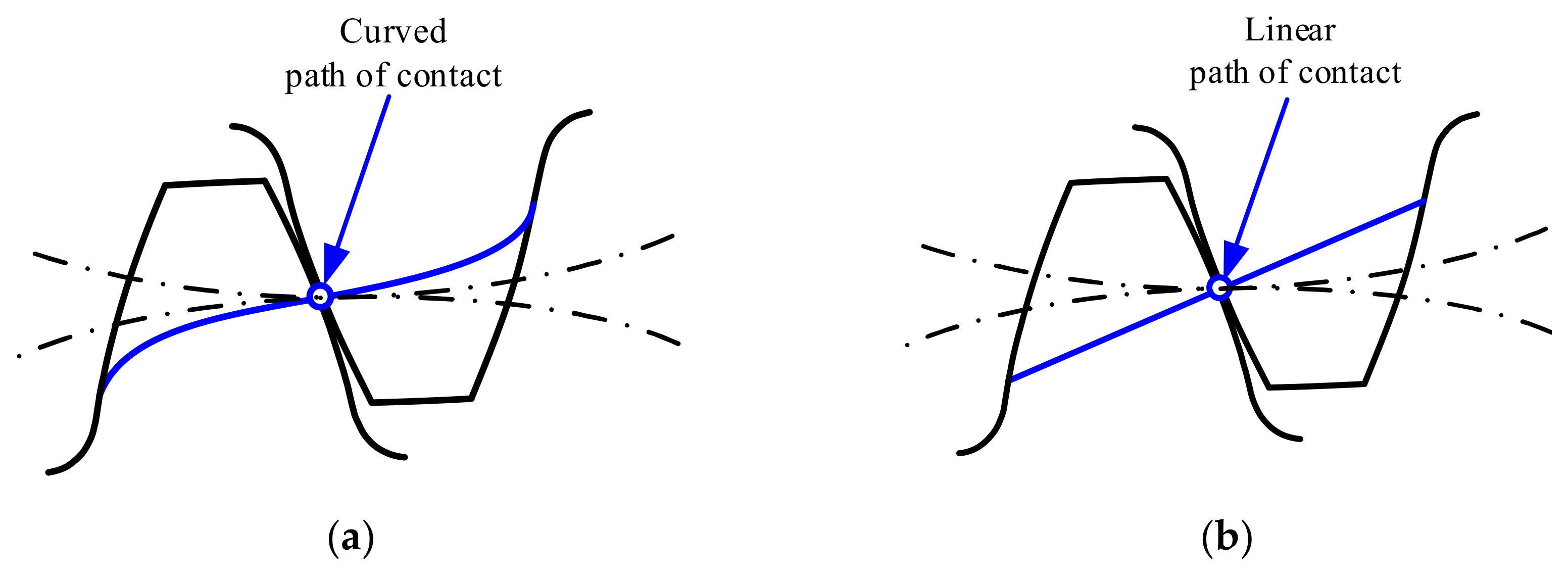
2. Designation of the Tooth Profiles Based on a Curved Path of Contact

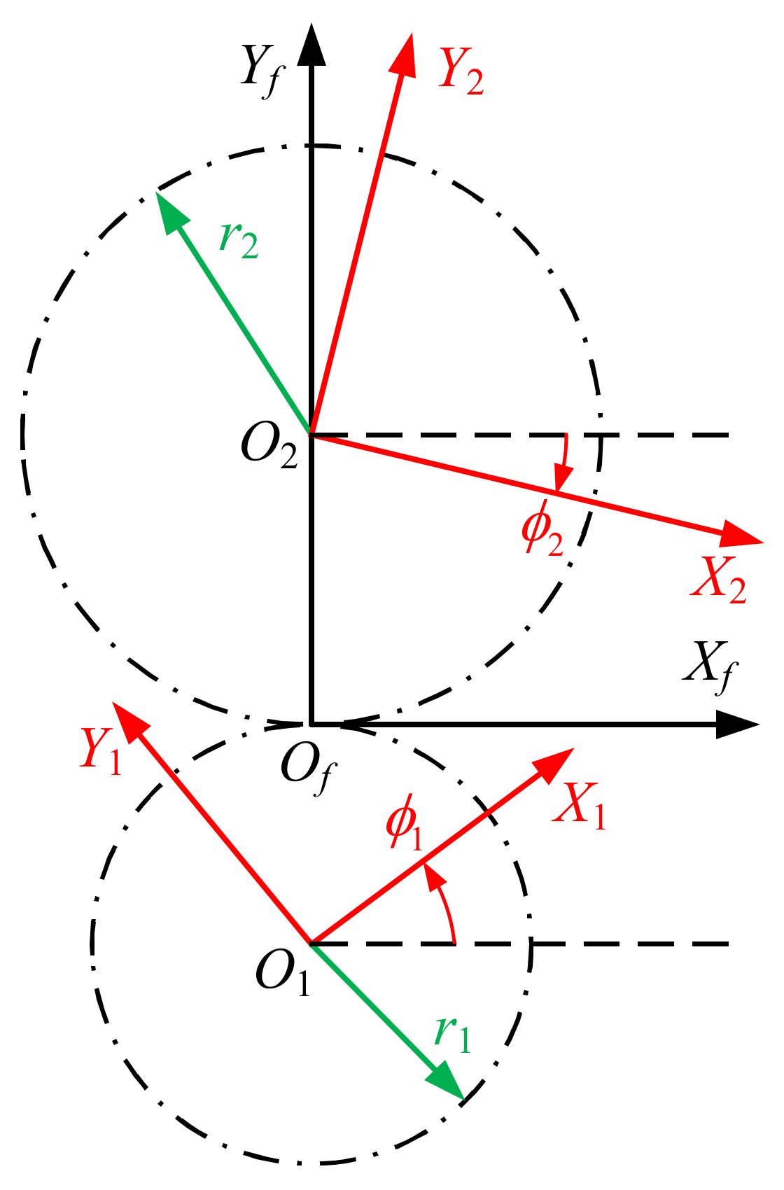
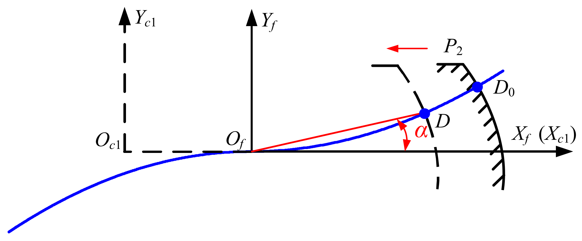
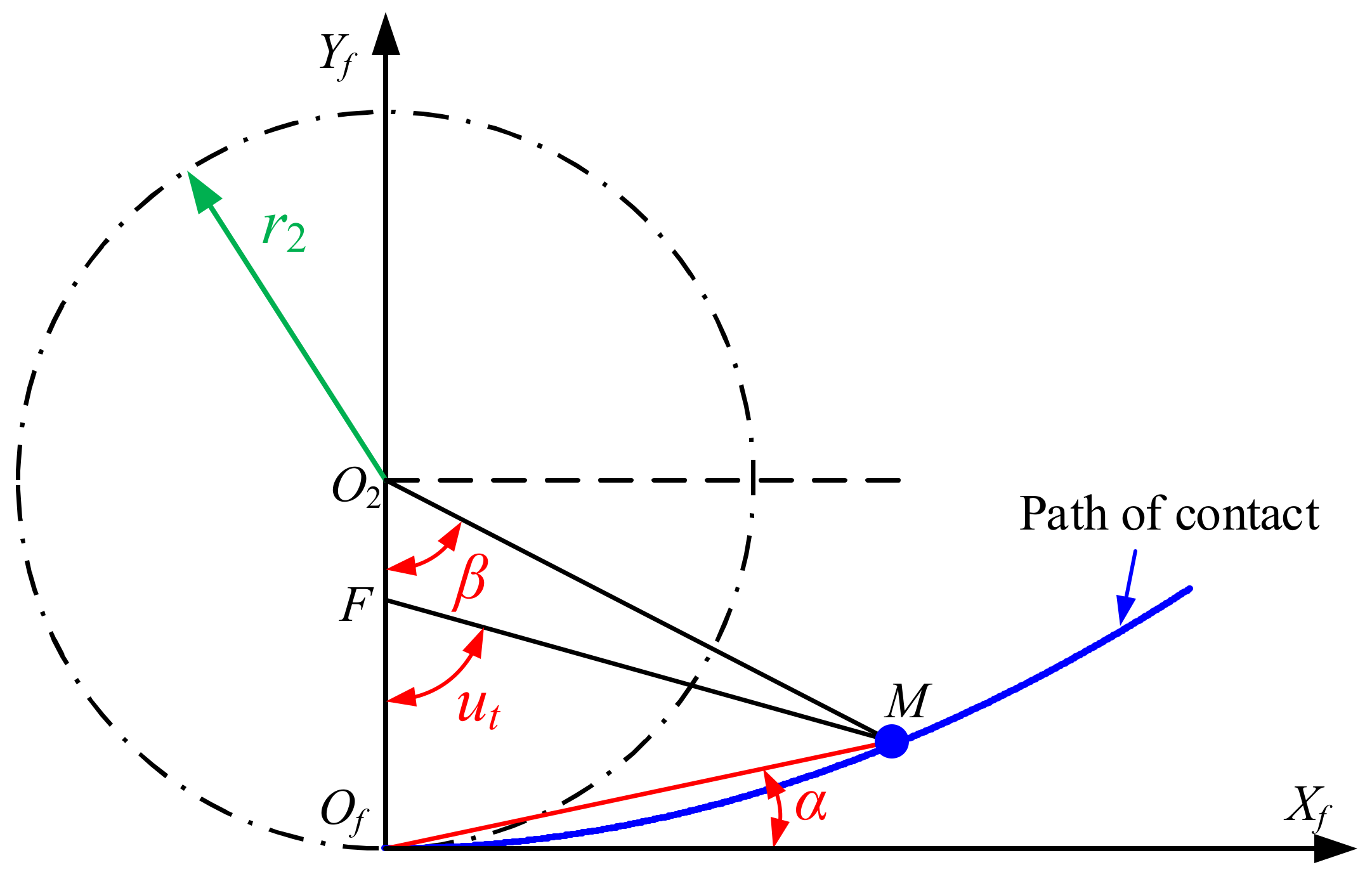
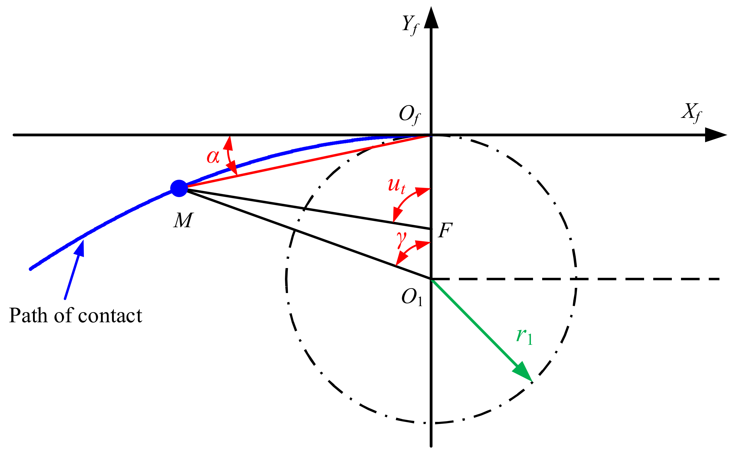
2.1. Mathematical Model of the Tooth Profiles Based on Path of Contact

When the gears rotate, the trajectory formed by the contact points in the fixed coordinate system Sf is the path of contact. The tooth profile curvature, sliding ratio, and contact ratio of the cylindrical gears can be calculated based on the path of contact. Therefore, the path of contact can be predesigned according to the performance that the gears need to meet. Essentially, the trajectory line in the coordinate systems of gears Si (i = 1, 2) when the contact point moves along the predesigned path of contact is the conjugate profile satisfying the performance. The detailed design of the conjugate tooth profiles of gears based on path of contact is described below.
As shown in Figure 2, the coordinate systems Si (i = 1, 2) and Sf are established, where Si (i = 1, 2) is the coordinate system fixed with pinion and gear, respectively, and the origins Oi (i = 1, 2) of the coordinate system are located at the center of the gears, respectively; Sf is the fixed coordinate system, and the origin Of of the coordinate system Sf is located at the tangent point of the pitch circles of the pinion and gear.
The position vector of the predesigned path of contact in the coordinate system Sf can be expressed by Equation (1):
r f = x f u t y f u t 1
where ut is the parameter of the predesigned line-of-contact path.
The pinion tooth profile r 1 that satisfies the predesigned path of contact can be obtained via Equation (2) according to the gear meshing theory [35]:
r 1 = L 1 , f r f
where L 1 , f is the coordinate transformation matrix from the coordinate system Sf to S1, obtained via Equation (3):
L 1 , f = cos ϕ 1 ( u t ) sin ϕ 1 ( u t ) r 1 sin ϕ 1 ( u t ) sin ϕ 1 ( u t ) cos ϕ 1 ( u t ) r 1 cos ϕ 1 ( u t ) 0 0 1
where ϕ 1 is the rotation angle of the pinion in the coordinate system S1, and r1 is the pitch circle radius of the pinion, as shown in Figure 2.
Therefore, the pinion tooth profile r 1 , described as the locus of the point on the path of contact represented in coordinate system S1, can be determined by Equation (4):
r 1 ( u t ) = x f ( u t ) cos ϕ 1 ( u t ) + y f ( u t ) sin ϕ 1 ( u t ) + r 1 sin ϕ 1 ( u t ) x f ( u t ) sin ϕ 1 ( u t ) + y f ( u t ) cos ϕ 1 ( u t ) + r 1 cos ϕ 1 ( u t ) 1
Similarly, the gear tooth profile r 2 , satisfying the predesigned path of contact, can be obtained via Equation (5):
r 2 ( u t ) = L 2 , f r f = x f ( u t ) cos ϕ 2 ( u t ) y f ( u t ) sin ϕ 2 ( u t ) + r 2 sin ϕ 2 ( u t ) x f ( u t ) sin ϕ 2 ( u t ) + y f ( u t ) cos ϕ 2 ( u t ) r 2 cos ϕ 2 ( u t ) 1
where L 2 , f is the coordinate transformation matrix from the coordinate system Sf to S2; ϕ 2 is the rotation angle of the gear in the coordinate system S2, and it should be noted that the rotation angle of gears ϕ i (i = 1, 2) meets the transmission ratio relationship. r2 is the pitch circle of the gear, as shown in Figure 2.
According to meshing theory, the normal vector at the instantaneous contact point must pass through the instantaneous center Of when the conjugate gears are engaged. Therefore, the unit normal vector of tooth surface in coordinate system Sf can be expressed by Equation (6):
n f = 1 ( x f ) 2 + ( y f ) 2 x f y f 0
The unit normal vector in coordinate system S1 is determined via Equation (7):
n 1 = L 1 , f n f = 1 ( x f ) 2 + ( y f ) 2 x f cos ϕ 1 ( u t ) + y f sin ϕ 1 ( u t ) x f sin ϕ 1 ( u t ) + y f cos ϕ 1 ( u t ) 0
The equation of meshing of the pinion is determined via Equation (8):
f 1 = n 1 d r 1 d u t d u t d t = x f x f + y f y f + r 1 x f ϕ 1 ( u t ) = 0
From Equation (8), we can obtain
ϕ 1 ( u t ) = x f x f + y f y f r 1 x f
By integrating Equation (9), the pinion rotation angle can be determined via Equation (10):
ϕ 1 ( u t ) = 0 u t x f x f + y f y f r 1 x f d u t
The gear transmission ratio is given and represented by the ratio of the tooth number of the gears via Equation (11):
m 12 = N 2 N 1 = ϕ 1 ϕ 2
where N1 and N2 are the tooth numbers of the pinion and gear, respectively.
Then, the gear rotation angle is determined based on the pinion rotation angle and the transmission ratio via Equation (12):
ϕ 2 ( u t ) = ϕ 1 ( u t ) m 12
Finally, by substituting Equations (10) and (12) into Equation (4) and Equation (5), the conjugate tooth profiles defined by the predesigned path of contact can be obtained.

2.2. Checking Tooth Undercutting

If the tooth undercutting occurs, the thickness of the tooth root becomes thinner, and the bending strength of the gear decreases; moreover, the contact ratio decreases, which greatly affects the stability of the transmission. Therefore, the condition of tooth undercutting should be checked during gear design.
According to the theory of gearing, undercutting will occur when the sliding velocity of the contact point on the tooth is equal to zero at singular points [26,36]. Therefore, the condition of undercutting can be expressed as the zero-sliding velocity of the tooth contact point.
Undercutting of the pinion is derived via Equation (13) [36]:
v r 1 v r 1 = 0
where v r 1 is the sliding velocity of the contact point on the pinion tooth, which can be represented as Equation (14):
v r 1 = d r 1 d t = d r 1 d u t d u t d t
Equation (15) is obtained by substituting Equations (4), (10), and (14) into Equation (13):
1 + m 12 x f x f + 1 + m 12 y f + r 1 + r 2 y f = 0
Similarly, the sliding velocity of the contact point on the gear tooth can be represented via Equation (16):
v r 2 = d r 2 d t = d r 2 d u t d u t d t
Undercutting of the gear is derived via Equation (17):
v r 2 v r 2 = 0
Equation (18) is obtained by substituting Equations (5), (12), and (16) into Equation (17):
1 + m 12 x f x f + y f + m 12 y f r 1 + r 2 y f = 0

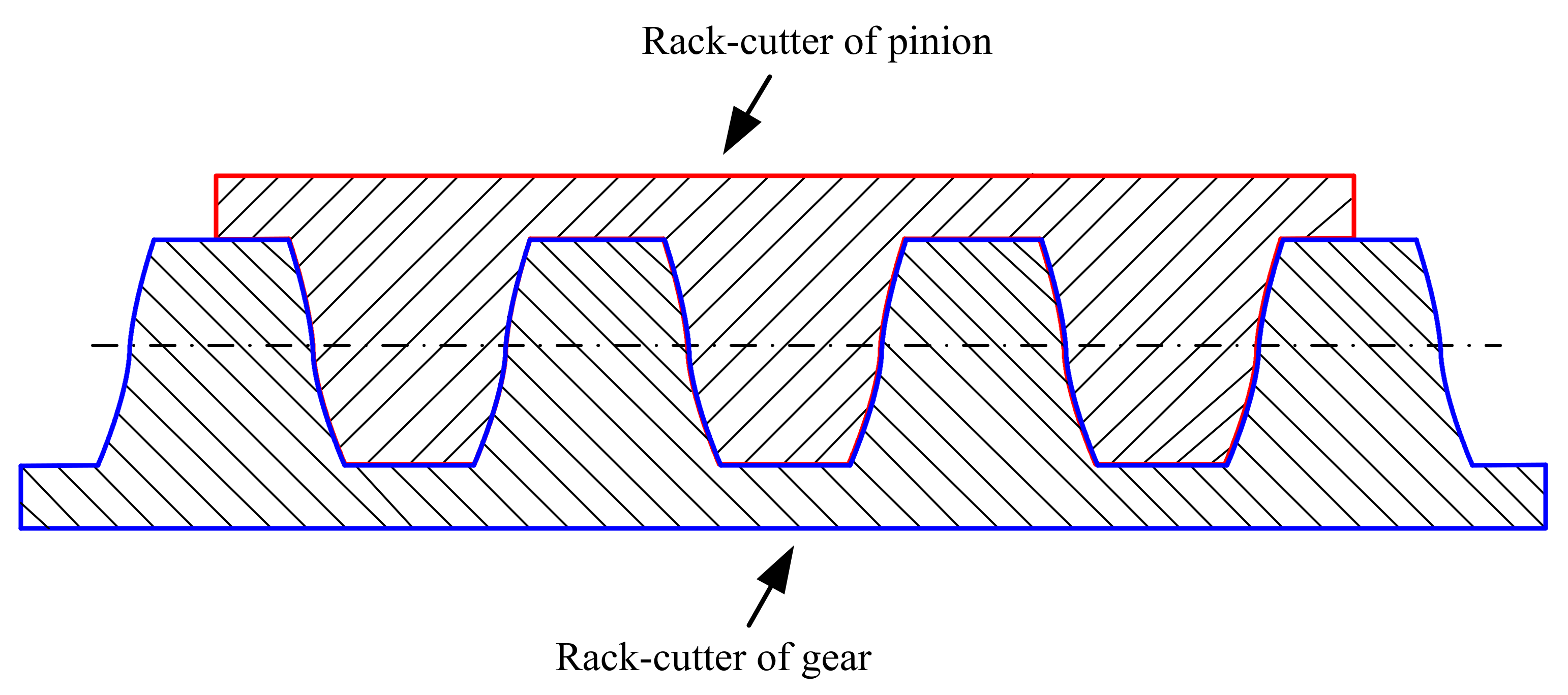
2.3. Determination of the Rack-Cutter Tooth Profile

In order to achieve the manufacturing of newly designed gears, the tooth profiles of the rack-cutter need be derived.
As shown in Figure 3, the curve P1P2 is the predesigned path of contact; the coordinate system Sc1 is established, which is the coordinate system fixed with the moving rack-cutter, and the coordinate axis Xc1 is coincident with the pitch line of the rack-cutter.
At the initial position, the moving coordinate system Sc1 is coincident with the fixed coordinate system Sf. The tooth profile of the rack-cutter intersects contact path P1P2 at point D0. Then, with the rack-cutter moving, the rack-cutter and the curve P1P2 intersect at point D, and we can obtain
tan α = y f x f
where α is the intersection angle between the coordinate axis Xf and line OfD; (xf, yf) are the coordinates of point D in coordinate system Sf.
According to gear meshing theory, it can be known that the tangent at the point D of the rack-cutter profile must be perpendicular to OfD, and we can obtain
d y c 1 d x c 1 = cot α
where (xc1, yc1) are the coordinates of point D in coordinate system Sc1.
Then, Equation (21) can be obtained from Equations (19) and (20):
d x c 1 = y f x f d y c 1
Meanwhile, since the y-axis coordinate of point D in coordinate system Sf is equal to the y-axis coordinate in coordinate system Sc1, Equation (22) is obtained:
d x c 1 = y f x f d y f
Thus, the tooth profile of the rack-cutter is determined based on the path of contact via Equation (23):
x c 1 = y f x f d y f + Δ y c 1 = y f
where Δ is the integral constant, which can be determined based on the starting position of the rack-cutter.
Referring back to Equation (1), Equation (23) can be rewritten as follows:
x c 1 u t = 0 u t y f u t x f u t y f u t d u t + Δ y c 1 u t = y f u t
According to the above method, the tooth profile of the rack-cutter for the pinion (one half of the gear pair) can be obtained. The tooth profile of the rack-cutter for the gear (the other half of the gear pair) can be determined based on the tooth profile of the rack-cutter for the pinion via Equation (25):
x c 2 u t =   cos π x c 1 u t + sin π y c 1 u t y c 2 u t =   sin π x c 1 u t + cos π y c 1 u t

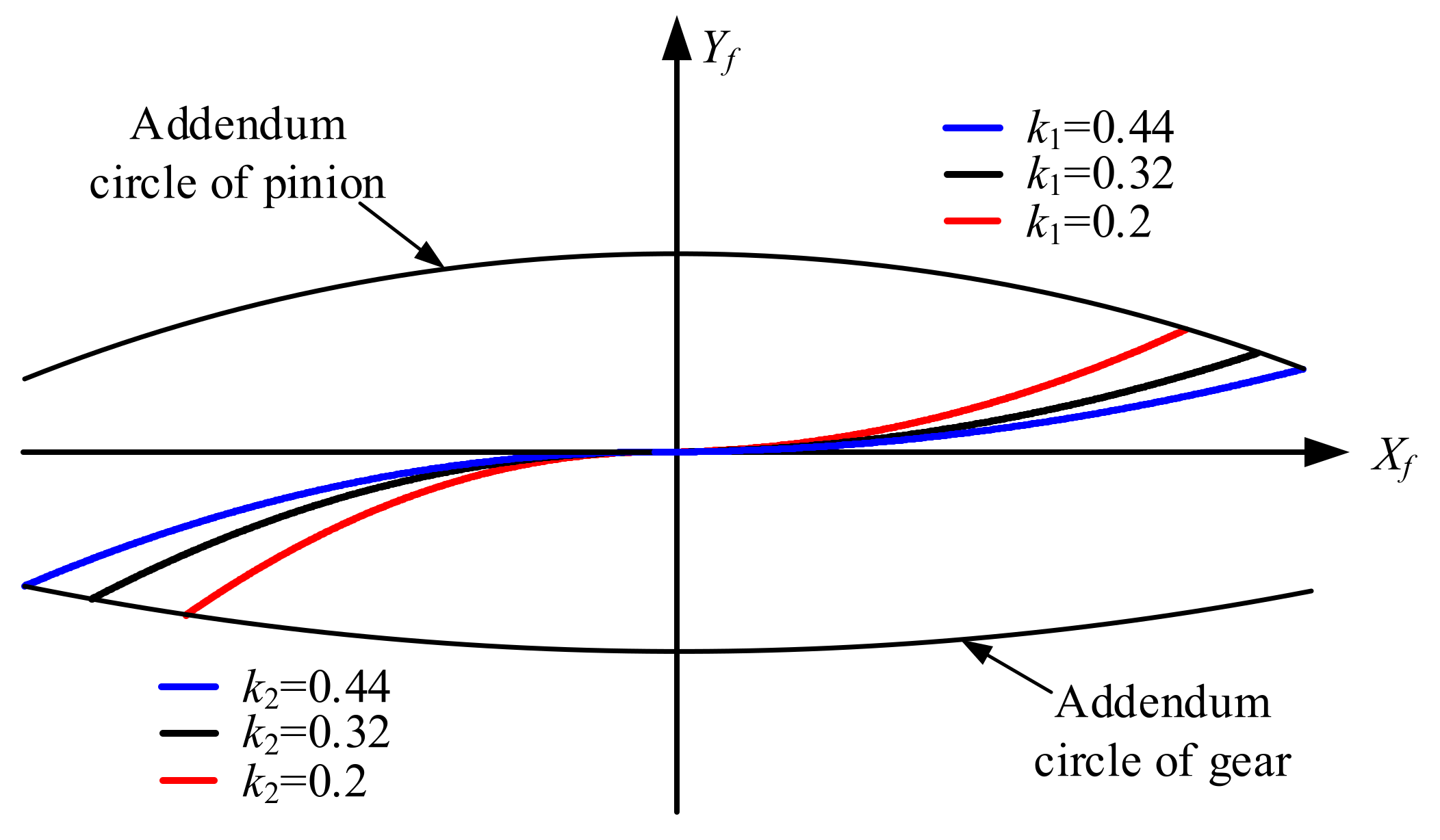
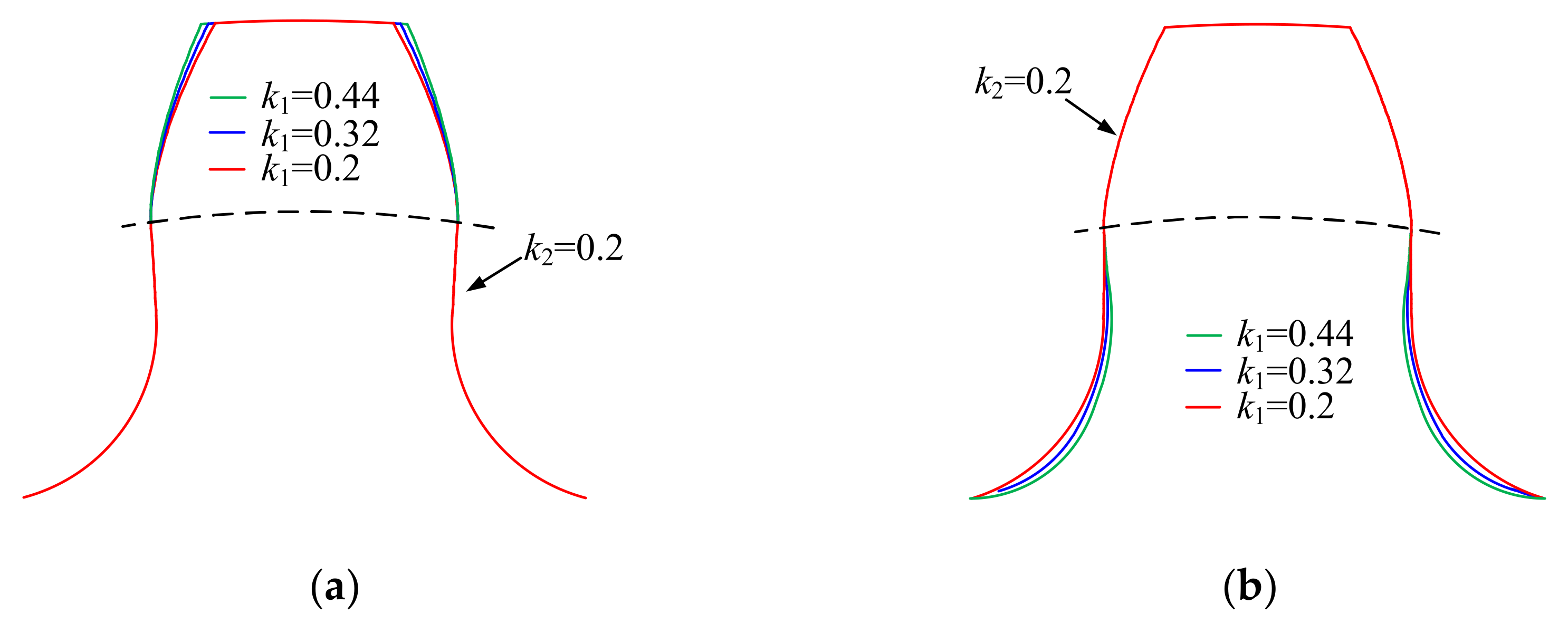
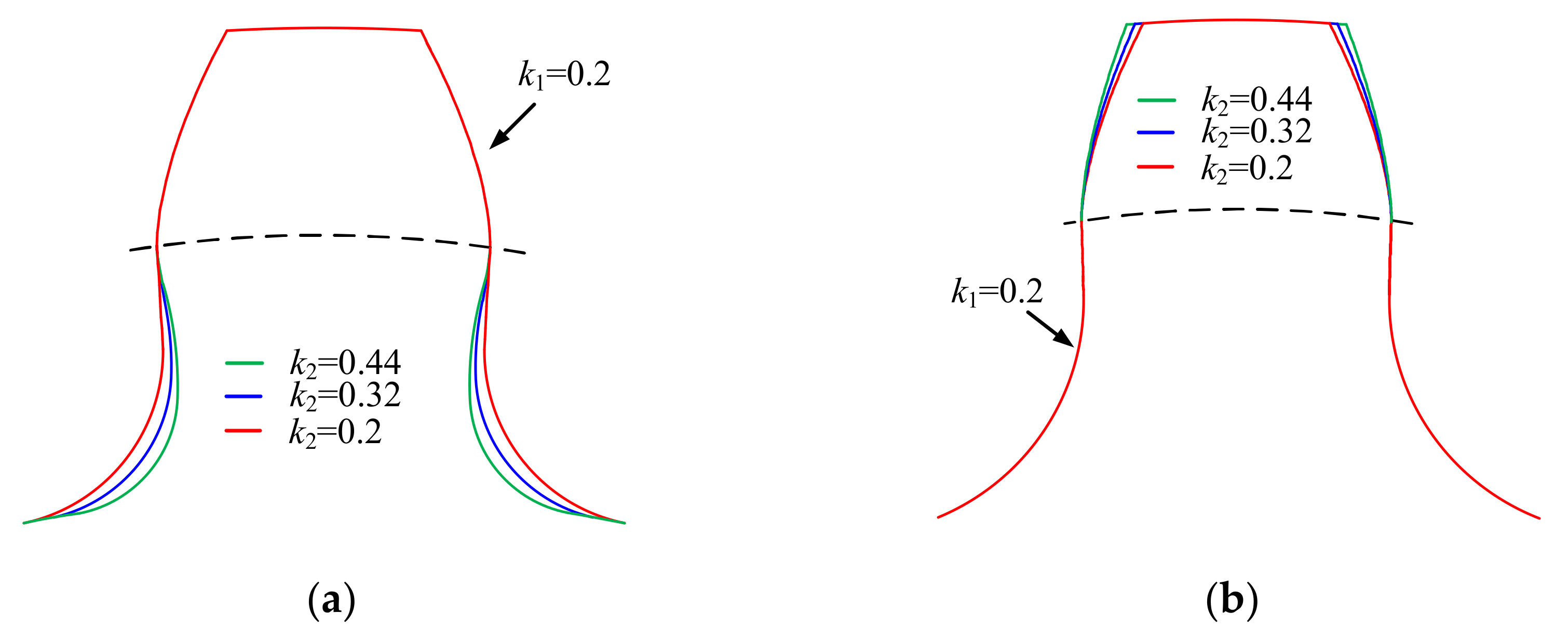
2.4. Design of Tooth Profiles Based on Parabolic Path of Contact

As shown in Figure 4, the path of contact at the first quadrant of gears is predesigned as a parabolic curve via Equation (26):
x f = 2 p 1 t y f = 2 p 1 t 2 p 1 > 0 , t 0
where the vertex of the parabolic curve is at Of (0, 0) and the focus is at the point F (0, p1/2), and t is the parameter of the parabolic curve.
Connecting Of with the moving point M on the path of contact, and defining the angle between Of M and the Xf-axis as α, Equation (26) can be expressed as:
x f = 2 p 1 cot α y f = 2 p 1 ( cot α ) 2 0 < α < π 2
If α = 0, the following relationship exists for Equation (27):
x f =   0 y f =   0
It is assumed that the parameter r′ is a dimensionless parameter, and it is defined as r′ = p1/2 = k1r2. Then, Equation (28) can be obtained:
k 1 = p 1 2 r 2
In Figure 4, according to the geometric relation of triangle OfMF, we can obtain
O f M ¯ sin u t = M F ¯ sin π 2 α
where M F ¯ represents the distance between the focus of the parabolic curve and the moving point M, and O f M ¯ represents the distance between the vertex Of of the parabolic curve and the point M. M F ¯ and O f M ¯ have the following relationships with the parabola, respectively:
M F ¯ = y f + p 1 2
O f M ¯ = ( x f ) 2 + y f 2
Incorporating Equations (27), (31), and (32) into Equation (30), the relationship between the parameters ut and α can be obtained:
cot α = 1 2 sin u t 1 sin u t
Substituting Equation (33) into Equation (27) gives the parabolic curve equation at the first quadrant using ut as the parameter:
x f =   p 1 sin u t 1 sin u t y f =   p 1 sin u t 2 1 sin u t
where the range of ut can be defined as 0 < ut < π.
Similarly, as shown in Figure 5, the path of contact at the third quadrant of the new gears can be expressed as:
x f =   p 2 sin u t 1 sin u t y f =   p 2 sin u t 2 1 sin u t
where the vertex of the parabola is at Of (0, 0) and the focus is at the point F (0, −p2/2).
It is assumed that the parameter r″ is a dimensionless parameter, and it is defined as r″ = p2/2 = k2r1. Then, Equation (36) can be obtained:
k 2 = p 2 2 r 1
Substituting Equations (5), (29), and (34) into Equation (18), the critical condition of undercutting of the gear can be obtained as:
u t = sin 1 1 2 k 1 1 k 1
According to the theory of gear meshing, it is necessary to ensure that the contact ratio of the gears is greater than 1 for a smooth transmission. When the moving point M is located in the path of contact at the first quadrant, the angle β should be greater than the angle corresponding to a quarter of a tooth of the gear, so the range of the parameter β can be expressed as
π 2 z 2 < β u t
As shown in Figure 4, according to the geometric relation of triangle O2MF, we can obtain
M F ¯ sin β = O 2 M ¯ sin π u t
O 2 M ¯ = x f 2 + r 2 y f 2
Substituting Equations (31), (34), and (40) into Equation (39), we have
β = sin 1 1 2 k 1 k 1 1 k 1 2 k 1 1 k 1
Substituting Equations (37) and (41) into Equation (38), we can obtain the range of k1 without undercutting:
sin π 2 z 2 < 1 2 k 1 k 1 1 k 1 2 k 1 1 k 1 1 2 k 1 1 k 1
Similarly, substituting Equations (4), (35), and (36) into Equation (15), the critical condition of undercutting of the pinion can be obtained as
u t = sin 1 1 2 k 2 1 k 2
The range of k2 without undercutting can be obtained via the same method:
sin π 2 z 1 < 1 2 k 2 k 2 1 k 2 2 k 2 1 k 2 1 2 k 2 1 k 2

3. Error-Sensitivity Analysis and Tooth Modification

Errors are unavoidable in practical working conditions. Tooth modification has been proved to be the most economical and effective technique to reduce the effect of errors. To some extent, tooth modification is essential for gears. Therefore, the effects of errors and tooth modification on the meshing performance of the presented novel gears need to be comprehensively analyzed.
In this paper, the geometry of the shape of the tooth profile is determined by the parameters of the curve of the contact path. Therefore, the tooth modification mainly refers to the longitudinal modification of the tooth herein.

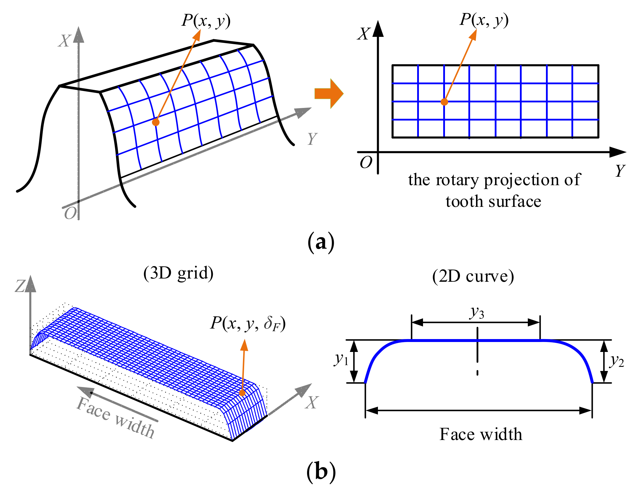
3.1. Three-Dimensional (3D) Grid Modeling of the Novel Gear with Tooth Modification

An accurate 3D model is the key to analyzing the meshing preference of gears. An accurate 3D model of an unmodified gear is obtained based on the rack-cutter and the motion relationship between the rack-cutter and the machined gear.
The simulation program for the gear generation process was written based on MATLAB. The main steps of modeling were as follows:
(1)
The coordinates of the instantaneous cutting points of the rack-cutter from entering engagement to exiting engagement were solved by using gear meshing theory.
(2)
The plane node coordinates of the tooth profiles on both sides of the tooth were determined by rotating projection transformation.
(3)
Similarly, the plane node coordinates of the gear tooth base can also be obtained by rotating projection transformation.
(4)
All the spatial joint coordinates of a gear tooth were calculated based on the plane node coordinates using coordinate transformation along the longitudinal direction.
(5)
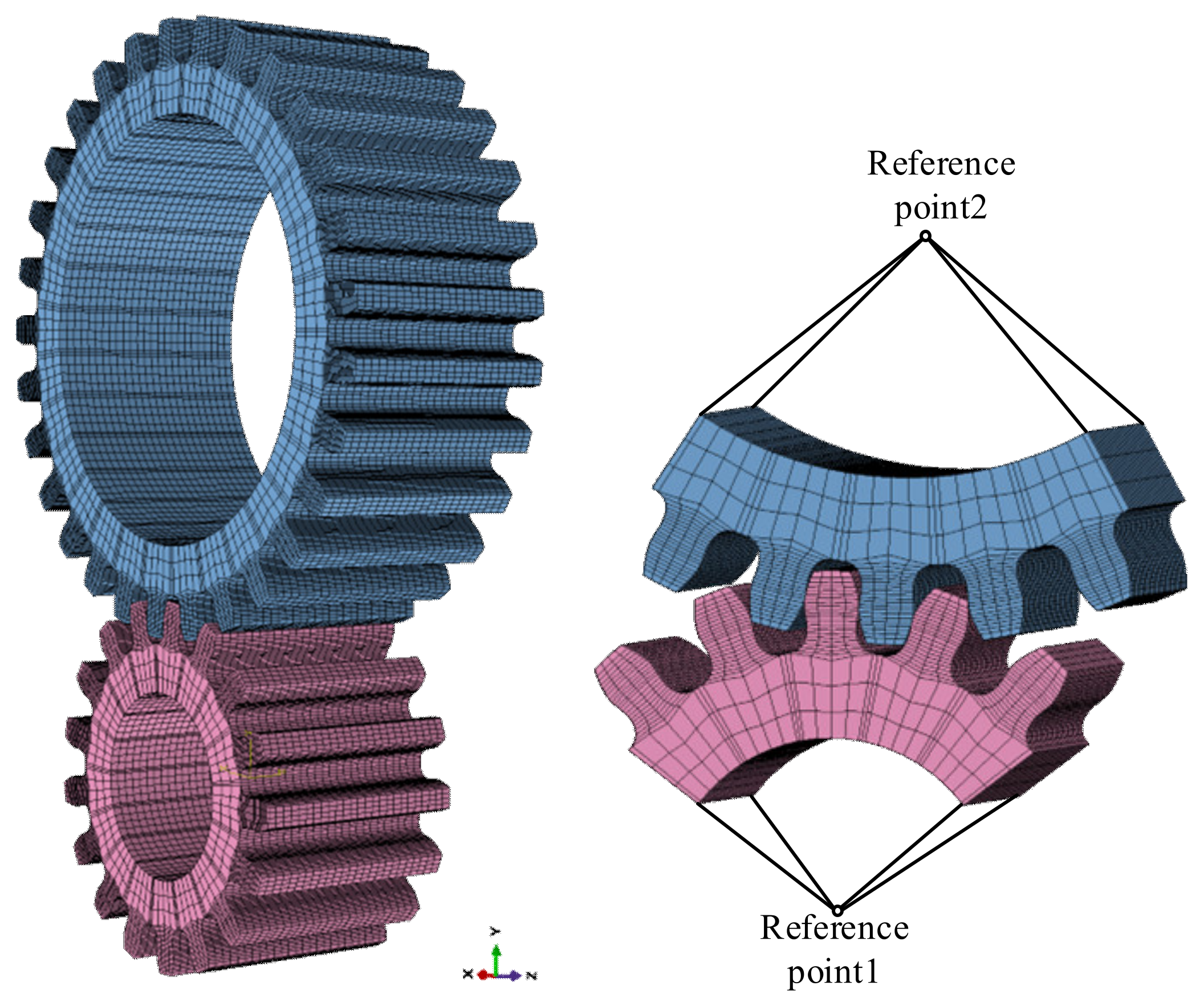
The calculated node coordinate file was imported into ABAQUS to realize rapid 3D modeling of the novel gear.
It should be noted that if the gear is helical, an additional rotation coordinate transformation is required in step (4) above.
After modeling of the unmodified gears is completed, modeling of the modified gears can be carried out on the unmodified ones.
As shown in Figure 6, the modified tooth is composed of an unmodified tooth and the surface of the modified value. The surface of the modified value is obtained based on a 2D modification curve designed for the longitudinal modification. The 2D modification curve is composed of two second-order parabolic curves and a straight line, where y1 and y2 are the maximum modification values; y3 is the unmodified length in the direction of tooth width. Then, gridding is performed on the rotating projection surface of the unmodified gear and the surface of the modified value. In Figure 6a, point P (x, y) is one node on the grid of the tooth surface. In Figure 6b, the modified value δF of the node P (x, y) can be determined based on the 2D modification curve. After that, the coordinates of the space nodes of the unmodified gear are adjusted according to the modified values. Finally, the calculated node coordinate file for the modified gear is imported into ABAQUS to realize rapid 3D modeling.
The developed calculating program can realize the parameterized modeling of the modified gear. The 3D grid model of the modified gear derived from this program is shown in Figure 7. Based on the 3D grid model, the loaded-tooth contact analysis of the novel gears can be carried out.
In the following finite element analysis, the Young’s modulus of the gear material is 2.01 × 10⁵ MPa; the Poisson’s ratio is 0.29. No friction between contacting teeth is assumed.

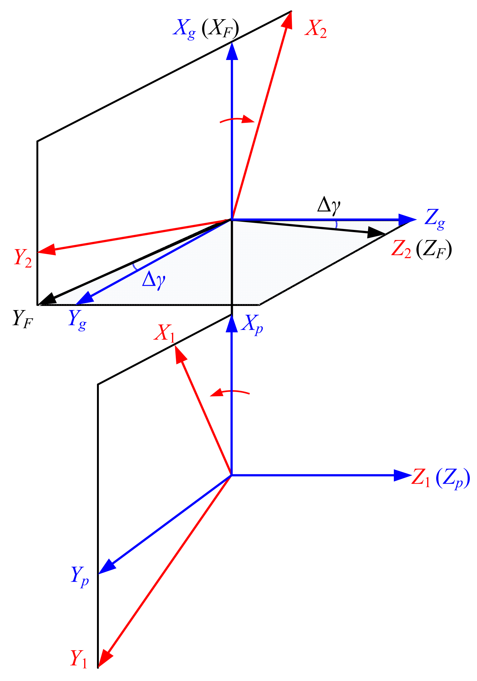
3.2. Error-Sensitivity Analysis

As shown in Figure 8, the misalignment error Δγ is added to the rotating coordinate system to analyze the effect of the errors on the performance of the given novel gears. The coordinate system Sg is the coordinate system of the gear without misalignment error, the coordinate system SF is the fixed coordinate system with misalignment error, and the gears rotate around the coordinate axis Z2. The rotation matrices from systems Sg to SF for misalignment error are represented in the following:
L g , F = 1 0 0 0 cos Δ γ sin Δ γ 0 sin Δ γ cos Δ γ
where L g , F is the coordinate transformation matrix from coordinate systems Sg to SF, obtained via Equation (45).

4. Results

The proposed design method is verified via an example in Table 1. The performance of the given novel non-involute gears is studied and compared with the involute gears. A torque of 134 Nm is applied to the pinion. The engagement process from tooth contact to tooth leave is discretized, and the step is 1 degree. The 0° position is set at the position where the gears engage at the pitch point.

4.1. Design of the Novel Gears

Based on the parameters of the novel gears in Table 1, it can be obtained that the ranges of parameters k1 and k2 without undercutting are 0.2 ≤ k1 < 0.473 and 0.2 ≤ k2 < 0.454, respectively. To study the effect of the parabolic parameters of the contact path on the tooth profile, some effective values of k1 and k2 are used to design the novel gears.
As shown in Figure 9, the path of contact is designed with different parameters, and the corresponding tooth profiles are given in Figure 10 and Figure 11, respectively. Figure 10 shows the effect of parameter k1 on the tooth profile of the novel gears. It can be seen that the tooth profiles of the addendum of the pinion and the dedendum of the gear are determined by the path of contact located in the first quadrant. The tooth thickness of the addendum of the pinion increases with the increase in the parabolic coefficient k1 at the first quadrant; at the same time, the gear’s dedendum tooth thickness decreases with the increase of the coefficient k1. Figure 11 gives the effect of parameter k2 on the tooth profile of the novel gears. It can be seen that the tooth profiles of the dedendum of the pinion and the addendum of the gear are determined by the path of contact located in the third quadrant. As the parabolic coefficient k2 increases, the tooth thickness of the dedendum of the pinion decreases, while the tooth thickness of the addendum of the gear shows the opposite trend.
Figure 12 shows the tooth profile of the rack-cutters of the novel pinion and gear. It can be seen that the rack-cutters for the pinion and the gear are different. The rack-cutters of the pinion and the gear can be embedded together. The addendum shape of the rack-cutter of the pinion is the same as the dedendum of the rack-cutter of the gear. Likewise, the dedendum shape of the rack-cutter of the pinion is the same as the addendum of the rack-cutter of the gear.

4.2. Loaded-Tooth Contact Analysis of the Novel Gears

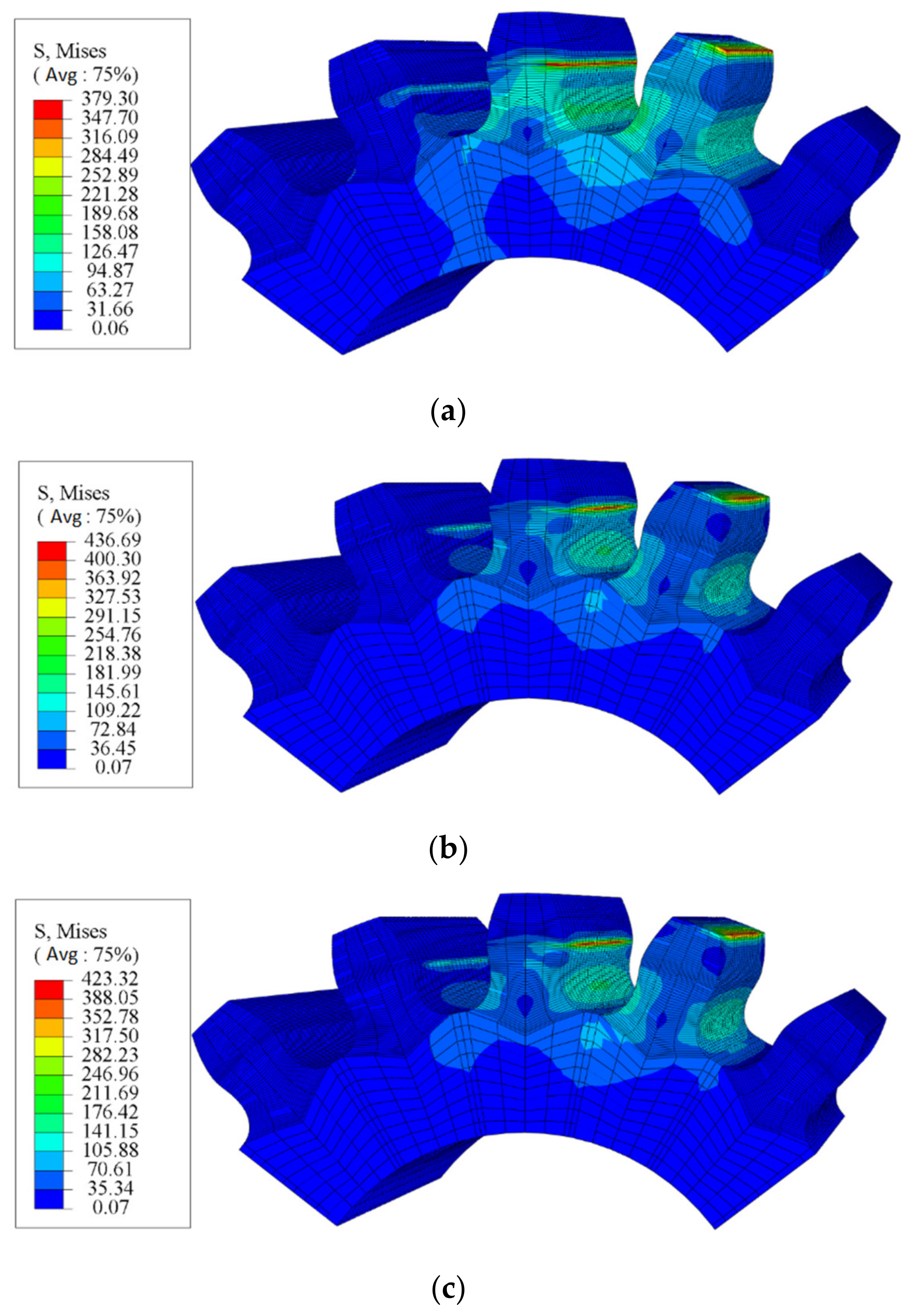
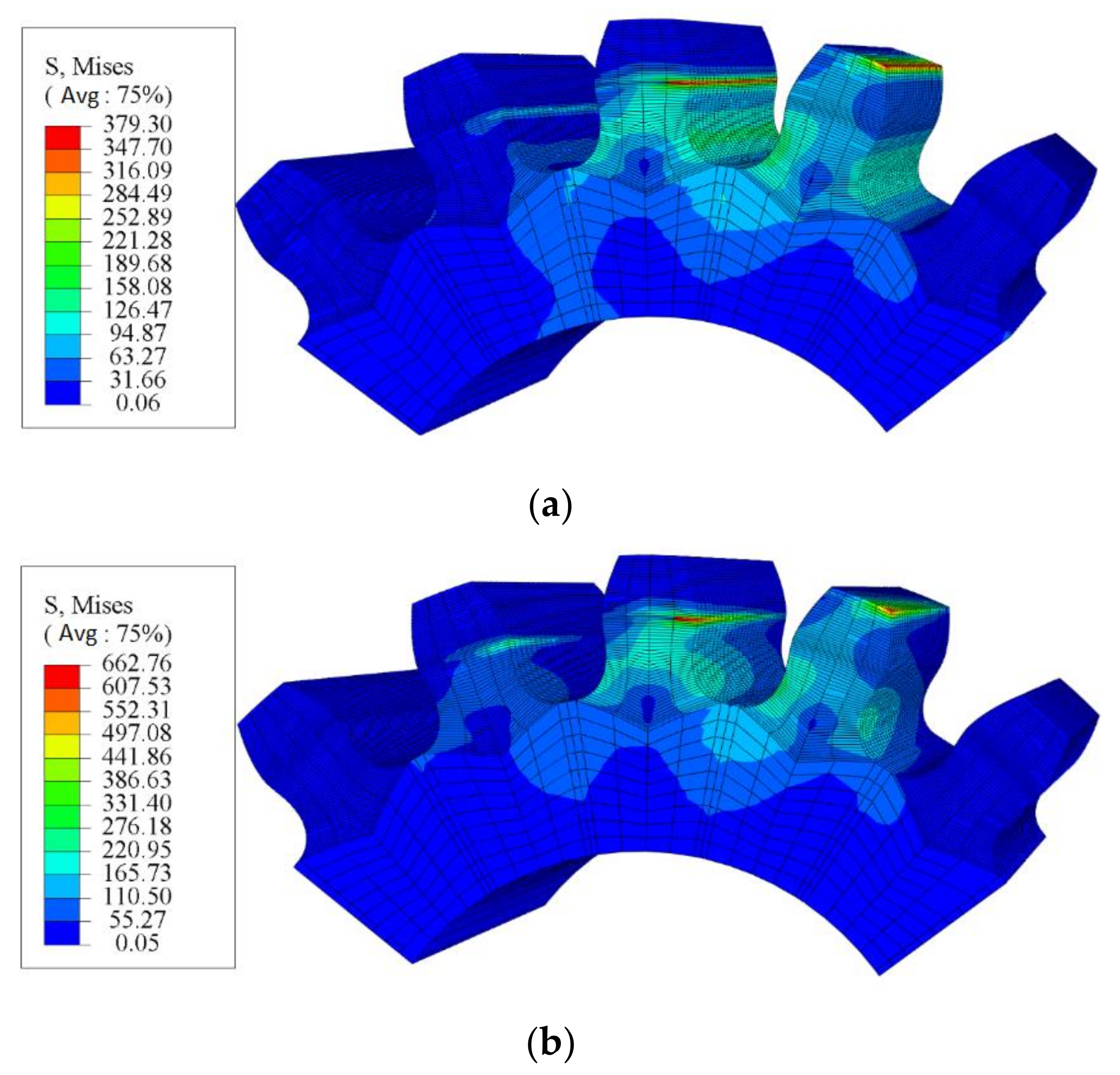
4.2.1. Verification of Finite Element Calculation Accuracy

Before the following finite element analysis, the accuracy of the finite element calculation results is verified by comparison with the classic Hertz formula calculation results.
A 3D grid model of the standard involute gears was used in the verification process herein. In this paper, the grid setting of the novel gear is the same as that of the involute gear. In the loaded-tooth contact analysis, the constraint conditions and the loads of the novel gear are also the same as those of the involute gear. Therefore, if the finite element calculation accuracy of the involute gear is sufficient, the new gear can also meet the requirements.
The accuracy of the finite element calculation was evaluated by comparing the contact stress at the pitch circle. The CPRESS stress calculated by finite element analysis was 1351.33 MPa, and the contact stress calculated by Hertz contact theory was 1427.49 MPa. The error between the finite element analysis and the theoretical calculation is 5.34%.

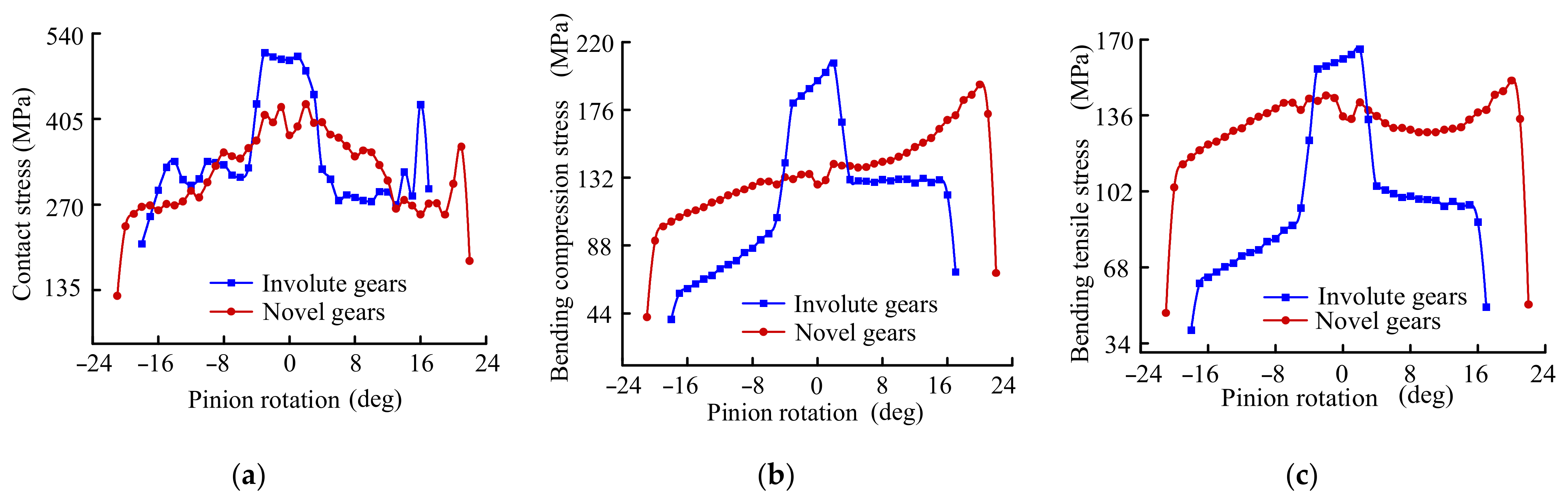
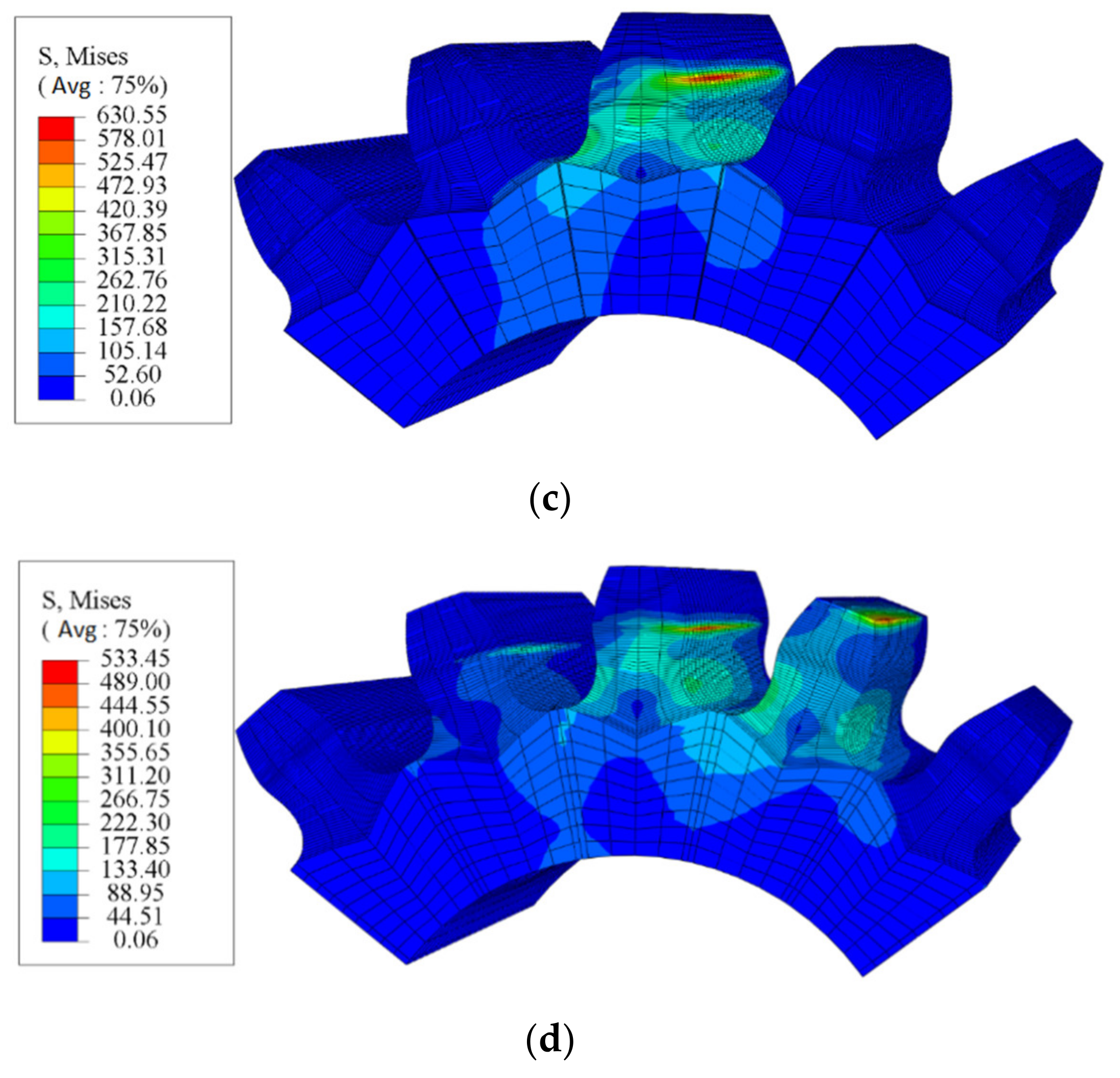
4.2.2. Load-Carrying Capacity Verification of the Novel Gears

In order to verify the load-carrying capacity of the presented novel gears, Figure 13 gives the comparison of their stress with that of the involute gears. It can be seen from Figure 13 that both the in-contact stress and bending stress of the novel gears are lesser than those of the involute gears. Moreover, it can be found that the maximum contact stress and the bending stress of the involute gears occur near the middle of the tooth surface; the maximum bending stress of the novel gears appears at the edge where the tooth is about to leave engagement. As shown in Table 2, the values of the maximum stress of the novel gears and the involute gears are given. Compared with the involute gears, the maximum contact stress is reduced by 16.10%, the maximum bending compressive stress by 6.75%, and the maximum bending tensile stress by 8.49%.

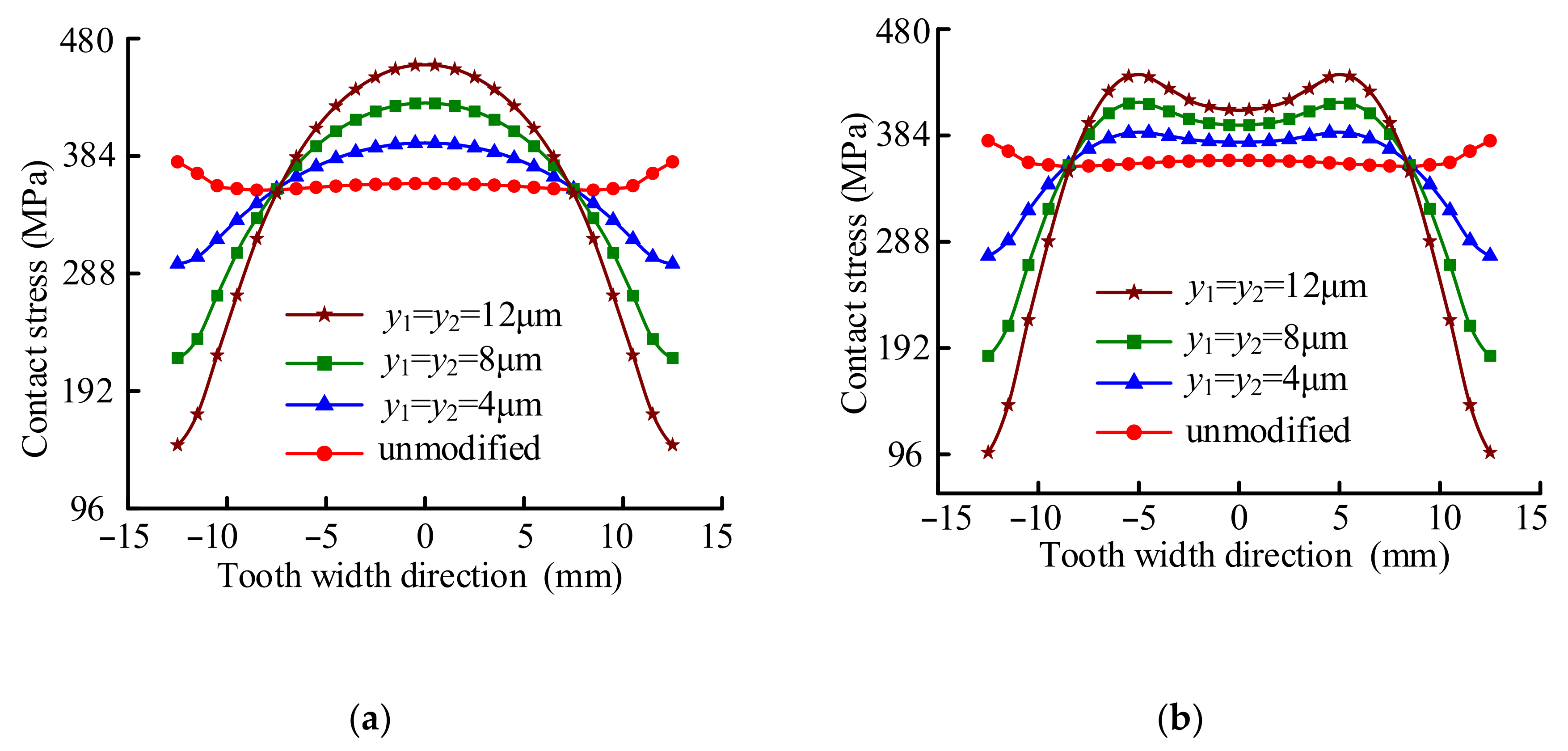
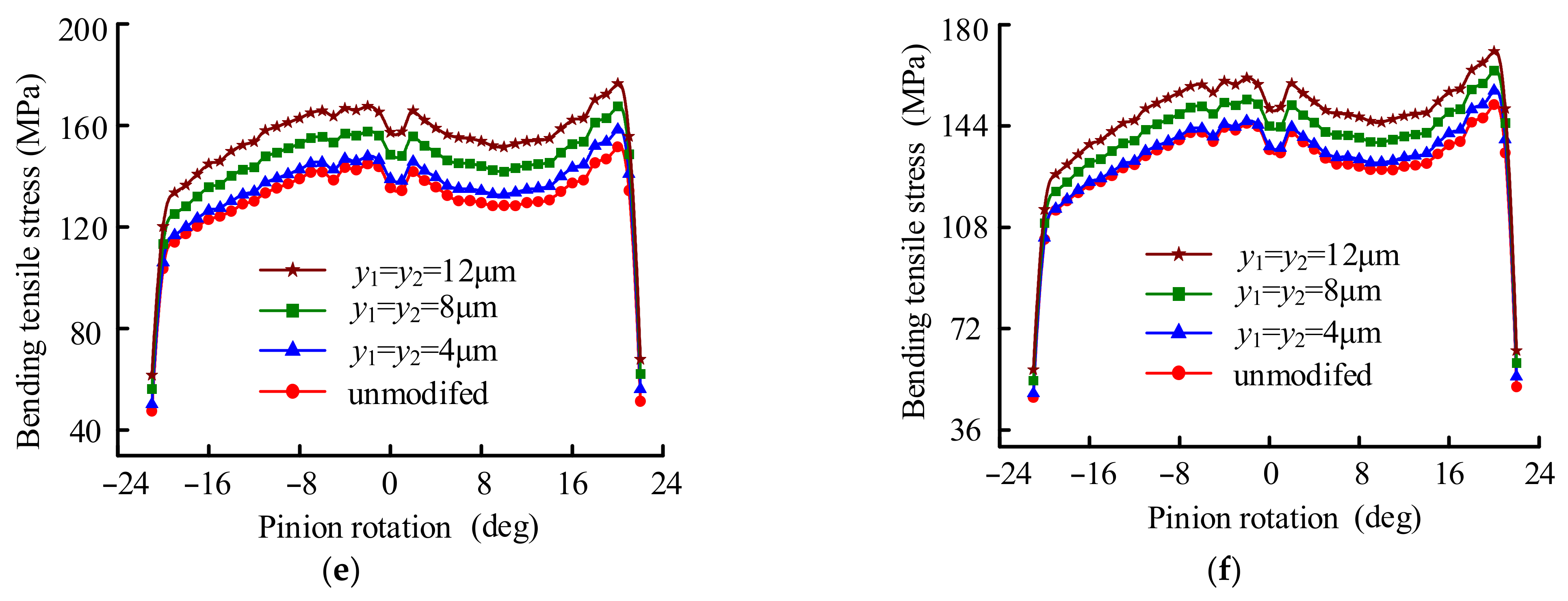
4.2.3. Tooth Modification of the Novel Gears

It is well-known that errors in assembly and manufacturing are unavoidable in actual working conditions. Tooth modification has been proved to be the most economical and effective technique to reduce the influence of errors. Therefore, a comprehensive analysis of the influence of tooth modification on the meshing performance of the novel gears is given below, and only the pinion is modified.
In Figure 6, the parameters of tooth modification are given. y1 and y2 are the maximum modification values of tooth width at both ends; y3 is the unmodified length in the direction of tooth width. In this section, six cases of tooth modification are designed to study the effect of tooth modification on the stress of the novel gears.
Tooth modification first changes the tooth surface load distribution, and then causes a change in stress. In order to study the influence of tooth modification on the tooth surface load distribution, Figure 14 gives the tooth surface load distribution of the novel gears at the pitch circle position. For the unmodified gear, the load on both ends of the tooth side is large due to the edge effect. For the modified example, it can be seen from Figure 14a that the load is concentrated in the middle of the tooth surface due to the tooth surface modification, which is beneficial to the gear transmission. However, it can also be found that with the increase in the tooth modification, the degree of load accumulation gradually increases, which may lead to local stress concentration and even reduce bearing capacity. In Figure 14b, y3 is set to 8 mm for comparison with Figure 14a. It can be seen that the change in y3 reduces the degree of load accumulation. Therefore, in practical application, the tooth modification parameters must be carefully designed. To observe the influence of tooth modification directly, Figure 15 demonstrates the contour map of the von Mises stresses of the unmodified novel gears and modified novel gears meshing at pitch point.
In order to further study the influence of tooth modification on the bearing capacity of the novel gears, Figure 16 shows the comparison of the stress of the novel gears with different values of tooth modification. As can be seen from Figure 16a,b, the contact stress of the novel gears increases with the increase in tooth modification value, because the load on the tooth surface gradually transfers from both sides of the tooth surface to the middle area of the tooth surface with the increase in the tooth modification value. It can also the observed that the position of maximum contact stress is approximately at the pitch circle position. As shown in Table 3, when y3 is 0, y1 and y2 are 4 μm, and the maximum contact stress is 448.62 MPa; when y3 remains unchanged and y1 and y2 increase to 12 μm, the maximum stress increases to 529.6 MPa, and the increase percentage is 18.05%. When y1 and y2 remain unchanged, equal to 8 μm, and y3 increases from 0 to 8 mm, the contact stress decreases by 1.32%.
Figure 16c–f give the variations of the bending compressive stress and the bending tensile stress with the tooth modification value, respectively. It can be seen that the variation trend of the bending compressive stress and the bending tensile stress with the rotation of the pinion are basically the same, and the maximum stress occurs in the area where the tooth is about to exit the mesh. As shown in Table 3, when y3 remains unchanged, equal to 0, and y1 and y2 increase from 4 μm to 12 μm, the maximum bending compressive stress and maximum bending tensile stress increase by 12.19% and 11.43%, respectively; when y1 and y2 remain unchanged, equal to 8 μm, and y3 increases from 0 to 8 mm, the maximum bending compressive stress and maximum bending tensile stress decrease by 2.87% and 2.32%, respectively.

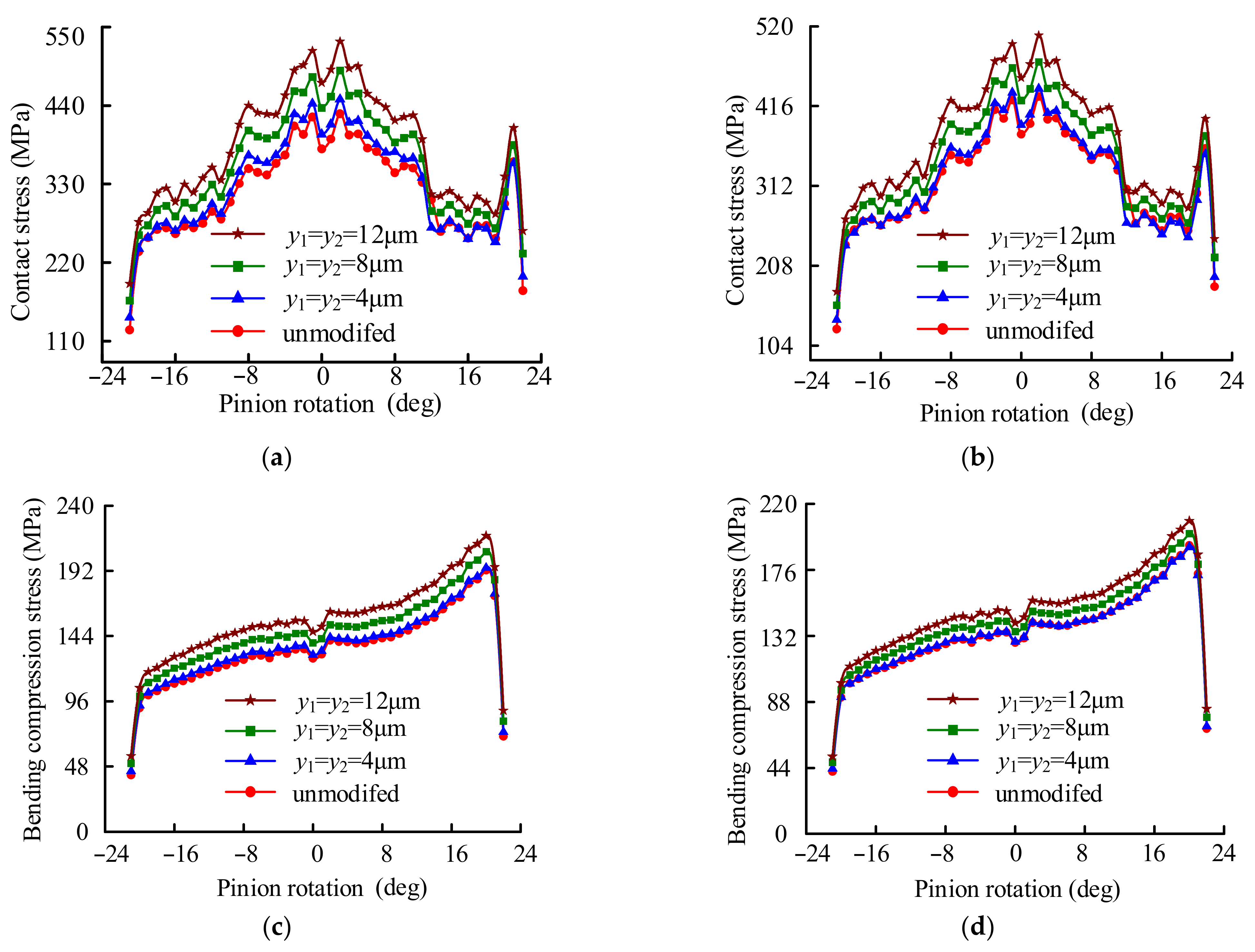
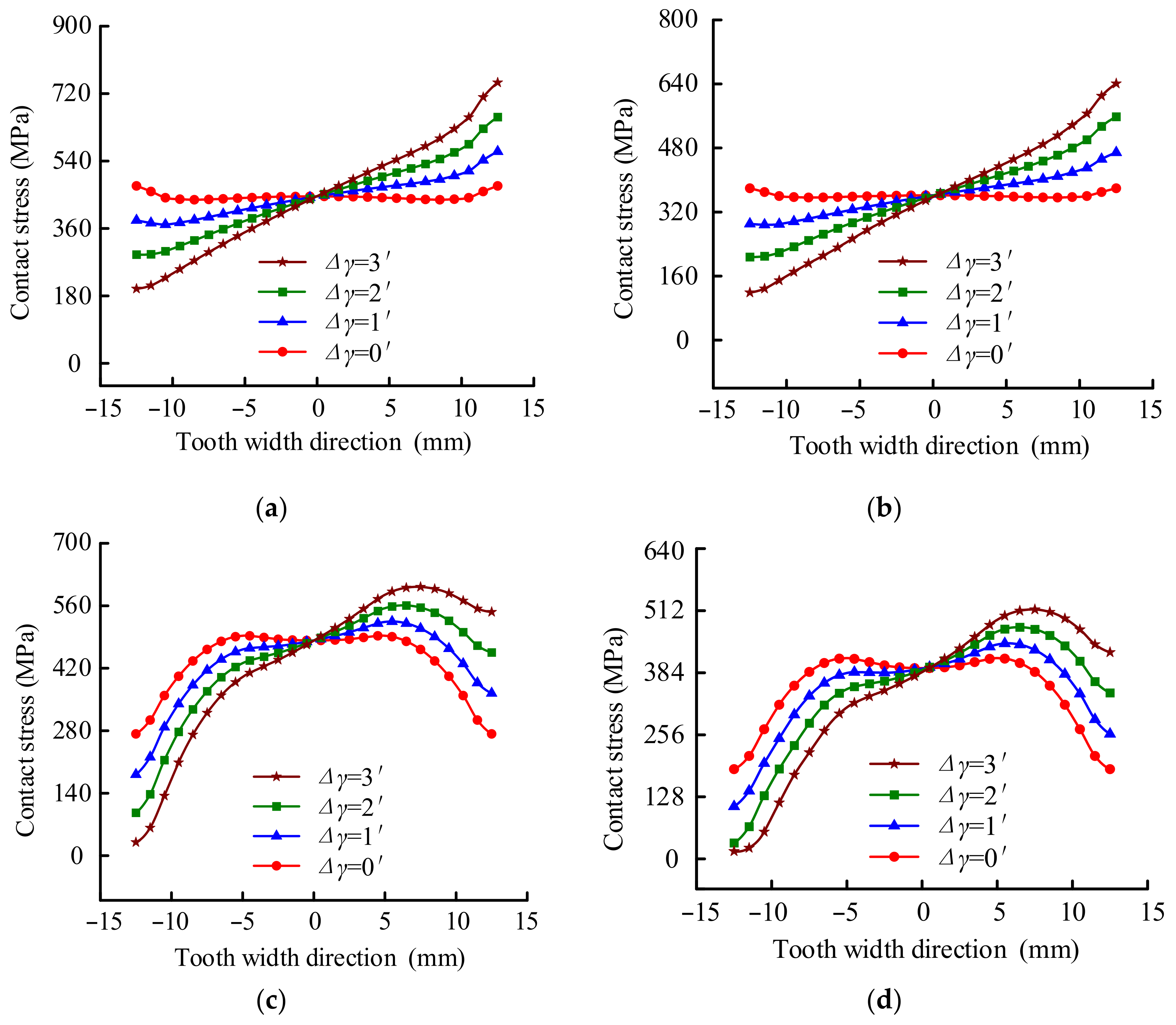
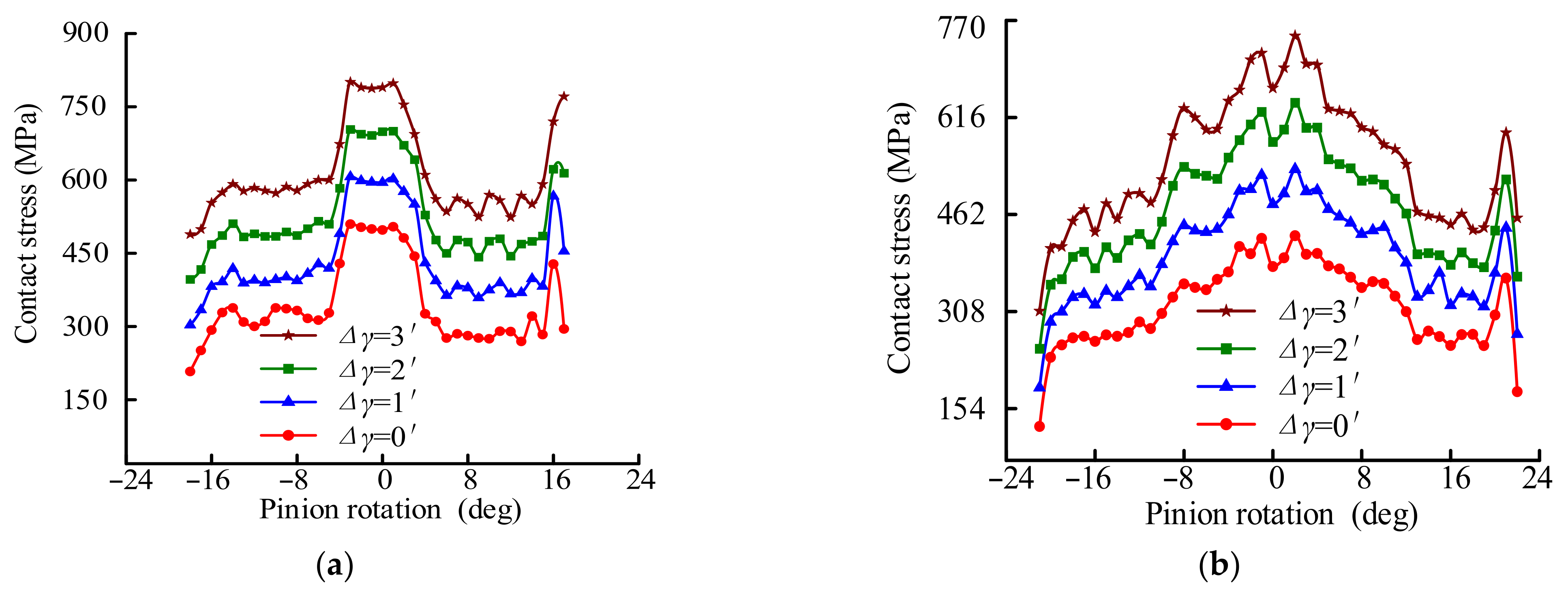
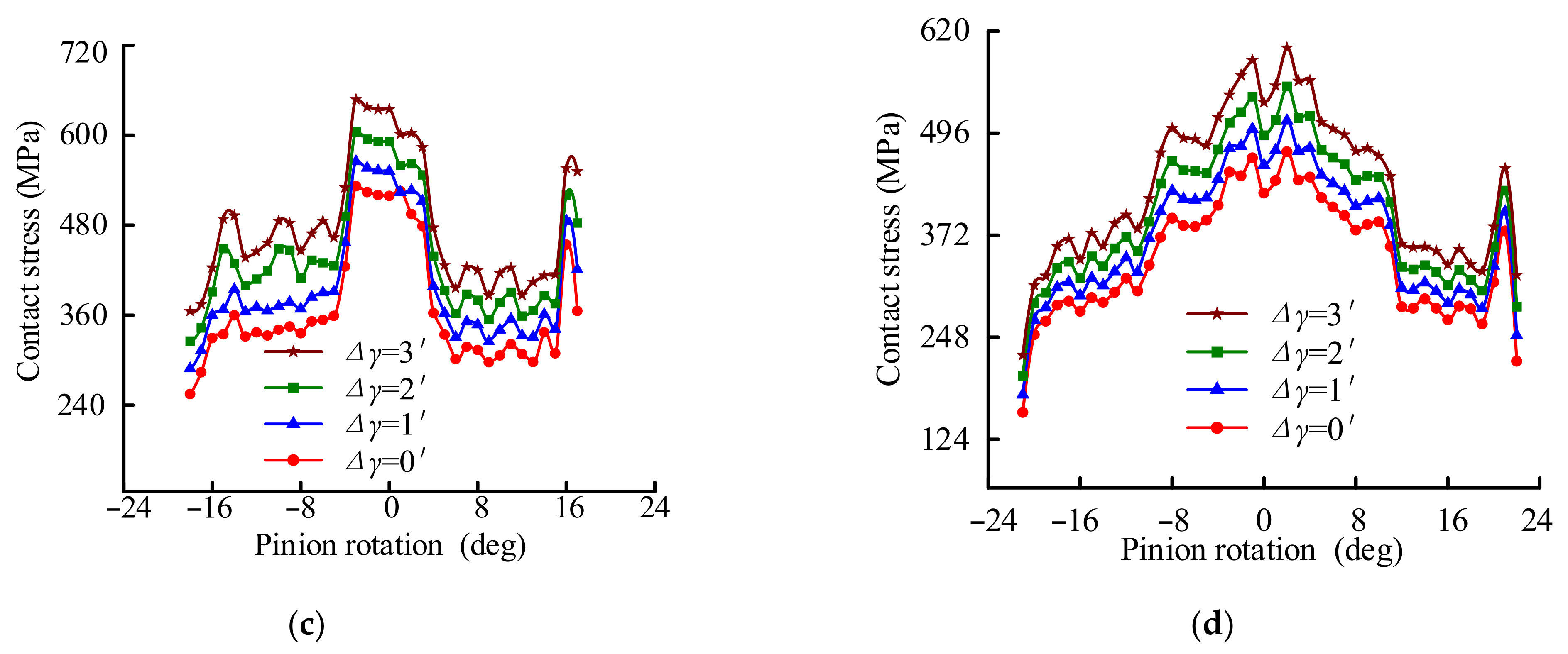
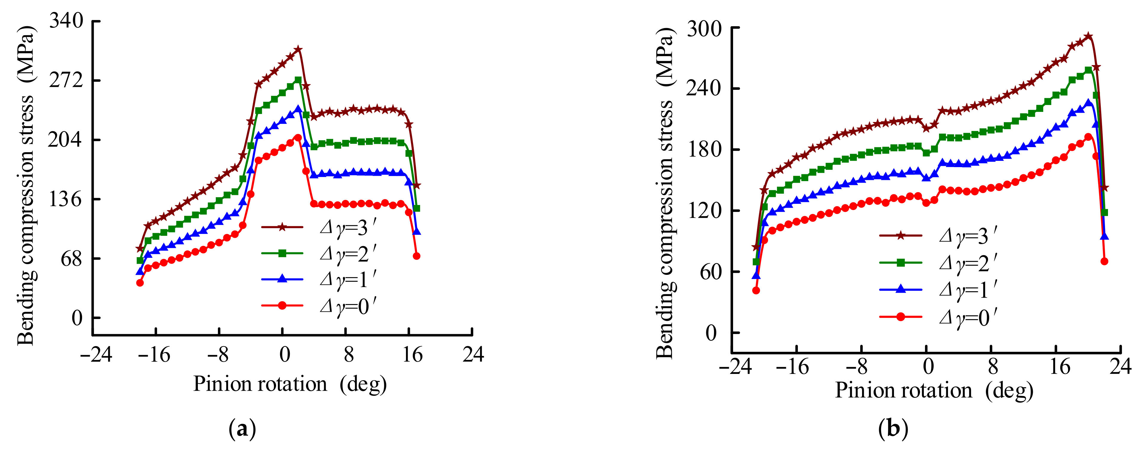
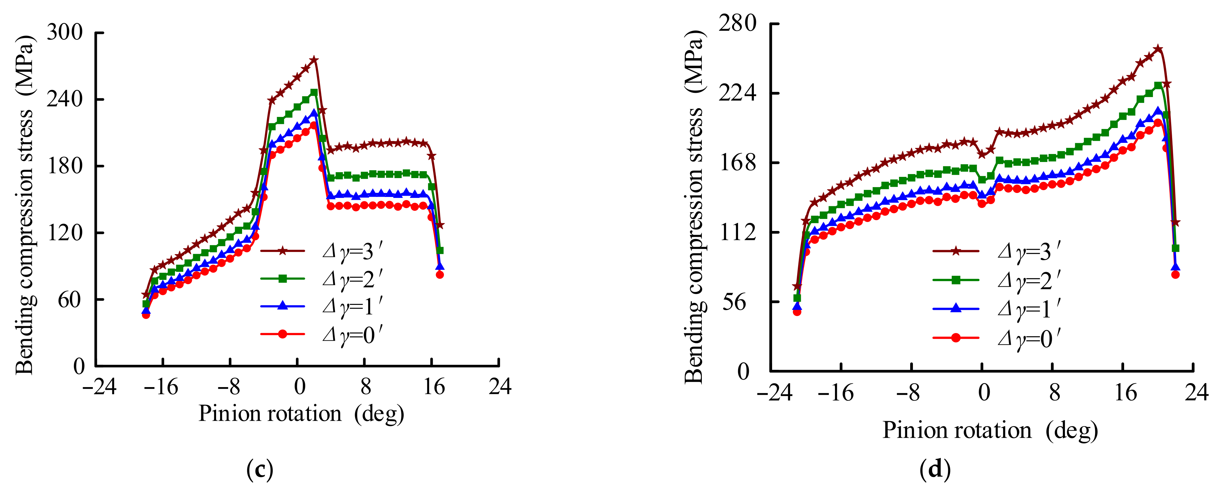
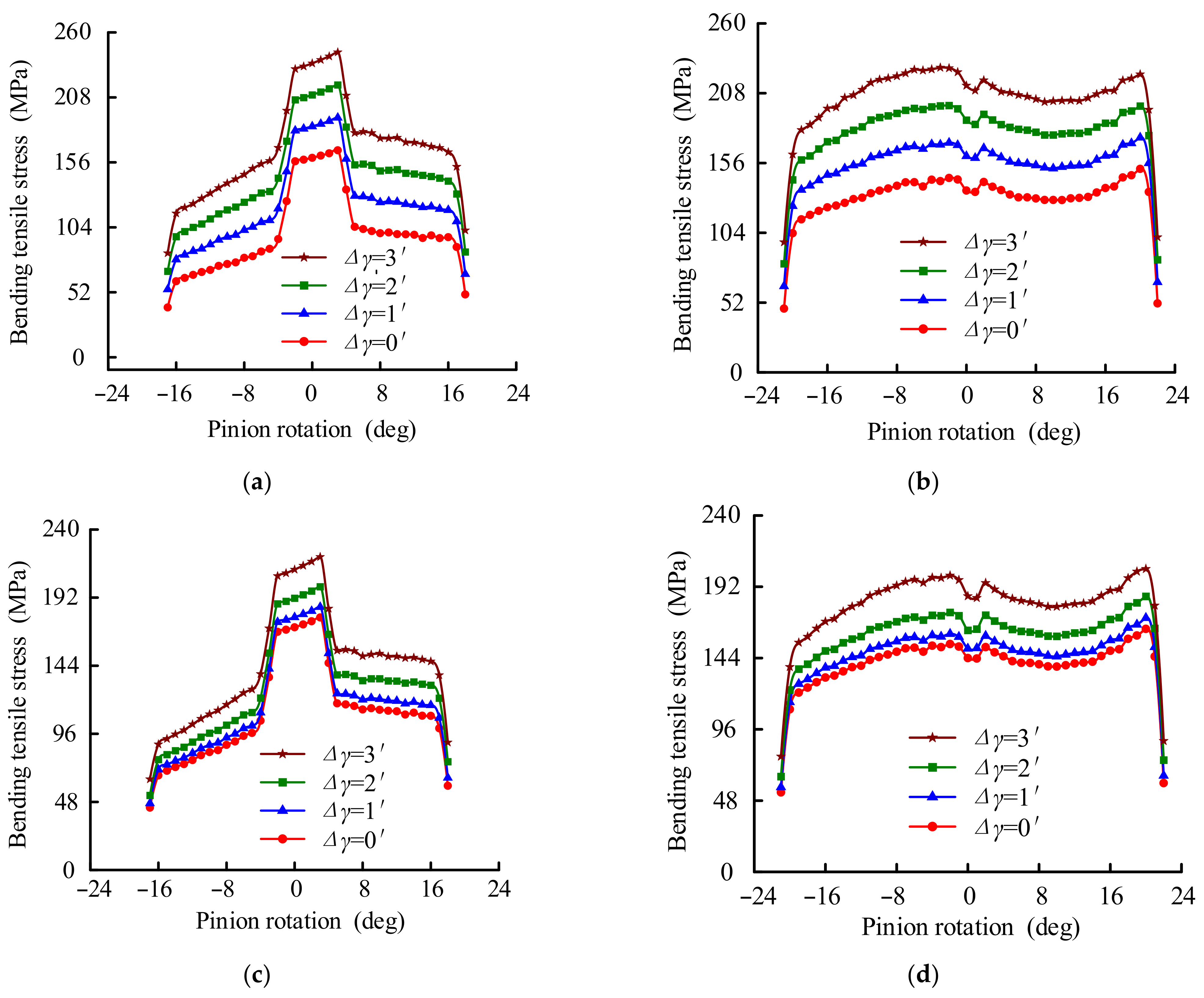
4.2.4. Error-Sensitivity Analysis of the Novel Gears

Errors such as assembly, manufacturing, and so on are unavoidable in actual practice. Therefore, in this section, the error sensitivity of the novel gears is carried out and compared with involute gears.
In this section, the parameters of tooth modification yi (i = 1, 2, and 3) of the novel gears and the involute gears are 8 μm, 8 μm, and 8 mm, respectively.
Figure 17 illustrates the tooth surface load distribution of the novel gears and the involute gears with and without tooth modification at the pitch circle position. It can be seen from Figure 17 that the load of the gears transfers rapidly from one side to the other with the increase in misalignment error, and this is extremely detrimental to the gear transmission. Comparing the conditions before and after tooth modification, it can be seen that the tooth surface load distribution has been significantly improved after tooth modification. Moreover, it can be observed that the tooth surface load distribution of the given novel gears is significantly better than that of the involute gears, whether modified or not. In order to visually observe the effect of the misalignment errors and the tooth modification on tooth surface load distribution, Figure 18 gives the contour map of the von Mises stresses of the involute gears and the novel gears when the misalignment error is equal to 3′. The contact position of both gear pairs is at the pitch point.
In the following, the stresses of the unmodified and modified novel gears with different misalignment errors are calculated and compared with the involute gears with the same modified value. Figure 19 shows the comparison of contact stress between novel gears and involute gears with different misalignment errors. Table 4 gives the maximum contact stress of the unmodified gears. When the misalignment error is 0, the maximum contact stresses of the unmodified involute gears and the novel gears are 510.65 and 428.41 MPa, respectively; when the misalignment error increases to 3′, the maximum contact stress of the unmodified involute gears is 800.69 MPa and the unmodified novel gears is 745.41 MPa. Table 5 shows the maximum contact stress of the modified gears. When the misalignment error is 0, the maximum contact stresses of the modified involute gears and the novel gears are 531.94 and 473.53 MPa, respectively; when the misalignment error increases to 3′, the maximum contact stress of the modified involute gears is 647.75 MPa and the unmodified novel gears is 599.72 MPa. Whether modified or not, the contact stress of the novel gears is less than that of the involute gears.
Figure 20 gives the variations in the bending compressive stress of the presented novel gears with the misalignment error, compared with that of the involute gears. It can be seen from the figures that the misalignment error has a great influence on bending compressive stress; the bending compressive stress of the novel gears and the involute gears gradually increases with the increase in the misalignment error. Moreover, similar to the results for contact stress in Figure 19, the bending compressive stress of the novel gears in much less than that of the involute gears, whether modified or not. For the unmodified gears, the bending compressive stress of the novel gears is 5.62%, 5.38%, and 5.28% less than that of the involute gears at the misalignment errors of 1′, 2′, and 3′, respectively; for the modified gears, the bending compressive stress of the novel gears is 7.91%, 6.51%, and 5.74% less than that of the involute gears at the misalignment errors of 1′, 2′ and 3′, respectively. Figure 21 demonstrates the variations in the bending tensile stress of the presented novel gears and the involute gears with the misalignment errors. Similarly, the bending tensile stress of the given novel gears is less than that of the involute gears. When the misalignment error is equal to 3′, for the unmodified gears, the stress of the novel gears is 6.97% less than the involute one; for the modified gears, the stress of the novel gears is 7.42% less.

5. Conclusions

In this paper, novel non-involute cylindrical gears based on a parabolic path of contact were presented. From the present study, the following conclusions are drawn:
(1)
Compared with the involute gear, the tooth contact stress of the presented novel gear is reduced by 16.10%. The presented novel gear is helpful in reducing tooth surface wear.
(2)
The presented novel gear has higher load capacity than the involute gear. Whether it is modified or not, with or without misalignment error, the calculated stress of the presented novel gear is lower than that of the involute gear.
(3)
Tooth modification has a great influence on the performance of the novel gear. When the misalignment error is 3′, after tooth modification, the contact stress, bending compressive stress, and bending tensile stress of the novel gear are reduced by 19.54%, 10.85%, and 10.14%, respectively.
(4)
Change in the design parameters leads to a change in the tooth profile of the presented novel gears and the change of the dedicated rack-cutters. Considering the processing problem, the cost of the presented novel gear will be higher than for an involute gear.
(5)
Small-batch production of the presented novel gears can be realized based on the dedicated rack-cutter. The presented novel gears processed by the same type of dedicated rack-cutter can be interchanged.
(6)
The presented novel gear in this paper is not mature in some respects, but it has great advantages over the involute gear in others, especially high contact strength. The presented gear has potential application prospects in high-power roadheaders and tunnelling machines.

Author Contributions

Project administration, conceptualization, methodology, and writing—review, C.J.; data curation and software, Q.H.; validation and writing—original draft, J.X.; methodology, writing—review, and editing, H.D. All authors have read and agreed to the published version of the manuscript.

Funding

The authors gratefully acknowledge support from the National Natural Science Foundation of China (Nos. 52005107 and 62173093) and the National Science Foundation of Fujian Province (No. 2020J05100).

Institutional Review Board Statement

Not applicable.

Informed Consent Statement

Not applicable.

Data Availability Statement

The data presented in this study are available from the corresponding authors on request.

Conflicts of Interest

The authors declare no conflict of interest.

Nomenclature

utparameter of the predesigned line of contact path
rithe pitch circle radius of the pinion and gear (i = 1, 2)
ϕ i rotation angle of pinion and gear (i = 1, 2)
m12gear transmission ratio
Nitooth number of pinion and gear (i = 1, 2)
r i , n i position vector and unit normal vector of surface (i = 1, 2)
Sicoordinate system i (i = 1, 2, f, p, g)
[L]i,jcoordinate transmission matrix (from Sj to Si)
v r i sliding velocity of contact point on tooth profile of pinion and gear
k1, k2parabolic coefficients
y1, y2, y3parameters of tooth longitudinal modification
δFmodified value of the grid node
Δγmisalignment error
σcmaximum contact stress
σbcmaximum bending compressive stress
σbtmaximum bending tensile stress

References

  1. Yeh, T.; Yang, D.C.H.; Tong, S.H. Design of new tooth profiles for high-load capacity gears. Mech. Mach. Theory 2001, 36, 1105–1120. [Google Scholar] [CrossRef]
  2. Sun, Q.; Sun, Y.H. The generation principle, mathematical models of variable involute, and its application. Proc. Inst. Mech. Eng. Part C J. Mech. Eng. Sci. 2018, 232, 828–841. [Google Scholar] [CrossRef]
  3. Hsieh, C.F.; Fuentes-Aznar, A. Performance prediction method of cycloidal speed reducers. J. Braz. Soc. Mech. Sci. 2019, 41, 186. [Google Scholar] [CrossRef]
  4. Chen, Z.; Zeng, M.; Fuentes-Aznar, A. Computerized design, simulation of meshing and stress analysis of pure rolling cylindrical helical gear drives with variable helix angle. Mech. Mach. Theory 2020, 153, 103962. [Google Scholar] [CrossRef]
  5. Hussein, A.W.; Abdullah, M.Q. A novel design for enhancing the surface durability of the spur gear systems. Proc. Inst. Mech. Eng. Part C J. Mech. Eng. Sci. 2022, 236, 10143–10160. [Google Scholar] [CrossRef]
  6. Liu, C.Z.; Qin, D.T.; Liao, Y.H. Dynamic model of variable speed process for herringbone gears including friction calculated by variable friction coefficient. J. Mech. Des. 2014, 136, 041006. [Google Scholar] [CrossRef]
  7. Chapron, M.; Velex, P.; Bruyère, J.; Becquerelle, S. Optimization of profile modifications with regard to dynamic tooth loads in single and double-helical planetary gears with flexible ring-gears. J. Mech. Des. 2016, 138, 023301. [Google Scholar] [CrossRef]
  8. Marimuthu, P.; Muthuveerappan, G. Investigation of load carrying capacity of asymmetric high contact ratio spur gear based on load sharing using direct gear design approach. Mech. Mach. Theory 2016, 96, 52–74. [Google Scholar] [CrossRef]
  9. Sekar, R.P. Determination of load dependent gear loss factor on asymmetric spur gear. Mech. Mach. Theory 2019, 135, 322–335. [Google Scholar] [CrossRef]
  10. Wang, J.; Luo, S.M.; Su, D.Y.; Chang, X.F. Geometric design and simulation of tooth profile using elliptical segments as its line of action. J. Cent. South Univ. 2015, 22, 2119–2126. [Google Scholar] [CrossRef]
  11. Lu, F.X.; Cao, X.C.; Liu, W.P. Optimal design of high efficiency double helical gear based on dynamics model. SN Appl. Sci. 2021, 3, 13. [Google Scholar] [CrossRef]
  12. Litvin, F.L.; Lu, J. Computerized design and generation of double circular-arc helical gears with low transmission errors. Comput. Method Appl. Mech. Eng. 1995, 127, 57–86. [Google Scholar] [CrossRef]
  13. Zhang, H.; Hua, L.; Han, X.H. Computerized design and simulation of meshing of modified double circular-arc helical gears by tooth end relief with helix. Mech. Mach. Theory 2010, 45, 46–64. [Google Scholar] [CrossRef]
  14. Yao, L.G.; Gu, B.; Huang, S.J.; Wei, G. Mathematical modeling and simulation of the external and internal double circular-arc spiral bevel gears for the nutation drive. J. Mech. Des. 2010, 132, 021008. [Google Scholar] [CrossRef]
  15. Wen, L.; Chen, Z.; Fuentes, A. Computerized design, simulation of meshing and stress analysis of non-generated double circular-arc helical gear drives with different combinations of transverse pressure angle. Mech. Mach. Theory 2022, 170, 104683. [Google Scholar] [CrossRef]
  16. Song, C.S.; Li, X.Z.; Yang, Y.; Sun, J. Parameter design of double-circular-arc tooth profile and its influence on meshing characteristics of harmonic drive. Mech. Mach. Theory 2022, 167, 104567. [Google Scholar] [CrossRef]
  17. Su, Y.J.; Yao, L.G.; Zhang, J. Contact dynamics analysis of nutation drive with double circular-arc spiral bevel gear based on mathematical modeling and numerical simulation. Mech. Sci. 2021, 12, 185–192. [Google Scholar] [CrossRef]
  18. Jiang, B.; Ren, Z.; Duan, J. Research of the load distribution at the meshing point of double circular arc gear. J. Mech. Transm. 2017, 41, 58–61. [Google Scholar]
  19. Lu, J.; Litvin, F.L.; Chen, J.S. Load share and finite-element stress-analysis for double circular-arc helical gears. Math. Comput. Model. 1995, 21, 13–30. [Google Scholar] [CrossRef]
  20. Qu, W.T.; Peng, X.Q.; Zhao, N.; Guo, H. Finite element generalized tooth contact analysis of double circular arc helical gears. Struct. Eng. Mech. 2012, 43, 439–448. [Google Scholar] [CrossRef]
  21. Liu, X.; Wu, F.; Wang, L. Research of quasi transverse double circular-arc gear sensitivity in centre distance error. J. Mech. Transm. 2012, 36, 28–31. [Google Scholar]
  22. Luo, S.M.; Wu, Y.; Wang, J. The generation principle and mathematical models of a novel cosine gear drive. Mech. Mach. Theory 2008, 43, 1543–1556. [Google Scholar] [CrossRef]
  23. Koide, T.; Yukawa, T.; Takami, S.; Ueda, A.; Moriwaki, I.; Tamura, A.; Hongu, J. Tooth surface temperature and power transmission efficiency of plastic sine-curve gear. J. Adv. Mech. Des. Syst. 2017, 11, 6. [Google Scholar]
  24. Wang, J.; Hou, L.; Luo, S.M.; Wu, R.Y. Active design of tooth profiles using parabolic curve as the line of action. Mech. Mach. Theory 2013, 67, 47–63. [Google Scholar] [CrossRef]
  25. Liang, D.; Chen, B.K.; Gao, Y.N. The generation principle and mathematical model of a new involute-helix gear drive. Proc. Inst. Mech. Eng. Part C J. Mech. Eng. Sci. 2013, 227, 2834–2843. [Google Scholar] [CrossRef]
  26. Wang, Y.Z.; Ren, S.Y.; Li, Y. Design and manufacturing of a novel high contact ratio internal gear with a circular arc contact path. Int. J. Mech. Sci. 2019, 153–154, 143–153. [Google Scholar] [CrossRef]
  27. Peng, S.; Chen, B.K.; Liang, D.; Zhang, L.H.; Qin, S.L. Mathematical model and tooth contact analysis of an internal helical gear pair with selectable contact path. Int. J. Precis. Eng. Manuf. 2018, 19, 837–848. [Google Scholar] [CrossRef]
  28. Liu, L.; Meng, F.; Ni, J.L. A novel non-involute gear designed based on control of relative curvature. Mech. Mach. Theory 2019, 140, 144–158. [Google Scholar] [CrossRef]
  29. Chen, Z.; Ding, H.F.; Zeng, M. Nonrelative sliding gear mechanism based on function-oriented design of meshing line functions for parallel axes transmission. Adv. Mech. Eng. 2018, 10, 13. [Google Scholar] [CrossRef]
  30. Wang, J.; Luo, S.M.; Wu, Y. A method for the preliminary geometric design of gear tooth profiles with small sliding coefficients. J. Mech. Des. 2010, 132, 8. [Google Scholar] [CrossRef]
  31. Trobentar, B.; Kulovec, S.; Hlebanja, G.; Glodež, S. Experimental failure analysis of S-polymer gears. Eng. Fail. Anal. 2020, 111, 104496. [Google Scholar] [CrossRef]
  32. Zorko, D. Investigation on the high-cycle tooth bending fatigue and thermo-mechanical behavior of polymer gears with a progressive curved path of contact. Int. J. Fatigue 2021, 151, 106394. [Google Scholar] [CrossRef]
  33. Zorko, D.; Duhovnik, J.; Tavčar, J. Tooth bending strength of gears with a progressive curved path of contact. J. Comput. Des. Eng. 2021, 8, 1037–1058. [Google Scholar] [CrossRef]
  34. Sun, Q.; Sun, Y.H.; Chen, C. Computation of meshing imprint and loading capacity of S-shaped gear pair with small number (2–6) of pinion teeth. J. Braz. Soc. Mech. Sci. 2021, 43, 415. [Google Scholar] [CrossRef]
  35. Litvin, F.L.; Fuentes, A. Gear Geometry and Applied Theory; Cambridge University Press: Cambridge, UK, 2004. [Google Scholar]
  36. Fong, Z.H.; Chiang, T.W.; Tsay, C.W. Mathematical model for parametric tooth profile of spur gear using line of action. Math. Comput. Model. 2002, 36, 603–614. [Google Scholar]
Figure 1. The novel non-involute gears and involute gears. (a) Novel non-involute gears; (b) Involute gears.
Mathematics 10 04290 g001
Figure 2. Coordinate systems of meshing gears.
Mathematics 10 04290 g002
Figure 3. Derivation of the tooth profile of the rack-cutter based on path of contact.
Mathematics 10 04290 g003
Figure 4. Parabolic path of contact at the first quadrant.
Mathematics 10 04290 g004
Figure 5. Parabolic path of contact at the third quadrant.
Mathematics 10 04290 g005
Figure 6. Designation of tooth modification. (a) Gridding surface of the unmodified tooth; (b) Gridding surface of the modified value.
Mathematics 10 04290 g006
Figure 7. 3D grid model of the modified gears.
Mathematics 10 04290 g007
Figure 8. Coordinate systems of meshing gears with misalignment error Δγ.
Mathematics 10 04290 g008
Figure 9. Designation of the parabolic path of contact of the novel gears.
Mathematics 10 04290 g009
Figure 10. Effect of parabolic coefficient k1 on the tooth profile of the novel gears. (a) Tooth profile of the pinion; (b) Tooth profile of the gear.
Mathematics 10 04290 g010
Figure 11. Effect of parabolic coefficient k2 on the tooth profile of the novel gears. (a) Tooth profile of the pinion; (b) Tooth profile of the gear.
Mathematics 10 04290 g011
Figure 12. The tooth profile of the rack-cutters of the novel pinion and gear, k1 = k2 = 0.32.
Mathematics 10 04290 g012
Figure 13. Comparison of bearing capacity between novel gears and involute gears. (a) Contact stress; (b) Bending compressive stress; (c) Bending tensile stress.
Mathematics 10 04290 g013
Figure 14. Tooth surface load distribution of the novel gears at the pitch circle position. (a) Parameter of tooth modification y3 = 0; (b) Parameter of tooth modification y3 = 8 mm.
Mathematics 10 04290 g014
Figure 15. Comparison of tooth surface load distribution at the pitch circle position. (a) Unmodified; (b) Modified values y1 = y2 = 8 μm and y3 = 0; (c) Modified values y1 = y2 = 8 μm and y3 = 8 mm.
Mathematics 10 04290 g015
Figure 16. Comparison of stress of novel gears with different values of tooth modification. (a) Contact stress, y3 = 0; (b) Contact stress, y3 = 8 mm; (c) Bending compressive stress, y3 = 0; (d) Bending compressive stress, y3 = 8 mm; (e) Bending tensile stress, y3 = 0; (f) Bending tensile stress, y3 = 8 mm.
Mathematics 10 04290 g016aMathematics 10 04290 g016b
Figure 17. Comparison of tooth surface load distribution between novel gears and involute gears with different misalignment errors. (a) Unmodified involute gears; (b) Unmodified novel gears; (c) Modified involute gears; (d) Modified novel gears.
Mathematics 10 04290 g017
Figure 18. Comparison of tooth surface load distribution between novel gears and involute gears at the pitch circle position, Δγ = 3′. (a) Unmodified involute gear; (b) Unmodified novel gear; (c) Modified involute gear; (d) Modified novel gear.
Mathematics 10 04290 g018aMathematics 10 04290 g018b
Figure 19. Comparison of contact stress between novel gears and involute gears with different misalignment errors. (a) Unmodified involute gears; (b) Unmodified novel gears; (c) Modified involute gears; (d) Modified novel gears.
Mathematics 10 04290 g019aMathematics 10 04290 g019b
Figure 20. Comparison of bending compressive stress between novel gears and involute gears with different misalignment errors. (a) Unmodified involute gears; (b) Unmodified novel gears; (c) Modified involute gears; (d) Modified novel gears.
Mathematics 10 04290 g020aMathematics 10 04290 g020b
Figure 21. Comparison of bending tensile stress between novel gears and involute gears with different misalignment errors. (a) Unmodified involute gears; (b) Unmodified novel gears; (c) Modified involute gears; (d) Modified novel gears.
Mathematics 10 04290 g021
Table 1. Design parameters of gears.
Design ParameterNovel GearsInvolute Gears
Tooth number17/2917/29
Normal module (mm)2.252.25
Face width (mm)2525
Addendum coefficient11
Dedendum coefficient1.251.25
Root radius (mm)11
Contact ratio1.931.58
k10.32/
k20.32/
Table 2. Comparison of maximum stress between novel gears and involute gears (MPa).
GearsContact Stress
σc
Bending Compressive
Stress σbc
Bending Tensile
Stress σbt
Involute gears510.65206.39165.65
Novel gears
Decrease
428.41
16.10%
192.45
6.75%
151.59
8.49%
Table 3. Maximum stress of novel gears with different modified values (MPa).
Modified ValueContact Stress
σc
Bending Compressive
Stress σbc
Bending Tensile
Stress σbt
y1/μmy2/μmy3/mm
000428.41192.45151.59
440448.62194.19158.44
880479.87206.09167.54
12120529.60217.86176.55
448438.81191.27156.53
888473.53200.18200.18
12128507.97208.74170.51
Table 4. Comparison of maximum stress between unmodified novel gears and unmodified involute gears with different misalignment errors (MPa).
GearsConditionContact Stress
σc
Bending Compressive stress σbcBending Tensile Stress σbt
Involute
gears
Δγ = 0′510.65206.39165.65
Δγ = 1′606.65238.74191.73
Δγ = 2′703.67272.88217.91
Δγ = 3′800.69307.39244.06
Novel
gears
Δγ = 0′428.41192.45151.59
Δγ = 1′533.78225.32174.97
Δγ = 2′639.50258.18198.84
Δγ = 3′745.41291.15227.04
Table 5. Comparison of maximum stress between modified novel gears and modified involute gears with different misalignment errors (MPa).
GearsConditionContact Stress
σc
Bending Compressive stress σbcBending Tensile Stress σbt
Involute
gears
Δγ = 0′531.94216.60178.04
Δγ = 1′564.92227.21185.37
Δγ = 2′604.31246.41199.69
Δγ = 3′647.75275.36220.69
Novel
gears
Δγ = 0′473.53200.18163.66
Δγ = 1′510.99209.24171.05
Δγ = 2′553.01230.36185.52
Δγ = 3′599.72259.56204.01
Publisher’s Note: MDPI stays neutral with regard to jurisdictional claims in published maps and institutional affiliations.

