1. Introduction
Natural convection in closed and open geometry has been and is still an interesting research subject, due to its omni-presence in natural phenomena and engineering applications such as drying, electronic cooling, crystallization, casting, solar collectors and buildings HVAC.
Several authors investigated the natural convection effect of using discrete heat sources or partial heating on the convective heat transfer in cavities. Al-Rashed et al. [
1] studied the natural convection in a partially heat 3D encloser. Several configurations related to the position of the heater have been studied and the results showed that it is an optimizing parameter for the heat transfer. Kondrashov and Burkova [
2] studied the effect of local heating of the free convection in a thin layer and found that for low Rayleigh number values, the flow field is symmetrical. This symmetry disappears for Ra values higher than the critical Rayleigh number. Yigit et al. [
3] considered a power-law fluid filled square cavity heated partially from blow and symmetrically cooled from the top. The author concluded the main parameter governing the heat transfer to be the Rayleigh number. Cho [
4] studied the heat transfer and entropy generation in a porous partially heated cavity filled with a nanofluid and having a wavy wall. The author mentioned that the increase of nanoparticle concentration and the length of the heated surface, leads to the enhancement of the heat transfer. Koca et al. [
5] studied a triangular cavity partially heated from below. The authors considered several fluids having various Prandtl numbers and found that the flow is significatively affected by changing the fluid. Similar geometry, but filled with a porous media, was considered by Rao and Barman [
6]. The author concluded that the porosity and Rayleigh number are the main parameters that govern the flow. Alam et al. [
7] studied the effect of partial heating and cooling on the free convection in a 2D cavity. It was found that in addition to Rayleigh number, the aspect ratio plays an important role in the heat transfer. Lajnef et al. [
8] studied the effect of capillarity on the MHD flow in a partially heated cavity. They found that the induced Lorentz force opposes the thermo-capillary effects leading to a control of the flow. Rahimi et al. [
9] investigated the irreversibility production in a partially heated nanofluid filled cavity and found that the entropy production can be reduced by choosing the optimal values of Rayleigh number, nanofluid concentration and the arrangement of the partial heating.
On the other hand, the number of studies on the convective heat transfer in open enclosures is increasing. Fontana et al. [
10] considered a differentially heated open 2D cavity equipped with an internal heat source. The results showed that the opening had a very important effect on the heat transfer and flow structure. Oztop et al. [
11] studied a square cavity filled with porous media with partial openings. They concluded that the heat transfer can be optimized by varying the opening position. Kolsi et al. [
12] studied the 3D natural convection in an open side cavity filled with CNT-nanofluid. In this study, the flow is controlled by the existence of an inclined plate and the application of an external magnetic field. It was found that the flow and temperature fields depend on the inclination of the plate and the intensity of the magnetic field. In addition, the heat transfer is enhanced by increasing the CNT volume fraction. Fontana et al. [
13] numerically studied the free convection in a partially opened cube cavity equipped with a heat source at the bottom wall. The authors mentioned that the heat transfer and the fluid structure depend significatively on Prandtl number. Bilgen and Oztop [
14], considered an inclined partially open cavity with differentially heated vertical walls. It concluded that the heat transfer can be optimized for a specific couple of inclination and opening positions. Kolsi et al. [
15] studied the effect of a diamond shaped internal obstacle on the 3D natural convection in an open sided cavity. The results show that the presence of the obstacle controls the flow and the heat transfer in the cavity. Al-Rashed et al. [
16] studied the free convection in a nanofluid filled parallelogrammic 3D cavity heated from the bottom by a discrete heat source and opened from the top. The increases of the size of the heat source and of the nanoparticle’s concentration were found to significatively enhance the heat transfer. Chen et al. [
17] performed a numerical study using LBM method on the free convection in a 2D open cavity filled partially with a porous media. They proved that the LBM is a performant technique that can be used in such complex configurations. Oztop et al. [
18] studied the 3D natural convection and entropy generation in partially open cavities using the FVM. The results revealed that the heat transfer and irreversibility production to be higher for larger openings. Lauriat and Desrayaud [
19] studied the coupled convective and radiative heat transfer in partially opened cavities. The authors mentioned that the radiation is more dominant compared to convection for all the cases. Gangawane et al. [
20] studied the natural convection in partially heated open ended square cavities using the LBM. The authors studied various fluids and concluded that higher heat transfer occurs in the case of water. In addition, they proposed new correlations allowing the evaluation of the Nusselt number. Bondareva et al. [
21] studied the entropy production during the buoyancy convection in a triangular cavity filled with a nanofluid equipped with an opening. The main conclusion was that the addition of nanoparticles leads to the enhancement of the heat transfer and the reduction of the flow intensity. Gangawane [
22] studied the MHD convective heat transfer in partially heated open cavity. The author mentioned that the lowest heat transfer is encountered for an inclination of the magnetic field equal to 45° and the size of the heater becomes non-effective for Rayleigh values higher than 105. Saleh et al. [
23] investigated the fluid structure interaction during natural convection in an open cavity equipped with two flexible fins. They concluded that the opening size and the oscillation direction can be used as an optimizing parameter for the heat transfer rate. Al-Rashed et al. [
24] considered a double open 3D cavity filled with nanofluid and with an incorporated obstacle. The conclusions indicate that the produced entropy generation depends mainly on the nanoparticles volume fraction and Richardson number. Astanina et al. [
25] used the FEM to study the effect of an external magnetic field on the heat transfer and entropy production in a trapezoidal open cavity partially filled with a porous media. The induced flow was perioding with higher amplitude for higher magnitude of the external magnetic field. Miroshnichenko et al. [
26] studied the same geometry but with a cavity filled with a nanofluid and showed that the magnetic field reduces the heat transfer and the addition of the nanoparticles enhances it.
Some studies were dedicated to different aspects related to natural convection in buildings. Wurtz et al. [
27] used the zonal model approach to study the natural convection in building rooms. The authors concluded that this method is relatively faster compared to CFD methods. Wang et al. [
28] studied the coupled effects of radiation and natural convection in a room having a porous envelope. It was proven that the Nusselt number increase with Rayleigh number was significatively affected by the presence of the radiation. Zhan et al. [
29] considered a building equipped with a single heat source and concluded that for high aspect ratios, the heat source size becomes ineffective. Ben-Nakhi and Mahmoud [
30,
31] used the FVM to numerically study the turbulent buoyancy convection in a roof during winter [
30] and summer [
31]. The authors concluded that Ra and the aspect ratio have an important effect on the flow structure, temperature field and heat transfer rate. Wang et al. [
32] considered the combined effects of natural convective ventilation and radiation in an industrial building. It was found that the heat transfer and ventilation rates increase by increasing Rayleigh number and the surface emissivity. Ziskind et al. [
33] studied the natural ventilation caused by a heat source mounted at the top wall of a story building. The authors mentioned that using such configuration can provide good ventilation of the building. Mokhtarzadeh-Dehghan [
34,
35] studied the 3D natural convection between two floors of a building. The author mentioned that their numerical results are in good concordance with previous experimental findings.
Based on the above-described literature review, most of studies dealing with naturally ventilated cavities having discrete heating are performed for 2D geometries, with the limitation of incorporating a finite internal obstacle. Thus, the novelty of this paper is to study the 3D natural ventilation and entropy generation in a typical room, with an incorporated conductive object using the finite volume method. The flow is caused by a discrete heat source and six geometrical configurations related to its position are studied.
2. Governing Equations and Numerical Procedure
Figure 1 presents the studied configurations. A 3D room heated by a discrete heat source, having two openings at the bottom of the left wall and the top of the right wall, and equipped by an internal obstacle. The considered cases are related to the position of the hot surface. Neglecting the radiative heat transfer, the dimensional equations governing the 3D natural convection are the equations of continuity, momentum and energy, and are presented as follow [
18]:
With the aim to eliminate the gradient pressure terms, which are very difficult to treat and a source of divergences, we used the vector potential-vorticity formulation in its 3D form.
To obtain the dimensionless set of equations, , , , , are used for the, time , velocity , vector potential and vorticity , respectively. The dimensionless temperature is .
And the dimensionless equations become:
with,
and Ra =
.
Equation (6) is to be solved in the solid portion (Wood) with
ks as conductivity. The heat flux continuity at the solid–fluid interface is expressed as:
The total dimensionless entropy generation is expressed as:
Using the expression of dissipation function:
The total dimensional entropy generation becomes [
18]:
The dimensionless local entropy generation is [
18]:
with
.
The total entropy generation and Bejan number are expressed as:
and
The local Nusselt number at the hot surface is expressed as:
with
n is the normal vector to the hot surface.
The average Nusselt number on hot wall is:
with
and
are the tangent vectors to the hot surface.
The dimensionless boundary conditions are:
Temperature
on all the walls.
if and if at open boundaries
Vorticity
, , at and 1
, , at and 1
, , at and 1
Potential vector
at and 1
at and 1
at and 1
Velocity
on all walls
at open boundaries.
The scalar equations are expressed as:
The generalized equation is expressed as:
with:
Based on the pure implicit scheme algebraic equations become:
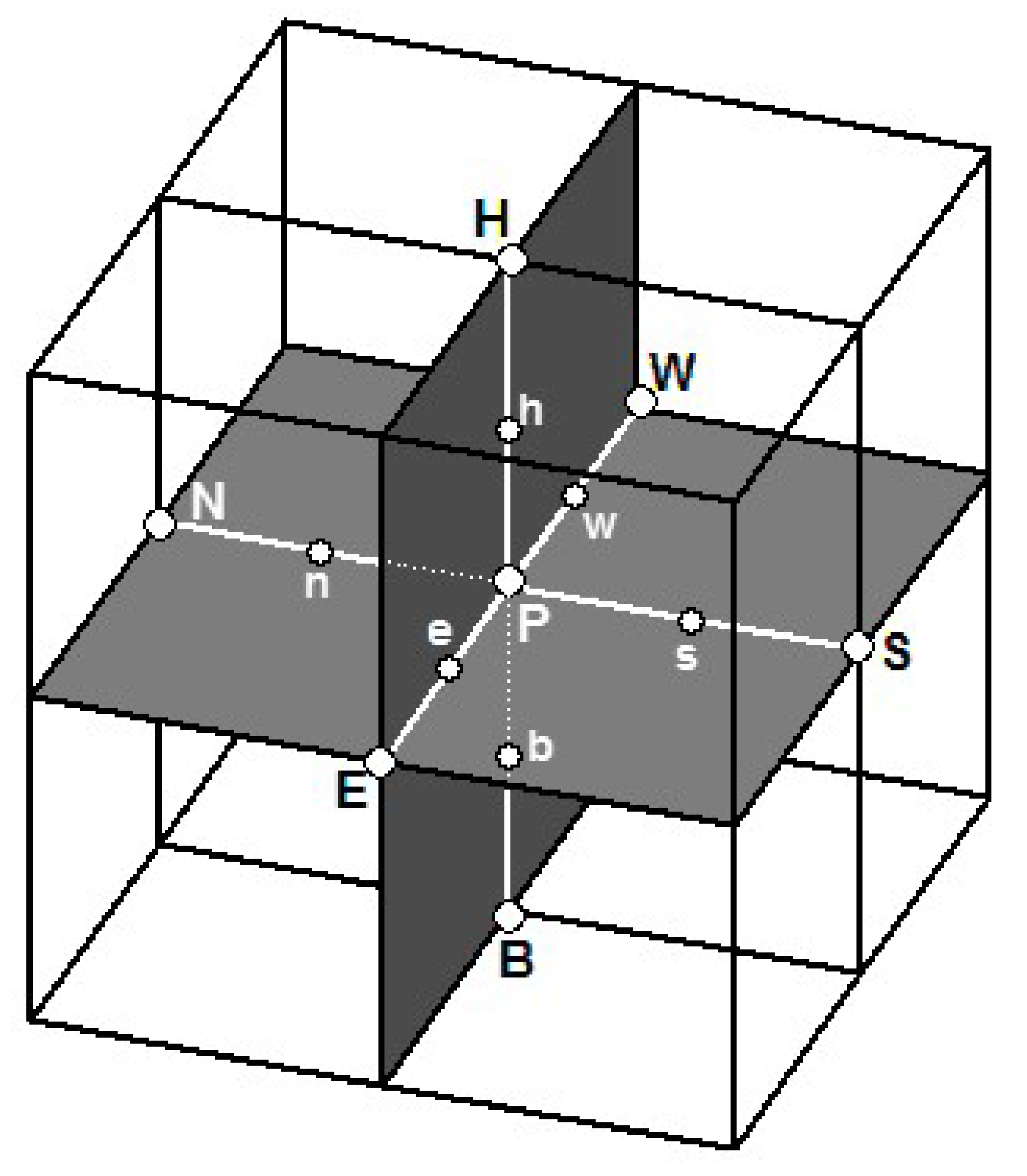
A single control volume is shown in
Figure 2. The total number of nodes in
x,
y and
z directions are denoted by,
Nx,
Ny and
Nz, respectively, and the spatial steps are expressed as:
The integration of Equation (21) on the control volume gives:
The superscript “ ° ” indicates the previous time step (explicit scheme).
The source term
is linearized as:
The dimensionless continuity equation is:
By integrating the control volume, we get:
By multiplying the discretized continuity equation by
and by subtracting it from the general equation we obtain:
The discretized equation becomes:
with:
Similarly, the remaining equations are expressed as follow:
Vorticity equation; x-component:
with:
Vorticity equation; y-component:
with:
Vorticity equation; z-component:
with:
Vector potential equations:
The finite volume method based on regular grid is used to discretize the governing equation [
36]. The convective terms are treated via the central-difference scheme and the temporal derivative via the fully implicit method. To accelerate the convergence of the simulations, the successive relaxation iterating scheme is used. It is notable that the advantages of the FVM are that it enforces the conservation of quantities at the discretized level, thus momentum and energy equations remain conserved at a local scale. In addition, fluxes between adjacent control volumes are directly balanced. The Fortran Language is used to write the numerical code with a convergence criterion for each variable expressed as follow:
3. Code Verification and Validation
The model verification is performed by comparing with the quantitative findings of (Wakashima and Saitoh [
37]) for the 3D differentially heated cavity filled with air (
Table 1). In addition, a qualitative verification is performed by comparing the flow structure and the temperature field (
Figure 3) with the results of Bilgen and Oztop [
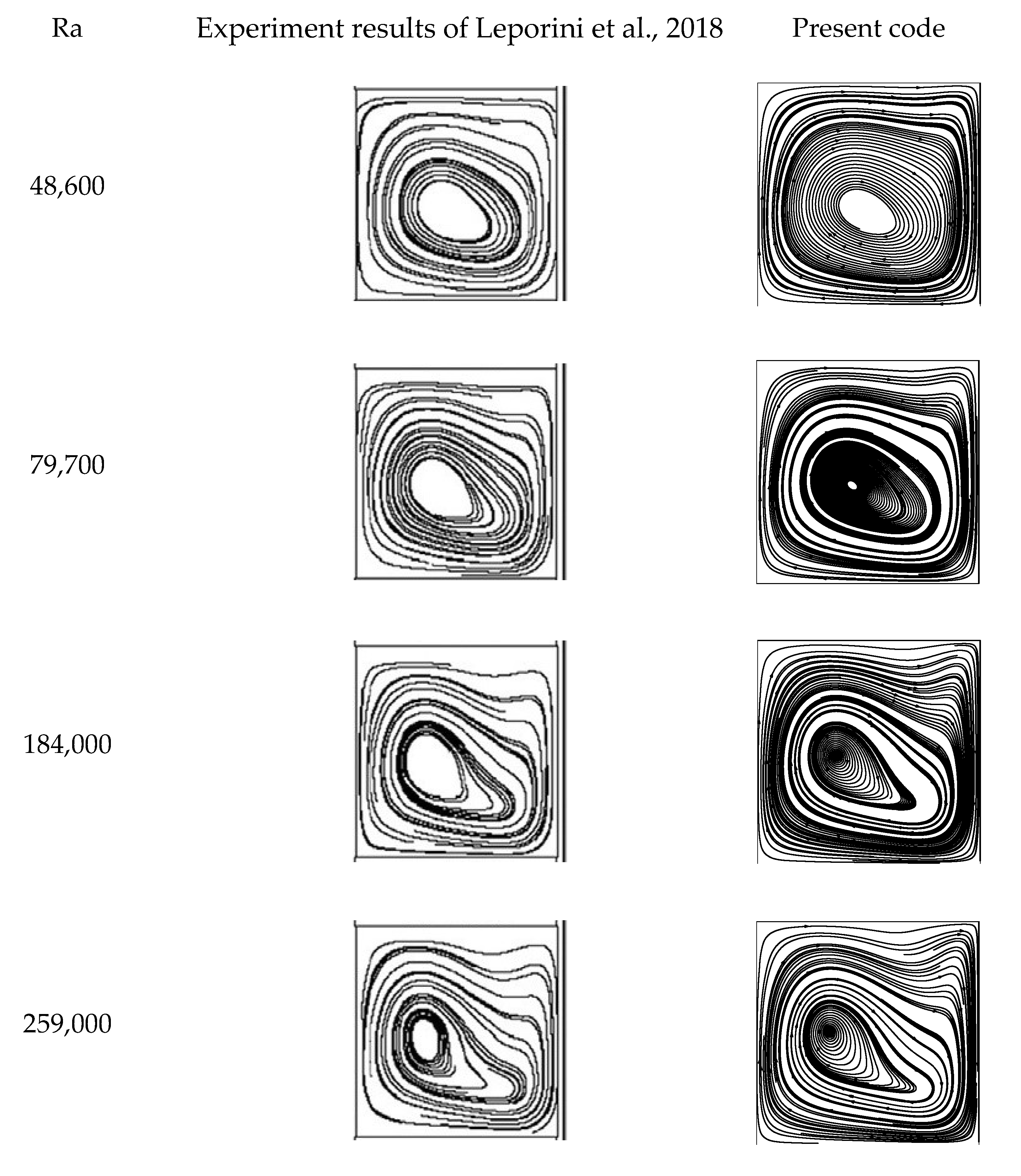
14] in a partially open cavity. In addition to the numerical verification, a validation is performed by comparing the findings of the present code with the results of the experimental study of Leporini et al. [
38] (
Figure 4). A good agreement with the previous results presented in the literature is noticed.
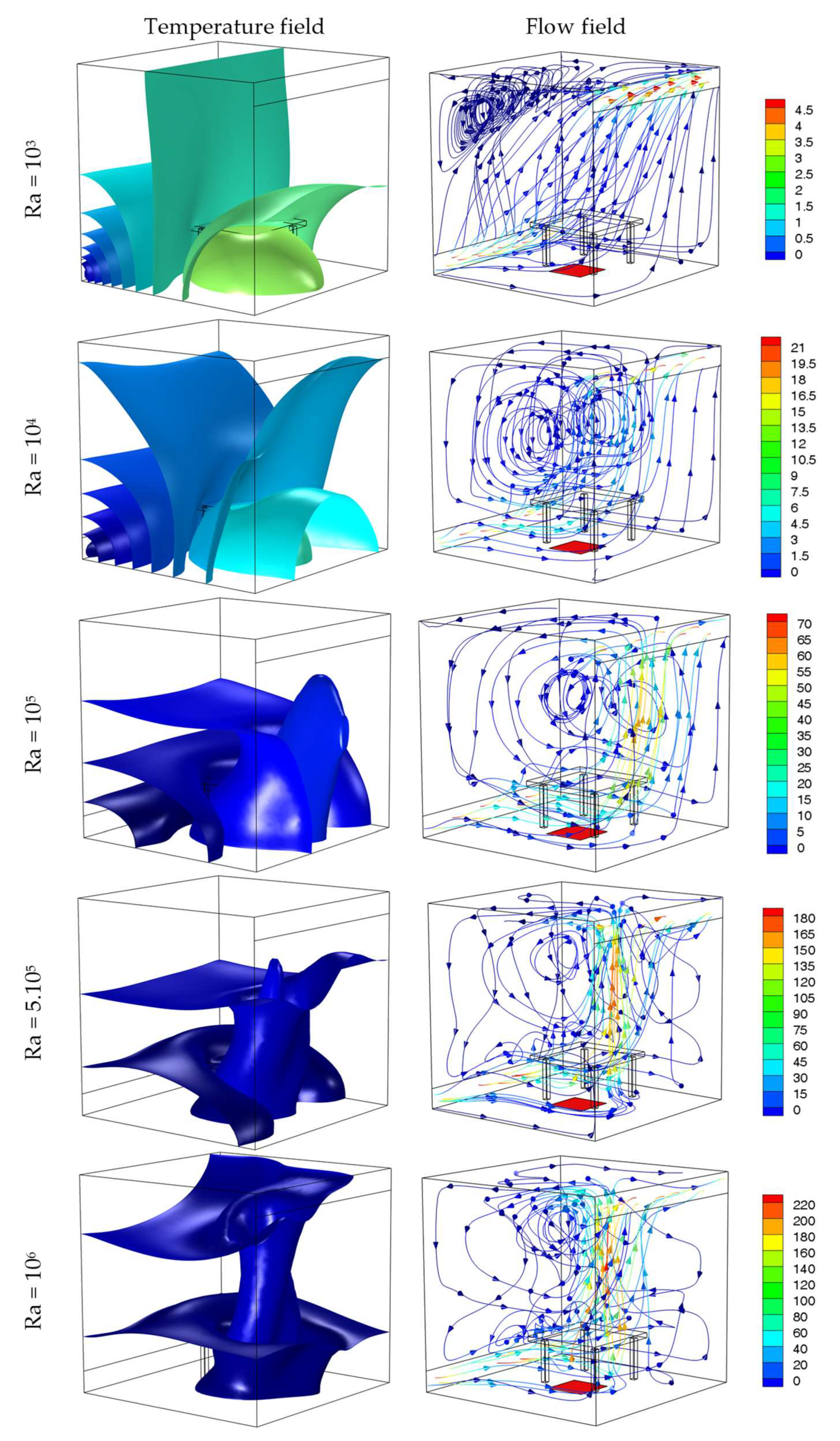
Figure 5 presents the distribution of the temperature iso-surfaces as well as the trajectory of the particles for different Rayleigh numbers. In the case when the heat source centered at the bottom of the plane (x = 1, case 1) is considered for Ra = 10
3, a significant thermal diffusion towards the middle of the chamber was noted. A horizontal and orthogonal thermal stratification at the heat source takes place. The ventilation velocity (at the suction and extraction) is relatively low and the birth of a small eccentric cell at the top near the x = 0 plane is observed. By increasing Ra to 10
4 the horizontal warm air layer, propagation decreases, the ventilation at the exhaust and suction windows accelerate, the size of the cell becomes larger and occupies the entire middle of the enclosure.
It should also be mentioned that the presence of the table as an obstacle does not seem to disturb the flow for low Rayleigh numbers.
For Ra = 105, a strong upward flow of warm air occurs just above the source. The isothermal surfaces show a strong temperature gradient located above the source. This gradient helps the thermal buoyancy forces to dominate the viscous ones, which explains the observed ascending air movement.
When a large value of Rayleigh number is reached (5 × 10⁵ or 106), the table interferes with the flow and a strong vortex activity is noted on the whole left edge of the table. It is also noted that the thermal buoyancy forces generate a strong movement just overhead of the heat source preventing the warm air layers to be blown into the center of the chamber. In this configuration and regardless the Rayleigh number, the main ventilation flow is along the floor (y = 0) and then up the wall equipped with the heat source (x = 1).
Finally, it is important to point out that there is a transition from a horizontal stratification starting from the heat source at Ra = 103 to a vertical stratification starting from the roof for Ra = 106.
For the second case (
Figure 6), where the heat source is moved to the wall containing the suction window (x = 0, case 2), the behavior of the flow has completely changed. Indeed, we note that the main ventilation flow goes up directly to the top of the chamber as soon as it leaves the suction window (x = 0). Then the airflow drifts towards the extraction window, following the ceiling. The flow observed in the first configuration, i.e., the circulation at ground level then climbing up the wall (y = 1) until the suction window still coexists for low Rayleigh number. Moreover, for small Rayleigh numbers, a lateral infiltration of the warm air layer towards the center of the room is achieved while for high Rayleigh numbers, this infiltration is carried out vertically just above the heat source and then a strong thermal gradient is established in this region. In fact, from Ra = 10
5, the thermal buoyancy forces take the control of the ventilation and impose the air circulation in the chamber.
The obstacle effect is only felt for very high Rayleigh numbers. For instance, at Ra = 106, the table imposes a kind of compartmentalization, and a reversed air circulation is observed below and above it.
In
Figure 7, the temperature and particle movement are presented for the case where the heat source is placed on the wall z = 1 (case 3). In this situation, where the heat source is perpendicular and at halfway between the suction and extraction windows, another flow behavior takes place. For low Rayleigh numbers (10
3 and 10
4), it seems that there is a diagonal stratification starting from the heat source towards the suction window. This thermal stratification leads to a penetration of warm air to the core region. Two types of flow occur, the first connecting the suction window to the discharge one through the floor and up along the plane x = 1. The second is created by the thermal buoyancy forces, which drive the air to the top of the room just above the heat source and due to the influence of the roof, there is creation of a rotating cell located in the upper left part of the chamber. By increasing the Rayleigh number, the upward movement on the heat source dominates the flow. This warm air movement eventually impacts the roof and then splits into two parts. One part feeds the discharge source and the other one supplies the rotating thermal vortex. It is also noticed that the vortex center becomes much closer to the roof.
In this condition, we can clearly see the three-dimensional character of the flow with a significant air movement in the z-axis direction. This air movement occurs mainly between the inlet and the heat source. The obstacle effect, especially at the left table border, (border parallel to the inlet window) shows a very intense vortex activity.
Figure 8 presents the distribution of the temperature iso-surfaces as well as the trajectory of the particles for different Rayleigh numbers. In this figure, the heat source is placed on the wall z = 0 (case 4). Unlike all the previous configurations, the air flow from the inlet to the outlet across the floor is almost eliminated. The ventilation occurs mainly in the upper part of the chamber. For Ra = 10
3 the air flow is basically uniform from the bottom of the wall x = 0 (suction) to the top of the wall x = 1 (discharge). A horizontal thermal stratification along the z-axis develops. For Rayleigh numbers higher than 10
4, a chaotic flow seems to take place with air layers rising on one side and falling on the other side and at the same time the development of a three-dimensional movement toward the z-direction. For very high Rayleigh numbers (5 × 10
5 and 10
6) as for the previous configurations, a strong thermal gradient is localized just above the heat source. The buoyancy forces become intense, and a strong air movement is created from the source. The flow is therefore impacting with the roof and then becomes parietal to the extraction window.
The temperature fields and flow structure for the case of bottom heating (case 5) are presented in
Figure 9. The isotherm profile shows a thermal stratification between the heat source and the air inlet opening for low “Ra” values. This stratification becomes isotropic from the heat source for high “Ra” values. The particles trajectory is marked by two dominant flow motions when the Rayleigh number is low: the first starting from the air inlet opening, passing through the ground, and then following the wall x = 1 until it reaches the air outlet opening, and the second immediately towards the top of the chamber from the inlet opening. This second flow hits the room roof causing the creation of a rotational cell with a vortex center located in the upper left corner of the room. A slight increase in Ra up to 10
4 ensures that the rotating cell expands and moves towards the center of the room. For an even higher “Ra”, the main flow movement is essentially horizontal from the inlet to the source and then vertical to the roof from the hot spring. The presence of the table as an obstacle deflects the upward movement to the left side.
If we move the heat source to the ceiling of the room (
Figure 10, case 6), it should be noted that the isothermal layers remain blocked at the roof level; this result is to be expected since the thermal buoyancy forces are ascending forces. The greater the thermal gradient between the heat source and the ambient air (large Ra), the more the convective forces push the hot fluid upwards in the room. At Ra = 10
6 for example it is only the upper quarter of the room that is affected by the heating. Under these conditions the main airflow movement is diagonal from the inlet opening at the bottom of the x = 0 plane to the outlet opening at the top of the x = 1 plane. The presence of secondary movement of low intensity is also detected. This sub movement creates a rotating cell in the upper left corner of the room.
Figure 11 shows the effect of heat source position on thermal, viscous and total entropy generation for Ra = 10
5. As expected, whatever the configuration, the generation of thermal entropy is localized in the immediate vicinity of the heat source, and it is more effective when we get closer to this heat source. Concerning the viscous entropy, regardless of the studied case, the entropy generation is very important at the suction and discharge opening areas due to the ventilation flow. Moreover, in the region just above the heat source the entropy generation is significant as a result of the warm air circulation caused by the natural convention motion.
The variations of average Nusselt number at the heat source for different Ra values and heat source positions are presented in
Figure 12. A similar behavior for all configurations is recorded, with a significant Nusselt number enhancement with the increase of the Rayleigh number. Indeed, by increasing Ra from 10
3 to 10
6 the Nusselt number value is multiplied by 10. However, the case 2 presents a specific variation. Indeed, for Ra < 12,500 the position of the heat source in this second case presents the best thermal exchange with an improvement of about 31.6% compared to the other positions; on the other hand if Ra < 12,500 this second case represents the worst convective heat exchange with an attenuation of 22% for Ra = 10
6. It is also to be mentioned that the heat transfer rate is lowest for case 6 due to the localization of the heat source at the upper wall that limits the heating to the top region.
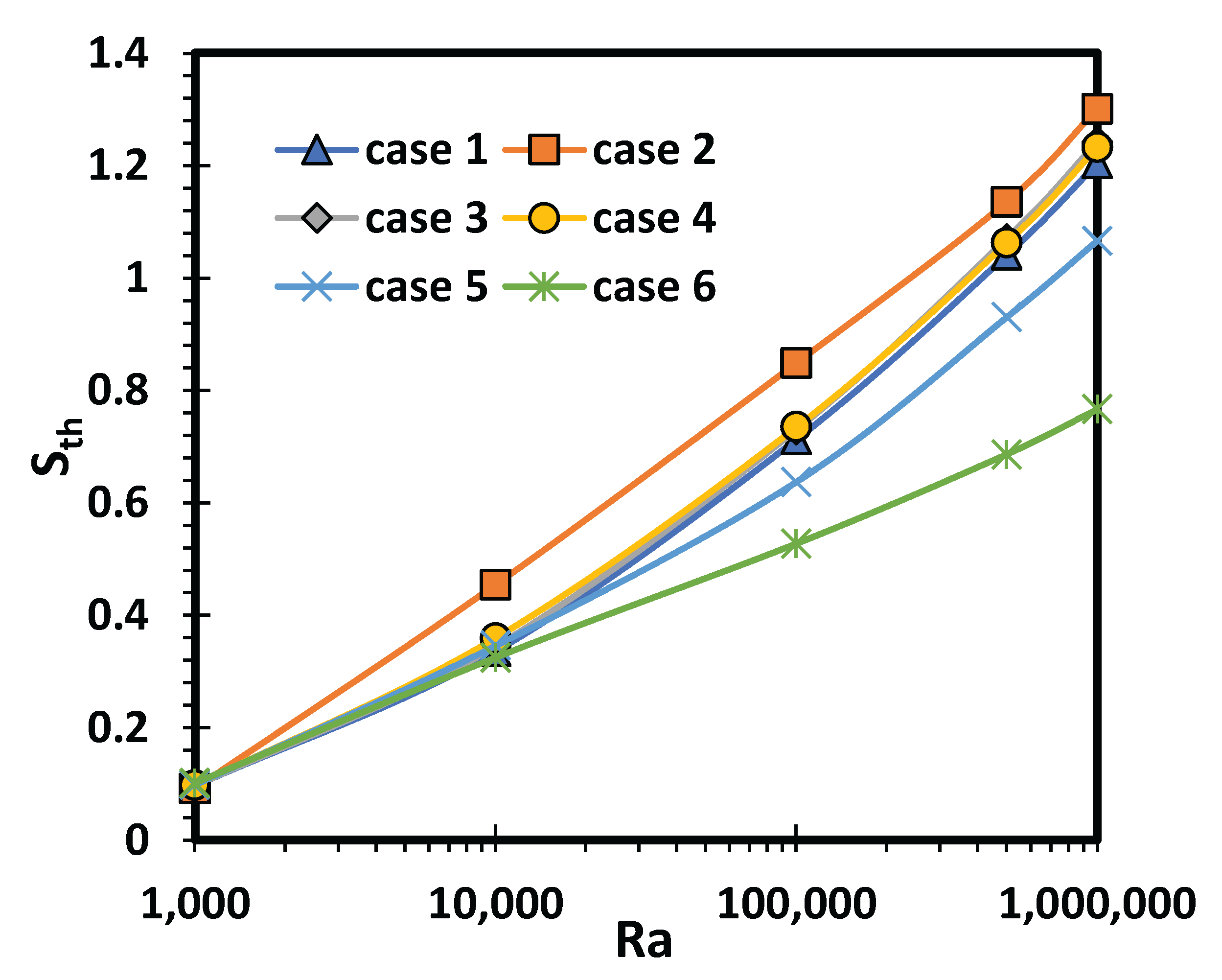
Figure 13 illustrates the thermal entropy generation for various heat source positions and different Ra. As shown in the figure, the average thermal entropy generation increases significantly with the Rayleigh number. In fact, from Ra = 10
3 to 10
6, the generation of average thermal entropy is multiplied by 13. It should be noted that whatever the position of the heat source, the variation of the average thermal entropy is similar except for case 2, where the entropy generation is higher by 33% for Ra = 10
4.
Viscous entropy generation for various heat source positions and different Ra is outlined in
Figure 14. It is clear that the viscous entropy value becomes significative only from a certain critical value of the Rayleigh number around 60,000. Beyond this critical value, an exponential entropy growth is recorded. The heat source configuration for the second case presents again as outstanding compared to the other cases. In fact, in this situation, the generated viscous entropy value is almost double compared to the other configurations.
It is also necessary to mention that the value of the thermal entropy is insignificant compared to the viscous one, which confirms the similar variation between the viscous and total entropy indicated in
Figure 15.
The variation of Be versus of Ra presented in
Figure 16 confirms the previous findings. Indeed, for low Rayleigh numbers, the viscous irreversibility is too weak, which allows for a Bejan number close to 1 and as the Rayleigh number increases, the thermal irreversibility become negligible with respect to the viscous one, thus leading to a Be number close to 0.


