Article

A Linear-Active-Disturbance-Rejection-Based Vertical Takeoff and Acceleration Strategy with Simplified Vehicle Operations for Electric Vertical Takeoff and Landing Vehicles

1
Department of Aerospace Engineering, Nanjing University of Aeronautics and Astronautics, Nanjing 210016, China
2
School of Electronics and Information Engineering, Harbin Institute of Technology, Shenzhen 518055, China
*
Author to whom correspondence should be addressed.
Mathematics 2022, 10(18), 3333; https://doi.org/10.3390/math10183333
Submission received: 8 August 2022 / Revised: 29 August 2022 / Accepted: 1 September 2022 / Published: 14 September 2022
(This article belongs to the Special Issue Applications of Machine Learning in Spacecraft and Aerospace Systems)

Abstract

:
A practical vertical takeoff and acceleration strategy is developed for manned electric vertical takeoff and landing vehicles, with a simple vehicle operation principle defined. Firstly, a 6-DOF model is established for 120 kg reduced-scale protype electric vertical takeoff and landing vehicles, with its physical control principles illustrated. Then, a simple vehicle operation method is defined for the vehicle, where the conventional operation method for fixed-wings and helicopters is considered for a friendly stick response definition for pilots with different backgrounds. The defined simple vehicle operation principles are realized by a control architecture with a linear-active-disturbance-rejection-control-based inner loop stability augmentation system and an airspeed-based mode selection outer loop. This system is then used to perform a four-stage vertical takeoff and acceleration strategy, which targets at a smooth and safe transition. The Monte Carlo simulation results and the strategy simulations prove that the proposed strategy, which achieves the design target perfectly, can be easily performed with the developed simple vehicle operation system, and that it has sufficient robustness performance to reject at least 20% of the model’s uncertainties.

1. Introduction

With the concept of urban air mobility (UAM), the emerging class of electric vertical takeoff and landing vehicles (eVTOLs) is becoming a hot point for aerospace engineers [1,2]. Since the configuration possesses a hovering system characterized by multi-rotors and a high-lift wing body of fixed-wing configurations, eVTOLs can vertically take off and land, which leads to fewer airport requirements, and it allows them to cruise with high energy efficiency by exploiting aerodynamic lift [3].
Since eVTOLs are designed for UAM, the manned operation problem is an issue for the pilots, where a new control and operation principle remains to be defined [4]. This issue arises due to the conflicts between the operation sense of thrust-borne vehicles and lift-borne vehicles [5,6]. Simplified vehicle operation (SVO) is an emerging concept for eVTOL operation, which uses a control system to simplify the pilot’s control work and makes the operation principles unified for each flight mode [7,8]. Even though the concept is held, the specific design is still not unified. Ref. [9] designs the SVO system using two sticks which control the attitude and airspeed independently. The Skyryse company has a more novel design, which gets rid of the conventional control sticks and speed sticks, using a pad computer instead. Considering the cost for pilot training, a system that shares the conventional operation common senses is friendly for pilots to learn. This work uses the two-stick design for SVO design.
SVO is, in essence, a semi-automatic control system that has friendly interfaces for pilots and that takes advantage of the autopilot system to cope with basic and frequent control requirements, the core of which is stability augmentation. For inner-loop stability augmentation, the robust performance has become increasingly important for aerospace engineers [4]. The conventional PID controllers are not suitable for the emerging class of vehicles, where considerable uncertainties may occur in modeling due to the lack of aerodynamics experience [10,11]. The developed robust controllers used in aerospace engineering are abundant. Ref. [12] adopts incremental nonlinear dynamic inverse (INDI) methods in eVTOL attitude control and realizes precise tracking of the attitude commands; however, the robust performance has not been verified. Refs. [13,14] verify the robust performance of INID controllers, which are used in space craft control system designs. Ref. [15] designs a robust full-envelope control for eVTOLs by the H methods, but the dynamic responses are not consistent for the explicit model variations inside the full envelope. Ref. [16] adapts deep reinforcement learning methods in eVTOL mobility control, but the model uses three degrees of freedom, where the attitude stability is not considered. Ref. [17] uses active disturbance rejection control (ADRC) methods in tiltrotor transition control and realizes a fast mode transition from level flight to hovering. In our previous work [18,19], the L1 adaptive control theory is adopted in eVTOL control and makes a successful real world flight test and an efficient landing strategy simulation, where the robust performances are verified. However, the L1 algorithm requires a high-performance servo system for actuators, especially for speed and frequency, which is caused by the high-frequency adaptive law and large error evaluations. This work attempts to verify the linear ADRC (LADRC) inner loop for its robust tracking performances, whose application scenarios are vast and meaningful [20,21], which can be applied in the eVTOL inner loop stability augmentation system for a robust full-envelope flight. Distinguished from the L1 adaptive control, the LADRC algorithm is a linear control algorithm, which means that the control performances can be evaluated by conventional principles, namely the Nyquist and Bode principles, which are vastly recognized among engineering departments.
The difficulty in SVO and eVTOL flight control is the strategy to combine the multi-rotor mode and fixed-wing mode, where the control for the mode between these two modes is crucial. The landing and level-flight processes are well-studied. In our previous work [18], a roll-horizon landing strategy is proposed, and ref. [17] proposes post-stall maneuvers for the transition from level flight to hovering. Ref. [22] studies the transition control problem of thrust vectoring for vertical or short takeoff and landing vehicles and tiltrotors, but the issue for eVTOLs is still in absence. Refs. [23,24] study the maneuver of the eVTOLs and hold up the handling qualities for level flight, but no practical references for a takeoff and acceleration strategy design are proposed. The literature on the process for vertical takeoff and forward acceleration is limited. The conventional vertical takeoff and acceleration strategy, where the hovering system and cruise system use independent signal loops, inevitably encounters abrupt variations in flight states, including attitude angles and altitude. Therefore, this work applies the designed SVO system in protype eVTOLs and designs methods for takeoff and acceleration to perform for strategy verification.
The focuses of this work are on the practical design of an SVO system and a vertical takeoff and an acceleration strategy which can refuse abrupt altitude loss in the transition phase and which can easily perform with the proposed SVO system. This work is organized as follows:
  • The introduction of the 6-DOF modeling and the platform for the protype eVTOL-ET120.
  • The defined SVO stick response and the corresponding LADRC-based control architecture design.
  • The takeoff and acceleration strategy design and Monte Carlo simulations for robustness verification.

2. Platform Modeling

The UAV ET120 is a combined aircraft that includes eight hovering rotors and an auto-throttle rotor, as shown in Figure 1.
The model of the ET120 for simulation contains two main parts: the aerodynamics part and the power system part. The aerodynamics part is for the calculation of fixed-wing aerodynamics, and the power system part is used for the calculation of forces and moments provided by rotors. Both of them are flight dynamics models with six degrees of freedom (six-DOF).

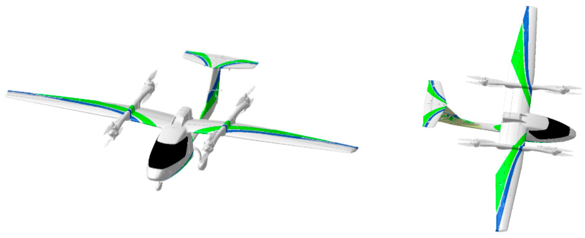
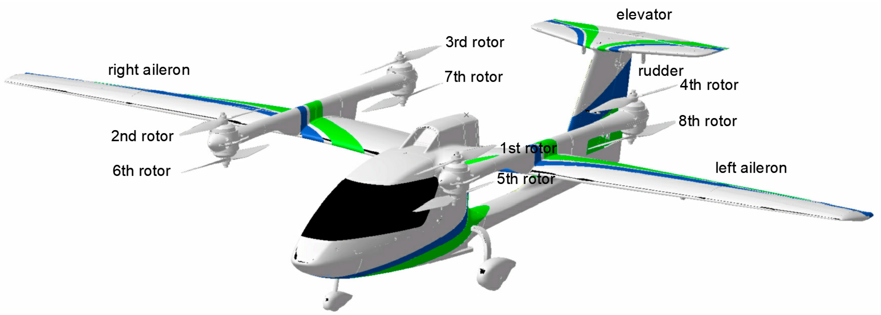
2.1. Platform Design and Operating Principle

The ET120 has the characteristics of multi-rotor vertical takeoff and landing and fixed-wing long-endurance flight. The layout of the platform is shown in Figure 2, and the geometric parameters are shown in Table 1. The advantages of the platform design are as follows:
(1)
In the hover mode, no additional trimming torque is required, because the acting point of the resultant lift is located at the center of gravity (CG).
(2)
The redundant design of the rotor power system enables the aircraft to have emergency landing capability in the case of a single rotor failure.
(3)
The rotor power system is electric, green, environmentally friendly and sustainable.
(4)
The high T-tail layout reduces the aerodynamic interference of the rotor to the elevator.
The ET120 has two power systems: the hover power system and the propulsion power system. The hovering system is powered by four pairs of coaxial twin-rotor motors mounted vertically on the wing body. The propulsion power system consists only of a rotor mounted horizontally behind the nacelles to provide fixed-wing cruising power.
The ET120 has two control modes: hovering and propulsion. The vertical motion is controlled by the total speed of the hovering rotors n v in the hovering mode and is controlled by the deflection of the elevator δ e in the propulsion mode, as shown in Figure 3a. Longitudinal motion is achieved by attitude control in the hovering mode (through the speed difference n θ of four hovering propellers in front of and behind each other to provide forward and backward acceleration) and is controlled by the propeller and elevator in the fixed-wing mode, as shown in Figure 3b. Lateral motion in the hovering and propulsion modes is determined by the speed difference n ϕ of the left and right rotors and aileron deflection δ a , respectively, as shown in Figure 3c. The control of the heading motion is the speed difference n ϕ of two groups of rotors in forward and reverse rotation and rudder deflection δ r , as shown in Figure 3d.
The virtual input vector is U = [ n v , n ϕ , n θ , n φ , n 9 , δ e , δ a , δ r ] T , and the actual input vector is U a = [ n 1 c , n 2 a , n 3 a , n 4 c , n 5 a , n 6 c , n 7 c , n 8 a , n 9 , δ e , δ a , δ r ] T , where n k * ( k = 1 , 2 , 8 ) represents the speed of each hovering rotor, n 9 is the speed of the propulsion rotor, * c , a represents the direction of rotor rotation, ‘c’ is clockwise and ‘a’ is anticlockwise. The relation between the actual input and the virtual input can be expressed as:
U a = R U
where R is a mixed matrix:
R = R 1 R 2 R 3 ,   R 1 = 1 1 1 1 1 1 1 1 1 1 1 1 1 1 1 1 1 1 1 1 1 1 1 1 1 1 1 1 1 1 1 1 ,   R 2 = 1 ,   R 3 = 1 1 1

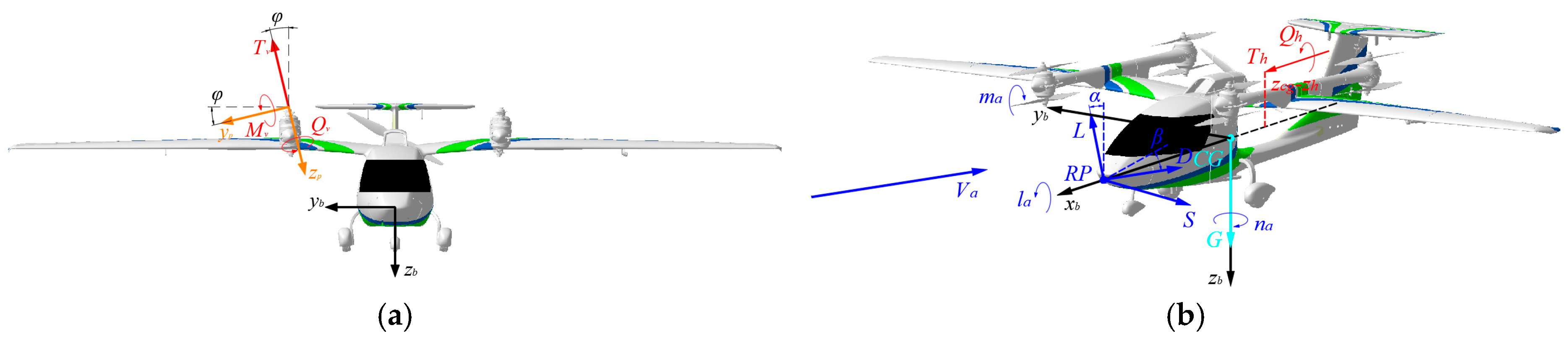
2.2. Aircraft Dynamics Modeling

2.2.1. Aerodynamic Model

The forces acting on the vehicle are the lift, drag and side force, and the moments acting on the vehicles are the rolling moment, pitching moment and yawing moment.
L = 0 . 5 C L ρ V t 2 S D = 0.5 C D ρ V t 2 S S = 0.5 C S ρ V t 2 S l a = 0.5 C l ρ V t 2 S b m a = 0.5 C m ρ V t 2 S c n a = 0.5 C n ρ V t 2 S b
where ρ is the air density; V t is the airspeed; S , b , c are the reference area, reference span and reference chord length, respectively; and C L , C D , C S , C l , C m , C n are the aerodynamic coefficients of L , D , S , l a , m a , n a , respectively.

2.2.2. Analysis of Force and 6-DOF Functions

By converting the aerodynamic forces L , D and S from the wind frame to the body frame, the forces projected onto the x b , y b , z b axes, respectively, can be expressed as follows:
F x = D cos α cos β S cos α sin β + L sin α G sin θ + T 9 F y = D sin β + S cos β + G sin ϕ cos θ + k = 1 8 T k sin φ k F z = D sin α cos β sin α sin β L cos α + G cos ϕ cos θ k = 1 8 T k cos φ k
where α and β are the angle of attack and the angle of the sideslip of the ET120, and φ k is the camber angle of the k -th rotor, as shown in Figure 4a.
The overall moments acting on the ET120 can be constructed as:
l = l a k = 1 8 T k sin φ k ( z k z c g ) i = 1 8 T k cos φ k ( y k y c g ) + Q 9 m = m a + m c g + k = 1 8 T k cos φ k ( x k x c g ) + k = 1 8 M y k cos φ k k = 1 8 Q k sin φ k n = n a + n c g + k = 1 8 T k sin φ k ( x k x c g ) + k = 1 8 Q k cos φ k + i = 1 8 M y k sin φ k
where x k , y k , z k are the coordinates of the k-th rotor in the body frame; l a , m a , n a are the aerodynamic moments; x r , y r , z r and x c g , y c g , z c g are the aerodynamic reference point and the CG in the body frame, respectively; and m c g , n c g are additional moments caused by the inconsistency of the aerodynamic reference x r , y r , z r and the CG x c g , y c g , z c g as well as the thrust line of the propulsion rotor and the CG x c g , y c g , z c g , which can be expressed as follows:
m c g = L cos α + Y sin α sin β + D sin α ( x r x c g ) T 9 ( z 9 z c g ) n c g = ( Y cos β D sin β ) ( x r x c g )
Developed based on Newton’s Second Law, the 6-DOF translation and the rotation functions of the ET120 can be expressed as follows:
u ˙ = v r w q + F x / m g v ˙ = w p u r + F y / m g w ˙ = u q v p + F z / m g l = I x p ˙ + ( I z I y ) q r I z x ( p q + r ˙ ) m = I x q ˙ + ( I x I z ) r p + I z x ( p 2 r 2 ) n = I x r ˙ + ( I y I x ) p q + I z x ( q r p ˙ )
where u , v and w are the velocities in the body frame; m g represents mass; I x , I y and I z are inertial moments; and I x y , I y z and I z x are inertial products.
The kinematical function of the ET120 can be written as
x ˙ g = u cos θ cos ψ + v ( sin θ sin ϕ cos ψ cos ϕ sin ψ ) + w ( sin θ cos ϕ cos ψ + sin ϕ sin ψ ) y ˙ g = u cos θ sin ψ + v ( sin θ sin ϕ sin ψ + cos ϕ cos ψ ) + w ( sin θ cos ϕ sin ψ sin ϕ cos ψ ) h ˙ = u sin θ v sin ϕ cos θ w cos ϕ sin θ ϕ ˙ = p + tan θ ( q sin ϕ + r cos ϕ ) θ ˙ = q cos ϕ r sin ϕ ψ ˙ = ( q sin ϕ + r cos ϕ ) / cos θ
where x g , y g and h are positions in the inertial frame, and ϕ , θ and ψ are the roll, pitch and yaw angle, respectively.

3. Control Logic

The eVTOLs usually have similar dynamic characteristics due to the similar design of aerodynamic layouts and control actuators. Even though the study object of this work is the ET120 vehicle, the application can still be applied in vehicles that have similar dynamic characteristics. Since the aerodynamic characteristics experience abrupt changes when the dynamic pressure varies, eVTOLs have dynamic characteristics that vary significantly between different flight modes. For instance, the vehicle has a normal fixed-wing dynamic response under the cruise speed, where the typical fixed-wing phugoid and short phase modes exists, and the short phase mode becomes unstable when the airspeed is low. Usually, a control stability augmentation system is implemented to obtain a desired closed-loop dynamic response.

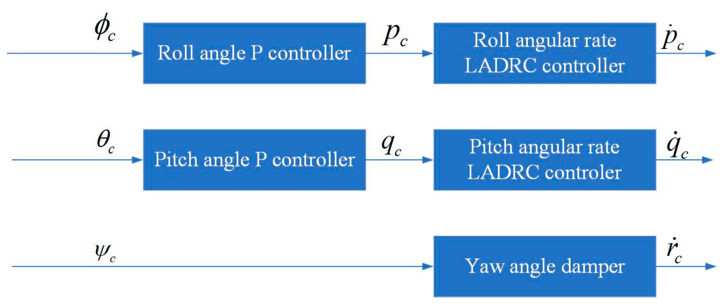
3.1. Stability Augmentation System

The stability augmentation system focuses on inner loop stabilization, which refers to the angular rate loop and the attitude angle loop, the task of which is to realize a precise track to the angular rate command and to reject the uncertainties and disturbances of the model, as shown in Figure 5.
Active disturbance rejection control (ADRC) is a fast and robust control theory which has been largely applied in aerospace control engineering. Since eVTOL vehicles have significant discrepancies between different flight modes, it is challenging to ensure a precise model for control design. Thus, this work applies the LADRC method to design the inner loop stability augmentation system. LADRC is a robust linear control algorithm which serves for single-input single-output (SISO) systems, and the control plant in this work is the ET120 vehicle, which is a multiple-input multiple-output (MIMO) system. The reason why this algorithm can be applied in such plant is that the MIMO system can be decoupled into a composition of a series of SISO systems. As shown in Figure 5, the control channels are specially designed, where the controls of each channel are relatively independent, and only one control input is given in each channel.
Typically, the LADRC controller is composed of a PD control combination and a linear extended state observer, whose tasks are tracking the commands and rejecing the disturbances, respectively. Since the control stability augmentation systems are similar in the roll, pitch and yaw channels, this work takes the pitch channel stability augmentation system for instructions.

3.1.1. LADRC Angular Rate Controller

The structure of the pitch angular rate channel LADRC controller is given in Figure 6, which consists of a linear extended state observer and a PD tracking combination.
The linear extended state observer is used to observe the error and to compensate for it, and the mathematical expressions of the LESO is given as:
e 1 = z 1 q z ˙ 1 = z 2 β 01 e + b 0 q ˙ c z ˙ 2 = β 02 e 1
where e is the error, z 1 is the estimation of the pitch angular rate, z 2 is the estimation of the pitch angular acceleration, q ˙ c is the pitch angular rate command and β 01 , β 02 and b 0 are the gain parameters.
The observed errors are then fed into the PD control combinations to obtain the desired pitch angular rate commands:
q ˙ c = ω q ( q c q ) + z 2
where ω q is the bandwidth of the pitch angular rate channel.

3.1.2. Attitude Stabilizer

With the aforementioned LADRC angular rate controller, the model tracks the angular rate command excellently; thus, the angular rate and its command can be treated as a proportional relationship. The outer attitude angle loop can be easily designed using a proportional controller to stabilize the vehicle.
The attitude angle is defined in the ground axis, and the control usually acts on the vehicle body frame. Therefore, the first step is to convert the attitude command to the body frame by Equation (8), and with simple calculations, the angular rates in the body frame can be written as:
p = ϕ ˙ tan θ ( q sin ϕ + r cos ϕ ) q = θ ˙ cos ϕ + r tan ϕ r = ψ ˙ cos θ cos ϕ q tan ϕ
The attitude control is a simple proportional control which can be written as:
ϕ ˙ c = k p ϕ ( ϕ c ϕ ) θ ˙ c = k p θ ( θ c θ )
where k p ϕ is the proportional gain of the roll angle loop and k p θ is the proportional gain of the pitch angle channel.
By substitute Equation (12) into Equation (11), the roll and pitch angular rate command becomes:
p c = k p ϕ ( ϕ c ϕ ) tan θ ( q sin ϕ + r cos ϕ ) q c = k p θ ( θ c θ ) cos ϕ + r tan ϕ
For the yaw channel, a yaw damper is applied with a high frequency pass filter weakening the steady yaw angular rate signal that derives from stable turning, which is expressed as:
r ˙ c = k p r τ s τ s + 1
where k p r is the damper proportional gain, and τ is the damper time constant.

3.1.3. Control Allocator

Since ET120 has different flight modes, one of the major differences between them is the control efficiency of the actuators. When the airspeed is low, the efficiency of the hovering rotors is high, and the aerodynamic control surfaces are low. When the airspeed is high, it is the opposite. The control allocator is designed based on the control efficiency to obtain the most efficient action of the actuators and to track the angular acceleration command precisely with a natural and automatic transition between each channel.
The mathematical expression of the control allocators is given as:
δ e = q ˙ c M max δ e min n θ = q ˙ c M max n θ max δ a = p ˙ c L max δ a min n ϕ = p ˙ c L max n ϕ max δ r = r ˙ c N max δ r max n φ = r ˙ u c N max n ϕ max
where M max , L max and N max are the maximum control efficiencies of the pitch, roll and yaw channels, which can be described as:
M max = η δ e M ¯ δ e δ e min + M ¯ n θ n θ max L max = η δ a L ¯ δ a δ a min + L ¯ n ϕ n ϕ max N max = η δ r N ¯ δ r δ r max + N ¯ n φ n φ max
where M ¯ n θ , L ¯ n ϕ and N ¯ n φ are the pitch, roll and yaw control efficiencies of the per-unit multi-rotor inputs; M ¯ δ e , L ¯ δ a and N ¯ δ r are the pitch, roll and yaw angular acceleration of the per-unit aero-surface deflection; and η δ e , η δ a and η δ r are the gain-scheduling factors determined by the dynamic pressure, given as:
η δ e , δ a , δ r = 0 0 V t V 1 V t V 1 V 2 V 1 2 V 1 V t V 2 1 V 2 V t
where V 1 is the transitional airspeed given as 15 m/s, and V 2 is the cruise airspeed given as 35 m/s.

3.1.4. Control Parameter Design

The parameters to design include the LESO gains β 01 , β 02 , b 0 and the pitch angular rate channel bandwidth ω q . Typically, b 0 and ω q are designed by the model dynamic characteristics, which are based on time-scale separation principles. This work sets them as b 0 = 1 , ω q = 1.5 .
The core of the parameter design of LADRC controllers is the design of the LESO error gains β 01 and β 02 , the aims of which are to let the LESO converge rapidly. From the state space function of the LESO (Equation (9)), the characteristic function of LESO can be rewritten as:
z ˙ = A z + B y
where z = z 1 z 2 , y = q q c , A = β 01 1 β 02 0 , B = β 01 b 0 β 02 0 .
To let the LESO converge, the matrix A should have negative eigenvalues λ , which can be easily expressed by its eigen functions:
λ 2 + β 01 λ + β 02 = 0
Let
β 01 = 2 ω L E S O β 02 = ω L E S O 2
Then, if ω L E S O is positive, the eigenvalues of A are − ω L E S O , which let the LESO converge with a frequency of ω L E S O . With the time-scale separation principle, ω L E S O is designed as ω L E S O = 6 , which is four times ω q . The control parameters in each channel are given in Table 2:

3.2. Simplified Vehicle Operation

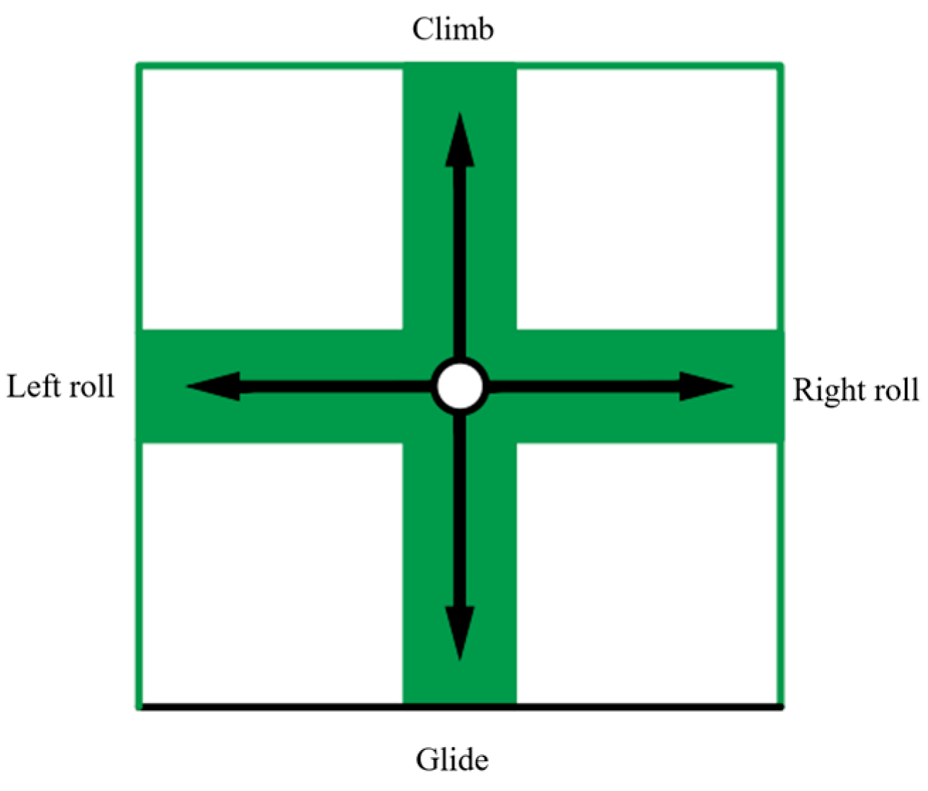
3.2.1. Stick Definition

Typically, there exist two sticks in aerial vehicles, regardless of whether they are in helicopters or fixed-wings, and it is the same for eVTOLs. However, the function for the sticks is different between different aerial vehicles. For example, the throttle lever in fixed-wings usually controls the throttle of the propulsion engine, which deals with the speed, and for the helicopters, the speed stick is replaced by the collective-pitch lever that controls the rate of the climb of the helicopters. Consequently, no consistent control principles for vehicles have both multi-rotor modes and fixed-wing modes like eVTOLs. Simplified vehicle operation is used to deal with this issue, which is essentially a designed semi-autonomous control principle that has a consistent operation principle for pilots inside the whole flight envelope, regardless of the flight modes that are decided by the airspeeds. Since the pedal always controls the yawing motion of the vehicles both for multi-rotors and fixed-wings, this issue is especially for the control stick and the speed stick.
  • The control stick response design
The control stick is able to be pushed forward or backward and left or right, both for multi-rotors and fixed-wings. A reasonable stick design should keep in mind the common sense of the pilots, including for helicopters and fixed-wings. The stick responses are specially designed, as depicted in Figure 7, and the control outputs of the control stick are given in Table 3.
For both helicopters and fixed-wings, the left and right stick response is the rolling motion of the vehicle, so the left and right control response of the control stick is designed to be the rolling motion of the vehicle. Notice that, in the hovering mode, the roll angle only brings about the y-axis displacement, which has the same control logic with the speed stick, so the response of the left and right motion of the control stick has a lower priority compared to the speed stick in the hovering and transition phase.
For the forward and backward stick response, it diverges for for the pilots of helicopters and fixed-wings. For fixed-wing pilots, to push the stick is to pitch down to decrease altitude, whereas for helicopter pilots, to push the stick is to pitch down for forward acceleration. Thus, a consistent operation principle should be designed for eVTOL vehicle pilots. This work designs the forward and backward control stick response to be the rate of climb, since pulling the stick to climb is the consensus of both fixed-wing and helicopter pilots. The difference only exists in which stick to use: fixed-wing pilots use the control stick, whereas helicopter pilots use the collective-pitch stick.
  • The speed stick response design
Distinguished from the control stick, the dimensions of freedom of the speed stick are one in the fixed-wing mode, which is pushing forwards or pull backwards, and two in the multi-rotor mode, which can be pushed left or right additionally. This phenomenon derives from the difference in the operation principles between helicopters and fixed-wings. For helicopters, the left or right motion of the speed stick generates cyclic pitch commands and drives the helicopter along the y-axis without impacting other axis motions, and for fixed-wings, the y-axis motion can only be realized by sideslip, which is not expected in most flight missions. Therefore, a mode switch based on airspeed should be designed for the speed stick, as illustrated in Figure 8 and Table 4.
For the forward or backward motion of the speed stick, it is designed to control the forward airspeed of the vehicle. This design not only reflects the common sense of the pilot but also can be used to judge the flight mode that depends on the flight airspeed and to change the dimension of freedom for the sticks, and the operation mode of the speed stick is decided by the flight modes. Theoretically, when the flight airspeed is over the stall speed of the fixed-wing configuration, the flight mode turns to fixed-wing modes. However, when the flight airspeed is close to the left boundary of the fixed-wing flight envelope, the angle of attack is in the reverse control region, which is dangerous, and the uncertainties that exist in real flight make the stall speed not exactly the calculated one. Therefore, the designed airspeed to switch to the fixed-wing mode is 1.2 times the calculated stall airspeed.
For the left and right motion of the speed stick, the SVO design is to let it control the y-axis translation motion of the vehicle. Notably, this operation can only be executed when the hovering rotor works, i.e., in the hovering mode and transition mode.

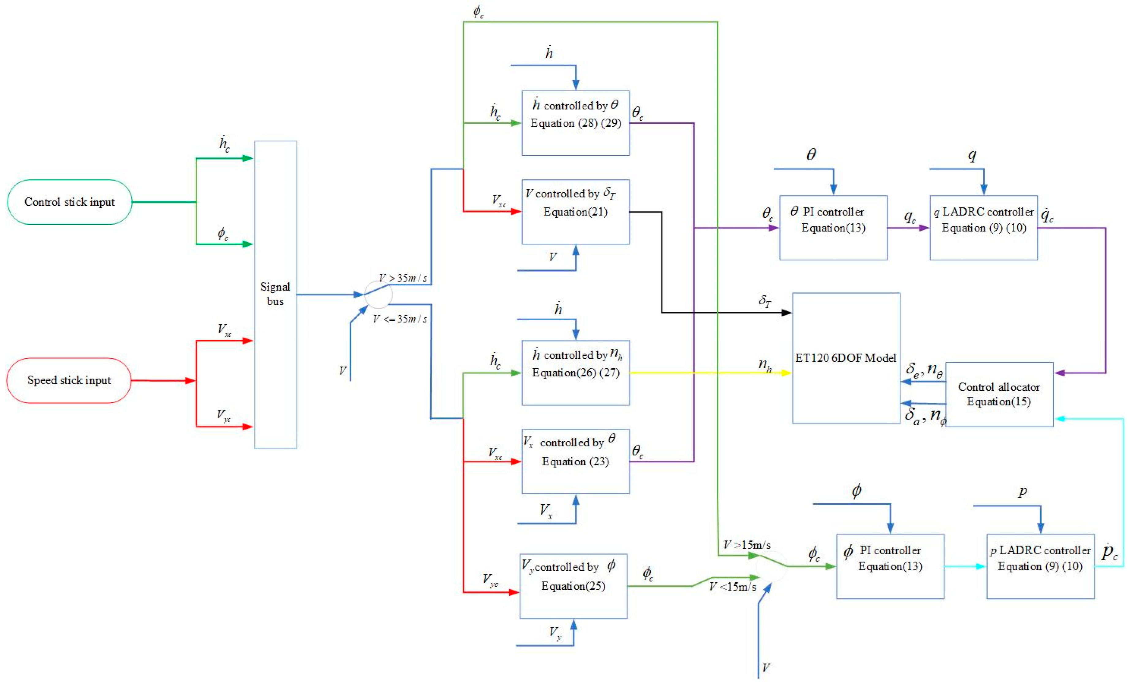
3.2.2. SVO Control Architecture

With the SVO principle designed, a supporting control architecture is designed for principle implementation, as shown in Figure 9.
  • Airspeed control
In the fixed-wing and transition mode, the forward x-axis airspeed is controlled by the propulsion rotor throttle δ T , as the aerodynamic control surfaces are efficient enough to balance the additional moments of the propulsion rotors, which is realized by a simple PI controller:
δ T = k p v ( V d V ) + k I v ( V d V ) d t T max m
where k p v and k I v are the proportional gain and integral gain for airspeed channels.
In the hovering mode, the airspeed is controlled by the x-axis components of the hovering rotors, which terminate the pitch angle. When the pitch angle is small, it is approximately equal to
a x = g sin θ g θ
The speed control is still controlled by a simple PI controller, and only the forward acceleration command is converted to the pitch angle by Equation (1):
a x c = k p v ( v x c v x ) + k i v ( v x c v x ) d t θ c = k p v ( v x c v x ) + k i v ( v x c v x ) d t g
For the y-axis velocity control, it is similar to that of the x-axis, but the realization is based on roll angle, as:
a y = g sin ϕ g ϕ
a y c = k p v ( v y c v y ) + k i v ( v y c v y ) d t ϕ c = k p v ( v y c v y ) + k i v ( v y c v y ) d t g
  • rate of climb control
For the hovering mode, the rate-of-climb commands are first converted to z-axis acceleration commands by a PI controller and are then converted to hovering rotor throttle commands:
a z c = k P h ( h ˙ c h ˙ ) + k I h ( h ˙ c h ˙ ) d t
n h = m a z c T h max
For the fixed-wing mode, the rate-of-climb commands are converted to pitch angle commands by the flight path angle commands:
γ c = arctan ( h ˙ c V g )
θ c = k P γ ( γ c γ ) + k I γ ( γ c γ ) d t
where V g is the ground velocity, and k P γ and k I γ are the proportional gain and integral gain of the flight path angle channel.
For the transitional mode, the rate of climb commands are allocated to z-axis acceleration commands and climb angle commands by a linear relationship by airspeed:
h ˙ c n h = V 2 V a V 2 V a h ˙ c h ˙ c γ = V a V 1 V 2 V a h ˙ c
where h ˙ c n h and h ˙ c γ are the climb rate commands allocated to hovering rotor speed channels and climb angle channels, V 1 and V 2 are the transitional speed and cruise speed given by Equation (17) and V a is the processed airspeed, given as:
V a = V 1 , V < V 1 V , V 1 V V 2 V 2 , V > V 2

4. Takeoff and Acceleration Strategy

The core of the vertical takeoff and acceleration problem of eVTOLs is the management of the propulsion system and hovering rotor system, during which the phases, altitude and airspeed are controlled by different principles. When the airspeed is low, the control efficiency of the aerodynamic control surfaces is insufficient to balance the pitch moments caused by the displacement of the propulsion thrust, and the airspeed should be controlled by the forward components of the hovering rotor system. Although the airspeed is close to the cruise airspeed, the hovering rotor system has no efficiency to hold the altitude of the vehicle and balance the aerodynamic drag, and the vehicle should be in the fixed-wing mode with the cruise states. The transition from thrust borne to lift borne is a thorny issue. This work designs four-stage control logic to realize smooth acceleration from zero airspeed to cruise speed without abrupt changes in the altitude and attitudes.
The flowchart of the designed takeoff and acceleration strategy is given in Figure 10.
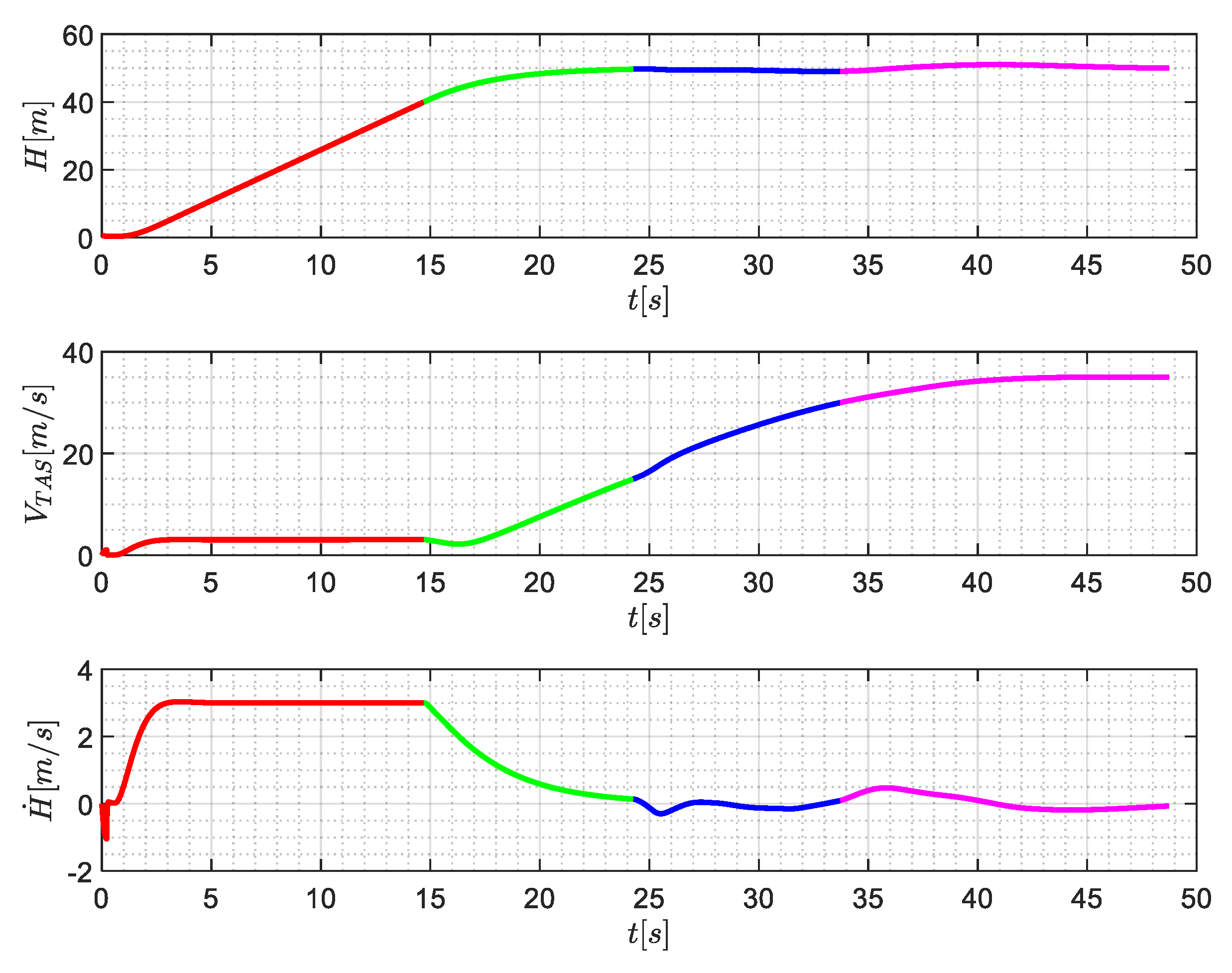
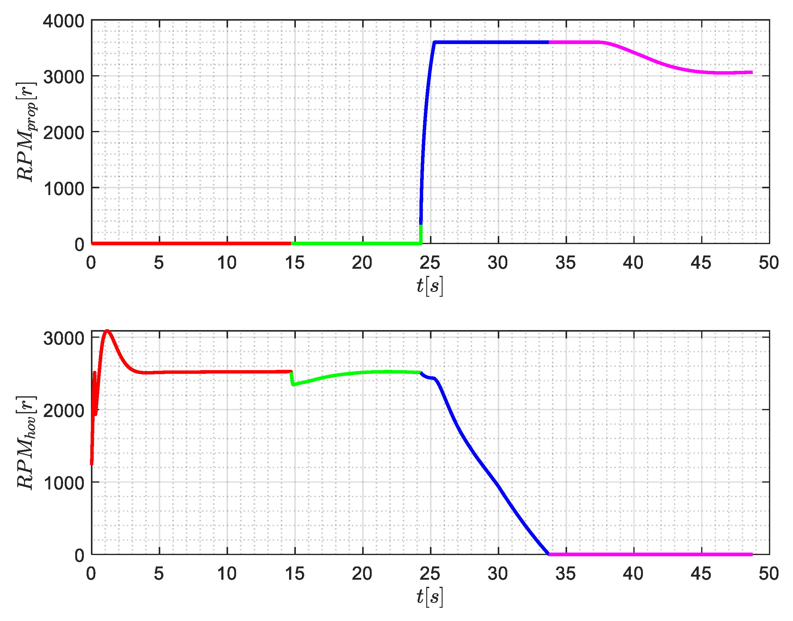
  • Stage I: Vertical takeoff
In this stage, the vehicle takes off vertically to the cruise altitude, where the altitude control is realized by the hovering rotors. The attitude of the vehicle is controlled to be zero in each channel.
  • Stage II: Low-speed acceleration
In this stage, the aerodynamic control surfaces are inefficient to realize attitude stability augmentation and to balance the propulsion system moments. The acceleration is realized by the forward components of the hovering system, which is virtually controlled by the pitch angle. The altitude is held by the vertical components of the hovering system, which is achieved by the rotor speed control.
  • Stage III: High-speed acceleration
In this stage, the aerodynamic control surfaces can balance the pitch moments caused by the propulsion system to some extent. The propulsion system can be activated gradually to balance the increasing aerodynamic drag, and due to the aerodynamic lift, the vehicle climbs up. Therefore, the rate-of-climb command is allocated to the hovering rotor speed and to the flight path angle, which terminates to the pitch angle control. The forward airspeed in this phase is controlled by the propulsion system.
  • Stage IV: ‘Cruise’
In this stage, the vehicle has enough airspeed to fly in the fixed-wing mode, and the attitude of the vehicle is not in the cruise state. For this stage, the attitude control is completely realized by the aerodynamic forces, and the altitude is allocated to the flight path angle only. The hovering system is cut off, and airspeed is controlled by the propulsion system independently.

5. Simulation

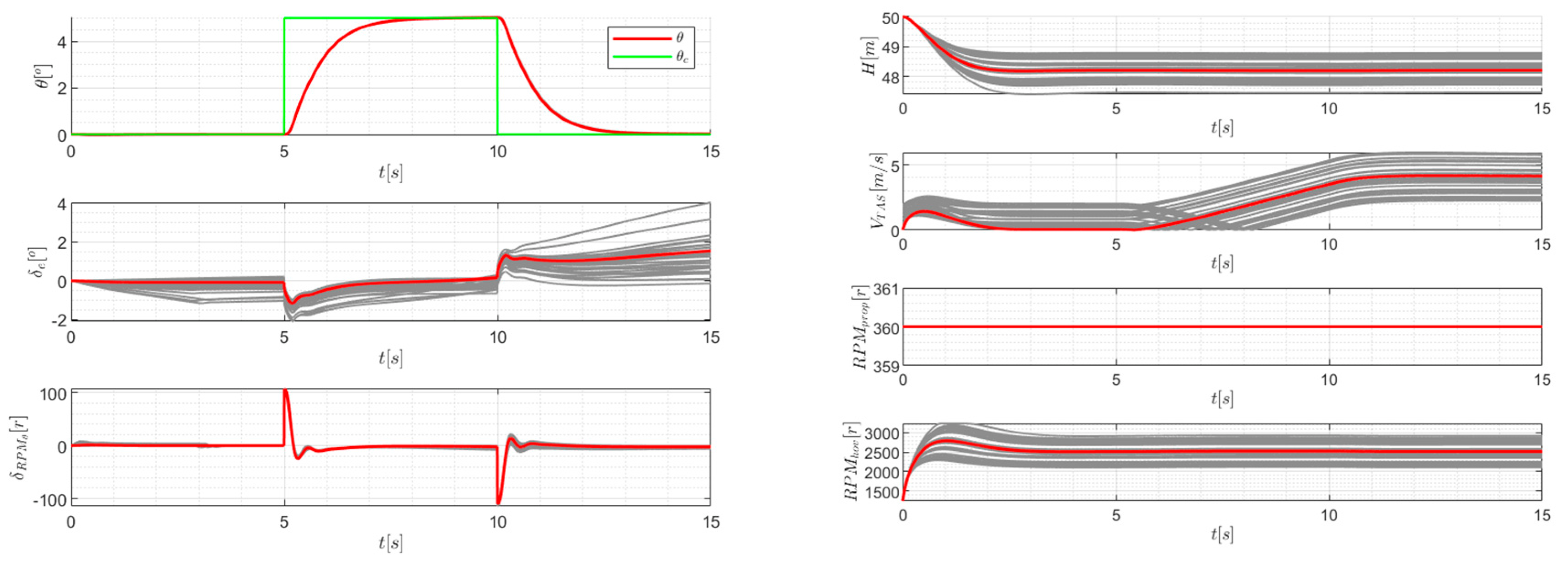
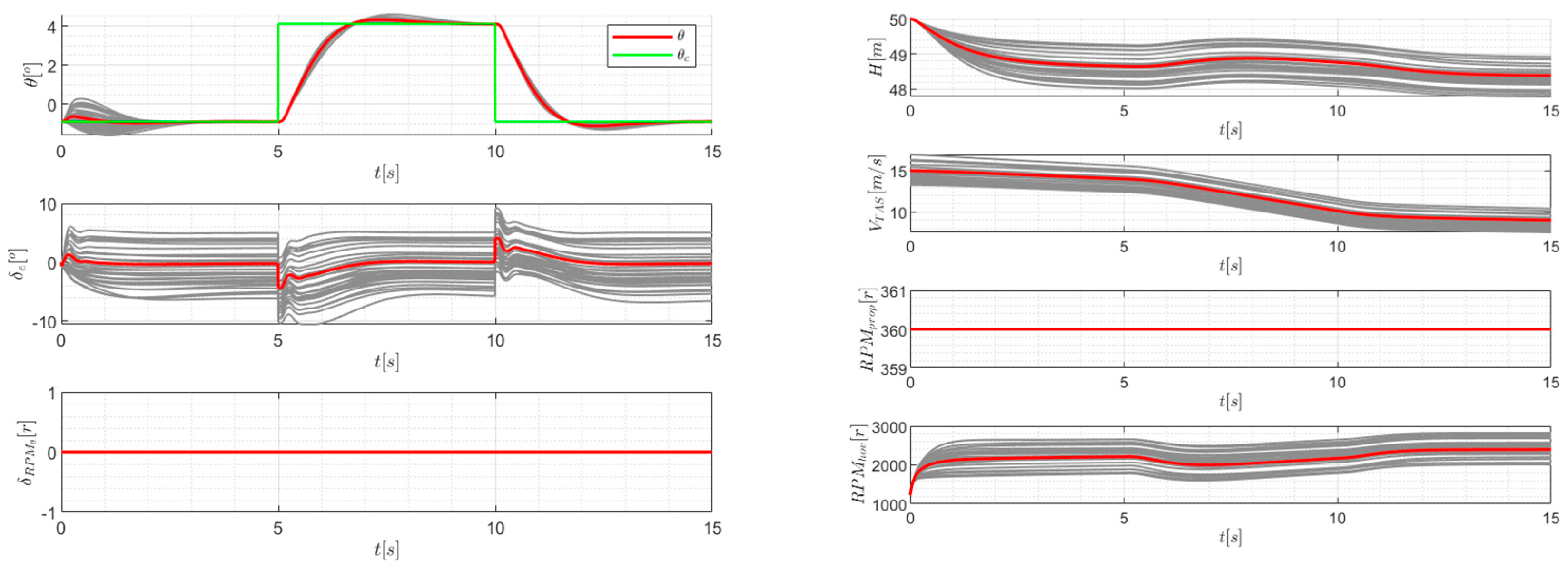
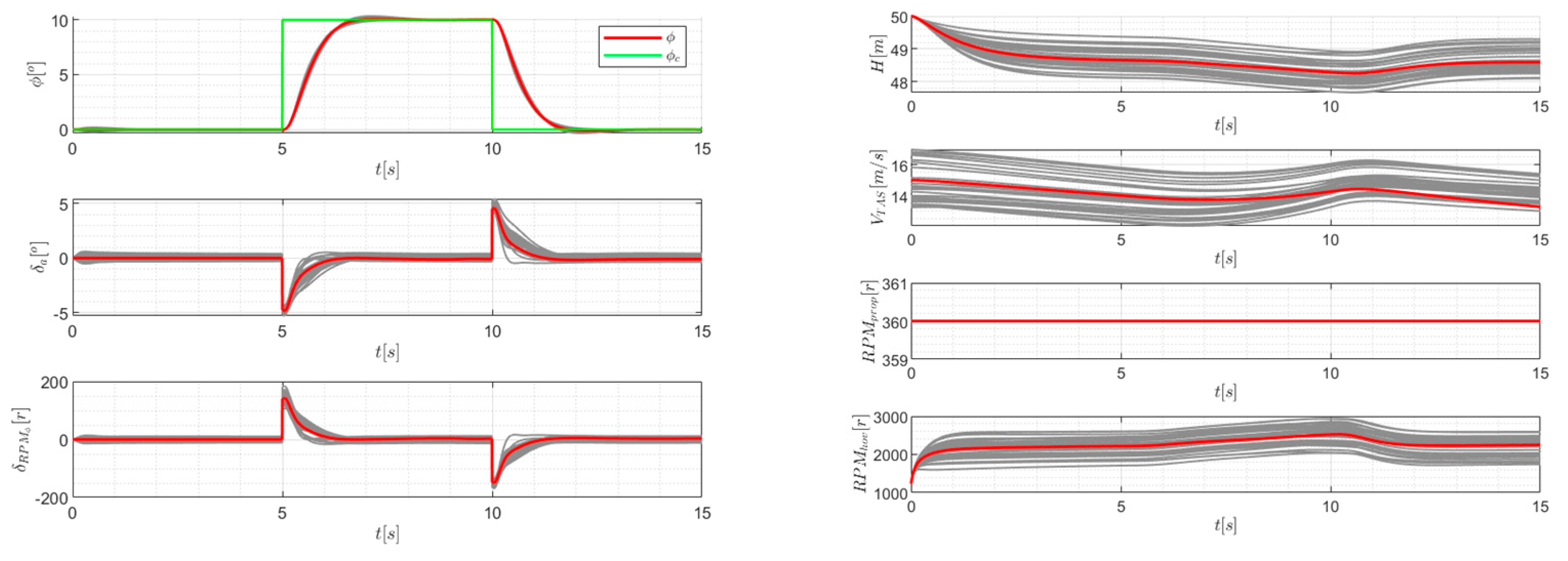
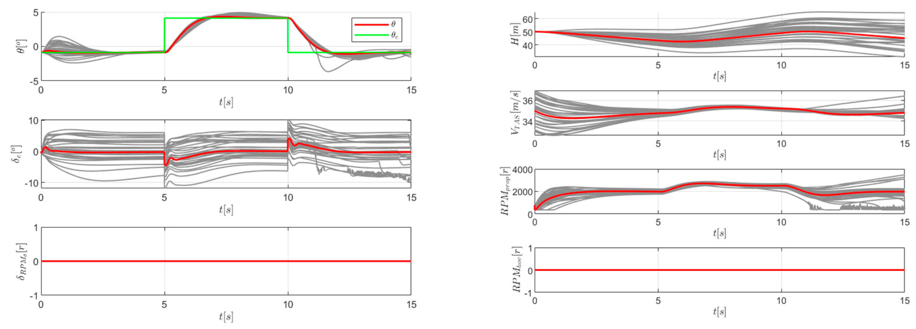
5.1. Inner Loop Monte Carlo Robustness Verification

The base of the control system in this work is the inner loop LADRC controller. Usually, Monte Carlo simulations are applied to verify the robustness performance of controllers, whose principles are simple but practical. Monte Carlo simulations take all disturbances and uncertainties into consideration by setting the perturbation ranges of all model parameters, choosing them randomly and feeding them into the simulation systems, which is a direct and nonlinear robustness verification method almost suitable for all control systems. The perturbation of the models is given in Table 5:
The perturbations are set to 20% for all parameters, as in practice, the perturbations derive from the uncertainties and errors of the state measurements and model parameters, which usually have an error tolerance less than 10%. With a safety factor of two, we let the tolerance be the double of the standard. The disturbances of the external environments are included by converting them into internal uncertainties of the model, as the impact of the external disturbances are mainly the change in flow angle, and leading to the aerodynamic characteristics finally changing. Monte Carlo simulations cover almost all possible undesired situations, which is not only meaningful for the inner loop design but also for the emergency disposal scheme establishment.
With the perturbations, the tracking performance of the controller in the pitch and roll channels in the typical states of the multi-rotors and the transitional and fixed-wing modes are presented below, where the red lines indicate the nominal state, and grey lines indicate the perturbed state. In Figure 11, Figure 12, Figure 13, Figure 14, Figure 15 and Figure 16, the subscript c represents the command, θ and ϕ are the angle of pitch and angle of roll, δ e and δ a are the deflection angle of the elevator and ailerons, respectively, δ R P M θ and δ R P M ϕ are the speed difference of the hovering rotors for pitch control and roll control, respectively, H is the altitude, V T A S is the true airspeed and R P M p r o p and R P M h o v are the speed of the propulsion rotors and hovering rotors.
Clearly, from Figure 11, Figure 12, Figure 13, Figure 14, Figure 15 and Figure 16, the tracking performance in both roll and pitch channels are excellent, and the states are converged with little deviation under any perturbations. Moreover, the control actuators have a large enough margin to resist performing large maneuvers, and the altitude and airspeed views change little. The rising time of the pitch angle and roll angle are almost the same under any flight mode, which reflects consistent dynamic responses. It is shown that, under the given perturbations, the inner loop controller tracks the commands perfectly with consistent dynamic characteristics in pitch and roll channels, regardless of the flight modes.
Moreover, to show the robustness performance of the LADRC controller, a fixed-wing mode pitch channel comparison to the L1 adaptive controller in our previous work [19] is given in Figure 17.
The nominal state responses are tuned to have similar responses for an equal state comparison, with the perturbation states set as the same 20%. Compared to Figure 13, the nominal states are almost the same, where the rising time and steady state error are tuned to be equal. However, the differences occur at the perturbation states, and the L1 adaptive controller requires a larger control for actuators to compensate the model uncertainties. In some states, the control requirements touch the physical boundaries. Moreover, it takes more time for the L1 adaptive controller to converge to the stable state from perturbed states, as the pitch angle results show.
It can be concluded that the LADRC controller has a better robustness performance, where the actuator requirements are less than those of our previous work, and the uncertainty compensation is more rapid than the L1 adaptive controller, when the nominal state performance is similar.

5.2. Vertical Takeoff and Acceleration Mission

The simulation results of the aforementioned takeoff and acceleration strategy are given in Figure 18, Figure 19, Figure 20 and Figure 21.
In the presented figures, the red lines indicate the vertical takeoff phase, green indicates low-speed acceleration, blue indicates high-speed acceleration and pink indicates fixed-wing cruising. Firstly, Figure 18 shows the time history of altitude airspeed and the rate of climb, from which the following conclusions can be drawn:
The control system perfectly controls the rate of climb, regardless of which logic to use. In the vertical takeoff phase, the climb rate is kept to 3 m/s, which is the upper boundary set previously, which is also reflected by Figure 21, in which the control stick is pulled to the max to generate this command. In the transitional phase (green and blue lines), the altitude rises from the safety altitude 40 m to the cruise altitude 50 m, and it is kept well at 50 m throughout the acceleration process. The altitude experiences an oscillation amplitude of ± 2 m (2% of the whole), since the altitude control logic is changed from rotor speed control to pitch angle control, and the velocity ranges from a transition airspeed of 15 m/s to a cruise airspeed of 35 m/s. This oscillation is allowed in engineering, and it converges with the time. The rate of climb is kept low, specifically under a 0.5 m/s absolute value, when the vehicle achieves the cruise altitude, and this level of climb rate is also friendly to pilots.
Figure 19, Figure 20 and Figure 21 reveal the control logic of the takeoff and acceleration logic. At the end of the vertical takeoff phase, the pitch angle experiences a significant decrease, which is caused by the acceleration command (given by the speed stick, as is shown in Figure 20). Then, when the airspeed reaches 15 m/s, the pitch angle rises as the hovering rotor speed decreases. This phenomenon occurs due to the switch of the altitude control logic, and when the flight enters high-speed acceleration, the altitude is controlled by the pitch angle instead of the hovering rotor speed. The propulsion rotor speed increases to control the forward speed, as in this phase, the pitch angle is occupied for altitude control.
In the whole process, the stick input is very simple with the SVO logic activated, as shown in Figure 20, since the mode switch is self-activated by the control system, and the pilot is free of complicated stick operation, which definitely relieves the workload of the pilots. The state of the vehicle is controlled inside a safe envelope, which is realized by the stick output limitation. The control system equipped with SVO logic satisfies the handling quality requirements and safety indexes.

6. Conclusions

In this work, a practical vertical takeoff and acceleration strategy is developed for eVTOLs, which is realized by a simplified vehicle operation system based on the LADRC algorithm. The LADRC algorithm is sufficiently robust to reject at least 20% of disturbances and uncertainties of all modeling parameters, including the aerodynamic uncertainties and propulsion system uncertainties. The proposed vertical takeoff and acceleration strategy is able to switch from the multi-rotor mode to the fixed-wing mode smoothly, where the state, including the attitude angles, altitudes and airspeed, is controlled inside a safe envelope and rejects any abrupt variations, and the altitude can be held at a constant value (50 m) with small oscillations (under 5%), as shown in Figure 18. A SVO control system is developed, considering the operation rules for helicopters and fixed-wings, which makes a balance between the different operation principles between different flight modes. With the SVO control system equipped, the pilots can perform the proposed strategy with simple rules, where the stick input requirements are few, which means a light workload for the pilot. To conclude, the takeoff and acceleration strategy and SVO control system can be a reference for future manned eVTOL vehicle design.

Author Contributions

Data curation, Z.G., Z.Y., Z.W. and T.G.; Formal analysis, S.M.; Investigation, S.M., T.G. and C.Z.; Methodology, S.M. and Z.W.; Project administration, Z.Y. and C.Z.; Software, Z.G. All authors have read and agreed to the published version of the manuscript.

Funding

This research received no external funding.

Conflicts of Interest

The authors declare no conflict of interest.

References

  1. Courtin, C.; Burton, M.J.; Yu, A. Feasibility Study of Short Takeoff and Landing Urban Air Mobility Vehicles Using Geometric Programming. In Proceedings of the Aviation Technology, Integration, & Operations Conference, Atlanta, GA, USA, 25–29 June 2018; p. 70. [Google Scholar] [CrossRef]
  2. Mingkai, W.A.N.G.; Zhang, S.; Diepolder, J.; Holzapfel, F. Battery package design optimization for small electric aircraft. Chin. J. Aeronaut. 2020, 33, 2864–2876. [Google Scholar] [CrossRef]
  3. Thompson, E.L.; Taye, A.G.; Guo, W.; Wei, P.; Quinones, M.; Ahmed, I.; Biswas, G.; Quattrociocchi, J.; Carr, S.; Topcu, U.; et al. A Survey of eVTOL Aircraft and AAM Operation Hazards. In Proceedings of the AIAA AVIATION 2022 Forum, Chicago, IL, USA, 27 June–1 July 2022; p. 3539. [Google Scholar] [CrossRef]
  4. Thompson, D. Robust Control of an Evtol through Transition with a Gain Scheduling LQR Controller. Ph.D. Thesis, University of Maryland, College Park, MD, USA, 2020. [Google Scholar] [CrossRef]
  5. Raab, S.A.; Zhang, J.; Bhardwaj, P.; Holzapfel, F. Proposal of a unified control strategy for vertical take-off and landing transition aircraft configurations. In Proceedings of the 2018 Applied Aerodynamics Conference, Atlanta, GA, USA, 25–29 June 2018; p. 3478. [Google Scholar] [CrossRef]
  6. Dollinger, D.; Fricke, T.; Holzapfel, F. Control inceptor design for remote control of a transition UAV. In Proceedings of the AIAA Aviation 2019 Forum, Dallas, TX, USA, 17–21 June 2019; p. 3268. [Google Scholar] [CrossRef]
  7. Jones, M.; Perfect, P.; Jump, M.; White, M. Investigation of novel concepts for control of a personal air vehicle. In Proceedings of the American Helicopter Society 70th Annual Forum, Montréal, QC, Canada, 20–22 May 2014; p. 5. [Google Scholar] [CrossRef]
  8. Lombaerts, T.; Kaneshige, J.; Feary, M. Control concepts for simplified vehicle operations of a quadrotor eVTOL vehicle. In Proceedings of the AIAA Aviation 2020 Forum, Virtual Event, 15–19 June 2020; p. 3189. [Google Scholar] [CrossRef]
  9. Dollinger, D.; Reiss, P.; Angelov, J.; Löbl, D.; Holzapfel, F. Control inceptor design for onboard piloted transition vtol aircraft considering simplified vehicle operation. In Proceedings of the AIAA Scitech 2021 Forum, Virtual Event, 11–15 and 19–21 January 2021; p. 1896. [Google Scholar] [CrossRef]
  10. Ducard, G.J.; Allenspach, M. Review of designs and flight control techniques of hybrid and convertible VTOL UAVs. Aerosp. Sci. Technol. 2021, 118, 107035. [Google Scholar] [CrossRef]
  11. Saetti, U.; Enciu, J.; Horn, J.F. Flight Dynamics and Control of an eVTOL Concept Aircraft with a Propeller-Driven Rotor. J. Am. Helicopter Soc. 2022, 67, 153–166. [Google Scholar] [CrossRef]
  12. Smeur, E.J.; Chu, Q.; De Croon, G.C. Adaptive incremental nonlinear dynamic inversion for attitude control of micro air vehicles. J. Guid. Control Dyn. 2016, 39, 450–461. [Google Scholar] [CrossRef]
  13. Acquatella, P.; Falkena, W.; van Kampen, E.J.; Chu, Q.P. Robust Nonlinear Spacecraft Attitude Control using Incremental Nonlinear Dynamic Inversion. In Proceedings of the AIAA Guidance, Navigation, and Control Conference, Minneapolis, MN, USA, 13–16 August 2012; Volume 8, p. 4623. [Google Scholar] [CrossRef]
  14. Lombaerts, T.; Kaneshige, J.; Schuet, S.; Hardy, G.; Aponso, B.L.; Shish, K.H. Nonlinear dynamic inversion based attitude control for a hovering quad tiltrotor eVTOL vehicle. In Proceedings of the AIAA Scitech 2019, San Diego, CA, USA, 7–11 January 2019; p. 0134. [Google Scholar] [CrossRef]
  15. Yang, H.; Morales, R. Robust full-envelope flight control design for an eVTOL vehicle. In Proceedings of the AIAA Scitech 2021 Forum, Virtual Event, 11–15 and 19–21 January 2021; p. 0254. [Google Scholar] [CrossRef]
  16. Yun, W.J.; Jung, S.; Kim, J.; Kim, J.H. Distributed deep reinforcement learning for autonomous aerial eVTOL mobility in drone taxi applications. ICT Express 2021, 7, 1–4. [Google Scholar] [CrossRef]
  17. Ningjun, L.I.U.; Zhihao, C.A.I.; Yingxun, W.A.N.G.; Jiang, Z.H.A.O. Fast level-flight to hover mode transition and altitude control in tiltrotor’s landing operation. Chin. J. Aeronaut. 2021, 34, 181–193. [Google Scholar] [CrossRef]
  18. Wang, Z.; Mao, S.; Gong, Z.; Zhang, C.; He, J. Energy efficiency enhanced landing strategy for manned eVTOLs using L1 adaptive control. Symmetry 2021, 13, 2125. [Google Scholar] [CrossRef]
  19. Wang, Z.; Gong, Z.; Zhang, C.; He, J.; Mao, S. Flight Test of L 1 Adaptive Control on 120-kg-Class Electric Vertical Take-Off and Landing Vehicles. IEEE Access 2021, 9, 163906–163928. [Google Scholar] [CrossRef]
  20. Zheng, Q.; Gao, Z. On practical applications of active disturbance rejection control. In Proceedings of the 29th Chinese Control Conference, Kottayam, India, 22–23 March 2013; Volume 7, pp. 6095–6100. [Google Scholar]
  21. Gao, Z. Active disturbance rejection control: A paradigm shift in feedback control system design. In Proceedings of the 2006 American Control Conference, Minneapolis, MN, USA, 14–16 June 2006; Volume 6, p. 7. [Google Scholar] [CrossRef]
  22. Xili, Y.; Yong, F.; Jihong, Z. Transition flight control of two vertical/short takeoff and landing aircraft. J. Guid. Control Dyn. 2008, 31, 371–385. [Google Scholar] [CrossRef]
  23. Malpica, C.; Withrow-Maser, S. Handling qualities analysis of blade pitch and rotor speed controlled eVTOL quadrotor concepts for urban air mobility. In Proceedings of the VFS International Powered Lift Conference, San Jose, CA, USA, 21–23 January 2020; pp. 21–23. [Google Scholar]
  24. Wang, M.; Diepolder, J.; Zhang, S.; Söpper, M.; Holzapfel, F. Trajectory optimization-based maneuverability assessment of eVTOL aircraft. Aerosp. Sci. Technol. 2021, 117, 106903. [Google Scholar] [CrossRef]
Figure 1. Model diagram of ET120 aircraft.
Mathematics 10 03333 g001
Figure 2. Introduction of the ET120 aircraft platform.
Mathematics 10 03333 g002
Figure 3. The mechanical configuration and control principles of ET120. (a) Vertical motion control, (b) Forward motion and pitch channel control, (c) Lateral motion and roll channel control, (d) Yaw channel control.
Mathematics 10 03333 g003
Figure 4. Force analysis of ET120. (a) Definition of camber angle, (b) The analysis of force on the ET120 vehicle.
Mathematics 10 03333 g004
Figure 5. Stability augmentation system.
Mathematics 10 03333 g005
Figure 6. Pitch angular rate LADRC controller.
Mathematics 10 03333 g006
Figure 7. The control stick SVO principles.
Mathematics 10 03333 g007
Figure 8. The speed stick SVO principles.
Mathematics 10 03333 g008
Figure 9. SVO control architecture.
Mathematics 10 03333 g009
Figure 10. Vertical takeoff and acceleration strategy.
Mathematics 10 03333 g010
Figure 11. Multi-rotor mode for Monte Carlo simulations in the pitch channel.
Mathematics 10 03333 g011
Figure 12. Transition mode for Monte Carlo simulations in the pitch channel.
Mathematics 10 03333 g012
Figure 13. Fixed-wing mode for Monte Carlo simulations in the pitch channel.
Mathematics 10 03333 g013
Figure 14. Multi-rotor mode for Monte Carlo simulations in the roll channel.
Mathematics 10 03333 g014
Figure 15. Transition mode for Monte Carlo simulations in the roll channel.
Mathematics 10 03333 g015
Figure 16. Fixed-wing mode for Monte Carlo simulations in the roll channel.
Mathematics 10 03333 g016
Figure 17. Fixed-wing mode for Monte Carlo simulations in the pitch channel using L1 adaptive control.
Mathematics 10 03333 g017
Figure 18. Time history of altitude, airspeed and rate of climb.
Mathematics 10 03333 g018
Figure 19. Time history of angle of pitch, elevator deflection angle and differential rotor speed for pitch.
Mathematics 10 03333 g019
Figure 20. Time history of hovering rotor speed and propulsion rotor speed.
Mathematics 10 03333 g020
Figure 21. Time history of stick inputs: N c f b for forward/backward control stick inputs, N c l r for left/right control stick inputs, N s f b for forward/backward speed stick inputs and N s l r for left stick inputs.
Mathematics 10 03333 g021
Table 1. Geometric parameters of ET120.
Geometric ParametersValue
reference area ( m 2 )3.0103
wingspan ( m )5.8
mean aerodynamic chord ( m )0.6
mass ( k g )120
moment of inertia of x b axis ( k g · m 2 )80
moment of inertia of y b axis ( k g · m 2 )61
moment of inertia of z b axis ( k g · m 2 )122.672
Table 2. The control parameters for roll and pitch LADRC controllers.
ParametersRollPitch
ω p , ω q 1.51.5
b 0 11
β 01 1812
β 02 8136
Table 3. The control outputs of the control stick.
ModesMulti-RotorsTransitionFixed-Wing
Forward/backward h ˙ to n h for z-axis translation h ˙ to n h and θ for z-axis translation h ˙ to θ for z-axis translation
Left/right ϕ to n ϕ for x-axis rotation ϕ to n ϕ and δ a for x-axis rotation ϕ to δ a for x-axis rotation
Table 4. The control outputs of the speed stick.
ModesMulti-RotorsTransitionFixed-Wing
Forward/backward V x   to   θ for x-axis translation V x   to   δ T for x-axis translation V x   to   δ T for x-axis translation
Left/right V y   to   ϕ for y-axis translation V y   to   ϕ for y-axis translationprohibited
Table 5. Perturbation ranges of the main parameters.
ParametersRanges
The slope of the lift curve ± 20 %
Side force control derivatives ± 20 %
Cross roll control derivatives ± 20 %
Pitch control derivatives ± 20 %
Yaw control derivatives ± 20 %
Yaw damping derivatives ± 20 %
Center of gravity on the x-axis ± 20 %
Inertia moment around the y-axis ± 20 %
Lift control derivatives ± 20 %
Roll stability derivatives ± 20 %
Roll damping derivatives ± 20 %
Pitch damping derivatives ± 20 %
Cross yaw control derivatives ± 20 %
Drag control derivatives ± 20 %
Pitch stability derivatives ± 20 %
Inertia moments around the z-axis ± 20 %
Side force stability derivatives ± 20 %
Roll control derivatives ± 20 %
Cross roll damping derivatives ± 20 %
Cross yaw damping derivatives ± 20 %
Yaw stability derivatives ± 20 %
Thrust coefficients of rotors ± 20 %
Inertia moments around the x-axis ± 20 %
Publisher’s Note: MDPI stays neutral with regard to jurisdictional claims in published maps and institutional affiliations.

