Article

New Criterias of Synchronization for Discrete-Time Recurrent Neural Networks with Time-Varying Delay via Event-Triggered Control

1
College of Sciences, Wuhan University of Science and Technology, Wuhan 430065, China
2
Hubei Province Key Laboratory of System Science in Metallurgical Process, Wuhan University of Science and Technology, Wuhan 430065, China
3
School of Statistics and Mathematics, Zhongnan University of Economics and Law, Wuhan 430073, China
4
School of Sciences, Ningbo University of Technology, 201 Fenghua Rd., Ningbo 315211, China
*
Author to whom correspondence should be addressed.
Mathematics 2022, 10(15), 2816; https://doi.org/10.3390/math10152816
Submission received: 11 July 2022 / Revised: 29 July 2022 / Accepted: 2 August 2022 / Published: 8 August 2022
(This article belongs to the Section Computational and Applied Mathematics)

Abstract

:
This paper mainly researches the synchronization issue of discrete-time recurrent neural networks (DTRNNs) with time-varying delay based on event-triggered control (ETC). ETC can effectively decrease the quantity of controller updates performed and the utilization of communication resources. By using Lyapunov–Krasovskii functional (LKF), Schur complement lemma, discrete time free weight matrix method, linear matrix inequalities (LMIs) and other analytical methods, the stability conditions of the error system are deduced. Accordingly, a class of event-triggered state feedback controllers is designed. Finally, through two numerical examples with simulations, the effectiveness of the controller is verified.
MSC:
93E03; 37M15

1. Introduction

Neural networks (NNs) have the advantages of strong learning ability and function approximation, so the research on NNs has never stopped. In the process of analyzing and studying NNs, time-varying delay is ubiquitous [1], which will increase the complexity of NNs research and even leading to poor system performance. For example, R Vadivel et al. [2] studied the event-triggered H synchronization problem of DTRNNs with time-varying delay, G Chen, Y Gao, et al. [3] studied the finite-time dissipation control problem of stochastic interval systems with time-varying delay. Hence, the stability analysis of NNs with time-varying delay and other characteristics has also attracted the research interest of a large number of scholars. In the past few decades, RNN has also been continuously developed and successfully applied in the fields of image recognition [4], artificial intelligence [5,6], control systems [7,8], etc. Such as, F. Wei et al. [9]. studied the related problems of time-varying inertial neural network through the method of interval matrix, and designed a related state feedback controller to ensure that the time-varying neural network can achieve finite-time stability. This paper will focus on the issue of DTRNNs with time-varying delay.
Synchronization is a common nonlinear dynamic behavior, which mainly refers to a state in which multiple dynamic systems reach the same state through coupling or external disturbance. It is this state of interaction and regulation between systems that makes synchronization a ubiquitous phenomenon in the natural sciences, social sciences, and engineering technologies [10,11]. For example, by studying the coupled memory neural network model with time delay, G Wang et al. [12] obtained the sufficient conditions for the exponential synchronization of the system. Common synchronization types include projection synchronization [13], H synchronization [14], anti-synchronization [15] etc. As an important feature of networks, synchronization is widely used in communication security, image processing [16,17], biological systems [18,19] and other fields. In practical application research, since the large-scale neural network itself cannot achieve synchronization, it is usually necessary to design a suitable controller. Therefore, researchers have successively proposed a variety of control methods and techniques, including adaptive control [20], impulse control [21], etc., to achieve synchronization.
In the existing literature, most of the networked control systems use a time-triggered manner to transmit information, that is, to periodically calculate, control and transmit information to each individual in the network. This operation will cause a lot of unnecessary information to be transmitted in the network, which will cause communication waste and increase the network load [22]. Based on this, this paper introduces an event-triggered mechanism, which uses an event-triggered method to determine whether the sampling information needs to be transmitted. If the defined event-triggered mechanism is met, the information is not transmitted, otherwise, the information is transmitted [23]. More and more experiments and literature show that ETC can reduce the computation amount of the controller, reduce the execution number of control tasks, and save network resources [24].
Discrete systems have the advantages of flexibility, high efficiency, and high precision. It is worth noting that in engineering applications, discrete system models with external disturbances are more universal. Time delay is a universal phenomenon in life, so the study of discrete systems with time delay has always been a field that scholars continue to explore [25,26,27]. On this basis, this issue studies the synchronization problem of DTRNNs with time-varying delay. In addition, the rest of this article is as follows: Notations, preliminaries and model building will be introduced in Section 2. Section 3 demonstrates the synchronization of DTRNNs with ETC. Section 4 proves the preciseness of the theory by simulation. Section 5 draws conclusions.
The main contributions of this paper are as follows: 1. Based on the study of continuous RNNs, further studies of the synchronization problem of a discrete-time RNNs and the research results are more practical and universal. Event-triggered control can effectively reduce the amount of calculation, reduce the network load and reduce the utilization of communication resources. 3. Through inequality scaling, the sufficient conditions for the stability of the error system are obtained, and then, the LMIs technique is used to solve the problem, and a suitable event-triggered state feedback controller is constructed.

2. Notations and Preliminaries

For the convenience of the article, some symbols are explained as follows: The superscripts “T” snd “−1” represent the transpose of the matrix and the inverse of the matrix; R n represent the n-dimensional Euclidean space and the set of all real matrices, and R q × q represent the q × q -dimensional Euclidean space and the set of all real matrices; I is an identity matrix of appropriate dimension; “*” is used to denote a term caused by symmetry.
Consider a series of DTRNNs with time-varying delay as the drive system, which can be described as follows:
x i ( s + 1 ) = c i x i ( s ) + j = 1 n a i j f j x j ( s ) + j = 1 n b i j g j x j s d ( s ) + I i , z ` i ( s ) = β x i ( s ) , x i ( s ) = ψ i ( s ) , s = d M , d M + 1 , , 0 ,
where i , j N = { 1 , 2 , , n } , x i ( s ) R n is the voltage of capacitor C i ; c i , j = 1 n a i j and j = 1 n b i j are self-feedback coefficient; f j ( · ) and g j ( · ) stand for bounded activation function; d ( s ) is the time-varying delay of the signal transmission in the system and d M is the maximum upper bound of the delay satisfying 0 d ( s ) d M ; I i is the ith neuron external constant input; z ` i ( s ) R n is control output; β = e i j n × n are known real constant matrices; ψ i ( s ) is the initial condition of the drive system.
Considering the drive system in (1), its response system is:
y i ( s + 1 ) = c i y i ( s ) + j = 1 n a i j f j y j ( s ) + j = 1 n b i j g j y j s d ( s ) + I i + u i ( s ) , z ´ i ( s ) = β y i ( s ) , y i ( s ) = φ i ( s ) , k = d M , d M + 1 , , 0 ,
where y i ( s ) R n corresponds to the state variable connected to the ith neuron; u i ( s ) is the appropriate bounded external control input; z ´ i ( s ) is control output.
We denote
x ( s ) = x 1 ( s ) , x 2 ( s ) , , x n ( s ) T , y ( s ) = y 1 ( s ) , y 2 ( s ) , , y n ( s ) T ,
then, the error signal is defined as:
e ( s ) = y ( s ) x ( s ) , z ˘ s = z ´ s z ` s ,
The error system is as follows:
e ( s + 1 ) = C ˘ e ( s ) + A ˘ θ e ( s ) + B ˘ ω e ( s d s ) + u ( s ) , z ˘ s = β e s , e ( s ) = φ ( s ) ψ ( s ) , s = d M , d M + 1 , , 0 ,
where
f ( x ( s ) ) = f 1 x 1 ( s ) , f 2 x 2 ( s ) , , f n x n ( s ) T , f ( y ( s ) ) = f 1 y 1 ( s ) , f 2 y 2 ( s ) , , f n y n ( s ) T , θ e ( s ) = f ( y ( s ) ) f ( x ( s ) ) , g ( x ( s d ( s ) ) ) = g 1 x 1 ( s d ( s ) ) , , g n x n ( s d ( s ) ) T , g ( y ( s d ( s ) ) ) = g 1 y 1 ( s d ( s ) ) , , g n y n ( s d ( s ) ) T , ω e ( s d s ) = g ( y ( s d ( s ) ) ) g ( x ( s d ( s ) ) ) , u ( s ) = u 1 ( s ) , u 2 ( s ) , , u n ( s ) T , C ˘ = d i a g c 1 , c 2 , , c n , A ˘ = a i j n × n , B ˘ = b i j n × n ,
This article sets up an event-triggered mechanism between the sampler and the controller
e s α + ð e s α T Ω e s α + ð e s α < δ e T s α + ð Ω e s α + ð
where e s α + ð is the error signal at the current moment; s α + ð represents the ðth sampling time starting from time s α ; e s α is the error signal of the last transmission; δ 0 , 1 is the event-triggered mechanism parameter; Ω > 0 is a positive definite weighted symmetric matrix.
According to the above event-triggered mechanism, it can be seen that the error signal that does not satisfy the inequality (6) will be transmitted to the controller, otherwise it will not be transmitted. Obviously, compared with the traditional-triggered method, the event-triggered method can productively reduce the amount of computation and the pressure on the communication network.
Since the signal will cause delay in the network transmission process, and this delay is unavoidable, we assume that τ s α is the delay of the corresponding s α trigger moment, the delay of the whole network is defined as τ s α [ 0 , τ ˘ ] , and τ ˘ is the maximum delay.
The controller design is as follows:
u ( s ) = K ^ e s α s s α + τ s α , s α + 1 + τ s α + 1
where K ^ is the control gain matrix.
An event-triggered controller is added to the response system based on DTRNNs with time-varying delay. Through the given event-triggered mechanism, the error signal passing through each time is judged. If the event-triggered mechanism is satisfied, no information is transmitted to the controller. At this time, no control is applied, and the controller is zero. If the event-triggered mechanism is not satisfied, the controller is u ( s ) = K ^ e s α . In this way, the drive-response RNNs are controlled to achieve synchronization.
According to the literature [28], in interval s s α + τ s α , s α + 1 + τ s α + 1 , we discuss the following situation:
1. If s α + τ ˘ + 1 s α + 1 + τ s α + 1 , the function is τ s defined as:
τ s = s s α s s α + τ s α , s α + 1 + τ s α + 1
τ s α τ s s α + 1 s α + τ s α + 1 1 + τ ˘
2. If s α + τ ˘ + 1 < s α + 1 + τ s α + 1 , consider the following time interval,
s α + τ s α , s α + τ ˘ + 1 , s α + τ ˘ + ð , s α + τ ˘ + ð + 1
where ð = 1 , 2 , 3 , , p 1 . Obviously, p N + exists, so that
s α + τ ¯ + p s α + 1 + τ s α + 1 s α + τ ¯ + p + 1 ,
thus,
s α + τ s α , s α + 1 + τ s α + 1 = s α + τ s α , s α + τ ˘ + 1 ð = 1 p 1 s α + τ ˘ + ð , s α + τ ˘ + ð + 1 s α + τ ˘ + p , s α + 1 + τ s α + 1 .
Define the function as follows:
τ s = s s α s s α + τ s α , s α + τ ˘ + 1 s s α ð s ð = 1 p 1 s α + τ ˘ + ð , s α + τ ˘ + ð + 1 s s α p s s α + τ ˘ + p , s α + 1 + τ s α + 1
that is:
τ s α τ ( s ) τ M s s α + τ s α , s α + τ ˘ + 1 τ s α τ ˘ τ ( s ) τ M s ð = 1 p 1 s α + τ ˘ + ð , s α + τ ˘ + ð + 1 τ s α τ ˘ τ ( s ) τ M s s α + τ ¯ + p , s α + 1 + τ s α + 1
where τ M = 1 + τ ˘
The definition error is as follows:
e α ( s ) = 0 s s α + τ s α , s α + τ ˘ + 1 e s α + ð e s α s ð = 1 p 1 s α + τ ˘ + ð , s α + τ ˘ + ð + 1 e s α + p e s α s s α + τ ˘ + p , s α + 1 + τ s α + 1 .
From the above analysis, we can rewrite the event-triggered mechanism (6) as
e α T ( s ) Ω e α ( s ) < δ e T ( s τ ( s ) ) Ω e ( s τ ( s ) )
The DTRNNs synchronization scheme is shown in Figure 1. For the convenience of subsequent proof, we will use the following assumptions and lemmas:
Assumption 1
([29]). In RNNs, for all s , t R , the activation functions of neurons f ( · ) and g ( · ) , satisfying f ( · ) = g ( · ) = 0 and the following boundary conditions:
f s f t 1 s t T f s f t 2 s t 0
g s g t 1 s t T g s g t 2 s t 0
where 1 , 2 , 1 , 2 , are constant matrices with appropriate dimensions and satisfy 1 2 , 1 2 .
Lemma 1
([30]). For any positive definite matrix R n × n , scalars d 1 , d 1 Z and d 1 < d 2 , function A t R n , t d 1 , d 2 , the following inequality holds:
t = d 1 d 2 A t T t = d 1 d 2 A t d 2 d 1 + 1 t = d 1 d 2 A T t A t .
Lemma 2
([31]). For vectors Υ , Ψ R , and a positive definite matrix Q ˘ > 0 R n × n , the following inequality holds:
2 Υ T Ψ Υ T Q ˘ Υ + Ψ T Q ˘ 1 Ψ .
Lemma 3
([32]). For matrice X > 0 , Y and scalar ε, the following inequality holds:
Y T X 1 Y ε 2 X 2 ε Y .
Lemma 4 (Schur complement).
For a given symmetric matrices Ξ = Ξ 11 Ξ 12 Ξ 21 Ξ 22 , where Ξ 11 R q × q , the following three conditions are equivalent:
( 1 ) Ξ < 0 ; ( 2 ) Ξ 11 < 0 , Ξ 22 Ξ 12 T Ξ 11 1 Ξ 12 < 0 ; ( 3 ) Ξ 22 < 0 , Ξ 11 Ξ 12 Ξ 22 1 Ξ 12 T < 0 .
Therefore, this article mainly discusses the synchronization problem of DTRNNs. By setting a suitable ETC, it is proved that the error system is asymptotically stable, thus, proving that the original system is synchronous.

3. Main Results

In this segment, the error system is analyzed by some mathematical methods, the conditions for the asymptotic stability of the system are deduced and the corresponding LMI is obtained. The error system is considered as follows:
e ( s + 1 ) = C ˘ e ( s ) + A ˘ θ e ( s ) + B ˘ ω e ( s d s ) + K ^ e ( s τ ( s ) ) K ^ e α ( s ) .

3.1. Stability Analysis for DTRNNs with Time-Varying Delay

Theorem 1.
For given parameters d M , δ , τ M , the error system (23) is asymptotically stable. If the matrix Ω > 0 , P > 0 , S m > 0 m = 1 , 2 , R m > 0 m = 1 , 2 , P ˜ > 0 exists, and positive scalars are ρ, ε, the following matrix inequality holds:
Γ ^ 1 = Θ ^ 1 Θ 2 Θ 3 Θ 4 Θ 5 * P 0 0 0 * * R 1 0 0 * * * R 2 0 * * * * P ˜ ,
where
Θ 1 = 11 12 0 0 15 16 17 0 * 22 0 0 0 0 0 0 * * 33 34 0 0 0 0 * * * 44 0 0 0 0 * * * * 55 0 0 0 * * * * * 66 0 0 * * * * * * 77 0 * * * * * * * 88 , 11 = P + S 1 + S 2 R 1 R 2 + P ˜ + N 1 T + N 1 ρ U ¯ 1 , 12 = ρ U ¯ 2 , 15 = R 1 , 16 = N 2 T N 1 P ˜ , 17 = R 2 , 22 = ρ I , 33 = ε I , 34 = ε V ¯ 2 , 44 = S 1 ε V ¯ 1 , 55 = R 1 , 66 = S 2 + δ Ω N 2 T N 2 + P ˜ , 77 = R 2 , 88 = Ω , Θ 2 = P C ˘ P A ˘ P B ˘ 0 0 P K ^ 0 P K ^ T , Θ 3 = d M P C ˘ d M P d M P A ˘ d M P B ˘ 0 0 d M P K ^ 0 d M P K ^ T , Θ 4 = τ M P C ˘ τ M P τ M P A ˘ τ M P B ˘ 0 0 τ M P K ^ 0 τ M P K ^ T , Θ 5 = N 1 T 0 0 0 0 N 2 T 0 0 T ,
Proof of Theorem 1. 
To better handle the system time-varying delay d s and network communication time-varying delay τ ( s ) in the System (23), we chose the following LKFs for analysis:
V ( s ) = μ = 1 3 V μ ( s ) ,
where
V 1 ( s ) = e T ( s ) P e ( s ) ,
V 2 ( s ) = r = s d s s 1 e T ( r ) S 1 e ( r ) + r = s τ s s 1 e T ( r ) S 2 e ( r ) ,
V 3 ( s ) = d M l = s d M s 1 r = l k 1 η T ( r ) R 1 η ( r ) + τ M l = s τ M s 1 r = l s 1 η T ( r ) R 2 η ( r ) ,
set η ( r ) = e ( r + 1 ) e ( r ) and Δ V μ ( s ) = V μ ( s + 1 ) V μ ( s ) , then we have:
Δ V 1 ( s ) = e T ( s + 1 ) P e ( s + 1 ) e T ( s ) P e ( s ) ,
Δ V 2 ( s ) = e T ( s ) S 1 e ( s ) e T s d s S 1 e s d s + e T ( s ) S 2 e ( s ) e T s τ s S 2 e s τ s ,
Δ V 3 ( s ) = d M 2 η T ( s ) R 1 η ( s ) d M r = s d M s 1 η T ( r ) R 1 η ( r ) + τ M 2 η T ( s ) R 2 η ( s ) τ M r = s τ M s 1 η T ( r ) R 2 η ( r ) ,
define
ξ ( s ) = e T ( s ) θ T e ( s ) ω T e ( s d ( s ) ) e T s d ( s ) e T s d M e T ( s τ ( s ) ) e T ( s τ M ) e α T ( s ) T ,
M = C ˘ A ˘ B ˘ 0 0 K ^ 0 K ^ ,
Λ = C ˘ I A ˘ B ˘ 0 0 K ^ 0 K ^ ,
then,
e ( s + 1 ) = M ξ ( s ) ,
η ( s ) = e ( s + 1 ) e ( s ) = Λ ξ ( k ) ,
therefore,
e T ( s + 1 ) P e ( s + 1 ) = ξ T ( s ) M T P M ξ ( s ) ,
d M 2 η T ( s ) R 1 η ( s ) = d M 2 ξ T ( s ) Λ T R 1 Λ ξ ( s ) ,
τ M 2 η T ( s ) R 2 η ( s ) = τ M 2 ξ T ( s ) Λ T R 2 Λ ξ ( s ) .
In the light of Lemma 1, we can get:
d M r = s d M s 1 η T ( r ) R 1 η ( r ) r = s d M s 1 η ( r ) T R 1 r = s d M s 1 η ( r ) e ( s ) e ( s d M ) T R 1 e ( s ) e ( s d M ) = e T ( s ) R 1 e ( s ) + 2 e T ( s ) R 1 e ( s d M ) e ( s d M ) T R 1 e ( s d M ) ,
τ M r = s τ M s 1 η T ( r ) R 2 η ( r ) r = s τ M s 1 η ( r ) T R 2 r = s τ M s 1 η ( r ) e ( s ) e ( s τ M ) T R 2 e ( s ) e ( s τ M ) = e T ( s ) R 2 e ( s ) + 2 e T ( s ) R 2 e ( s τ M ) e ( s τ M ) T R 2 e ( s τ M ) .
Introducing the free weighting matrix method, we can clearly deduce that
2 ξ T s e s e s τ s r = s τ s s 1 η ( r ) = 0 ,
where
= N 1 T 0 0 0 0 N 2 T 0 0 T .
From Lemma 2, we have
2 ξ T s r = s τ s s 1 η ( r ) ξ T s P ˜ 1 T ξ s + r = s τ s s 1 η ( r ) T P ˜ r = s τ s s 1 η ( r ) .
By using Assumption 1, we have
ρ e s θ e s T U ¯ 1 U ¯ 2 * I e s θ e s 0 ,
ε e s d s ω e s d s T V ¯ 1 V ¯ 2 * I e s d s ω e s d s 0 ,
where scalars ρ > 0 , ε > 0 ,
U ¯ 1 = 1 2 U 1 T U 2 + U 2 T U 1 , U ¯ 2 = 1 2 U 1 T + U 2 T ,
V ¯ 1 = 1 2 V 1 T V 2 + V 2 T V 1 , V ¯ 2 = 1 2 V 1 T + V 2 T .
Combining (26)–(48), we have
Δ V ( s ) = V ( s + 1 ) V ( s ) e T ( s + 1 ) P e ( s + 1 ) e T ( s ) P e ( s ) + e T ( s ) S 1 e ( s ) e T s d s S 1 e s d s + e T ( s ) S 2 e ( s ) e T s τ s S 2 e s τ s + d M 2 η T ( s ) R 1 η ( s ) + τ M 2 η T ( s ) R 2 η ( s ) d M r = s d M s 1 η T ( r ) R 1 η ( r ) τ M r = s τ M s 1 η T ( r ) R 2 η ( r ) ρ e s θ e s T U ¯ 1 U ¯ 2 * I e s θ e s ε e s d s ω e s d s T V ¯ 1 V ¯ 2 * I e s d s ω e s d s + 2 ξ T s e s e s τ s r = s τ s s 1 η ( r ) + δ e T ( s τ ( s ) ) Ω e ( s τ ( s ) ) e α T ( s ) Ω e α ( s ) ξ T ( s ) Θ 1 + M T P M + d M 2 Λ T R 1 Λ + τ M 2 Λ T R 2 Λ + P ˜ 1 T ξ ( s ) .
It is obvious from Lemma 4 that Φ = Θ 1 + M T P M + d M 2 Λ T R 1 Λ + τ M 2 Λ T R 2 Λ + P ˜ 1 T < 0 . Therefore, system (23) is asymptotically stable. This completes the proof of the Theorem 1. □
Remark 1.
Two kinds of time-varying delays are considered in DTRNNs (23), which is complicated to handle it. Jensen inequality and discrete-time free weight matrix are introduced to deal with it. Also, the sector conditions are assumed, which relaxed the Lipschitz conditions.

3.2. State-Feedback Controller Design for DTRNNs with Time-Varying Delay

Theorem 2.
For given parameters d M , δ , τ M , the error system (23) is asymptotically stable with an event-triggered mechanism (16). If the matrix Ω > 0 , P > 0 , S m > 0 m = 1 , 2 , R m > 0 m = 1 , 2 , P ˜ > 0 exists, and positive scalars are ρ, ε, the following LMIs hold:
Γ ^ 1 = Θ 1 Θ ^ 2 Θ ^ 3 Θ ^ 4 Θ 5 * P 0 0 0 * * 2 P + R 1 0 0 * * * 2 P + R 2 0 * * * * P ˜ ,
where
Θ ^ 2 = P C ˘ P A ˘ P B ˘ 0 0 Z 0 Z T , Θ ^ 3 = d M P C ˘ d M P d M P A ˘ d M P B ˘ 0 0 d M Z 0 d M Z T , Θ ^ 4 = τ M P C ˘ τ M P τ M P A ˘ τ M P B ˘ 0 0 τ M Z 0 τ M Z T ,
other parameters are defined as Theorem 1, the controller gain matrix can be represented by K ^ = P 1 × Z .
Proof of Theorem 2. 
By Lemma 4, (24) can be written as the following inequality:
Γ ^ 1 = Θ 1 Θ ^ 2 Θ ` 3 Θ ` 4 Θ 5 * P 0 0 0 * * R 1 1 0 0 * * * R 2 1 0 * * * * P ˜ < 0 ,
where
Θ ` 3 = d M C ˘ d M I d M A ˘ d M B ˘ 0 0 d M K ^ 0 d M K ^ T , Θ ` 4 = τ M C ˘ τ M I τ M A ˘ τ M B ˘ 0 0 τ M K ^ 0 τ M K ^ T .
By congruential transformation, we can obtain
Γ ˇ 1 = Θ 1 Θ ^ 2 Θ ^ 3 Θ ^ 4 Θ 5 * P 0 0 0 * * P R 1 1 P 0 0 * * * P R 2 1 P 0 * * * * P ˜ < 0 .
By Lemma 3, consider the inequality
P R m 1 P 2 P + R m , m = 1 , 2
then, we obtain (50) from (52). This completes the proof of Theorem 2. □
Remark 2.
In Theorem 1, the sufficient conditions are nonlinear, which are unsolvable by matlab. By Schur complement lemma, together with congruential transformation, the event-triggered state feedback controller is designed via solving a LMI, which is provided in Theorem 2.

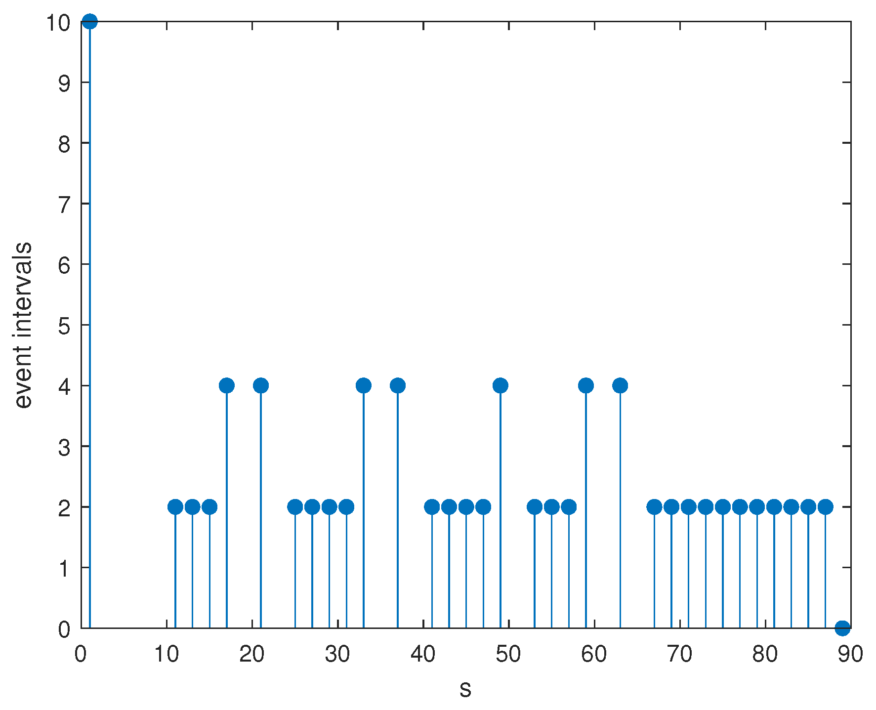
4. Numerical Example with Simulations

To illustrate the significance of the designed controller and the validity of the results, this section provides some numerical examples with simulation.
Example 1.
Considerthe drive DTRNNs (1) with n = 2 and the following parameters:
x 1 ( s + 1 ) = c 1 x 1 ( s ) + a 11 f 1 x 1 ( s ) + a 12 f 2 x 2 ( s ) + b 11 g 1 x 1 s d ( s ) + b 12 g 2 x 2 s d ( s ) + I 1 x 2 ( s + 1 ) = c 2 x 2 ( s ) + a 21 f 1 x 1 ( s ) + a 22 f 2 x 2 ( s ) + b 21 g 1 x 1 s d ( s ) + b 22 g 2 x 2 s d ( s ) + I 2
where c 1 = 0.8 , c 2 = 0.3 , a 11 = 1.05 , a 12 = 0.5 , a 21 = 2.9 , a 22 = 2 , b 11 = 1.7 , b 12 = 1.8 , b 21 = 0.3 , b 22 = 2.5 , The activation function f j x j = g j x j = 10 sin 0.03 x j tanh 0.02 x j , j = 1 , 2 . Givn d M = 4 , τ M = 2 , I 1 = I 2 = 0 , U 1 = 0.1 0 0 0.1 , U 2 = 0.5 0 0 0.5 . The response DTRNNs (2) are given as
y 1 ( s + 1 ) = c 1 y 1 ( s ) + a 11 f 1 y 1 ( s ) + a 12 f 2 y 2 ( s ) + b 11 g 1 y 1 s d ( s ) + b 12 g 2 y 2 s d ( s ) + I 1 + u 1 ( s ) y 2 ( s + 1 ) = c 2 y 2 ( s ) + a 21 f 1 y 1 ( s ) + a 22 f 2 y 2 ( s ) + b 21 g 1 y 1 s d ( s ) + b 22 g 2 y 2 s d ( s ) + I 2 + u 2 ( s ) .
If the state feedback control is not considered, the state trajectory simulation of the open-loop system is shown in Figure 2, and we find that the open drive-response DTRNNs (54) and (55) are unstable and asynchronous in Figure 3 and Figure 4. Therefore, we designed a state feedback controller with ETC. By the event-triggered mechanism (6), we assume δ = 0.2 . According to (50), the corresponding feasible solutions are obtained as
P = 10 14 0.3146 0.0535 0.0535 0.1547 , P ˜ = 113.0679 0.5640 0.5640 101.6117 , S 1 = 10 13 0.2767 0.0051 0.0051 0.3515 , S 2 = 10 13 0.4432 0.0080 0.0080 0.4822 , R 1 = 10 13 0.3359 0.0030 0.0030 0.3207 , R 2 = 10 13 0.3558 0.0061 0.0061 0.3289 , N 1 = 113.0679 0.5640 0.5640 101.6117 , N 2 = 113.0679 0.5640 0.5640 101.6117 ρ = 1.3682 × 10 12 , ϵ = 9.5478 × 10 13 , Ω = 10 12 0.2656 0.0054 0.0054 0.3413 , K ^ = 1.1169 0.4546 0.3552 1.6840 .
Figure 5 presents the simulation of the closed-loop system, and it is clear that the system is asymptotically stable. It can be seen from Figure 6 and Figure 7 that the drive-response DTRNNs (54) and (55) are synchronous, and Figure 8 shows the event interval with control gain K ^ and triggered matrix Ω .
Compared with the continuous case in the literature [25], the time required for the error system to stabilize in the discrete case will be longer, but the number of event triggers will be significantly less, so as to truly save network space, reduce network pressure, and save resources.
Example 2.
For systems (54) and (55), take the same parameters and activation function as in Example 1, consider the different frequency with 2 steps. From example 1, we know that the open driven-response DTRNNs (54) and (55) are not synchronized. From Theorem 2, the event-triggered weight matrix and controller gain can be designed as follows:
Ω = 10 12 0.2656 0.0054 0.0054 0.3413 , K ^ = 1.1169 0.4546 0.3552 1.6840 .
From Figure 9, we find that the error system is convergent to zero. It means that the driven DTRNNs and response DTRNNs are synchronized with 2 steps under controller (7), which also can be shown by Figure 10 and Figure 11. Figure 12 shows the event-triggered release interval. That is to say the designed controller is effective.

5. Conclusions

This article mainly analyzes the synchronization issue of time-varying delay DTRNNs based on ETC. By constructing a suitable LKF, a logical condition for the asymptotic stability of the error system was obtained by analysis, which ensures that the DTRNNs are synchronized. On this basis, an appropriate event-triggered state feedback controller was designed, and two numerical examples were used to verify that the designed controller is feasible. Based on recent research results, this paper provides a new criterion for the study of RNNs of discrete systems with time-varying delay. The set controller is more suitable for engineering applications and is more universal.

Author Contributions

Conceptualization, G.C.; Data curation, L.Y. and Z.W.; Formal analysis, F.J.; Investigation, G.C.; Methodology, L.Y., G.C. and F.J.; Project administration, Z.W.; Supervision, G.C.; Writing—original draft, L.Y. All authors have read and agreed to the published version of the manuscript.

Funding

This work was supported by the National Natural Science Foundation of China (Grant Nos. 61473213, 11701304), Natural Science Foundation of Ningbo Municipality (Grant Nos. 2019A610041, 2021J143) and Hubei Province Key Laboratory of System Science in Metallurgical Process (Wuhan University of Science and Technology) (Grant No. Z202102).

Institutional Review Board Statement

Not applicable.

Informed Consent Statement

Not applicable.

Conflicts of Interest

The authors declare no conflict of interest.

References

  1. Botmart, T.; Niamsup, P. Exponential synchronization of complex dynamical network with mixed time-varying and hybrid coupling delays via intermittent control. Adv. Differ. Equ. 2014, 2014, 1–33. [Google Scholar] [CrossRef] [Green Version]
  2. Vadivel, R.; Ali, M.S.; Joo, Y.H. Event-triggered H synchronization for switched discrete time delayed recurrent neural networks with actuator constraints and nonlinear perturbations. J. Frankl. Inst. 2020, 357, 4079–4108. [Google Scholar] [CrossRef]
  3. Chen, G.; Gao, Y.; Zhu, S. Finite-time dissipative control for stochastic interval systems with time-delay and Markovian switching. Appl. Math. Comput. 2017, 310, 169–181. [Google Scholar] [CrossRef]
  4. Wen, S.; Zeng, Z.; Huang, T.; Meng, Q.; Yao, W. Lag synchronization of switched neural networks via neural activation function and applications in image encryption. IEEE Trans. Neural Netw. Learn. Syst. 2015, 26, 1493–1502. [Google Scholar] [CrossRef] [Green Version]
  5. Niamsup, P.; Botmart, T.; Weera, W. Modified function projective synchronization of complex dynamical networks with mixed time-varying and asymmetric coupling delays via new hybrid pinning adaptive control. Adv. Differ. Equ. 2017, 2017, 1–31. [Google Scholar] [CrossRef] [Green Version]
  6. Botmart, T.; Yotha, N.; Niamsup, P.; Weera, W. Hybrid adaptive pinning control for function projective synchronization of delayed neural networks with mixed uncertain couplings. Complexity 2017, 2017, 4654020. [Google Scholar] [CrossRef] [Green Version]
  7. Ali, M.S.; Marudai, M. Stochastic stability of discrete-time uncertain recurrent neural networks with Markovian jumping and time-varying delays. Math. Comput. Model. 2011, 54, 1979–1988. [Google Scholar]
  8. Liu, X.G.; Wang, F.X.; Shu, Y.J. A novel summation inequality for stability analysis of discrete-time neural networks. J. Comput. Appl. Math. 2016, 304, 160–171. [Google Scholar] [CrossRef]
  9. Wei, F.; Chen, G.; Wang, W. Finite-time stabilization of memristor-based inertial neural networks with time-varying delays combined with interval matrix method. Knowl.-Based Syst. 2021, 230, 107395. [Google Scholar] [CrossRef]
  10. Wang, H.; Duan, S.; Huang, T.; Tan, J. Synchronization of memristive delayed neural networks via hybrid impulsive control. Neurocomputing 2017, 267, 615–623. [Google Scholar] [CrossRef]
  11. Wei, F.; Chen, G.; Wang, W. Finite-time synchronization of memristor neural networks via interval matrix method. Neural Netw. 2020, 127, 7–18. [Google Scholar] [CrossRef] [PubMed]
  12. Wang, G.; Shen, Y. Exponential synchronization of coupled memristive neural networks with time delays. Neural Comput. Appl. 2014, 24, 1421–1430. [Google Scholar] [CrossRef]
  13. Wang, S.; Cao, Y.; Wen, S.; Guo, Z.; Huang, T.; Chen, Y. Projective synchroniztion of neural networks via continuous/periodic event-based sampling algorithms. IEEE Trans. Netw. Sci. Eng. 2020, 7, 2746–2754. [Google Scholar] [CrossRef]
  14. Wang, J.L.; Qin, Z.; Wu, H.N.; Huang, T. Finite-Time Synchronization and H Synchronization of Multiweighted Complex Networks With Adaptive State Couplings. IEEE Trans. Cybern. 2018, 50, 600–612. [Google Scholar] [CrossRef]
  15. Han, J.; Chen, G.; Hu, J. New results on anti-synchronization in predefined-time for a class of fuzzy inertial neural networks with mixed time delays. Neurocomputing 2022, 495, 26–36. [Google Scholar] [CrossRef]
  16. Hoppensteadt, F.C.; Izhikevich, E.M. Pattern recognition via synchronization in phase-locked loop neural networks. IEEE Trans. Neural Netw. 2000, 11, 734–738. [Google Scholar] [CrossRef] [PubMed] [Green Version]
  17. Vassilieva, E.; Pinto, G.; de Barros, J.; Suppes, P. Learning pattern recognition through quasi-synchronization of phase oscillators. IEEE Trans. Neural Netw. 2010, 22, 84–95. [Google Scholar] [CrossRef] [PubMed]
  18. Liu, Y.; Wang, Z.; Liang, J.; Liu, X. Stability and synchronization of discrete-time Markovian jumping neural networks with mixed mode-dependent time delays. IEEE Trans. Neural Netw. 2009, 20, 1102–1116. [Google Scholar] [PubMed] [Green Version]
  19. Zhang, L.; Yi, Z.; Zhang, S.L.; Heng, P.A. Activity invariant sets and exponentially stable attractors of linear threshold discrete-time recurrent neural networks. IEEE Trans. Autom. Control. 2009, 54, 1341–1347. [Google Scholar] [CrossRef]
  20. Bao, H.; Park, J.H.; Cao, J. Adaptive synchronization of fractional-order memristor-based neural networks with time delay. Nonlinear Dyn. 2015, 82, 1343–1354. [Google Scholar] [CrossRef]
  21. Chandrasekar, A.; Rakkiyappan, R. Impulsive controller design for exponential synchronization of delayed stochastic memristor-based recurrent neural networks. Neurocomputing 2016, 173, 1348–1355. [Google Scholar] [CrossRef]
  22. Tabuada, P. Event-triggered real-time scheduling of stabilizing control tasks. IEEE Trans. Autom. Control. 2007, 52, 1680–1685. [Google Scholar] [CrossRef] [Green Version]
  23. Dong, Q.; Yu, P.; Ma, Y. Event-triggered synchronization control of complex networks with adaptive coupling strength. J. Frankl. Inst. 2022, 359, 1215–1234. [Google Scholar] [CrossRef]
  24. Suo, J.; Wang, Z.; Shen, B. Pinning synchronization control for a class of discrete-time switched stochastic complex networks under event-triggered mechanism. Nonlinear Anal. Hybrid Syst. 2020, 37, 100886. [Google Scholar] [CrossRef]
  25. Que, H.; Fang, M.; Wu, Z.G.; Su, H.; Huang, T.; Zhang, D. Exponential synchronization via aperiodic sampling of complex delayed networks. IEEE Trans. Syst. Man, Cybern. Syst. 2018, 49, 1399–1407. [Google Scholar] [CrossRef]
  26. Jin, L.; He, Y.; Wu, M. Improved delay-dependent stability analysis of discrete-time neural networks with time-varying delay. J. Frankl. Institute 2017, 354, 1922–1936. [Google Scholar] [CrossRef]
  27. Ding, S.; Wang, Z. Event-triggered synchronization of discrete-time neural networks: A switching approach. Neural Netw. 2020, 125, 31–40. [Google Scholar] [CrossRef]
  28. Wen, S.; Zeng, Z.; Chen, M.Z.; Huang, T. Synchronization of switched neural networks with communication delays via the event-triggered control. IEEE Trans. Neural Netw. Learn. Syst. 2016, 28, 2334–2343. [Google Scholar] [CrossRef] [PubMed]
  29. Kan, X.; Wang, Z.; Shu, H. State estimation for discrete-time delayed neural networks with fractional uncertainties and sensor saturations. Neurocomputing 2013, 117, 64–71. [Google Scholar] [CrossRef]
  30. Wu, Z.; Su, H.; Chu, J.; Zhou, W. Improved delay-dependent stability condition of discrete recurrent neural networks with time-varying delays. IEEE Trans. Neural Netw. 2010, 21, 692–697. [Google Scholar] [PubMed]
  31. Wang, H.; Shi, P.; Lim, C.C.; Xue, Q. Event-triggered control for networked Markovian jump systems. Int. J. Robust Nonlinear Control. 2015, 25, 3422–3438. [Google Scholar] [CrossRef]
  32. Xiong, J.; Lam, J. Stabilization of networked control systems with a logic ZOH. IEEE Trans. Autom. Control. 2009, 54, 358–363. [Google Scholar] [CrossRef] [Green Version]
Figure 1. Synchronization flow chart for DTRNNs.
Mathematics 10 02816 g001
Figure 2. Trajectory curve of an error system e ( s ) without controller.
Mathematics 10 02816 g002
Figure 3. Trajectory curves of x 1 s and y 1 s without controller.
Mathematics 10 02816 g003
Figure 4. Trajectory curves of x 2 s and y 2 s without controller.
Mathematics 10 02816 g004
Figure 5. Trajectory curve of an error system e ( s ) with controller.
Mathematics 10 02816 g005
Figure 6. Trajectory curves of x 1 s and y 1 s with controller.
Mathematics 10 02816 g006
Figure 7. Trajectory curves of x 2 s and y 2 s with controller.
Mathematics 10 02816 g007
Figure 8. Release intervals with K ^ and Ω .
Mathematics 10 02816 g008
Figure 9. Trajectory curves of x 1 s and y 1 s with controller.
Mathematics 10 02816 g009
Figure 10. Trajectory curves of x 2 s and y 2 s with controller.
Mathematics 10 02816 g010
Figure 11. Trajectory curve of an error system e ( s ) with controller.
Mathematics 10 02816 g011
Figure 12. Release intervals with K ^ and Ω .
Mathematics 10 02816 g012
Publisher’s Note: MDPI stays neutral with regard to jurisdictional claims in published maps and institutional affiliations.

