Article

Study on Dynamic Characteristics of a Rotating Sandwich Porous Pre-Twist Blade with a Setting Angle Reinforced by Graphene Nanoplatelets

1
Key Laboratory of Structural Dynamics of Liaoning Province, School of Sciences, Northeastern University, Shenyang 110819, China
2
Department of General Education, Shenyang Sport University, Shenyang 110115, China
*
Authors to whom correspondence should be addressed.
Mathematics 2022, 10(15), 2814; https://doi.org/10.3390/math10152814
Submission received: 26 April 2022 / Revised: 26 July 2022 / Accepted: 29 July 2022 / Published: 8 August 2022
(This article belongs to the Special Issue Applied Computing and Artificial Intelligence)

Abstract

:
Lightweight blades with high strength are urgently needed in practical rotor engineering. Sandwich structures with porous core and reinforced surfaces are commonly applied to achieve these mechanical performances. Moreover, blades with large aspect ratios are established by the elastic plate models in theory. This paper studies the vibration of a rotating sandwich pre-twist plate with a setting angle reinforced by graphene nanoplatelets (GPLs). Its core is made of foam metal, and GPLs are added into the surface layers. Supposing that nanofillers are perfectly connected with matrix material, the effective mechanical parameters of the surface layers are calculated by the mixing law and the Halpin–Tsai model, while those of the core layers are determined by the open-cell scheme. The governing equation of the rotating plate is derived by employing the Hamilton principle. By comparing with the finite element method obtained by ANSYS, the present model and vibration analysis are verified. The material and structural parameters of the blade, including graphene nanoplatelet (GPL) weight faction, GPL distribution pattern, porosity coefficient, porosity distribution pattern, length-to-thickness ratio, length-to-width ratio, setting angle and pre-twist angle of the plate are discussed in detail. The finds provide important inspiration in the designing of a rotating sandwich blade.

1. Introduction

Blade structures are commonly applied in several rotating machineries, such as aero engines and wind turbines. As the mechanical performance of the rotor structure is required to improve, the blade structure is designed to be lighter and thinner. Blades are extremely susceptible to vibration damage, which accounts for a very large proportion of the failure of the blade. So, it is very meaningful to study vibration behaviors of blades. In previous studies, blades are often simplified as rotating plates or rotating beams, which have been studied comprehensively [1,2,3,4,5,6,7,8,9,10]. Based on Chebyshev polynomials, Gen et al. [11] studied the nonlinear dynamic behavior of blades with variable rotating speed. By using the Galerkin method, Avramov et al. [12] investigated the bending-torsional nonlinear vibration behavior of a rotating beam with asymmetric cross-section. By adopting the Ritz method, Mcgee [13] calculated natural frequencies of cantilever parallelepipeds that were skewed and twisted in the meantime. Yao et al. [14] studied the nonlinear dynamic behavior of high-speed rotating plates. Based on the Hamilton principle, Xu et al. [15] studied the nonlinear vibration of a rotating cantilever beam in the magnetic field. Wang et al. [16] studied the nonlinear stability of rotating blades. Hashemia et al. [17] presented the finite element formulas for vibration analysis of rotating thick plates. Li et al. [18] studied the free vibration of variable rotating cantilever rectangular functionally graded (FG) plates moving in a wide range. By using the Donner shell theory, Shakour [19] studied vibrations of a rotating FG conical shell in different thermal environment. Based on the Hamilton principle, Qin et al. [20] investigated the bent-bending coupled vibration of rotating composite thin-walled beams under aerodynamic and humid conditions. Yutaek et al. [21] proposed a dynamic model of rotating pre-torsional blades with variable cross-section. Yang et al. [22] promoted the FG plate theory proposed by Mian and Spencer from two aspects. Arumugam et al. [23] studied vibration behaviors of a planar layered laminate with rotational effects. Tuzzi et al. [24] conducted a study of coupling vibrations between shaft-bending and disk-zero nodal diameter mode vibration in a flexible shaft–disk assembly. Based on classical plate theory and Hamilton principle, Sun et al. [25] investigated the vibration characteristics of rotating blades with a staggered angle.
Due to the influence of aerodynamic loads on the blade during rotation, higher requirements are put forward for the structural strength of the blade. The traditional blade material has not met the needs. GPLs have been very popular as a reinforced material in the past few years and widely used in various engineering fields, such as physics, electrical engineering, materials science and nanoengineering applications [26,27,28,29,30]. Its structural stiffness and lightweight meet the requirements, which has become the focus of scholars’ research. Zhao et al. [31] studied the free vibration of GPL reinforced rotating FG pre-twisted blade-shaft assembly. Li et al. [32] carried out nonlinear vibration and dynamic buckling analysis of laminated FG porous plates reinforced by GPLs. Yang et al. [33] studied the buckling and free vibration behavior of FG porous nanocomposite plates reinforced with GPLs. Based on the Timoshenko beam theory, Chen et al. [34] analyzed the elastic buckling and static bending of shear deformable FG porous beams. Wu et al. [35] studied the parameter instability of FG-GPL reinforced nanocomposite plate under the action of periodic uniaxial plane internal force in uniform temperature field. Lei et al. [36] used element-free -Ritz method to conduct free vibration analysis on single-walled carbon nanotube reinforced FG nanocomposite plate. Yang et al. [37] studied the buckling and post-buckling behavior of FG multilayer nanocomposite beams reinforced by low content GPLs on elastic foundation. Wang et al. [38] studied the eigenvalue buckling of multilayer FG cylindrical shells reinforced with GPLs by using finite element method.
To sum up, GPL reinforced porous rotor structures are suitable for high-speed rotating blades to achieve high strength or light weight. Moreover, the sandwich blade structure with GPL reinforced surfaces and porous core could be designed to avoid air turbulence. This paper investigated the theoretical modeling and free vibration of a pre-twist sandwich blade. To the authors′ knowledge, almost no study focused on the vibration analysis of a rotating sandwich blade with GPL reinforced porous core. Based on the Kirchhoff plate theory, the rotating pre-twist blade with a setting angle is established in this paper. The equations of motion are derived by applying the Hamilton principle and then solved by the using the hypothetical modal method. The effects of material and structural parameters of the sandwich blade on its free vibration are examined in detail. The findings shed a bright light on the design of sandwich blades with GPL reinforced porous core to achieve better mechanical performance.

2. Theoretical Model

Figure 1 shows a rotating pre-twist blade with a setting angle, which attached to a rigid body. To describe the motion and displacements of the blade, three coordinate systems are carried out. The O-XYZ coordinate system is established on the rigid body, while the reference coordinate system o-xyz is fixed on the blade root. Moreover, another reference coordinate system o-uvw is fixed on the blade at a distance x away from the point o. The radius of the rigid body is Rd, and it rotates around the Y axis at a constant speed Ω. The length, width and thickness of the blade are a, b and h, respectively. Moreover, hc and hf are the thicknesses of the porous core and the GPL reinforced face layer, respectively. It can be known that h = hc + 2 hf. Then, define m = hc/hf, which is the ratio of the core to the surface layer. The setting angle and pre-twist angle of the blade are θ and φ, respectively. The twist angle at an arbitrary point on the blade is β ( x ) = θ + k x , where k = ( φ θ ) / a .

3. Material Properties

As shown in Figure 2, three different porosity distribution patterns are considered in this paper. Plus, it can be seen clearly that the material parameters vary along the blade thickness direction. Pattern X means that more pores are distributed around the edges; Pattern O tells more pores are distributed in the middle surface; Pattern U gives the uniform porosity distribution. Based on the open-cell scheme [39], the material properties are
Pattern   X :   E ( Z ) = E 1 1 e 0 cos ( π Z / h ) ν ( Z ) = ν 1 1 e 0 cos ( π Z / h ) ρ ( Z ) = ρ 1 1 e m cos ( π Z / h ) Pattern   U :   E ( Z ) = E 1 α ν ( Z ) = ν 1 α ρ ( Z ) = ρ 1 α Pattern   O :   E ( Z ) = E 1 1 e 0 ( 1 cos ( π Z / h ) ) ν ( Z ) = ν 1 1 e 0 ( 1 cos ( π Z / h ) ) ρ ( Z ) = ρ 1 1 e m ( 1 cos ( π Z / h ) )
where E ( Z ) , ρ ( Z ) , ν ( Z ) are the effective elasticity modulus, mass density, Poisson’s ratio of the core layer, respectively. E 1 , ρ 1 , ν 1 are the corresponding material parameters of core layer without pores. e 0 , α , e 0 are the porosity coefficients of the three distribution patterns. e m , α , e m are the mass density coefficients of the three distribution patterns.
The relationship between porosity coefficients and mass density coefficients can be given by
1 e m cos ( π Z / h ) = 1 e 0 cos ( π Z / h ) α = α 1 e m 1 cos ( π Z / h ) = 1 e 0 1 cos ( π Z / h )
Table 1 shows the relationship of porosity coefficients of the three patterns.
GPLs are added to the surface layers. Due to high precision, the Halpin–Tsai model [40,41] is used to calculate the surface layers’ effective elasticity modulus. The formula is shown as
E S = E M 3 8 1 + ξ L η L V G P L 1 η L V G P L + 5 8 1 + ξ T η T V G P L 1 η T V G P L
where η T and η L are given by
η L = E G P L E M E G P L + ξ L E M η T = E G P L E M E G P L + ξ T E M
and ξ T and ξ L can be expressed as
ξ L = 2 L G P L / t G P L ξ T = 2 w G P L / t G P L
where E M and E G P L are the elasticity modulus of the matrix and GPLs. L G P L , w G P L and t G P L are the length, width and thickness of GPLs.
Based on the mixing rule, the mass density and Poisson’s ratio are
ρ s = V G P L ρ G P L + ( 1 V G P L ) ρ M υ s = V G P L υ G P L + ( 1 V G P L ) υ M
where υ G P L and υ m are the Poisson’s ratio of matrix and GPLs, respectively. ρ G P L and ρ m are the mass density of matrix material GPLs, respectively. V G P L is the volume fraction of GPLs in the plate, expressed as
V G P L = W G P L W G P L + ρ G P L 1 W G P L / ρ M
where, W G P L is the weight fraction of GPLs, obtained as
W G P L = 4 Z 2 h f 2 λ 1 W 0                                                                   Pattern X p λ 2 W 0                                                                                 Pattern U p 1 4 Z 2 h f 2 λ 3 W 0                                         Pattern O p
where W0 is the GPL characteristic value; λ 1 , λ 2 , λ 3 are the GPL weight fraction indices determined by the GPL weight distribution patterns, as listed in Table 2.
The corresponding GPL distribution patterns are as shown in Figure 3.

4. Equations of Motion

To describe the motion of the rotating plate, three coordinate systems are established. The coordinates of an arbitrary point on the plate in the local coordinate system are R = ( x + R d ) i + y j + ( z + w ) k .
Then, the coordinate of the same point on the plate in the fixed coordinate system is
R = 1 0 0 0 cos β ( x ) sin β ( x ) 0 sin β ( x ) cos β ( x ) x + R d y z + w
The speed of the plate is V = R ˙ + ( Ω i × R ) , where Ω is the rotating speed.
Then, the kinetic energy of the rotating blade can be obtained as
T P = 1 2 ρ h 0 b 0 a w 2 Ω 2 + w t 2 + ( R + x ) 2 2 w ( cos β ( x ) ) w t ( R + x ) Ω + y 2 d x d y
Considering the gyroscopic effect, the rotating strain potential energy is
U 1 = E h 3 24 1 υ 2 0 b 0 a 1 B 4 2 w x 2 + 2 w y 2 2 2 1 υ B 2 2 w x 2 2 w y 2 2 w x y 2 d x d y
where f c 1 and f c 2 are the centrifugal forces in two directions of the blade, expressed as
f c 1 = ρ h Ω 2 x a ( R + x ) d x
f c 2 = ρ h Ω 2 y b 2 y ( sin ( β ( x ) ) 2 ) d y
The total potential energy can be given by
U P = E h 3 24 1 υ 2 0 b 0 a 1 B 4 2 w x 2 + 2 w y 2 2 2 1 υ B 2 2 w x 2 2 w y 2 2 w x y 2 d x d y + 1 2 ρ h Ω 2 0 b 0 a R ( a x ) + 1 2 a 2 x 2 w x 2 + ( b 2 y 2 ) ( sin ( β ( x ) ) ) 2 d x d y
Applying the Hamiltonian variational principle δ t 0 t 1 T P U P d t = 0 , the equations of motion can be derived as
0 b 0 a ρ h ω 2 + Ω 2 W δ W 1 2 ρ h Ω 2 R ( a x ) + 1 2 a 2 x 2 W x δ W x + ( b 2 4 y 2 ) ( sin β ( x ) ) 2 W y δ W y D B 4 2 W x 2 δ 2 W x 2 + 2 W y 2 δ 2 W y 2 + 2 W x 2 δ 2 W y 2 + 2 W y 2 δ 2 W x 2 + D 1 υ B 2 2 W x 2 δ 2 W y 2 + 2 W y 2 δ 2 W x 2 2 2 W x y δ 2 W x y d x d y = 0
According to the approximation method of combined series of beam function, the vibration mode expression, satisfying all displacement boundary conditions, is
W x , y = m = 1 M n = 1 N A m n ϕ m x φ n y
The fixed-free beam function ϕ m x and the free-free beam function φ n y are given by
ϕ m x = cosh ( α m x ) cos α m x c m sinh ( α m x ) sin α m x φ n y = cosh ( β n y ) + cos β n y d n sinh ( β n y ) + sin β n y c m = cos α m a + cosh α m a sin α m a + sinh α m a , d n = cos β n b cosh β n b sin β n b sinh β n b cosh α m a cos α m a + 1 = 0 , cosh β n b cos β n b 1 = 0
By substituting the Equation (16) into Equation (15) and making the variational coefficient δ A m n zero, the frequency equation can be obtained as
0 b 0 a ρ h ω 2 + Ω 2 m = 1 M n = 1 N A m n φ m x φ n y ϕ i x φ j y D B 4 m = 1 M n = 1 N A m n φ m x φ n y φ i x φ j y + m = 1 M n = 1 N A m n φ m x φ n y φ i x φ j y + m = 1 M n = 1 N A m n φ m x φ n y φ i x φ j y + m = 1 M n = 1 N A m n φ m x φ n y φ i x φ j y + D ( 1 v ) B 2 m = 1 M n = 1 N A m n φ m x φ n y φ i x φ j y + m = 1 M n = 1 N A m n φ m x φ n y φ i x φ j y 2 m = 1 M n = 1 N A m n φ m x φ n y φ i x φ j y 1 2 ρ h Ω 2 R ( a x ) + 1 2 a 2 x 2 m = 1 M n = 1 N A m n φ m x φ n y φ i x φ j y 1 2 ρ h Ω 2 b 2 4 y 2 ( sin β ( x ) ) 2 m = 1 M n = 1 N A m n φ m x φ n y φ i x φ j y d x d y = 0
where, ω is the natural frequency of the plate.

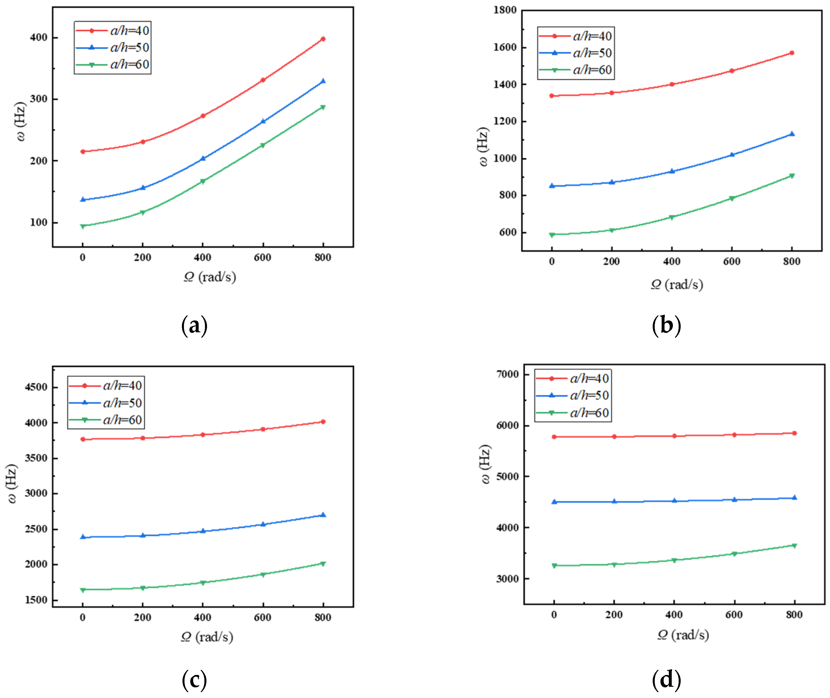
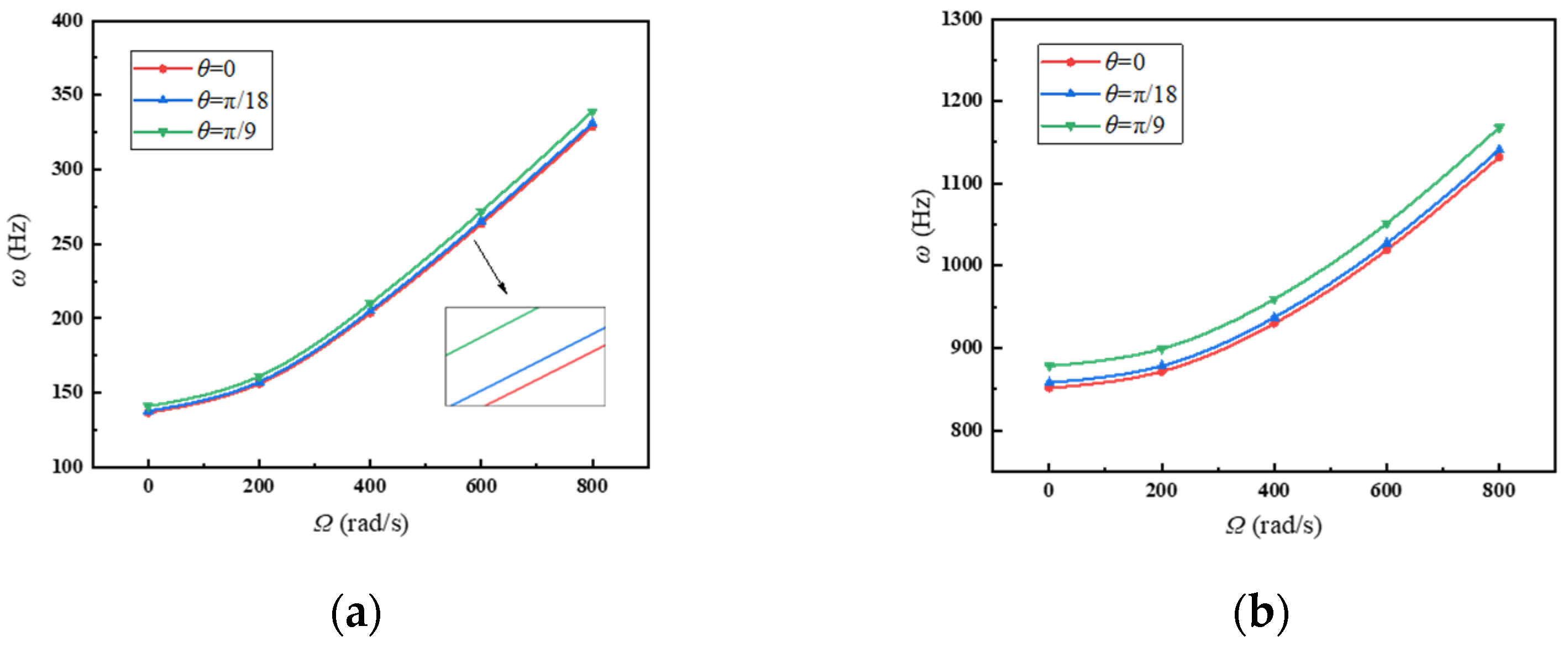
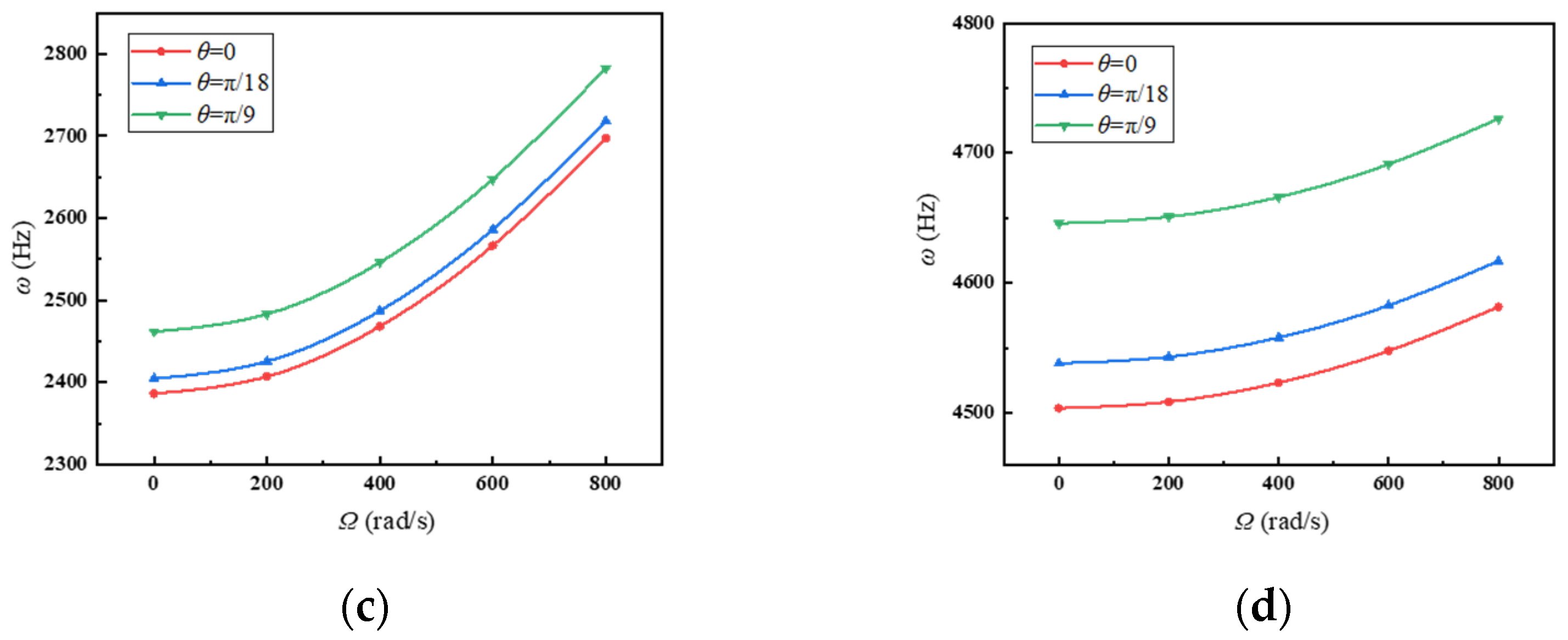
5. Results and Discussions

Before discussing the parameters, we need to conduct convergence analysis to verify correctness of theoretical solution. The structural and material parameters are shown as Table 3.
Table 4 shows variations of the first four frequencies with different mode numbers. It is seen that the mode number tends to be convergent at M = N = 15, which will be adopted in the following discussion.
The comparison between theoretical results and finite element results obtained from ANSYS of the first four-order frequencies and corresponding vibration modes is depicted in Figure 3 and Table 4, the Solid 186 element in ANSYS is applied. Plus, the numbers of elements and nodes are 11,616 and 23,735, respectively. The convergence analysis for the element number is conducted as given in Figure 4 and Table 5. It can be clearly seen from Figure 5 and Table 6 that the error is less than 2%, and the vibration modes are in good agreement, which indicates that the present model and analysis are correct.
The idea of controlling variable method is adopted for the argument discussion in this article. The parameters are demonstrated in the Table 7. Moreover, the GPL distribution and pore distribution are Pattern X, and the porosity coefficient e0 = 0.1, if not specified.
Figure 6 shows variations of the first four frequencies with the rotating plate in the case of different GPL weight fraction. The frequencies of the plate gradually increase as the rotating speed rises. Moreover, it can be clearly seen that adding more GPLs into the matrix leads to the higher frequencies. Therefore, we can add more GPLs in a small amounts to the surface layers of the plate to improve its mechanical performance.
Figure 7 depicts variations of the first four frequencies with the rotating plate in the case of different porosity coefficients. Obviously, the frequencies of the plate are decreased with larger porosity coefficients, which means that the core layer has more pores. It can significantly reduce the weight, and the impact on the vibration frequency of the plate is relatively small. So, it is necessary to choose the porous core to achieve weight reduction.
Variations of the first four frequencies with the rotating plate in the case of different ratios of surface-thickness and core-thickness are exhibited in Figure 8. As the ratios continue to increase, frequencies of the plate increase significantly. It tells those thicker surfaces give a hand in enhancing the structural stiffness.
Figure 9 displays variations of the first four frequencies with the rotating plate in the case of different GPL distribution patterns. The plate with GPL distribution pattern X has the highest natural frequencies. To obtain better mechanical performance, adding more GPLs around the surfaces is a good choice.
Figure 10 shows variations of the first four frequencies with the rotating plate in the case of different porosity distribution patterns. It is obvious that porosity distribution pattern X provides the greater frequencies than the other two porosity distribution patterns. One can tell that setting more pores around the edges and arranging larger pores in the middle plane are conducive to achieve better structural stiffness.
Variations of the first four frequencies with the rotating plate in the case of length-to-thickness ratio of the plate are given in Figure 11, where the blade length is constant. Lower length-to-thickness ratio of the plate shows greater frequencies. It indicates that thinner blades should be designed in rotating machines for better mechanical performance.
Figure 12 plots variations of the first four frequencies with the rotating plate in the case of different length-to-width ratio of the plate, where the blade width is constant. One can see that frequencies decrease dramatically with increase of the length-to-width ratio of the plate. It can be told that the blade length should be closer to the blade width to enhance the structural performance of the plate.
Figure 13 depicts variations of the first four frequencies with the rotating plate in the case of different pre-twist angles. Increasing the pre-twist angle of the plate tends to reduce the frequencies. It should be noted that the blade should be flatter in the absence of additional requirements.
Figure 14 shows variations of the first four frequencies with the rotating plate in the case of different setting angles. Visibly, raising the setting angle will increase the frequencies of the plate. We can know that the blade with larger setting angle contributes to improve the structural performance.

6. Conclusions

This paper studies free vibration analysis of a rotating sandwich porous blade reinforced with GPLs. The effective material parameters of the sandwich plate are obtained by the mixing law and the Halpin–Tsai model. In addition, the frequencies can be calculated based on the Hamilton principle and the method of hypothesis modes. Plus, the present results are verified by the finite element method. Some useful conclusions have been drawn as follows:
(1)
Better mechanical performance can be achieved by adding more GPLs into the surface layer in a small content and making more GPLs on the edges of the plate.
(2)
Setting less pores in the core layer and arranging more smaller pores around edges can enhance the structural stiffness.
(3)
Applying thinner core layer contributes to better structural stiffness of the sandwich structure.
(4)
Shorter and thinner blade should be designed to obtain better mechanical properties.
(5)
Appropriately increasing setting angle and reducing pre-twist angle can is a good choice to obtain better structural stiffness.

Author Contributions

Conceptualization, J.P. and T.Z.; Funding acquisition, L.Z. and T.Z.; Investigation, J.P., L.Z. and T.Z.; Methodology, J.P. and L.Z.; Supervision, T.Z.; Writing—original draft, J.P.; Writing—review & editing, T.Z. All authors have read and agreed to the published version of the manuscript.

Funding

This research was funded by the Major Project of Aeroengine and Gas Turbine of China (HT-J2019-IV-0016-0084), the National Natural Science Foundation of China (No. 51805076, No. U1708255 and No. 52005086), the National Science and Technology Major Project of China (J2019-I-0008-0008) and the Fundamental Research Funds for the Central Universities of China (N2105013).

Conflicts of Interest

The authors declare no conflict of interest in preparing this article.

References

  1. Mohammad, R.P.; Amir, R.M. Hygro-thermo-elstic nonlinear analysis of functionally gaded porous composite thin and moderately thick shallow panels. Mech. Adv. Mater. Struct. 2022, 29, 594–612. [Google Scholar]
  2. Zhao, T.Y.; Ma, Y.; Zhang, H.Y.; Pan, H.G.; Cai, Y. Free vibration analysis of a rotating graphene nanoplatelet reinforced pre-twist blade-disk assembly with a setting angle. Appl. Math. Model. 2021, 93, 578–596. [Google Scholar] [CrossRef]
  3. Zhao, T.Y.; Yan, K.; Li, H.W.; Wang, X. Study on theoretical modeling and vibration performance of an assembled cylindrical shell-plate structure with whirl motion. Appl. Math. Model. 2022, 110, 618–632. [Google Scholar] [CrossRef]
  4. Zhao, T.Y.; Cui, Y.S.; Pan, H.G.; Yuan, H.Q.; Yang, J. Free vibration analysis of a functionally graded graphene nanoplatelet reinforced disk-shaft assembly with whirl motion. Int. J. Mech. Sci. 2021, 197, 106335. [Google Scholar] [CrossRef]
  5. Zhao, T.Y.; Cui, Y.S.; Wang, Y.Q.; Pan, H.G. Vibration characteristics of graphene nanoplatelet reinforced disk-shaft rotor with eccentric mass. Mech. Adv. Mater. Struct. 2021. [Google Scholar] [CrossRef]
  6. Zhao, T.Y.; Li, K.; Ma, H. Study on dynamic characteristics of a rotating cylindrical shell with uncertain parameters. Anal. Math. Phys. 2022, 12, 97. [Google Scholar] [CrossRef]
  7. Zhao, T.Y.; Wang, Y.X.; Pan, H.G.; Yuan, H.Q.; Cai, Y. Nonlinear forced vibration analysis of spinning shaft-disk assemblies under sliding bearing supports. Math. Methods Appl. Sci. 2021, 44, 12283–12301. [Google Scholar] [CrossRef]
  8. Zhang, W.; Li, X.; Ma, H.; Luo, Z.; Li, X. Transfer learning using deep representation regularization in remaining useful life prediction across operating conditions. Reliab. Eng. Syst. Saf. 2021, 211, 107556. [Google Scholar] [CrossRef]
  9. Xu, H.; Wang, Y.Q.; Zhang, Y.F. Free vibration of functionally graded graphene platelet-reinforced porous beams with spinning movement via differential transformation method. Arch. Appl. Mech. 2021, 12, 4817–4834. [Google Scholar] [CrossRef]
  10. Wang, Y.Q.; Zu, J.W. Vibration behaviors of functionally graded rectangular plates with porosities and moving in thermal environment. Aerosp. Sci. Technol. 2017, 69, 550–562. [Google Scholar] [CrossRef]
  11. Liu, G.; Chen, G.F.; Cui, F.S. Nonlinear vibration analysis of composite blade with variable rotating speed using Chebyshev polynomials. Eur. J. Mech. 2020, 82, 103976. [Google Scholar] [CrossRef]
  12. Avramov, K.V.; Pierre, C. Flexural-flexural-torsional Nonlinear Vibrations of Pre-twisted Rotating Beams with Asymmetric Cross-sections. J. Vib. Control 2007, 13, 329–364. [Google Scholar] [CrossRef]
  13. Mcgee, O.G. On the three-dimensional vibration analysis of simultaneously skewed and twisted cantilevered parallelepipeds. Int. J. Numer. Methods Eng. 1992, 33, 1388–1411. [Google Scholar] [CrossRef]
  14. Yao, M.H.; Ma, L.; Zhang, W. Nonlinear dynamics of the high-speed rotating plate. Int. J. Aerosp. Eng. 2018, 2018, 56109151. [Google Scholar] [CrossRef] [Green Version]
  15. Xu, X.P.; Han, Q.K.; Chu, F.L. Nonlinear vibration of a rotating cantilever beam in a surrounding magnetic field. Int. J. Non-Linear Mech. 2017, 95, 59–72. [Google Scholar] [CrossRef]
  16. Wang, F.X.; Zhang, W. Stability analysis of a nonlinear rotating blade with torsional vibrations. J. Sound Vib. 2012, 331, 5755–5773. [Google Scholar] [CrossRef]
  17. Hashemi, S.H.; Farhadi, S.; Carra, S. Free vibration analysis of rotating thick plates. J. Sound Vib. 2009, 323, 366–384. [Google Scholar] [CrossRef]
  18. Li, L.; Zhang, D.G. Free vibration analysis of rotating functionally graded rectangular plates. Compos. Struct. 2016, 136, 493–504. [Google Scholar] [CrossRef]
  19. Shakour, M. Free vibration analysis of functionally graded rotating conical shells in thermal environment. Compos. Part B 2019, 163, 574–584. [Google Scholar] [CrossRef]
  20. Qin, Y.; Wang, L.; Li, Y.H. Coupled vibration characteristics of a rotating composite thin-walled beam subjected to aerodynamic force in hygrothermal environment. Int. J. Mech. Sci. 2018, 140, 260–270. [Google Scholar] [CrossRef]
  21. Oh, Y.; Yoo, Y.H. Vibration analysis of a rotating pre-twisted blade considering the coupling effects of stretching, bending, and torsion. J. Sound Vib. 2018, 431, 20–39. [Google Scholar] [CrossRef]
  22. Yang, B.; Ding, H.J. Elasticity solutions for a uniformly loaded rectangular plate of functionally graded materials with two opposite edges simply supported. Acta Mech. 2009, 207, 245258. [Google Scholar] [CrossRef]
  23. Arumugam, A.B.; Rajamohan, V. Vibration analysis of rotating delaminated non-uniform composite plates. Aerosp. Sci. Technol. 2017, 60, 172–182. [Google Scholar]
  24. Tuzzi, G.; Schwingshackl, C.W. Study of coupling between shaft bending and disc zero nodal diameter modes in a flexible shaft-disc assembly. J. Sound Vib. 2020, 479, 115362. [Google Scholar] [CrossRef]
  25. Sun, J.; Kari, L.; Arteaga, I.L. A dynamic rotating blade model at an arbitrary stagger angle based on classical plate theory and the Hamilton’s principle. J. Sound Vib. 2013, 332, 1355–1371. [Google Scholar] [CrossRef]
  26. Bellucci, S.; Balasubramanian, C.; Micciulla, F. CNT composites for aerospace applications. J. Exp. Nanosci. 2007, 2, 193–206. [Google Scholar] [CrossRef]
  27. Gauvin, F.; Robert, M. Durability study of vinylester/silicate nanocomposites for civil engineering applications. Polym. Degrad. Stab. 2015, 121, 359–368. [Google Scholar] [CrossRef]
  28. Shi, G.; Araby, S.; Gibson, C.T. Graphene platelets and their polymer composites: Fabrication, structure, properties, and applications. Adv. Funct. Mater. 2018, 28, 1706705. [Google Scholar] [CrossRef]
  29. Zhao, T.Y.; Wang, Y.X. Analytical solution for vibration characteristics of rotating graphene nanoplatelet-reinforced plates under rub-impact and thermal shock. Adv. Compos. Lett. 2020, 29, 1–15. [Google Scholar] [CrossRef]
  30. Zhao, T.Y.; Jiang, L.P. Coupled free vibration of a functionally graded pre-twisted blade-shaft system reinforced with graphene nanoplatelets. Compos. Struct. 2021, 262, 113362. [Google Scholar] [CrossRef]
  31. Zhao, T.Y.; Yang, Y.F. Free vibration analysis of a spinning porous nanocomposite blade reinforced with graphene nanoplatelets. J. Strain Anal. 2021, 56, 574–586. [Google Scholar] [CrossRef]
  32. Li, Q.Y.; Wu, D. Nonlinear vibration and dynamic buckling analyses of sandwich functionally graded porous plate with graphene platelet reinforcement resting on Winkler–Pasternak elastic foundation. Int. J. Mech. Sci. 2018, 148, 596–610. [Google Scholar] [CrossRef]
  33. Yang, J.; Chen, D. Buckling and free vibration analyses of functionally graded graphene reinforced porous nanocomposite plates based on Chebyshev-Ritz method. Compos. Struct. 2018, 193, 281294. [Google Scholar] [CrossRef]
  34. Chen, D.; Yang, J. Elastic buckling and static bending of shear deformable functionally graded porous beam. Compos. Struct. 2015, 133, 54–61. [Google Scholar] [CrossRef] [Green Version]
  35. Wu, H.L.; Yang, J. Parametric instability of thermo-mechanically loaded functionally graded graphene reinforced nanocomposite plates. Int. J. Mech. Sci. 2018, 135, 431–440. [Google Scholar] [CrossRef] [Green Version]
  36. Lei, Z.; Liew, K. Free vibration analysis of functionally graded carbon nanotube-reinforced composite plates using the element-free kp-Ritz method inthermal environment. Compos. Struct. 2016, 106, 128–138. [Google Scholar] [CrossRef]
  37. Yang, J.; Wu, H.L. Buckling and postbuckling of functionally graded multilayer graphene platelet-reinforced composite beams. Compos. Struct. 2017, 161, 111–118. [Google Scholar] [CrossRef] [Green Version]
  38. Wang, Y.; Feng, C.; Zhao, Z.; Yang, J. Eigenvalue buckling of functionally graded cylindrical shells reinforced with graphene platelets (GPL). Compos. Struct. 2018, 202, 38–46. [Google Scholar] [CrossRef]
  39. Zhao, T.Y.; Jiang, L.P.; Yu, Y.X.; Wang, Y.Q. Study on theoretical modeling and mechanical performance of a spinning porous graphene nanoplatelet reinforced beam attached with double blades. Mech. Adv. Mater. Struct. 2022. [Google Scholar] [CrossRef]
  40. Yang, B.; Kitipornchai, S.; Yang, Y.F. 3D thermo-mechanical bending solution of functionally graded graphene reinforced circular and annular plates. Appl. Math. Model. 2017, 49, 69–86. [Google Scholar] [CrossRef] [Green Version]
  41. Ye, C.; Wang, Y.Q. Nonlinear forced vibration of functionally graded graphene platelet-reinforced metal foam cylindrical shells: Internal resonances. Nonlinear Dyn. 2021, 3, 2051–2069. [Google Scholar] [CrossRef]
Figure 1. A rotating pre-twist blade with a setting angle attached to a rigid body.
Mathematics 10 02814 g001
Figure 2. Porosity distribution patterns of the core layer: (a) Pattern XP; (b) Pattern UP; (c) Pattern OP.
Mathematics 10 02814 g002
Figure 3. GPL distribution patterns in the surface layer of the plate: (a) Pattern XG; (b) Pattern UG; (c) Pattern OG.
Mathematics 10 02814 g003
Figure 4. Finite element grid diagram. (a) Ne = 2868; (b) Ne = 4092; (c) Ne = 6523; (d) Ne = 11,616.
Mathematics 10 02814 g004
Figure 5. Comparison of the first-four vibration modes between theoretical and finite element results: (a,b) are the first vibration mode; (c,d) are the second vibration mode; (e,f) are the third vibration mode; (g,h) are the fourth vibration mode.
Mathematics 10 02814 g005
Figure 6. Variations of frequencies with rotating speed under different GPL weight fractions. (a) First frequency; (b) second frequency; (c) third frequency; (d) fourth frequency.
Mathematics 10 02814 g006
Figure 7. Variations of frequencies with rotating speed under different porosity coefficients. (a) First frequency; (b) second frequency; (c) third frequency; (d) fourth frequency.
Mathematics 10 02814 g007
Figure 8. Variations of frequencies with rotating speed under different ratios of core layer thickness and surface layer thickness. (a) First frequency; (b) second frequency; (c) third frequency; (d) fourth frequency.
Mathematics 10 02814 g008
Figure 9. Variations of frequencies with rotating speed under different GPL distribution patterns. (a) First frequency; (b) second frequency; (c) third frequency; (d) fourth frequency.
Mathematics 10 02814 g009aMathematics 10 02814 g009b
Figure 10. Variations of frequencies with rotating speed under different porosity distribution patterns. (a) First frequency; (b) second frequency; (c) third frequency; (d) fourth frequency.
Mathematics 10 02814 g010
Figure 11. Variations of frequencies with rotating speed under different length-to-thickness ratio of the plate. (a) First frequency; (b) second frequency; (c) third frequency; (d) fourth frequency.
Mathematics 10 02814 g011
Figure 12. Variations of frequencies with rotating speed under different length-to-width ratio of the plate. (a) First frequency; (b) second frequency; (c) third frequency; (d) fourth frequency.
Mathematics 10 02814 g012aMathematics 10 02814 g012b
Figure 13. Variations of frequencies with rotating speed under different pre-twist angles. (a) First frequency; (b) second frequency; (c) third frequency; (d) fourth frequency.
Mathematics 10 02814 g013
Figure 14. Variations of frequencies with rotating speed under different setting angles. (a) First frequency; (b) second frequency; (c) third frequency; (d) fourth frequency.
Mathematics 10 02814 g014aMathematics 10 02814 g014b
Table 1. Relationship of porosity coefficients.
e 0 α e 0
0.10.93610.1738
0.20.87160.3442
0.30.80640.5103
0.40.74040.6708
Table 2. Values of GPL weight fraction indices.
g G P L ( % ) λ 1 λ 2 λ 3
00.000.000.00
0.331.000.330.50
0.672.000.671.00
13.001.001.50
Table 3. Structural and material parameters.
ParameterValue
a150 mm
b100 mm
h3 mm
φπ/18
θπ/18
E214 GPa
ρ7800 kg/m3
υ0.3
Table 4. Frequencies with different mode numbers.
Frequency (Hz)M = N = 5M = N = 10M = N = 15
First116.7116.5116.4
Second725.4724.2723.6
Third2709.72707.32704.7
Fourth4036.44033.24025.1
Table 5. Frequencies with different finite element numbers.
Frequency (Hz)Ne = 2868Ne = 4092Ne = 6523Ne = 11,616
First116.04116.07116.06116.06
Second720.91720.61720.39720.29
Third2678.42674.32670.82668.8
Fourth4001.03994.23989.33986.7
Table 6. Comparison between theoretical and finite element results.
Frequency (Hz)Theoretical ResultANSYSError
First116.4116.10.3%
Second723.6720.60.4%
Third2704.72673.61.1%
Fourth4025.13992.70.8%
Table 7. Values of structural and material parameters.
ParameterValue
a150 mm
b20 mm
h3 mm
φπ/18
θπ/18
EGPL1.01 TPa
ρGPL1062.5 kg/m3
υGPL0.186
lGPL2.5 μm
wGPL1.5 μm
tGPL1.5 nm
Ef2.85 GPa
ρf1200 kg/m3
υf0.34
Em68.3 GPa
ρm2688.8 kg/m3
υm0.34
Publisher’s Note: MDPI stays neutral with regard to jurisdictional claims in published maps and institutional affiliations.

