Article

A Feasible Method to Control Left Ventricular Assist Devices for Heart Failure Patients: A Numerical Study

by
Mohsen Bakouri
1,2,*,
Ahmad Alassaf
1,*,
Khaled Alshareef
1,*,
Amor Smida
1,3,
Ibrahim AlMohimeed
1,
Abdulrahman Alqahtani
1,4,*,
Mohamed Abdelkader Aboamer
1 and
Yousef Alharbi
4
1
Department of Medical Equipment Technology, College of Applied Medical Science, Majmaah University, Al-Majmaah 11952, Saudi Arabia
2
Department of Physics, College of Arts, Fezzan University, Traghen City 71340, Libya
3
Microwave Electronics Research Laboratory, Department of Physics, Faculty of Mathematical, Physical and Natural Sciences of Tunis, Tunis ElManar University, Tunis 2092, Tunisia
4
Department of Medical Equipment Technology, College of Applied Medical Sciences, Prince Sattam Bin Abdulaziz University, Al-Kharj 16278, Saudi Arabia
*
Authors to whom correspondence should be addressed.
Mathematics 2022, 10(13), 2251; https://doi.org/10.3390/math10132251
Submission received: 25 May 2022 / Revised: 18 June 2022 / Accepted: 23 June 2022 / Published: 27 June 2022

Abstract

:
Installing and developing a sophisticated control system to optimize left ventricular assist device (LVAD) pump speed to meet changes in metabolic demand is essential for advancing LVAD technology. This paper aims to design and implement a physiological control method for LVAD pumps to provide optimal cardiac output. The method is designed to adjust the pump speed by regulating the pump flow based on a predefined set point (operating point). The Frank–Starling mechanism technique was adopted to control the set point within a safe operating zone (green square), and it mimics the physiological demand of the patient. This zone is predefined by preload control lines, which are known as preload lines. A proportional–integral (PI) controller was utilized to control the operating point within safe limits to prevent suction or overperfusion. In addition, a PI type 1 fuzzy logic controller was designed and implemented to drive the LVAD pump. To evaluate the design method, rest, moderate, and exercise scenarios of heart failure (HF) were simulated by varying the hemodynamic parameters in one cardiac cycle. This evaluation was conducted using a lumped parameter model of the cardiovascular system (CVS). The results demonstrated that the proposed control method efficiently drives an LVAD pump under accepted clinical conditions. In both scenarios, the left ventricle pressure recorded 112 mmHg for rest and 55 mmHg for exercise, and the systematic flow recorded 5.5 L/min for rest and 1.75 L/min for exercise.

1. Introduction

The physiological controller for a left ventricular assist device (LVAD) is a method that mimics the Frank–Starling mechanism (FSM) by directly varying the preload of the heart with an LVAD pump flow. In this context, different researchers have achieved this goal since LVADs began to be used as a final destination treatment for heart failure (HF) patients. For instance, an optimal control technique was applied to the in vitro system in a study, which incorporates suction prevention and venous return. The controller was based on the derivative of diastolic flow, which is the result of the harmonic spectrum of the flow signal [1]. The iterative of optimal learning control for LVADs was also developed to shape the final diastolic volume of a pathological ventricle in which ventricle uniform filling and pumping prevention were taken into account [2]. Other studies have introduced an optimal controller to maintain the mean aortic pressure [3], and adjusted the balance for aortic valve flow with the left ventricular (LV) stroke volume [4].
Due to the time-varying of the system parameters in the cardiovascular system (CVS), an adaptive control method has been introduced and is well developed in the applications of LVADs. In a recent study, an adaption feedback controller was proposed to automatically regulate the pump speed by controlling the motor’s power on time-varying according to physiological demand [5]. Furthermore, dual rotary ventricular assist devices (VADs) for a total artificial heart (TAH) were controlled using an adaptive mechanism based on the starling-like controller [6]. Intrinsic pump parameters were also used as input variables to adapt the rotary pump flow using computer simulation in both static and dynamic characteristics [7]. Heart rate was also regulated to maintain the arterial pressure using a free adaptive control model. This method successfully adjusted the pump speed based on the status of the circulatory system [8]. A new adaptive controller was used to test FSM with an LVAD to establish the linearity between the flow pulsatility and mean flow. In this work, the simulation results were used to compare the flow sensitivity with the postural change and pulmonary hypertension [9]. A similar study was conducted with adaptive control and was evaluated based on suction detection for the MicroMed DeBakey LVADs. The study used a mock loop device to simulate the system reliability of the parameters [10]. In addition, an adaptive feedback control of LVADs was also proposed to adjust the pump speed using the motor current to provide the correct flow demand to the patients under different physiological conditions [11].
Extremum seeking control (ESC) is defined as the method of adaptive control used to track the different variations in the performance feature, such as output or proposed cost function. This attempts to evaluate the performance of the control method during its operation, minimizing downtimes and allowing system analyses [12]. Different researchers have utilized this application to achieve the physiological control strategy for an LVAD. For example, the ESC control algorithm incorporated with a slope seeking control was used to track the unknown movement of the peak point of the desired cost function. This method was successfully tested and validated using animal data, where the diastolic pump flow was considered a cost function [13]. The parameters of the pulsatility index (PI) and pulsatility gradient (GPI) were also used to implement the ESC method. Here, the pump’s operating point was able to be automatically changed in terms of changes in heart rate (HR), left ventricle contractility, and systemic arterial pressure. The technique used full and partial assistance to robustly track the operating point [14]. The same author implemented a similar approach to physiologically control the pump pressure with selectable therapeutic options [15].
The application of fuzzy logic control (FLC) combined with the ventricular section detector to drive rotary LVADs has been widely used. In [16], the controller maintained the cardiac output within the acceptable physiological range using the suction detection method. A different approach was developed that implemented FLC to track the set point of estimated flow. The flow was estimated using pump speed and power during a steady-state operation [17]. Similarly, a robust FLC was designed to drive the thermodynamics of LVADs using an estimator of the flow pulsatility. The method was to assume that the natural heart can still produce blood flow through the aorta [18]. Another study proposed that active speed modulation can be used to enhance pulse pressure and to control LVAD blood pump flow. This method synchronized the cardiac cycle [19]. Pump speed and differential pressure were also used to investigate the FLC method to drive a non-linear model of LVADs [20].
In recent years, some researchers have used sliding mode control (SMC) methods to design and implement a sophisticated control algorithm to drive LVAD devices. One critical study involved regulating the estimated flow using the pulsatility index to generate the FSM. This study successfully implemented the physiological control algorithm-based SMC to prevent suction and overperfusion [21]. A similar study also evaluated the non-linear model associated with the pole placement method of SMC based on animal data [22]. In another study, an approach used a designed reference model to track the reference flow. This approach robustly tracked the proposed reference flow with minimal error and in the presence of noise and model uncertainty [23]. A different study used the global SMC method to drive an Intra-Aorta pump. This study used the dynamic estimator to estimate the uncertainties for the elimination chattering effect [24].
Most recently, model predictive control (MPC) was also used as a conventional centralized model to control multi-tasks of LVADs. The method was designed to create states and time-varying factors to adopt a pump speed based on FSM [25]. A similar study was carried out to evaluate the state space MPC of LVADs. The study was developed to mimic the FSM method by controlling the LVAD based on the preload of each side of the heart [26]. Another study designed a novel multi-objective neural MPC to regulate the flow rate of LVADs. The approach of this method was also implemented based on FSM by using the preload function as a variable for one LVAD and cardiac demand for the second LVAD to prevent ventricular suction and pulmonary congestion [27]. A different study used the MPC method based on non-invasive estimated parameters of the LVAD system. The estimated mean pulsatile flow was regulated and tracked using pre-defined practical constraints [28].
Despite a comprehensive analysis of LVAD technology, implementing the physiological control technique of LVADs is still in a preliminary phase. Various features, such as sensorless, automated pump speed, and control reliability, as well as a sensitive monitoring strategy that replaces the clinician by adapting the LVAD to mimic the change in preload of the patient’s current physiological state and CVS adaptation, still require further investigation [16]. The development of such a device would undoubtedly improve the probability of HF patients leaving the hospital and resuming regular activities.
To alleviate the control problems, this paper presents a feasible and sophisticated physiological control method to drive an LVAD pump. The method automatically regulates the control index of pump flow through an appropriate adjustment of the pump speed. The objective of this method is to mimic the FSM by controlling the set point through the preload control lines within the safe zone to prevent suction and overperfusion. This approach utilizes the pulsatility extractor to generate the parameter of the pulsatility index for pump flow. The pump flow pulsatility is then used with cardiac output to form the relation of the system flow–preload curve of the patients. A proportional–integral (PI) controller integrated with a PI type 1 fuzzy logic control system is proposed to implement and adopt the FSM.

2. Materials and Methods

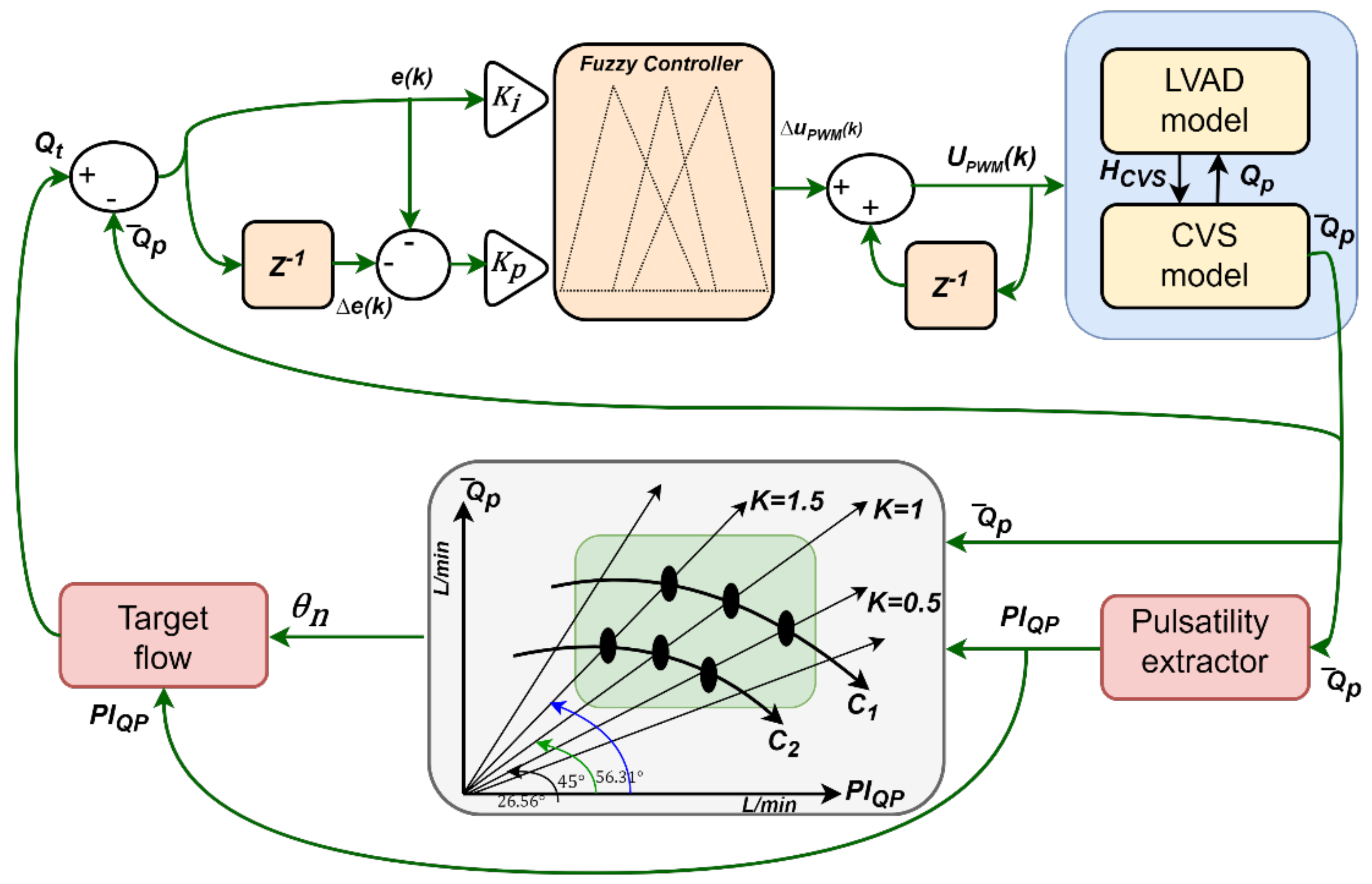
2.1. Control Strategy

According to the FSM of the heart, a rise in ventricular filling pressure or preload causes a stronger contraction and results in higher stroke volume and cardiac output. Therefore, changes in the heart’s inotropic condition will alter the cardiac function curve. Furthermore, the ventricular filling of pressure can also increase the heart’s myocardial contractility. In contrast, the opposite can be obtained by increasing the negative inotropic influence [29].
To design a controller that emulates the FSM of the heart, pump flow pulsatility is used as the LV filling pressure. The literature shows that the relationship between pump flow pulsatility and cardiac output can be assumed to be linear even when the aortic valve is closed [29]. Therefore, to implement the FSM, we set the flow–preload line (denoted by k) to intersect with the system flow–preload curve (denoted by c). The crossing represents the system’s operation point (indicated by a black dot), as shown in Figure 1. The operating point’s movement can form the LVAD pump speed at any given time. This means the LVAD speed increases when the pump flow pulsatility decreases and the mean flow increases, and vice versa. The characteristic of the flow–preload curve for the circulatory system is determined by different conditions, such as the contractility of the heart, the resistance of the systemic vascular system and the volume of the circulatory system.
A single gradient for the relationship (e.g., k = 1) would be sufficient to adjust the LV output (assumed to be pump flow) to short-term variations in the right ventricular output and, thus, LV preload (represented by pump flow pulsatility). Migration to different gradients can compensate for longer-term variations in LV contractility and the body’s metabolic requirements. A set of criteria for modifying the target flow–preload line based on upper and lower limits for both mean pump flow and pump flow pulsatility was devised to vary the control gradient. Further, an increase in total circulatory volume might cause a shift to the right in the flow–preload curve of the system (from c1 to c2).

2.2. Controller Design
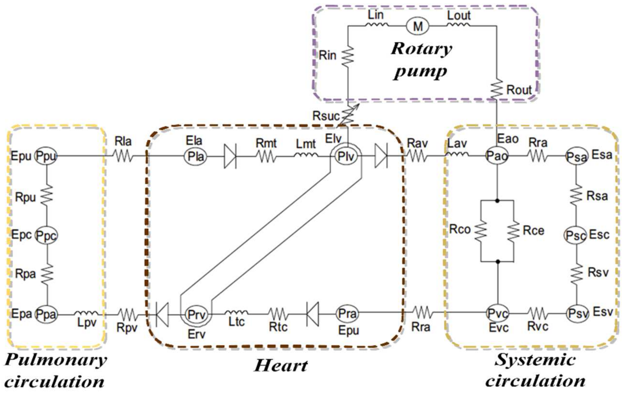
In this work, a proportional–integral (PI) controller and a PI type 1 fuzzy logic controller were used to implement this control strategy, as shown in Figure 1.
The PI controller was used to control the gradient angle (θ) of control lines as given:
θ = K p , θ . e r r Q p ¯ + e r r P I Q p + K i , θ e r r Q p ¯ + e r r P I Q p
where K p , θ and K i , θ are the proportional and integral gains, Q p ¯ represents the mean pump flow for a cardiac cycle, and P I Q p represents the pulsatility index of pump flow.
For the proposed controller, when either Q p ¯ or PI Q p exceeds its respective upper or lower limits, the gradient angle (θ) is automatically adjusted using a proportional integral controller. This is conducted to return the Q p ¯ or PI Q p to its respective upper or lower limits.
Then, the target pump flow ( Q t ) can be calculated based on Equation (1) as:
Q t = tan θ . PI Q p  
The PI type 1 FLC with error and change in error as inputs is used to regulate the Q t and Q p . The error of the control index is given as:
e k = Q p ¯ k Q t k
The change in e k is defined as:
Δ e k = e k e k 1
The voltage signal of the pulse-width modulation signal ( u P W M ) represents the output of FLC that drives the LVAD pump. Therefore, the update signal of u P W M is given by:
u P W M k + 1 = u P W M k + Δ u P W M k
Table 1 indicates the linguistic labels for the inputs and outputs. For the membership function, a triangular shape was used, as shown in Figure 2. In accordance with the fuzzy logic rules, the pump flow controller should make adjustments to the pump speed to minimize the error between the target flow and the mean pump flow. This will allow the controller to supply the body with the maximum amount of available blood while preventing adverse effects on the patients. In addition, the controller should run the pump correctly in various physiological situations, in accordance with the needs and requirements of the body.
The Mamdani method was also employed to implement the fuzzy rules, as given in Table 2. In this table, the linguistic labels for the inputs and outputs are defined as:
To obtain a robust result, a minimum operator was used to implement the proposed rules and maximum operator to implement the fuzzy relation as:
μ x y e ,   Δ e = min { μ x e ,   μ y Δ e }
μ x y z e ,   Δ e , Δ u P W M = max min μ x e ,   μ y Δ e ,   μ z Δ u P W M
where x   and   y are fuzzy sets defined on the input dimensions for e   and   Δ e , respectively, while z is a fuzzy set defined on the output dimension Δ u P W M .
In this method, a center of area method was used to implement the defuzzification process as:
Δ u P W M = i = 1 n μ z Δ u P W M i Δ u P W M i = 1 n μ z Δ u P W M i
where n is the number of quantization levels of the output.

2.3. Software Model

The control method was evaluated by using a dynamic model of the CVS that included descriptions of the left and right sides of the heart, the systemic and pulmonary circulations, and the LVAD pump, as shown in Figure 3. This model was used to simulate the interaction between the heart and the pump. The model was developed with the help of experimental data from five greyhounds that had an LVAD implanted and were subjected to a variety of different operating circumstances. These operating circumstances included changes in cardiac contractility, systemic vascular resistance, and total circulatory volume.
In this model, the relationship between pump flow ( Q p ), left ventricle pressure ( P l v ), aortic pressure ( P a o ), and differential pressure across the pump ( δ p ) was given by:
d Q p d t = δ p P a o P l v R i n + R o u t + R s u c Q p L i n + L o u t
where R i n and R o u t are inlet and outlet cannulae resistances, R s u c is suction resistance, and L i n and L o u t are inlet and outlet cannulae inertances.
A selection of model parameters was fitted by using least square parameter estimate methods in order to increase agreement with the experimental data and verify the model’s robustness and validity under a variety of different operating scenarios. More details on the validation of this model can be found in [30].

2.4. Simulation Protocols

The model was implemented in MATLAB (The Mathworks, Inc., Natick, MA, USA) using its inbuilt Ordinary Differential Equation (ODE) solver suite. Table 1 illustrates the CVS model parameters used to simulate the scenario protocols. In this work, rest, moderate, and exercise scenarios were obtained by varying the parameters of the total blood volume ( V t o t a l ) , left ventricle contractility ( E e s , l v ), right ventricle contractility ( E e s , r v ), and systematic vascular resistance ( R s a ), as given in Table 3. For instance, to assess the immediate response of the controller to short term circulatory changes, V t o t a l was linearly decreased by 50% and 70% over a period of 10 s to simulate the rest and moderate scenarios, respectively. Next, to evaluate the ability of the controller to adjust to more severe circulatory perturbations (severe HF by a change in the controller gradient), E e s , l v and E e s , r v were linearly increased by 20% and R s a was decreased by 50% over a period of 10 s. This technique was sufficient to move the operating point outside the zone of acceptability. In all simulations, the baseline, lower and upper limits for the controller gradient were set to 1, 0.5, and 1.5, respectively, the lower and upper limits for pump flow pulsatility were set to 1.5 and 6 L/min, respectively, while the lower and upper limits for mean pump flow were set to 2 and 6 L/min, respectively. A constant speed controller scenario was also evaluated. In this scenario, we disabled the controller and let the LVAD work at a constant speed by a reduction in V t o t a l with 500 mL in order to test the hemodynamic characteristic of the system. In all simulations, the gains for K p , θ and K i , θ were set by 1.25 and 0.75, respectively. Further, the gains for PI fuzzy were set by ( K p = 0.35 ) and ( K i = 1.56 ).

3. Results

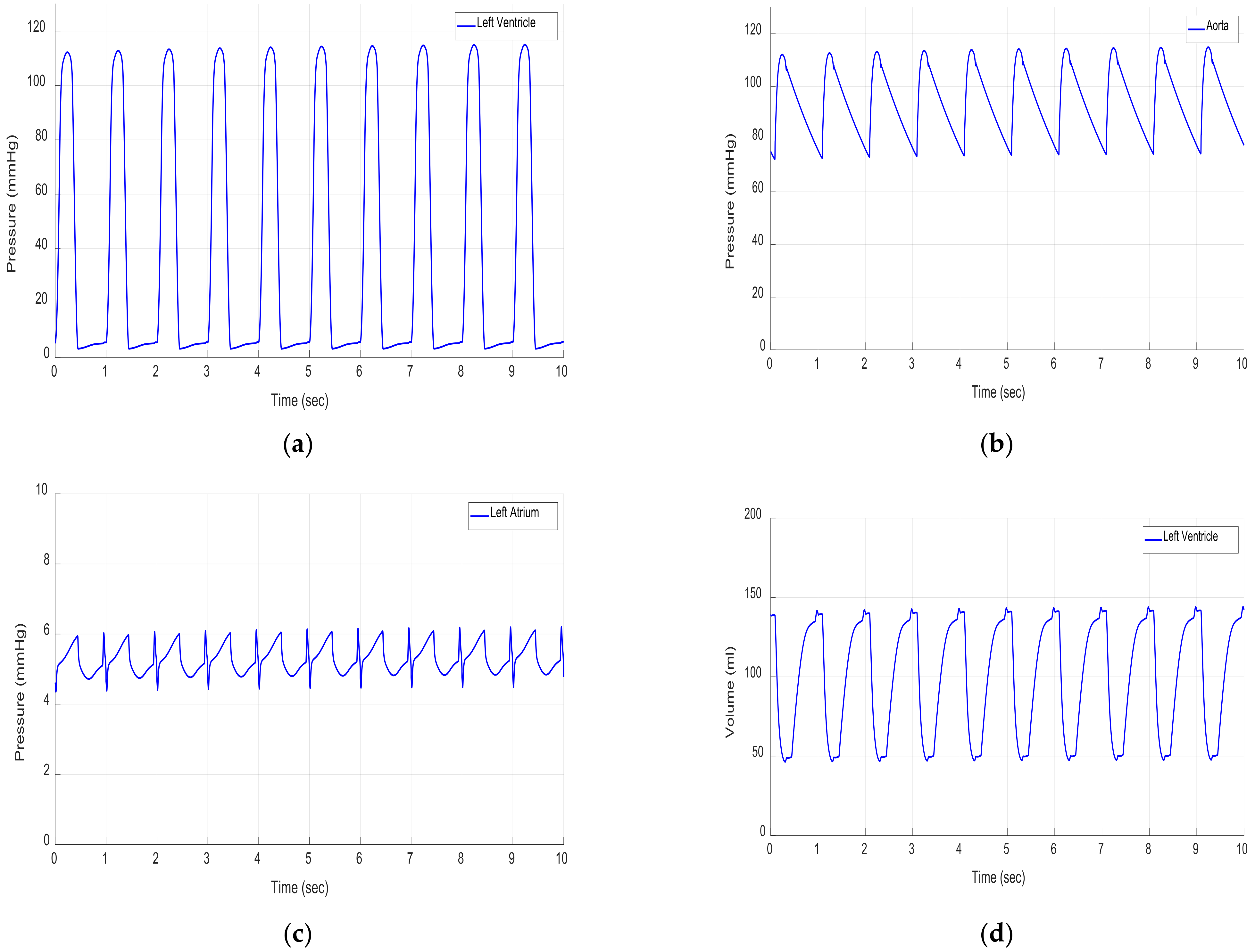
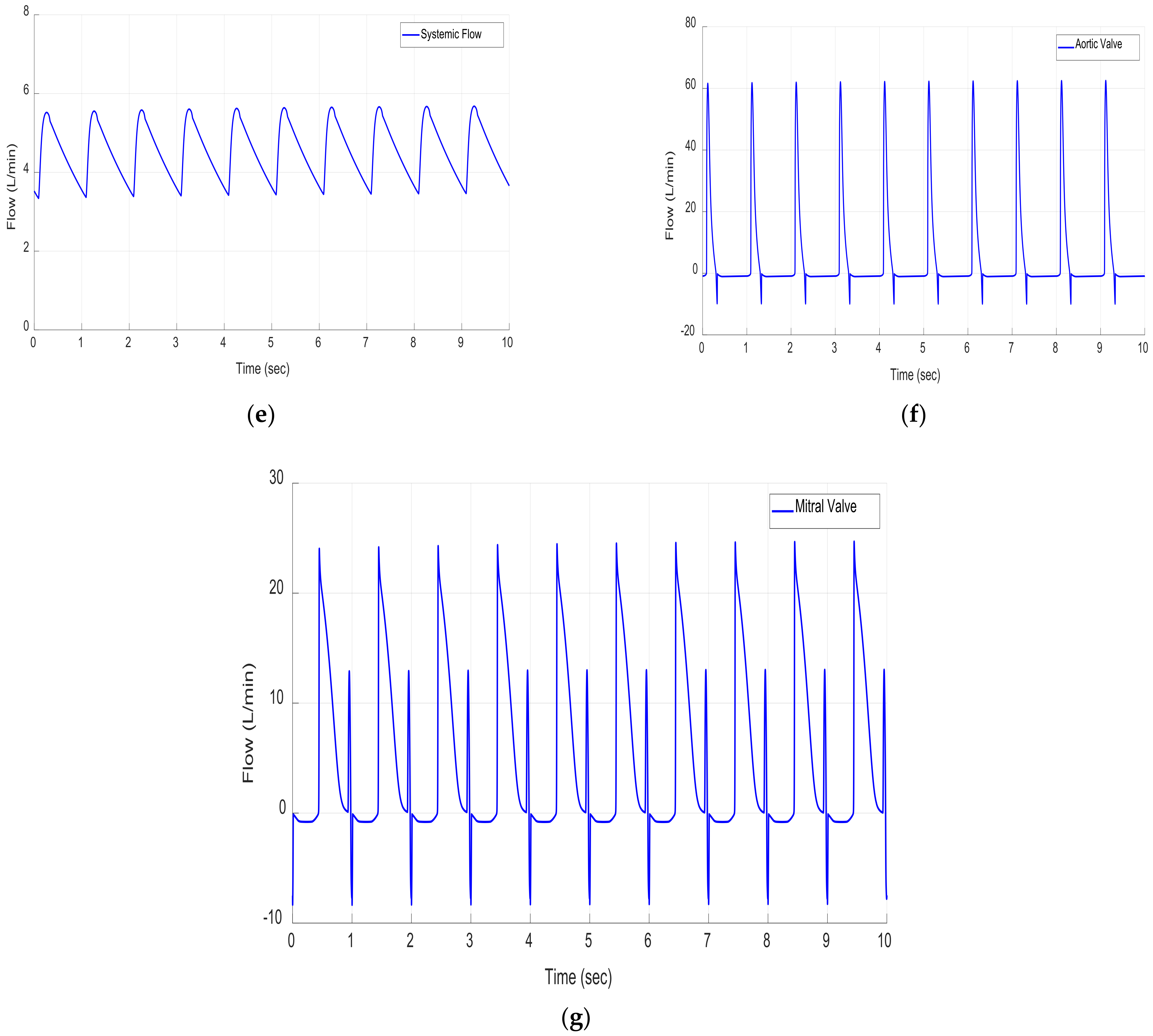
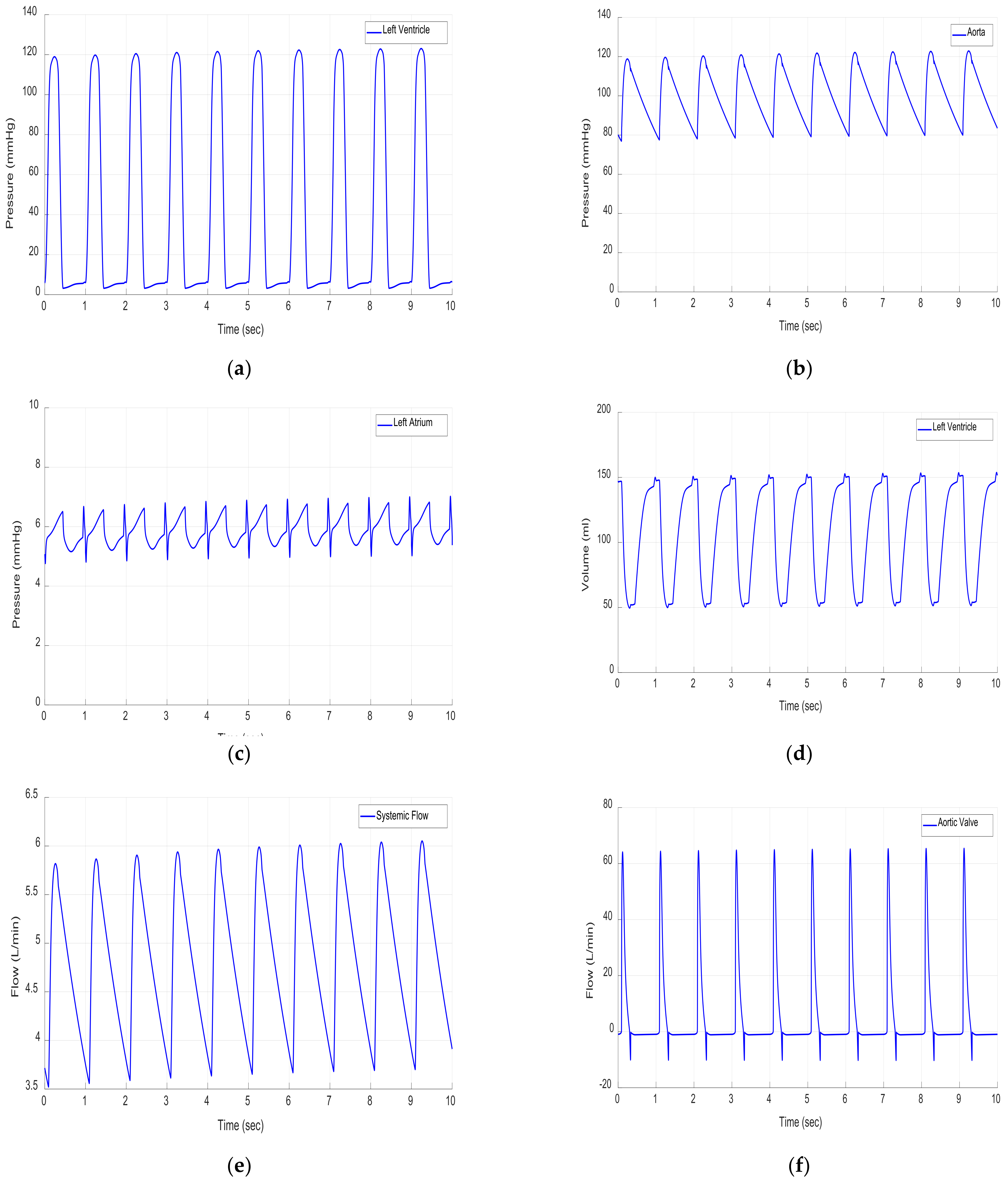
3.1. Results in Rest Scenario

Figure 4 shows the hemodynamic variable results in the rest scenario. During this scenario, the CVS parameters were changed in one cardiac cycle, as given in Table 3. The results demonstrated that the pressure for the LV, aortic valve (Ao), and left atrium (LA) were slightly decreased, as shown in Figure 4a–c. Additionally, the controller reduced the LV volume by 140 mL (Figure 4d) and maintained the systematic flow within a safe range of 4.5 L/min (Figure 4e). The results also show that the flow through the Ao and mitral valves was within the clinical limits (Figure 4f,g).

3.2. Results in Moderate Scenario

Figure 5 shows the hemodynamic variable results in the moderate scenario. During this scenario, the CVS parameters were changed in one cardiac cycle, as given in Table 3. The results demonstrated that the pressure for the LV, aortic valve (Ao), and left atrium (LA) was slightly increased, as shown in Figure 5a–c. Further, the controller reduced the LV volume by 147 mL (Figure 5d) and maintained the systematic flow within a safe range by a maximum of 5.8 L/min and a minimum of 3.5 L/min (Figure 4e). The results also show that the flow through the Ao and mitral valves was within the clinical limits (Figure 5f,g).

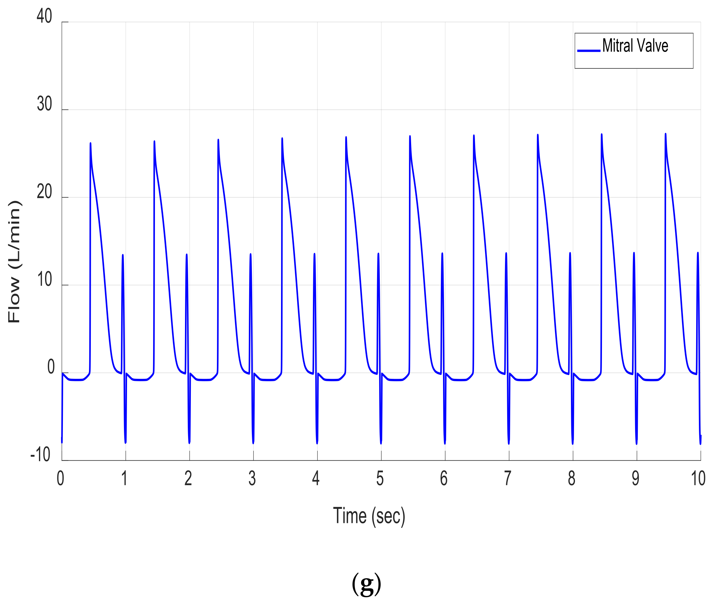
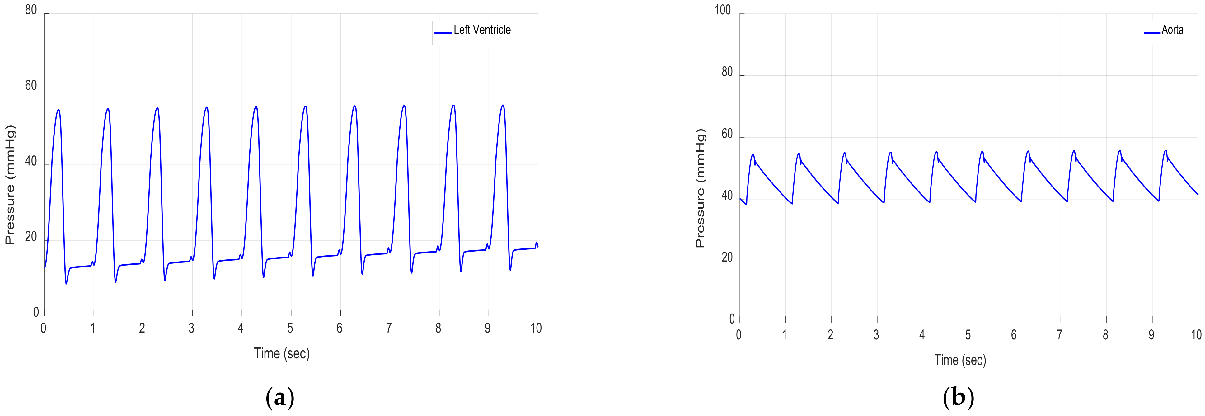
3.3. Results in Exercise Scenario

Figure 6 depicts the hemodynamic variable results in the exercise scenario. During this scenario, the CVS parameters were changed in one cardiac cycle, as given in Table 3. The results demonstrated that the pressure for LV, Ao, and LA was severely decreased, as shown in Figure 6a–c. For instance, the LV pressure dropped to 41 mmHg in systole and 20 mmHg in diastole pressure. Despite these severe decreases, the controller increased the LV volume by 287 mL at the beginning of the cycle, and this kept rising to 300 mL at the end of the cycle (Figure 6d). Further, the controller decreased the systematic flow within a safe range by 1.7 L/min (Figure 6e). The results also show that the flow through the Ao and mitral valves was within the clinical limits (Figure 6f,g). Additionally, Table 4 depicts the CVS hemodynamic parameters in a healthy person and in an HF patient with an LVAD.

3.4. Constant Speed Controllers

In this scenario, we disabled the controller and let the LVAD work at a constant speed to test the hemodynamic characteristic of the system. This scenario can be achieved by a quick reduction in the total circulatory volume, which decreases the pulsatility of pump flow dramatically. The reduced total circulatory volume caused a leftward shift of the left ventricular (LV) pressure volume loops, resulting in lower LV end-diastolic and end-systolic volumes, as well as lower end-diastolic and end-systolic pressures (Figure 7). In contrast, suction occurred in simulations that utilized a constant speed controller due to a substantial decrease in the LV preload. Therefore, to avoid this scenario, we must ensure that the set of operating point responds to the drop in total circulatory volume by decreasing the mean pump speed.

4. Discussion

Due to the parameter uncertainty, nonlinear components, and temporal delays present in the cardiovascular system, fuzzy logic control may offer improved functionality over some control methods [18]. These parameters include the flow rate, differential pressure, heart vascular resistances, and arteriovenous oxygen difference [31]. Different control strategies have been designed and implemented based on these hemodynamic variables [32,33]. For instance, pump flow controls allow the clinician to decide the target FR to ensure that the body achieves the perfusion requirements. Many researchers claim that the cardiac output and LVAD pump flow rate are the essential variables to adapt. For instance, Cysyk et al. [34] developed an inlet cannula tip for the continuous flow to control an LVAD. A waveform of current excitation with four platinum–iridium ring electrodes was applied to evaluate the model on HeartMate II. The ventricular size was measured during pump support using echocardiography to observe the ventricular unloading and suction prevention. Another study was conducted by Horobin et al. [35] to compare continuous and pulsatile flow through HeartWare HVAD. The pump ran at a constant speed and was controlled in a custom-built system. A different study was developed by Meki et al. [36] to design a novel physiological control algorithm to maintain continuous flow during ventricular prevention suction. The robustness of the controller was evaluated in different physiological conditions in the presence of hemodynamical variables.
In this work, we chose pump flow and pump flow pulsatility as the control parameters to drive an LVAD. The pump flow variable was used as the preload parameter. This parameter is widely used and is usually referred to as left ventricle end-diastolic pressure (Plved). Unlike our work, a recent study conducted by Fetanat et al. [37] used a measure of the Plved parameter to automatically adapt the LVAD using model-free adaptive control in combination with the PID controller. The control algorithm was used to track the target end-diastolic pressure of the reference point within the usual range of 3 to 15 mmHg. This approach was tested successfully in each of the six patient scenarios by simulating 100 different patient conditions. The results illustrated that the performance of the controller was able to maintain the cardiac flow.
The variable pulsatility index of flow (PIF) is usually obtained by the linear regression between the pump flow’s maximum derivative and the peak-to-peak value. In 2005, Misgeld [38] developed a robust and self-tuning controller based on the pulsatility index, HR, and mean blood flow. The controller was designed using PI and H-infinity methods. The method was successfully validated using a circulatory hydrodynamic simulator combined with an LVAD. A different study was conducted by Choi et al. [39] to develop a hemodynamical control method utilizing a pulsatility ratio of pump flow to maintain the physiological perfusion. A difference pressure parameter was used as a PERT from the control algorithm, which considered preload, afterload, and contractility. The results depicted that the control method automatically adjusted the pump speed within the safe operating mode [39].
In 2008, Arndt et al. proposed a control strategy based on the index of pulsatility, which was calculated from the pressure difference. The control technique was applied based on external and internal loops of FR to control the aortic valve opening and closing. First, the outer loop was used to regulate the gradient pulsatility index in the reference value’s presence. Then, the inner loop was used to control the pulsatility index [15]. Another study used a cascaded control loop to regulate LVAD pump speed based on the measured pressure difference. This method presented two operating modes for ranging between partial and full assist to adjust the pump speed. In addition, the technique proposed a robust predictive controller, and stability was achieved in different physiological conditions and operating points [40].
Generally, the differential pressure variable for LVADs is defined as the pressure across the pump or the pressure between the LV and aorta; the pressure between the aortic valve and pump outlet (afterload); the pressure between the inlet and outlet pumps; or the end-diastolic ventricular pressure (preload). This variable has been widely used in different studies to maintain the physiological demand by the human body. For instance, Wang et al. [41] developed an approach to prevent ventricular suction based on the differential pressure between the LV and aorta for axial and centrifugal LVADs. The method was designed using a gain-scheduled PI controller and evaluated in silico under varied conditions to provide physiologic perfusion. Similarly, Giridharan et al. [42] used a gain-scheduled (PI) non-linear controller to maintain the differential pressure between the LV and the aorta. The same authors also developed a sensorless estimator to estimate the differential pressure using an extended Kalman filter. This estimator was used to implement the physiological control algorithm using intrinsic pump parameters [43].
The use of a motor current as a control variable for LVADs has been investigated and evaluated. In 2012, Faragallah et al. [44] used a motor current to develop an automatic controller to maintain a CF from the weak LV to the ascending aorta. The method was established by observing the pump flow output and estimating the systemic vascular resistance. The simulation results demonstrated that the system was stable and rapidly controlled. Another study conducted by Endo et al. [45] used the index of motor current amplitude. In this study, the pump speed was automatically controlled within a safe operating mode by observing the motor current’s characteristic curve in changing preload, afterload, and contractility conditions. In addition, Choi et al. used the motor current variable to estimate the pump flow and adjust the LVAD pump. The method was implemented in the FLC to optimize the physiological perfusion while assuming that the natural heart can still produce some pumping action. In vivo tests demonstrated that the controller was able to provide enough blood and prevent ventricular suction [18].
In the last few decades, the H-infinity ( H ) optimization approach has continued to be investigated [29,46]. This control has been found to be efficient and effective, and it can be used for the creation of time-variant and linear control systems. However, these system applications are still not common in the field of LVAD control. In 2005, Misgeld et al. [38] designed a tuned control on the VAD pump and compared this to the PI and general predictive controller. The controllers were validated on the hydrodynamic simulator in a wide range of operating points with different physiological conditions in the presence of disturbances. The results demonstrated that the VAD pump is more robust in performance compared with the PI and general predictive controller.
The findings of this study are susceptible to important limitations because the software model did not take reflex control and auto-regulatory systems into account. The control strategy now being used may be significantly impacted by the reflex and autoregulatory system capacity to automatically adapt to transient changes in the cardiovascular system. The study demonstrated that the baroreceptor response was significant in both HF and exercise conditions, indicating that further model development to incorporate the reflex control system is necessary in order to assess the controller [47]. In the future, it will be crucial to consider the control algorithms created for both animal testing and clinical trials.

5. Conclusions

This work presented a physiological controller to drive an LVAD pump for heart failure patients. The controller aims to automatically regulate the mean pump flow and target flow based on the physiological demand of the body. The Frank–Starling mechanism (FSM) technique was designed and implanted to achieve this aim. In this technique, the FSM is emulated by shifting the operating point of the patient through the preload control lines within the designed boundary zone (green area) to avoid ventricular collapse or overperfusion. The slope of these lines is changed using the PI controller. The method also uses a PI type 1 fuzzy logic controller to update the speed of LVAD based on the physiological conditions of CVS.
MATLAB software was utilized for the lumped parameter model of the CVS with an LVAD throughout the design and analysis of the control technique. This model’s parameters, which were used to simulate HF conditions, were set based on clinical data. Three scenarios: rest, moderate, and exercise, were proposed to examine this control strategy using a lumped parameter model. In all scenarios, the CVS parameters were varied by changing total blood volume, left ventricle contractility, right ventricle contractility, and systematic vascular resistance to demonstrate the rest and severity of conditions of HF patients.
The hemodynamic results show that the proposed control method was able to regulate the pump flow within the accepted clinical state. Furthermore, the system indicated that all hemodynamic parameters, such as left ventricle pressure, aortic pressure, left atrial pressure, left ventricle volume, and systematic flow were within the acceptable clinical range. The results demonstrated that the design method also prevented ventricular collapse or overperfusion.

Author Contributions

Conceptualization, M.B.; methodology, M.B. and A.A. (Ahmad Alassaf); software, M.B., A.A. (Ahmed Alassaf), K.A., I.A. and Y.A.; validation, M.B., A.A. (Ahmad Alassaf), A.S., I.A., A.A. (Abdulrahman Alqahtani) and M.A.A.; formal analysis, M.B., A.S., A.A. (Abdulrahman Alqahtani), M.A.A. and Y.A.; visualization, all authors were involved; writing—original draft preparation, all authors were involved in the manuscript writing. All authors have read and agreed to the published version of the manuscript.

Funding

This research was funded by the deputyship for Research and Innovation, Ministry of Education, Saudi Arabia, grant number IFP-2020-43.

Institutional Review Board Statement

Not applicable.

Informed Consent Statement

Not applicable.

Data Availability Statement

Not applicable.

Acknowledgments

The authors extend their appreciation to the deputyship for Research and Innovation, Ministry of Education in Saudi Arabia for funding this research work through the project number IFP-2020-43.

Conflicts of Interest

The authors declare no conflict of interest.

References

  1. Gwak, K.W.; Ricci, M.; Snyder, S.; Paden, B.E.; Boston, J.R.; Simaan, M.A.; Antaki, J.F. In vitro evaluation of multiobjective hemodynamic control of a heart-assist pump. ASAIO J. 2005, 51, 329–335. [Google Scholar] [CrossRef] [PubMed]
  2. Ketelhut, M.; Schrödel, F.; Stemmler, S.; Roseveare, J.; Hein, M.; Gesenhues, J.; Albin, T.; Abel, D. Iterative Learning Control of a Left Ventricular Assist Device. IFAC-PapersOnLine 2017, 50, 6684–6690. [Google Scholar] [CrossRef]
  3. Wu, Y.; Allaire, P.E.; Tao, G.; Adams, M.; Liu, Y.; Wood, H.; Olsen, D.B. A bridge from short-term to long-term left ventricular assist device—Experimental verification of a physiological controller. Artif. Organs 2004, 28, 927–932. [Google Scholar] [CrossRef] [PubMed]
  4. Amacher, R.; Asprion, J.; Ochsner, G.; Tevaearai, H.; Wilhelm, M.J.; Plass, A.; Amstutz, A.; Vandenberghe, S.; Schmid Daners, M. Numerical optimal control of turbo dynamic ventricular assist devices. Bioengineering 2014, 1, 22–46. [Google Scholar] [CrossRef] [Green Version]
  5. Son, J.; Du, D.; Du, Y. Modelling and control of a failing heart managed by a left ventricular assist device. Biocybern. Biomed. Eng. 2020, 40, 559–573. [Google Scholar] [CrossRef]
  6. Ng, B.C.; Smith, P.A.; Nestler, F.; Timms, D.; Cohn, W.E.; Lim, E. Application of Adaptive Starling-Like Controller to Total Artificial Heart Using Dual Rotary Blood Pumps. Ann. Biomed. Eng. 2017, 45, 567–579. [Google Scholar] [CrossRef]
  7. Wu, Y. Adaptive physiological speed/flow control of rotary blood pumps in permanent implantation using intrinsic pump parameters. ASAIO J. 2009, 55, 335–339. [Google Scholar] [CrossRef]
  8. Chang, Y.; Gao, B.; Gu, K. A model-free adaptive control to a blood pump based on heart rate. ASAIO J. 2011, 57, 262–267. [Google Scholar] [CrossRef]
  9. Gaddum, N.R.; Stevens, M.; Lim, E.; Fraser, J.; Lovell, N.; Mason, D.; Timms, D.; Salamonsen, R. Starling-like flow control of a left ventricular assist device: In vitro validation. Artif. Organs 2014, 38, E46–E56. [Google Scholar] [CrossRef]
  10. Voigt, O.; Benkowski, R.J.; Morello, G.F. Suction detection for the MicroMed DeBakey left ventricular assist device. ASAIO J. 2005, 51, 321–328. [Google Scholar] [CrossRef]
  11. Wang, Y.; Faragallah, G.; Divo, E.; Simaan, M.A. Feedback control of a rotary left ventricular assist device supporting a failing cardiovascular system. In Proceedings of the American Control Conference (IEEE ACC), Montreal, QC, Canada, 27–29 June 2012; pp. 1137–1142. [Google Scholar]
  12. Tan, Y.; Nešić, D.; Mareels, I. On non-local stability properties of extremum seeking control. Automatica 2006, 42, 889–903. [Google Scholar] [CrossRef] [Green Version]
  13. Gwak, K.W. Application of extremum seeking control to turbodynamic blood pumps. ASAIO J. 2007, 53, 403–409. [Google Scholar] [CrossRef]
  14. Arndt, A.; Nüsser, P.; Lampe, B. Fully autonomous preload-sensitive control of implantable rotary blood pumps. Artif. Organs 2010, 34, 726–735. [Google Scholar] [CrossRef]
  15. Arndt, A.; Nüsser, P.; Graichen, K.; Müller, J.; Lampe, B. Physiological control of a rotary blood pump with selectable therapeutic options: Control of pulsatility gradient. Artif. Organs 2008, 32, 761–771. [Google Scholar] [CrossRef]
  16. Ferreira, A.; Boston, J.R.; Antaki, J.F. A control system for rotary blood pumps based on suction detection. IEEE Trans. Biomed. Eng. 2009, 56, 656–665. [Google Scholar] [CrossRef]
  17. Casas, F.; Ahmed, N.; Reeves, A. Minimal sensor count approach to fuzzy logic rotary blood pump flow control. ASAIO J. 2007, 53, 140–146. [Google Scholar] [CrossRef]
  18. Choi, S.; Antaki, J.F.; Boston, R.; Thomas, D. A sensorless approach to control of a turbodynamic left ventricular assist system. IEEE Trans. Control Syst. Technol. 2001, 9, 473–482. [Google Scholar] [CrossRef] [Green Version]
  19. Huang, F.; Ruan, X.; Fu, X. Pulse-pressure-enhancing controller for better physiologic perfusion of rotary blood pumps based on speed modulation. ASAIO J. 2014, 60, 269–279. [Google Scholar] [CrossRef]
  20. Casas, F.; Orozco, A.; Smith, W.A.; De Abreu-García, J.A.; Durkin, J. A fuzzy system cardio pulmonary bypass rotary blood pump controller. Expert Syst. Appl. 2004, 26, 357–361. [Google Scholar] [CrossRef]
  21. Bakouri, M.; Salamonsen, R.F.; Savkin, A.V.; Alomari, A.H.H.; Lim, E.; Lovell, N.H. A Sliding Mode-Based Starling-Like Controller for Implantable Rotary Blood Pumps. Artif. Organs 2014, 38, 587–593. [Google Scholar] [CrossRef]
  22. Bakouri, M.A.; Savkin, A.V.; Alomari, A.H. Nonlinear modelling and control of left ventricular assist device. Electron. Lett. 2015, 51, 613–615. [Google Scholar] [CrossRef]
  23. Bakouri, M. Evaluation of an advanced model reference sliding mode control method for cardiac assist device using a numerical model. IET Syst. Biol. 2018, 12, 68–72. [Google Scholar] [CrossRef] [Green Version]
  24. Chang, Y.; Gao, B. A global sliding mode controller design for an intra-aorta pump. ASAIO J. 2010, 56, 510–516. [Google Scholar] [CrossRef]
  25. Koh, V.C.; Pauls, J.P.; Wu, E.L.; Stevens, M.C.; Ho, Y.K.; Lovell, N.H.; Lim, E. A centralized multi-objective model predictive control for a biventricular assist device: An in vitro evaluation. Biomed. Signal Process. Control 2020, 59, 137–148. [Google Scholar] [CrossRef]
  26. Koh, V.C.; Ho, Y.K.; Stevens, M.C.; Salamonsen, R.F.; Lovell, N.H.; Lim, E. Synergy of first principles modelling with predictive control for a biventricular assist device: In silico evaluation study. In Proceedings of the 2017 39th Annual International Conference of the IEEE Engineering in Medicine and Biology Society (EMBC), Jeju, Korea, 11–15 July 2017; pp. 1291–1294. [Google Scholar]
  27. Ng, B.C.; Salamonsen, R.F.; Gregory, S.D.; Stevens, M.C.; Wu, Y.; Mansouri, M.; Lovell, N.H.; Lim, E. Application of multiobjective neural predictive control to biventricular assistance using dual rotary blood pumps. Biomed. Signal Process. Control 2018, 39, 81–93. [Google Scholar] [CrossRef]
  28. Alomari, A.H.; Javed, F.; Savkin, A.V.; Lim, E.; Salamonsen, R.F.; Mason, D.G.; Lovell, N.H. Non-invasive measurements based model predictive control of pulsatile flow in an implantable rotary blood pump for heart failure patients. In Proceedings of the 2011 19th Mediterranean Conference on Control & Automation (MED), Corfu, Greece, 20–23 June 2011; pp. 491–496. [Google Scholar]
  29. Bakouri, M.; Alassaf, A.; Alshareef, K.; Abdelsalam, S.; Ismail, H.F.; Ganoun, A.; Alomari, A.H. An Optimal H-Infinity Controller for Left Ventricular Assist Devices Based on a Starling-like Controller: A Simulation Study. Mathematics 2022, 10, 731. [Google Scholar] [CrossRef]
  30. Lim, E.; Dokos, S.; Salamonsen, R.F.; Rosenfeldt, F.L.; Ayre, P.J.; Lovell, N.H. Numerical Optimization Studies of Cardiovascular-Rotary Blood Pump Interaction. Artif. Organs 2012, 36, 110–124. [Google Scholar] [CrossRef]
  31. Stefanovska, A. Physics of the human cardiovascular system. Contemp. Phys. 1999, 40, 31–55. [Google Scholar] [CrossRef]
  32. Alomari, A.H.; Savkin, A.V.; Stevens, M.; Mason, D.G.; Timms, D.L.; Salamonsen, R.F.; Lovell, N.H. Developments in control systems for rotary left ventricular assist devices for heart failure patients: A review. Physiol. Meas. 2013, 34, R1. [Google Scholar] [CrossRef]
  33. Bozkurt, S. Physiologic outcome of varying speed rotary blood pump support algorithms: A review study. Australas. Phys. Eng. Sci. Med. 2016, 39, 13–28. [Google Scholar] [CrossRef]
  34. Cysyk, J.; Newswanger, R.; Popjes, E.; Pae, W.; Jhun, C.S.; Izer, J.; Weiss, W.; Rosenberg, G. Cannula tip with integrated volume sensor for rotary blood pump control: Early-stage development. ASAIO J. 2019, 65, 318–323. [Google Scholar] [CrossRef] [PubMed]
  35. Horobin, J.T.; Simmonds, M.J.; Nandakumar, D.; Gregory, S.D.; Tansley, G.; Pauls, J.P.; Girnghuber, A.; Balletti, N.; Fraser, J.F. Speed Modulation of the HeartWare HVAD to Assess In Vitro Hemocompatibility of Pulsatile and Continuous Flow Regimes in a Rotary Blood Pump. Artif. Organs 2018, 42, 879–890. [Google Scholar] [CrossRef] [PubMed]
  36. Meki, M.; Wang, Y.; Sethu, P.; Ghazal, M.; El-Baz, A.; Giridharan, G. A Sensorless Rotational Speed-Based Control System for Continuous Flow Left Ventricular Assist Devices. IEEE Trans. Biomed. Eng. 2020, 67, 1050–1060. [Google Scholar] [CrossRef] [PubMed]
  37. Fetanat, M.; Stevens, M.; Hayward, C.; Lovell, N.H. A Physiological Control System for an Implantable Heart Pump That Accommodates for Interpatient and Intrapatient Variations. IEEE Trans. Biomed. Eng. 2020, 67, 1167–1175. [Google Scholar] [CrossRef] [PubMed] [Green Version]
  38. Misgeld, B.J.; Werner, J.; Hexamer, M. Robust and self-tuning blood flow control during extracorporeal circulation in the presence of system parameter uncertainties. Med. Biol. Eng. Comput. 2005, 43, 589–598. [Google Scholar] [CrossRef] [PubMed]
  39. Choi, S.; Boston, R.; Antaki, J.F. Hemodynamic controller for left ventricular assist device based on pulsatility ratio. Artif. Organs 2007, 31, 114–125. [Google Scholar] [CrossRef]
  40. Arndt, A.; Nüsser, P.; Lampe, B.P.; Müller, J. Physiological control of a rotary left ventricular assist device: Robust control of pressure pulsatility with suction prevention and suppression. IFMBE Proc. 2009, 25, 775–778. [Google Scholar]
  41. Wang, Y.; Koenig, S.C.; Slaughter, M.S.; Giridharan, G.A. Rotary blood pump control strategy for preventing left ventricular suction. ASAIO J. 2015, 61, 21–30. [Google Scholar] [CrossRef]
  42. Giridharan, G.A.; Skliar, M. Nonlinear controller for ventricular assist devices. Artif. Organs 2002, 26, 980–984. [Google Scholar] [CrossRef]
  43. Giridharan, G.A.; Skliar, M. Physiological control of blood pumps using intrinsic pump parameters: A computer simulation study. Artif. Organs 2006, 30, 301–307. [Google Scholar] [CrossRef]
  44. Faragallah, G.; Wang, Y.; Divo, E.; Simaan, M. A new control system for left ventricular assist devices based on patient-specific physiological demand. Inverse Probl. Sci. Eng. 2012, 20, 721–734. [Google Scholar] [CrossRef] [Green Version]
  45. Endo, G.; Araki, K.; Kojima, K.; Nakamura, K.; Matsuzaki, Y.; Onitsuka, T. The index of motor current amplitude has feasibility in control for continuous flow pumps and evaluation of left ventricular function. Artif. Organs 2001, 25, 697–702. [Google Scholar] [CrossRef]
  46. Rigatos, G.; Siano, P.; Raffo, G. A nonlinear H-infinity control method for multi-DOF robotic manipulators. Nonlinear Dyn. 2017, 88, 329–348. [Google Scholar] [CrossRef]
  47. Creager, M.A. Baroreceptor reflex function in congestive heart failure. Am. J. Cardiol. 1992, 69, 10–16. [Google Scholar] [CrossRef]
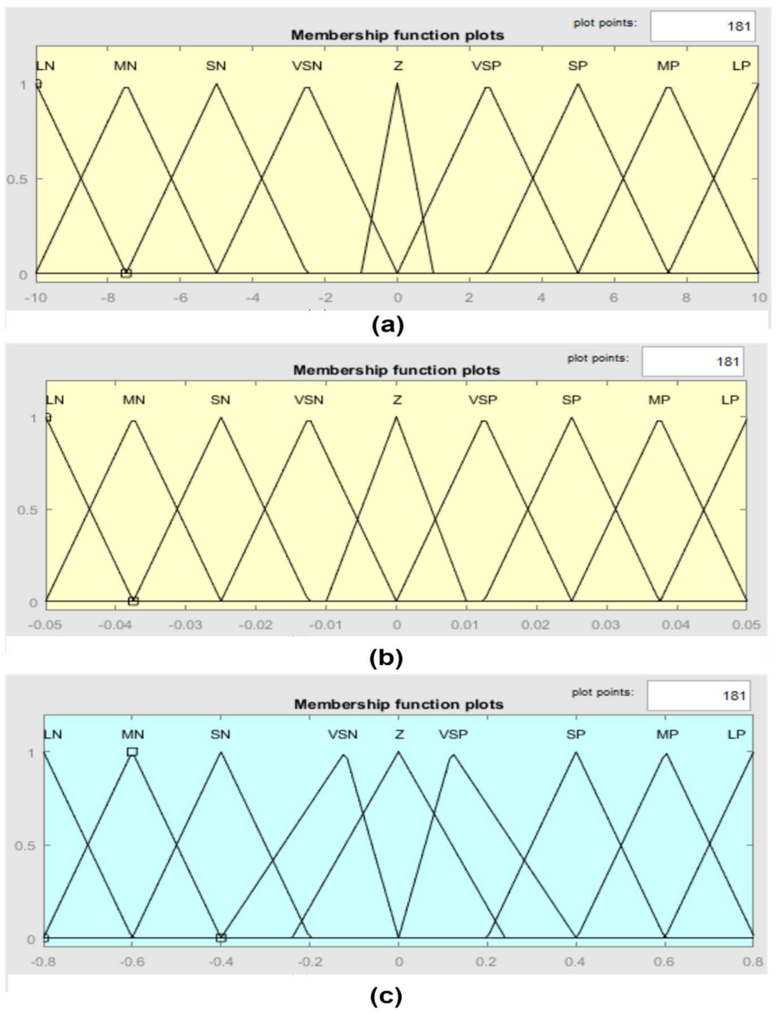
Figure 1. Block diagram of the control system.
Mathematics 10 02251 g001
Figure 2. Membership function for the inputs and outputs; (a) input variable (e); (b) input variable Δ ( e ) ; (c) output variable ( u P W M ).
Mathematics 10 02251 g002
Figure 3. Electrical equivalent circuit analogue of CVS–LVAD interaction. R i n : inlet cannula resistances; R o u t : outlet cannula resistances; L i n : inlet cannula inertances; L o u t : outlet cannula inertances; R s u c : suction resistance; and P t h o r 1 and P t h o r 2 : intrathoracic pressures.
Mathematics 10 02251 g003
Figure 4. Hemodynamic variable results for the rest condition; (a) left ventricle pressure; (b) aortic pressure; (c) left atrium pressure; (d) left ventricle volume; (e) systemic flow; (f) aortic valve flow; (g) mitral valve flow.
Mathematics 10 02251 g004aMathematics 10 02251 g004b
Figure 5. Hemodynamic variable results for the moderate healthy condition; (a) left ventricle pressure; (b) aortic pressure; (c) left atrium pressure; (d) left ventricle volume; (e) systemic flow; (f) aortic valve flow; (g) mitral valve flow.
Mathematics 10 02251 g005aMathematics 10 02251 g005b
Figure 6. Hemodynamic variable results for a severe HF condition; (a) left ventricle pressure; (b) aortic pressure; (c) left atrium pressure; (d) left ventricle volume; (e) systemic flow; (f) aortic valve flow; (g) mitral valve flow.
Mathematics 10 02251 g006aMathematics 10 02251 g006b
Figure 7. Hemodynamic characteristic of preload and afterload in severe HF condition.
Mathematics 10 02251 g007
Table 1. Linguistic labels for the inputs and outputs.
LabelLNMNSNVSNZVSPSPMPLP
DefinitionLarge
negative
Medium
negative
Small
negative
Very small
negative
ZeroVery small
positive
Small
Positive
Medium positiveLarge
positive
Table 2. Rules of FLC.
ΔeLNMNSNZSPMPLP
e
LNLNLNLNMNSNVSNZ
MNLNLNMNSNVSNZVSP
SNLNMNSNVSNZVSPSP
ZMNSNVSNZVSPSPMP
SPSNVSNZVSPSPMPLP
MPVSNZVSPSPMPLPLP
LPZVSPSPMPLPLPLP
Table 3. CVS model parameters used to simulate HF conditions.
VariableUnitHealthyHeart Failure (HF)
Total blood volume ( V t o t a l ) mL53005800
Left ventricle contractility ( E e s , l v )mm Hg/mL1.72350.5322
Right ventricle contractility ( E e s , r v )mm Hg/mL3.54430.7100
Systematic vascular resistance ( R s a )mm Hg·s/mL0.74111.1100
Table 4. CVS hemodynamic parameters in a healthy person and a HF patient with an LVAD.
Hemodynamic ParametersUnitHealthyHF Patient with an LVAD
RestModerateExercise
Left ventricle pressuremmHg12011211855
Aortic pressuremmHg12011312054.66
Left atrial pressuremmHg64.78614.87
Left ventricle volumemL150140150287
Systematic flowL/min65.561.75
Publisher’s Note: MDPI stays neutral with regard to jurisdictional claims in published maps and institutional affiliations.

