Article

Robot Operations for Pine Tree Resin Collection

1
Department of Manufacturing Engineering, Georgia Southern University, Statesboro, GA 30458, USA
2
B&L Naval Stores Inc., Hinesville, GA 31313, USA
*
Author to whom correspondence should be addressed.
Technologies 2021, 9(4), 79; https://doi.org/10.3390/technologies9040079
Submission received: 28 September 2021 / Revised: 13 October 2021 / Accepted: 18 October 2021 / Published: 27 October 2021
(This article belongs to the Special Issue Advances and Innovations in Manufacturing Technologies)

Abstract

:
A robotic technology consisting of an industrial robot mounted on an autonomous rover used to tap slash pine trees and collect their oleoresin for processing is introduced, and the technological challenges related to the robotic operations are discussed in detail. Unlike the case of industrial automated manufacturing systems where the relative position between the tool and workpiece can be controlled within a few hundredths of a millimeter accuracy, when used in highly unstructured environments characteristic to forestry or agriculture, the positioning accuracy between the industrial robot and the target on which it operates can be much lower than the accuracy required for the operation of the industrial robot. The paper focuses on presenting the robotic operations necessary for drilling three converging boreholes in the pine tree, spraying the boreholes with chemicals, inserting a plastic tube with pre-attached collection bag in one borehole and inserting two plugs in other two boreholes. The challenges related to performing these robotic operations in conditions of large variations in the actual shape of the pine tree trunk and variations in the relative position between the robot and the pine tree after the autonomous vehicle positions itself in front of the tree are presented. The technical solutions used to address these challenges are also described. The strategies used to programmatically adjust the robot toolpath based on detection of the borehole entry points and on the measurement of the insertion force are presented.

1. Introduction

Industrial automated manufacturing systems using computer numerical control (CNC) machines and industrial robots are structured environments in which the relative position between the tool performing the manufacturing operation and the workpiece can be commonly controlled within a few hundredths of a millimeter accuracy. There has been proposed automated equipment consisting of industrial robots installed on autonomous rovers to perform operations in forestry and agriculture [1,2,3,4]. Forestry and agricultural environments can be semi-structured, as is the case of plantations [5,6,7,8,9], or highly unstructured, as is the case of wild forests [2,3]. In these applications, the autonomous rover identifies the targets, for example trees, approaching them within an operating distance after which the industrial robot performs specific operations on the target. In such unstructured environments, the positioning accuracy of the rover relative to the target is typically much lower than the submillimeter-scale accuracy required for the operation of the industrial robot. The reasons for which the positional accuracy of wheeled vehicles cannot be generally controlled at submillimeter-scale are the following: (i) the wheels are typically not actuated by stepper of servo motors—the only ones which can control their position at a fraction of a degree; (ii) the relatively large wheels radii (hundreds of millimeters) amplify the angular error of the actuating motor; (iii) the large manufacturing tolerances of the wheels and (iv) the soft and/or irregular terrains on which wheeled vehicles operate.
One such application is the robotic technology for tapping slash pine trees and collecting their oleoresin for processing using an autonomous robotic forest rover [1]. The technology consists of a forest rover equipped with an industrial robot (Figure 1) that identifies healthy, mature pine trees larger than 8 inch in diameter, approaches them and performs the robotic operations required for tapping the trees. This technology aims to replace the traditional labor-intensive manual work required in the collection of slash pine oleoresin [10] and to revitalize the once thriving naval stores industry in the southeast United States [11].
Secretion of oleoresin is an efficient defense-response inducer when pine trees are locally wounded. Based on this fact, there have been traditionally developed two tapping techniques for harvesting pine oleoresin [10,12,13]: (a) the bark removal method, in which bark streaks are periodically removed and the resin is collected in open containers, and (b) the borehole method, in which boreholes are drilled into the tree trunk and the oleoresin is collected in closed vessels attached to tubes inserted into the boreholes.
This paper demonstrates for the first time the feasibility of the operations required for tapping pine trees by an industrial robot using the borehole method and represents a first step in demonstrating the fully autonomous harvesting process.
Traditionally, the work required for tapping slash pine trees and collecting their oleoresin using the borehole method includes the following activities: (i) identifying slash pine trees having a trunk of at least 8 inches in diameter at chest height; (ii) drilling three converging boreholes in the tree trunk at angles that allow the flow of oleoresin due to gravity; (iii) manually spraying the three holes with resin flow stimulating chemicals and the pine tree trunk with insecticide; (iv) manually tapping one of the holes with a polymer pipe connected to a collection vessel and (v) manually capping the remaining two holes to prevent them from desiccating and the turpentine from evaporating. These activities occur at the beginning of the oleoresin harvesting season when a worker typically taps hundreds of pine trees daily. State-of-the-art attempts to automate the process consist of hydraulic drills and spray nozzles attached to a delivery vehicle such as a tractor or bobcat driven and actuated by a human operator [14]. Besides drilling and spraying the holes, the rest of the operations are performed manually. To the best of our knowledge, there have been no previous attempts to fully automate the process using the borehole method. However, we notice the demonstration of harvesting latex from rubber trees in China using a robot mounted on an autonomous rover using the bark removal method [15].
The demonstration of the automated technology requires addressing two major but unrelated challenges: (a) the demonstration of the industrial robot’s capability to perform the tapping operations in conditions of large variations in the actual shape of the pine tree trunk and variations in the relative position between the robot and the tree after the rover places itself in front of it and (b) the demonstration of the rover’s capability to identify mature slash pine trees and to navigate towards them.
This paper focusses on presenting the challenges related to performing the robotic operations required for tapping slash pine trees and collecting their oleoresin for processing in conditions of large variations in the shape of the tree trunk and in the relative position between the industrial robot and the tree after the rover on which the robot is mounted reaches the destination, as well as the technical approach used to address these challenges. The paper presents the experimental setup, the strategy and the results used to demonstrate the robotic operations. The robotic operation cycle includes loading the spindle from the tool stand and drilling three converging boreholes in the pine tree at angles that allow the flow of oleoresin due to gravity; replacing the spindle with a nozzle and spraying the boreholes with resin flow stimulating chemicals and insecticide; replacing the nozzle with a 3-fingers gripper, picking a plastic tube with pre-attached collection bag and tapping one borehole, then picking two plugs and capping the other boreholes. The strategy for identifying mature slash pine trees and the rover’s autonomous navigation will be presented elsewhere.

2. Materials and Methods

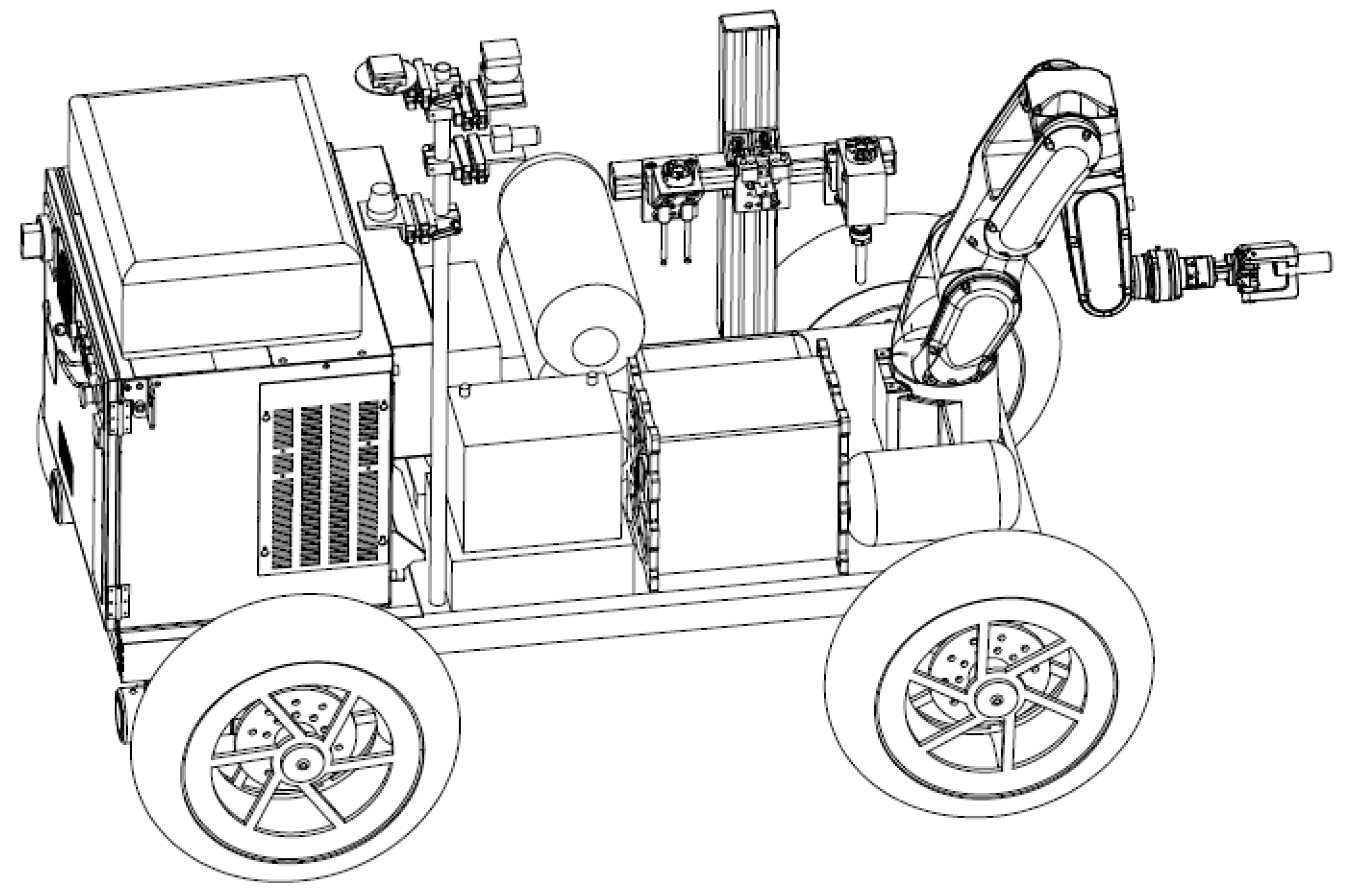
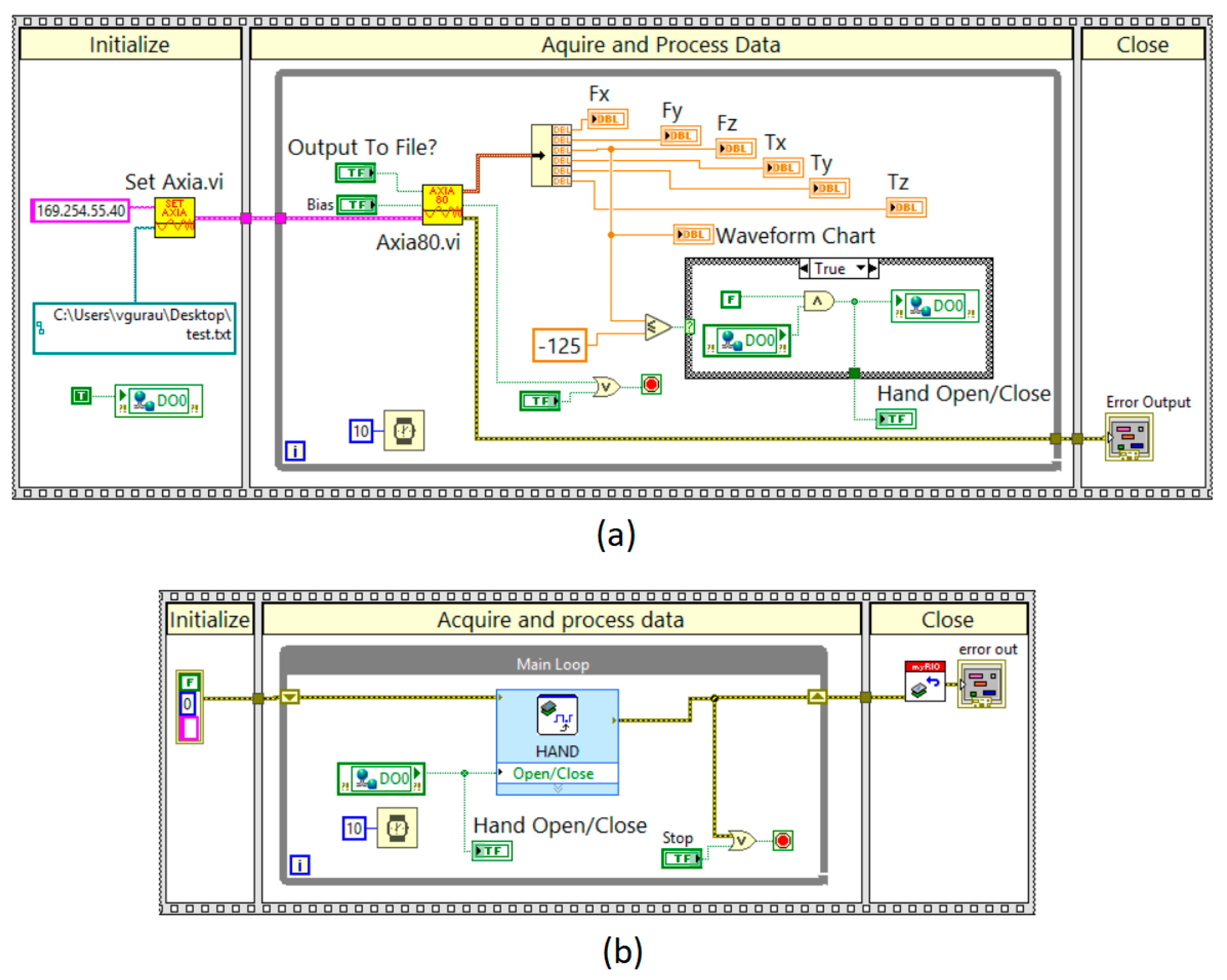
2.1. Experimental System

The robot operations were demonstrated in the laboratory using a Fanuc LR Mate 200iD robot with R-30iB controller mounted on a fixed test stand built in house (Figure 2) and equipped with a TSS tool stand (ATI Industrial Automation) for automated tool changing, a fixture for attaching a pine tree log, a compressor and safety panels.
The laboratory experiments were intended to demonstrate the capability of the industrial robot to perform the manufacturing operations required for tapping slash pine trees in conditions of inherent low positional accuracy between the robot and the pine tree on which it operates after the autonomous rover reaches the target. The laboratory experiments were performed under controlled conditions that replicated the operating conditions in the field and using real pine tree logs. The variations in the pine tree log diameter and in the relative position between the log and the industrial robot were variables controlled in the laboratory experiments. The manufacturing operations were considered successful if the robot proved capable of drilling three converging 6-inch-deep holes without jamming or breaking the cutting tool, replacing the cutting tool with a nozzle, spraying the drilled holes and the tree trunk with liquids, replacing the nozzle with a robotic hand and using it to successfully insert a tube in one of the holes and two plugs in the remaining holes. The insertions had to be snug and obtained with a sufficient force to prevent the separation or air penetration into the holes. The experiments were also used to acquire information for further process optimization and minimization of the operation cycle.
The robot tools were designed and integrated in house and consist of the following: (i) a three-fingers robotic hand (Figure 3) for picking up a PVC tube with pre-attached collection bag and two plugs and for inserting them in the boreholes; (ii) a spindle with a cutting tool (Figure 4) for drilling three converging boreholes and (iii) a two-nozzle sprayer (Figure 5) for spraying the boreholes and the tree trunk.
The robotic hand (Figure 3) consists of a DPZ+ 50-1 three-fingers centric gripper with SWA011 adapter plate (Schunk), a QC11 quick connect with tooling interface plate (ATI Industrial Automation) and three fingers fabricated in house using additive manufacturing on a Stratasys J750 Polyjet 3D printer. Two different ratio blends of VeroBlackPlusTM rigid photopolymer with a Shore hardness value of 83–86 (scale D) and Agilus30TM flexible photopolymer with a Shore hardness value of 30–35 (scale A) were used in a single printing process to fabricate the robot fingers having structured mechanical properties. A ratio of 90%/10% VeroBlackPlusTM/Agilus30TM was used to obtain the rigid fingers and a ratio of 20%/80% was used to obtain the soft fingertips. The prototype fingers thus obtained were capable to withstand the insertion forces, provided a good grasp of the tubes and prevented their slippage during the insertion process.
The drilling tool (Figure 4) consists of a 500 W, 24–50 VDC spindle attached to an aluminum angle plate, cutting tool, QC11 quick connect and tooling interface plate (ATI Industrial Automation).
The spraying tool (Figure 5) consists of two nozzles attached to an angle plate, QC11 quick connect and tooling interface plate (ATI Industrial Automation).
The robot end-of-arm is equipped with an Axia80 EtherNet force/torque sensor (ATI Industrial Automation) attached through an interface plate and a QC11 master quick connect for changing the tools. The sensor communicates with a roboRIO (National Instruments) real time target on which the LabView programs have been deployed. roboRIO communicates with the Fanuc R-30iB controller through digital input/outputs (DI/DO).

2.2. Challenges and Strategies to Address Them

While trivial to human operators, there are significant challenges when executing the operations required for tapping slash pine trees by an industrial robot. These challenges derive from using a 6-degrees of freedom (DOF) serial link manipulator with all revolute joints having a limited payload (7 kg in the case of Fanuc LR Mate 200iD) and rigid joints. The first significant challenge consists in the requirement to programmatically align the axis of insertion (for example, the axis of the tube) with the axis of the borehole and then to move the tool/tube along this axis. A second significant challenge derives from the large variations in both the shape of the pine tree trunk and in the relative position between the robot and the tree after the rover positioned itself in front of it. This implies that the position of the borehole entry point that needs to be drilled is not known a priori, and therefore needs to be determined programmatically. This is particularly important during the process of inserting the tube with collection bag or the two plugs in the boreholes, since misestimation of its position will lead to either an incomplete insertion or may result in breaking the tool. A third challenge consists in the requirement to insert the tube and plugs in the borehole with a predetermined force.
The first challenge is addressed by predefining tool frames associated to each of the three tools using the tree-point method [16] and predefining user frames oriented in the direction of the boreholes that need to be drilled, sprayed or tapped but having axes parallel to the tool frames (Figure 6). In this case, all tool frames are parallel to each other and have the Z-axis perpendicular to the robot end-of-arm (EOA), and the user frame has axes parallel to the tool frames and Z-axis aligned to the axis of the borehole. Each robot operation is programmed to move the robot EOA using the tool frame associated to the loaded tool and the user frame associated to the borehole that needs to be drilled, sprayed or tapped. This method ensures that the axis of the tool/tube is oriented along the axis of the borehole and that it is precisely inserted along it, minimizing thus the chance of being jammed.
The tool attached to the robot EOA is programmed to move along its axis, but the entry point of the borehole is not known a priori. This is particularly important during the process of inserting the tube with collection bag or the two plugs, since misestimation of its position will lead to either an incomplete insertion or may result in breaking the tool. This problem was addressed by attaching an Axia80 EtherNet force/torque sensor (ATI Industrial Automation) to the robot EOA to identify the moment when the tip of the drilling tool touches the tree surface. The position and orientation of the tool center point (TCP) relative to the robot’s world frame is recorded when a component of the measured force or torque exceeds a threshold value. Recording of the TCP pose during robot operation is possible using global position registers (PR[]) of Fanuc’s programming language. The position and orientation components of a PR[] can be recorded or changed programmatically. To identify a meaningful change in the value of any force/torque components when the drilling tool touches the tree, experiments were run using various tools and feed rates.
A typical result for the TZ component of the torque is shown in Figure 7. Note that the magnitudes of the force/torque components depend both on the type of tool and on the drilling feed rate.
Data shown in Figure 7 were acquired at a rate of 10 Hz. The threshold absolute value for the TZ component of the torque indicating the moment when the cutting tool touches the tree was further considered to be 2.5 Nm.
The overall system architecture for identifying the borehole entry point is shown in Figure 8. Axia80 sensor communicates through ethernet cable to a roboRIO real time target (National Instruments) on which the LabView program was deployed. The program scans the value of the TZ torque component and turns on a digital output (DO1) when |TZ| ≥ 2.5 Nm. DO1 of the roboRIO target is connected to DI101 of the R-30iB robot controller.
The robot subroutine for drilling runs a loop in which the TCP of the drill moves in linear motion in increments of 1 mm along the axis of the cutting tool and scans the value of DI101. The loop is repeated until the TCP touches the tree which is indicated by DI101 turning on. In this moment, the pose of the TCP (this will be the borehole entry point) is recorded in PR [17], and the drill proceeds to cut a borehole of 152 mm (6 inch). The block diagram of the subroutine is shown in Appendix A. The algorithm used to programmatically identify the starting point of the borehole and to cut it is applied to all three boreholes.
We note two alternative methods typically used in industrial robotic applications when cylindrical components must be inserted in holes during assembly processes: the use of machine vision to locate the hole entry point [17,18,19,20] or the use of an end-effector with compliance system [21,22,23,24,25,26,27] that compensates for misalignments and/or limited robot accuracy. It has been concluded that for the present application, machine vision would not identify the holes with sufficient positional accuracy due to the irregular shape of the hole contour (irregular bark texture). Furthermore, the method adopted in this work proved sufficiently robust and accurate to make the use of compliance systems unnecessary.
Using the procedures shown above for controlling the trajectory and orientation of the tools during operations and for identifying the borehole entry point enables the robot to precisely insert the tube with the collection bag, or the plugs in the boreholes. The challenge to perform these last operations consists in controlling the insertion force and avoiding an incomplete insertion or breaking the tool. This challenge is addressed by using the Axia80 EtherNet force/torque sensor to control the moment the 3-finger gripper opens to release the tube/plugs when the insertion force, FZ reaches a threshold value. The FZ component of the force was monitored during a cycle starting with the moment when the robot releases the loaded tool, loads the 3-finger gripper to the EOA, picks a tube and inserts it in the borehole (Figure 9).
The threshold value of the force was progressively increased until a strong insertion was obtained, and the possibility of the gripper to trigger open before the cycle ended was eliminated. An insertion force of −125 N was selected.
Axia80 sensor communicates the instant values of the force/torque components to roboRIO on which the LabView program was deployed. The program scans the value of FZ and turns on a digital output (DO0) when FZ ≤ −125 N. DO0 of the roboRIO target is connected to DI102 of the R-30iB robot controller (Figure 8). The LabView project for monitoring the insertion force and for triggering the output to the robot controller uses a binary shared variable, DO0, and has virtual instruments (VIs) deployed on the driver station computer for monitoring the force (Figure 10a) and on roboRIO target for triggering the output to the robot controller (Figure 10b).
The robot subroutine for insertion operations runs a loop which inserts the tube in the borehole using a linear motion in increments of 1 mm and scans the value of DI102. The loop is repeated until DI102 turns on, moment at which a robot output, RO2, opens the gripper fingers to release the tube, and the gripper withdraws. The block diagram of the robot program used for insertion operation is shown in Appendix B.

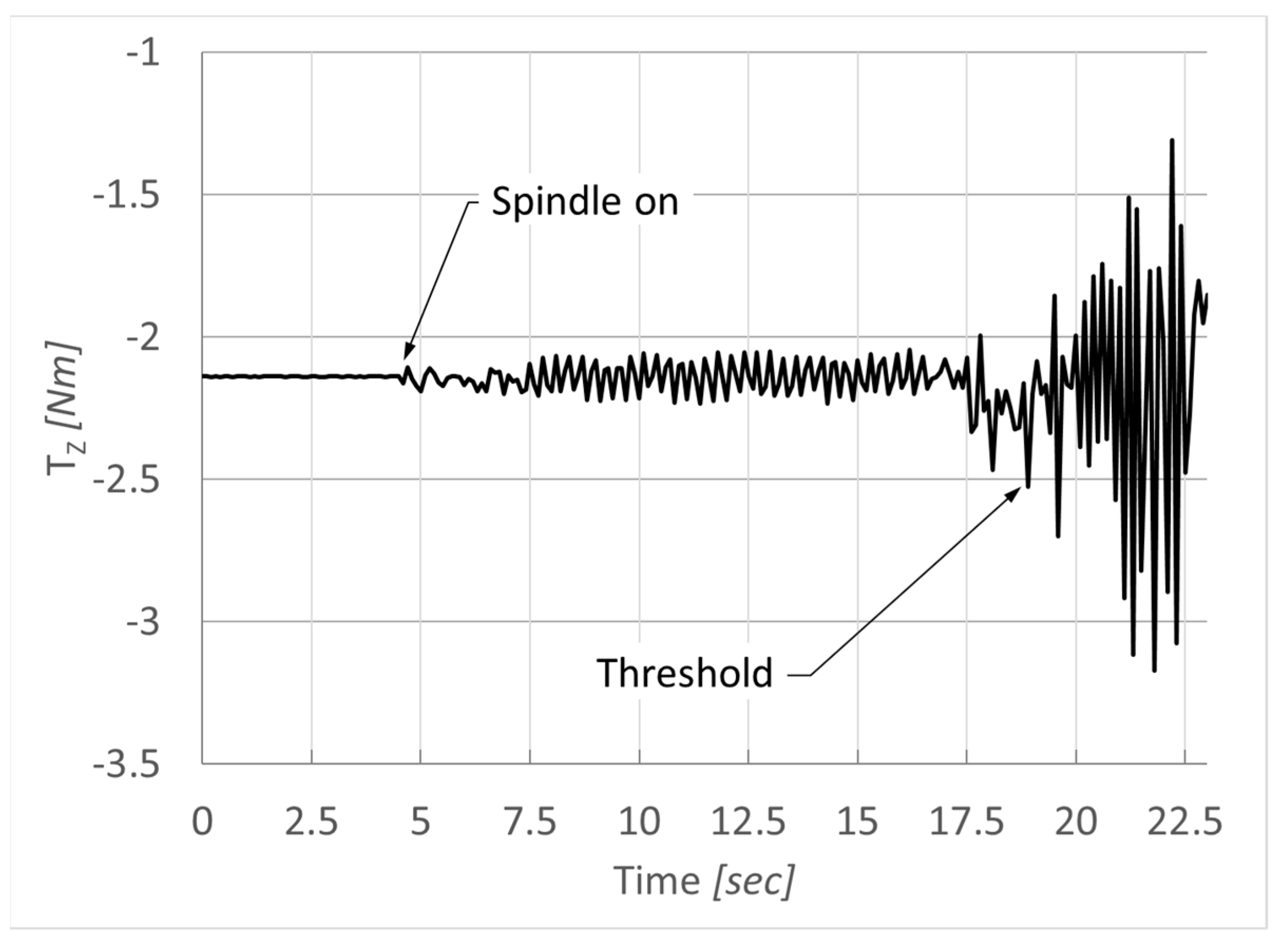
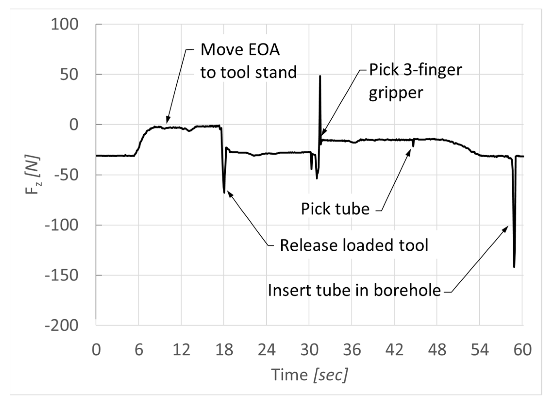
3. Results and Discussion

The strategies described in the previous section to programmatically identify the points of insertion and to control the toolpaths and the insertion force proved successful and robust. The full operation cycle for tapping slash pine trees has been successfully demonstrated. It was found that the operation cycle time is limited by vibrations of the robotic arm induced by cutting forces during the drilling operations.
To optimize the drilling operation, different cutting tools were tested for drilling 1.25-inch diameter, 6-inch-deep holes in the pine tree, including a 1.25-inch diameter auger with centering tip; a 1.25-inch diameter spade drill with centering tip; a 3/8-inch diameter, 2-flute ball mill and a 1.25-inch diameter, 4-flute end mill modified by adding a self-locking centering tip. In the latter case, a 0.2-inch diameter, ¾-inch deep hole was initially cut in the center face of the end mill, followed by tapping a ¼”-20 LH thread. A 5-axes Sodick AD 35L sinker electrical discharge machine (EDM) with graphite/Ti tools was used for both operations. A centering pin with ¼”-20 LH male thread was machined from SS 316 steel on a Haas ST10 CNC lathe and attached to the 1.25-inch end mill. When the 3/8-inch ball mill was used, the toolpath was modified by adding circular motions to obtain 1.25-inch-diameter holes. In the case of each cutting tool, the experimental drilling operations started with maximum spindle rotations per minute (RPM) and feed rate. Failures consisted in jamming the tool due to vibrations in the robot’s 4th joint that generated chatter. In case of failure, the cutting feed rate was progressively decreased to lower the cutting forces. It has been concluded that all the cutting tools with the exception of the 1.25-inch spade drill with centering tip generated excessive cutting forces that resulted in jamming the tool. The optimum cutting time for drilling one hole using the 1.25-inch spade drill was approximately 7 min, which resulted in a total operation cycle time of approximately 25 min. To further optimize the operation cycle time, either a different, stronger robot could be used, or the drilling operations could be performed by adding linear slides with cutting spindles attached on them to replace the robot drilling.
To optimize the insertion operation, experiments were performed running the robot program with progressively increased motion speed and motion termination types. Figure 11 shows the force component FZ during the tube insertion in the borehole.
When using FINE motion termination (the robot stops after each motion instruction), a limiting insertion speed was reached beyond 30 mm/s. The insertion speed could be increased by using CNT100 motion termination (the robot does not stop after each motion instruction). However, the higher the insertion speed, the more likely it is to exceed the threshold of the insertion force and the greater the danger of the gripper colliding with the tree. A robot motion speed of 100 mm/s with CNT100 motion termination was selected for the operation.

4. Conclusions

In this paper we demonstrate for the first time the feasibility of the manufacturing operations necessary for tapping slash pine trees and collecting their oleoresin for processing using the borehole method by an industrial robot. This represents a first step in the demonstration of a fully autonomous technology intended to revive the naval stores industry in southeast United States.
The paper discusses the challenges related to performing the robotic operations in conditions of large variations in the shape of the tree trunk and in the relative position between the industrial robot and the tree after the rover on which the robot is mounted reaches the destination, as well as the technical approach used to address these challenges. We present the experimental setup, the strategy and the results used to demonstrate the robotic operations. The robotic operation cycle includes loading a spindle from a tool stand and drilling three converging boreholes in the pine tree at angles that allow the flow of oleoresin due to gravity; replacing the spindle with a nozzle and spraying the boreholes with resin flow stimulating chemicals and insecticide; replacing the nozzle with a 3-fingers gripper; and picking a plastic tube with pre-attached collection bag and tapping one borehole and then picking two plugs and capping the other boreholes.
The first challenge consists in the requirement to programmatically align the axis of insertion (for example, the axis of the tube) with the axis of the borehole and then to move the tool/tube along this axis without jamming it. This challenge is addressed by predefining tool frames associated to each of the three tools and predefining user frames oriented in the direction of the boreholes that need to be drilled, sprayed or tapped but having axes parallel to the tool frames. In this case, all tool frames are parallel to each other and have the Z-axis perpendicular to the robot EOA, and the user frames have axes parallel to the tool frames and the Z-axis aligned to the axis of the borehole. This method ensures that the axis of the tool/tube is oriented along the axis of the borehole and that it is precisely inserted along it, minimizing thus the chance of being jammed. A second significant challenge derives from not knowing a priori the position of the borehole entry points and therefore from the need to determine them programmatically. This challenge was addressed by attaching a force/torque sensor to the robot EOA to identify the moment when the tip of the drilling tool touches the tree surface. The position and orientation of the TCP relative to the robot’s world frame is recorded when a component of the measured force or torque exceeds a threshold value. Recording programmatically the TCP pose during robot operation is thus possible using global position registers of Fanuc’s programming language. A third challenge consists in the requirement to insert the tube and plugs in the boreholes with a predetermined force. This challenge was addressed by using the force/torque sensor to control the moment the 3-finger gripper opens to release the tube/plugs when the insertion force reaches a threshold value.
The full operation cycle for tapping slash pine trees was successfully demonstrated in the laboratory under controlled conditions that replicate the operation conditions in the field. It was found that the operation cycle time is limited by vibrations of the robotic arm induced by cutting forces during the drilling operations. The optimum cutting time for one hole was approximately 7 min, which resulted in a total operation cycle time of approximately 25 min. To further optimize the operation cycle time, either a different, stronger robot can be used, or the drilling operations could be performed by adding linear slides with cutting spindles attached on them to replace the robot drilling. The full manufacturing operation cycle remains to be validated in field.

5. Patents

The U.S. Patent Application No. 17/331,124 (ref. [1]) which discloses the technology presented in this article has been filed with US Patent and Trademark Office on 26 May 2021.

Author Contributions

Conceptualization, V.G. and L.B.; methodology, V.G.; software, V.G. and B.R.; validation, V.G. and B.R.; formal analysis, V.G.; investigation, V.G. and B.R.; writing—original draft preparation, V.G.; writing—review and editing, D.C., L.B., B.R. and A.M.; supervision, V.G., D.C. and A.M.; project administration, V.G. and L.B.; funding acquisition, V.G. and L.B. All authors have read and agreed to the published version of the manuscript.

Funding

This research was funded by United States Department of Agriculture, grant number 2019-33610-29797.

Data Availability Statement

Acknowledgments

The authors acknowledge Frances Strickland, Charles Ginn and Jakeb Burkes for helping in performing the experiments.

Conflicts of Interest

The authors declare no conflict of interest.

Appendix A

The block diagram of the robot subroutine used to programmatically determine the pose of the borehole entry point and to cut a 6-inch borehole.
Technologies 09 00079 i001

Appendix B

The block diagram of the robot subroutine used for insertion operations.
Technologies 09 00079 i002

References

  1. Gurau, V.; Busby, L. Autonomous Robotic Forest Rover for Automated Resin Collection. U.S. Patent Application No. 17/331,124, 26 May 2021. [Google Scholar]
  2. Visser, R.; Obi, O.F. Automation and Robotics in Forest Harvesting Operations: Identifying Near-Term Opportunities. Croat. J. For. Eng. 2021, 42, 12–24. [Google Scholar] [CrossRef]
  3. Parker, R.; Bayne, K.; Clinton, P.W. Robotics in Forestry. N. Z. J. For. 2016, 60, 8–14. [Google Scholar]
  4. Fue, K.G.; Porter, W.M.; Barnes, E.M.; Rains, G.C. An Extensive Review of Mobile Agricultural Robotics for Field Operations: Focus on Cotton Harvesting. AgriEnginnering 2020, 2, 150–174. [Google Scholar] [CrossRef] [Green Version]
  5. Underwood, J.; Wendel, A.; Schofield, B.; McMurray, L.; Kimber, R. Efficient in-field plant phenomics for row-crops with an autonomous ground vehicle. J. Field Robot. 2017, 34, 1061–1083. [Google Scholar] [CrossRef]
  6. Kurita, H.; Iida, M.; Cho, W.; Suguri, M. Rice Autonomous Harvesting: Operation Framework. J. Field Robot. 2017, 34, 1084–1099. [Google Scholar] [CrossRef]
  7. Botterill, T.; Paulin, S.; Green, R.; Williams, S.; Lin, J.; Saxton, V.; Mills, S.; Chen, X.; Corbett-Davies, S. A Robot System for Pruning Grape Vines. J. Field Robot. 2017, 34, 1100–1122. [Google Scholar] [CrossRef]
  8. Bac, C.W.; Hemming, J.; van Tuijl, B.A.J.; Barth, R.; Wais, E.; van Henten, E.J. Performance Evaluation of a Harvesting Robot for Sweet Pepper. J. Field Robot. 2017, 34, 1123–1139. [Google Scholar] [CrossRef]
  9. Bawden, O.; Kulk, J.; Russell, R.; McCool, C.; English, A.; Dayoub, F.; Lehnert, C.; Perez, T. Robot for weed species plant-specific management. J. Field Robot. 2017, 34, 1179–1199. [Google Scholar] [CrossRef]
  10. Cunningham, A. Chapter 1: Pine resin tapping techniques used around the world. In Pine Resin: Biology, Chemistry and Applications; Fett-Neto, A.G., Rodrigues-Corrêa, K.C.d.S., Eds.; Research Signpost: Kerala, India, 2012; ISBN 978-81-308-0493-4. [Google Scholar]
  11. Lauture, M.J. Reinvigorating Oleoresin Collection in the Southeast USA: Evaluation of Chemical Inducers, Stand Management, Tree Characteristics, and Genetics. Doctoral Dissertation, University of Florida, Gainesville, FL, USA, 2017. [Google Scholar]
  12. Rodrigues-Corrêa, K.C.d.S.; de Lima, J.C.; Fett-Neto, A.G. Oleoresins from pine: Production and industrial uses. In Natural Products; Ramawat, K.G., Merillon, J.M., Eds.; Springer: Berlin, Germany, 2013; ISBN 978-3-642-22145-3. [Google Scholar]
  13. Hadiyane, A.; Sulistyawati, E.; Asharina, W.P.; Dungani, R. A Study on Production of Resin from Pinus merkusii Jungh. Et De Vriese in the Bosscha Observatory Area, West Java-Indonesia. Asian J. Plant Sci. 2015, 14, 89–93. [Google Scholar] [CrossRef] [Green Version]
  14. Busby, L.K. A Dissolvable Collection System for Turpentine Production. International Patent Application No. WO 2018/035490 Al, 2 February 2018. [Google Scholar]
  15. Rubber Tapping Robots Put to Trial Operation. Available online: https://www.youtube.com/watch?v=heSUQXHnIho (accessed on 1 August 2021).
  16. FANUC America Corporation. Handling Tool Operations & Programming Student Manual; Fanuc Robotics: Rochester, MI, USA, 2016. [Google Scholar]
  17. Chen, C.P.; Huang, Z. Blasting Hole Recognition and Location Based on Machine Vision. Appl. Mech. Mater. 2015, 733, 718–721. [Google Scholar] [CrossRef]
  18. Davies, E.R. Chapter 13: Hole detection. In Machine Vision: Theory, Algorithms, Practicalities, 3rd ed.; Elsevier: Boston, MA, USA, 2004; ISBN 9780122060939. [Google Scholar]
  19. Yachida, M.; Tsuji, S. A Versatile Machine Vision System for Complex Industrial Parts. IEEE Trans. Comput. 1977, C-26, 882–894. [Google Scholar] [CrossRef]
  20. Davits, E.R.; Barker, S.P. An analysis of hole detection schemes. In Proceedings of the British Machine Conference; Sleigh, A., Ed.; BMVA Press: Surrey, UK, 1990; pp. 51.1–51.6. [Google Scholar] [CrossRef] [Green Version]
  21. Rice, J.J.; Schimmels, J.M. Passive Compliance Control of Redundant Serial Manipulators. J. Mech. Robot. 2018, 10, 044507. [Google Scholar] [CrossRef] [Green Version]
  22. Williams, M.; Tignor, K.; Sigler, L.; Rajagopal, C.; Gurau, V. Robotic Arm for Automated Assembly of Proton Exchange Membrane Fuel Cell Stacks. J. Fuel Cell Sci. Technol. 2014, 11, 054501. [Google Scholar] [CrossRef]
  23. Gurau, V.; Armstrong-Koch, T. Further Improvements of an End-Effector for Robotic Assembly of Polymer Electrolyte Membrane Fuel Cells. Energies 2015, 8, 9452–9463. [Google Scholar] [CrossRef] [Green Version]
  24. Wang, W.; Loh, R.N.K.; Gu, E.Y. Passive Compliance Versus Active Compliance in Robot-Based Automated Assembly Systems. Ind. Robot. 1998, 25, 48–57. [Google Scholar] [CrossRef]
  25. Gurau, V.; Fowler, D.; Cox, D. Chapter 3: Robotic technologies for proton exchange membrane fuel cell assembly. In Proton Exchange Membrane Fuel Cell; Taner, T., Ed.; IntechOpen: London, UK, 2018. [Google Scholar] [CrossRef] [Green Version]
  26. Ang, M.H., Jr.; Wang, W.; Loh, R.N.K.; Low, T.S. Passive Compliance from Robot Limbs and its Usefulness in Robotic Automation. J. Intell. Robot. Syst. 1997, 20, 1–21. [Google Scholar] [CrossRef]
  27. Fowler, D.; Gurau, V.; Cox, D. Bridging the Gap between Automated Manufacturing of Fuel Cell Components and Robotic Assembly of Fuel Cell Stacks. Energies 2019, 12, 3604. [Google Scholar] [CrossRef] [Green Version]
Figure 1. Conceptual model of the autonomous robotic forest rover for automated pine resin collection.
Technologies 09 00079 g001
Figure 2. Laboratory test stand for demonstration of robot operations.
Technologies 09 00079 g002
Figure 3. (a) Robot hand components: (1) end-of-arm-sensor interface; (2) Axia80 EtherNet force/torque sensor; (3) QC11 master quick connect; (4) QC11 tool side quick connect; (5) SWA011 adapter plate; (6) DPZ+ 50-1 three-fingers centric gripper; (7) tooling interface plate; (8) fingers; (b) The robot hand during insertion of a plug in a borehole.
Technologies 09 00079 g003
Figure 4. Drilling tool during a borehole drilling operation.
Technologies 09 00079 g004
Figure 5. Two-nozzles spraying tool during spraying operation.
Technologies 09 00079 g005
Figure 6. Tool frames and user frames with parallel axes and oriented in the direction of drilling/spraying or inserting.
Technologies 09 00079 g006
Figure 7. Measured TZ component of the torque showing the moment when the cutting tool touched the tree.
Technologies 09 00079 g007
Figure 8. Overall system architecture for identifying the pose of the TCP when the drilling tool touches the tree (borehole entry point).
Technologies 09 00079 g008
Figure 9. Measured Fz component of the force during an insertion cycle.
Technologies 09 00079 g009
Figure 10. LabView VIs for monitoring the insertion force and for triggering the output to the robot controller; (a) VI on the driver station; (b) VI on roboRIO.
Technologies 09 00079 g010
Figure 11. FZ component of the force during insertion operations using various robot motion speeds and motion termination types.
Technologies 09 00079 g011
Publisher’s Note: MDPI stays neutral with regard to jurisdictional claims in published maps and institutional affiliations.

