Article

Challenges of Using the L-Band and S-Band for Direct-to-Cellular Satellite 5G-6G NTN Systems

by
Alexander Pastukh
1,*,
Valery Tikhvinskiy
1,2,
Svetlana Dymkova
3,4 and
Oleg Varlamov
3,4,*
1
Radio Research and Development Institute, 105064 Moscow, Russia
2
International Information Technologies University (IITU), Almaty 050000, Kazakhstan
3
Institute of Radio and Information Systems (IRIS), 1010 Vienna, Austria
4
Moscow Technical University of Communication and Informatics, 111024 Moscow, Russia
*
Authors to whom correspondence should be addressed.
Technologies 2023, 11(4), 110; https://doi.org/10.3390/technologies11040110
Submission received: 6 June 2023 / Revised: 5 August 2023 / Accepted: 8 August 2023 / Published: 10 August 2023
(This article belongs to the Special Issue Intelligent Reflecting Surfaces for 5G and Beyond)

Abstract

:
This article presents a comprehensive study of the potential utilization of the L-band and S-band frequency ranges for satellite non-terrestrial network (NTN) technologies. This study encompasses an interference analysis in the S-band, investigating the coexistence of NTN satellite systems with mobile satellite networks such as Omnispace and Lyra, and an interference analysis in the L-band between NTN satellites and the mobile satellite network Inmarsat. This study simulates an NTN satellite network with typical characteristics defined by 3GPP and ITU-R for the n255 and n256 bands. Furthermore, it provides calculations illustrating the signal-to-noise ratio degradation of low-Earth-orbit (LEO), medium-Earth-orbit (MEO), and geostationary-Earth-orbit (GEO) satellite networks operating in the L-band and S-band when exposed to interference from NTN satellites.

1. Introduction

The concept of integrating satellite technology with cellular mobile networks has been around for a long time. In the mid-1990s, the International Telecommunications Union (ITU) introduced the IMT-2000 (International Mobile Telecommunications 2000) initiative with the goal of achieving global wireless access in the 21st century. This initiative led to the establishment of the Third-Generation Partnership Project (3GPP). Several standards were developed, such as CDMA-2000 (Code Division Multiple Access 2000), UMTS (Universal Mobile Telecommunications System), and TD-CDMA (Time Division-Code Division Multiple Access), collectively known as 3G. IMT-2000 was intended to include both terrestrial and satellite components, and the ITU-R (ITU Radiocommunication Sector) developed various reports on the satellite aspect of IMT-2000 [1]. However, due to the high costs involved and a lack of sufficient user demand, the idea of implementing a satellite-based 3G network was not pursued. Today, an increasing number of LTE and 5G users have begun to prioritize ubiquitous connectivity rather than increased data rates [2,3]. As many individuals enjoy traveling to remote areas with no existing connectivity, satellite technology has become an increasingly convenient solution to provide such services. Consequently, the development of direct-to-cellular 5G satellite NTN (non-terrestrial networks) has become a prominent and essential objective. Furthermore, it is anticipated that satellites will become integral part of future 6G technology, making it imperative to establish suitable conditions for the development of 5G-6G satellite networks. One of the most challenging issues in achieving this goal is securing a sufficient amount of spectrum for such networks.
Currently, there are two approaches to spectrum assessment for satellite 5G-6G networks [4]. The first approach involves the convergence of the satellite and terrestrial components of 5G-6G within the frequency bands already designated for terrestrial GSM, 3G, LTE and 5G [5]. This approach has been adopted by companies like Lynk and AST SpaceMobile, which utilize the 700 MHz and 800 MHz frequency bands. Additionally, SpaceX, in partnership with T-Mobile, announced plans to use the 1910–1915/1990–1995 MHz frequency bands for their next generation of Starlink satellites, which will provide direct-to-cellular services. The FCC even released a regulatory framework document describing how to regulate the work of direct-to-cellular satellite services within terrestrial frequency bands [6].
The second approach is to utilize the spectrum allocated for mobile satellite services defined by 3GPP explicitly for non-terrestrial network (NTN) technologies. Currently, 3GPP is considering a 5G satellite (NTN) and has specified non-terrestrial frequency ranges, the n255 band and n256 band. Table 1 provides frequency number details for these two bands.
These frequency ranges offer advantages such as lower propagation losses and compatibility with legacy communications, which means existing components can be utilized. However, a notable drawback is the well-known spectrum crunch as these bands are already heavily occupied, restricting the usable bandwidth. The maximum overall bandwidth anticipated is up to 40 MHz. To maintain compatibility with 5G/6G, the NTN will adopt the bandwidth part (BWP) methodology. Each user equipment (UE) can be configured with one or multiple BWPs, and the UE need not be concerned about the SAN (satellite access node) channel bandwidth. Flexibility is possible via the segmentation of the overall SAN channel bandwidth using different numerologies. The common definitions for channel bandwidth, transmission bandwidth configuration, minimum guard band, and RB alignment in TS 38.104 and TS 38.101-1 can be reused for an NTN satellite system; however, RAN4 analysis and simulation results demonstrated that it is not feasible to implement the Rel.17 NTN for the SCS of UL signals lower than 60 kHz (FR1) since the guard period is insufficient period due to the estimated timing error budget [7].
At first glance, the second approach appears to be more convenient and logical, as 3GPP has been defining technical specifications for generations of cellular technology for decades, and utilizing satellite mobile service frequencies seems like the most plausible option. However, this approach has several notable flaws, one of which is spectrum assessment.
Given that satellite coexistence is a global issue, frequency coordination for satellite networks conducted within ITU-R is a complex and time-consuming procedure. The frequency bands defined by 3GPP for NTN technologies are already in use by several satellite operators providing mobile communication services, including voice, data, and Internet of Things services. It should be noted that some of these services are critically important for communications. The future NTN satellite 5G-6G networks would require the development of LEO megaconstellations which will have very high activity factors and consequently significantly increase the interference level in these bands for the existing networks. Therefore, it would be challenging for countries wishing to use the n255 and n256 bands to meet the coordination requirements and gain access to this spectrum.
In our study, we present an interference analysis using simulated 5G satellite networks with typical characteristics developed by 3GPP and ITU-R, as well as several satellite networks operating in the n255 and n256 bands, such as Inmarsat, Echostar, and Omnispace. The intention of this study is to highlight the compatibility challenges that will be faced by those seeking to utilize the n255 and n256 bands for 5G-6G satellite technologies.

2. Literature Review

The current state of research on the topic of this article reveals a significant gap in the understanding of the aspects of co-existence with other satellite systems operating in the n255 and n256 bands. Currently, there is a lack of publicly available articles or reports that adequately address this issue. This scarcity of research on co-existence and regulatory issues in the specific frequency bands is a notable gap in the existing literature. Some insights into co-existence and regulatory matters can be found in the works of some authors, for example, in [8], where the possibility of sharing the spectrum between terrestrial 5G and an NTN segment of 5G is described. The 3GPP TR 38.863 report titled “non-Terrestrial networks (NTN) related RF and co-existence aspects” primarily focuses on frequency allocations based on the ITU-R Radio Regulations (RR) [9]. One of the published articles describes the compatibility between satellite and terrestrial segments of 5G in the adjacent channel [10], while in [11], a methodology simulating compatibility between NGSO (Non-Geostationary Satellite Orbit) and GSO (Geostationary Satellite Orbit) systems, which is quite important when considering co-existence studies between NTN and GSO systems, is described. However, the above-mentioned works do not encompass any simulations involving other satellite systems already operating in the n255 and n256 bands. This omission highlights the lack of comprehensive research in this critical area.
This issue is anticipated to be thoroughly examined during the ITU-R’s coordination process, in which operators will seek to file NTN networks in these bands. The successful filing of NTN networks would necessitate comprehensive studies to demonstrate co-existence compliance with existing satellite networks. Consequently, the lack of studies on the aspects of co-existence with the incumbent satellite systems operating in the n255 and n256 bands shows the need for further research and investigation on that topic, which would aid the satellite operators that seek to implement NTN networks and aim to understand the most suitable spectrum for this purpose.

3. Materials and Methods

In 2021, 3GPP released a technical report, TR 38.821, titled “Solutions for NR to Support Non-Terrestrial Networks (NTN)”. This report provides the necessary parameters for simulating NTN networks that offer 5G services [12]. Its main objective is to define the essential features and adaptations required for the New Radio (NR) protocol to operate in non-terrestrial networks, with a particular focus on satellite access. With the release of 3GPP Release 17, non-terrestrial networks were officially incorporated into the 3GPP ecosystem. The primary NTN bands defined for this release are band 255 (UL: 1626.5–1660.5 MHz/DL: 1525–1559 MHz), and band 256 (UL: 1980–2010 MHz/DL: 2170–2200 MHz). The specifications of Release 17 aim to support New Radio (NR)-based satellite access deployed in FR1 bands, which operate below 6 GHz. This enables the provision of global service continuity for handheld devices. Additionally, it will also support NB-IoT- and eMTC-based satellite access to cater to use cases in sectors such as agriculture, transport, and logistics [13]. 
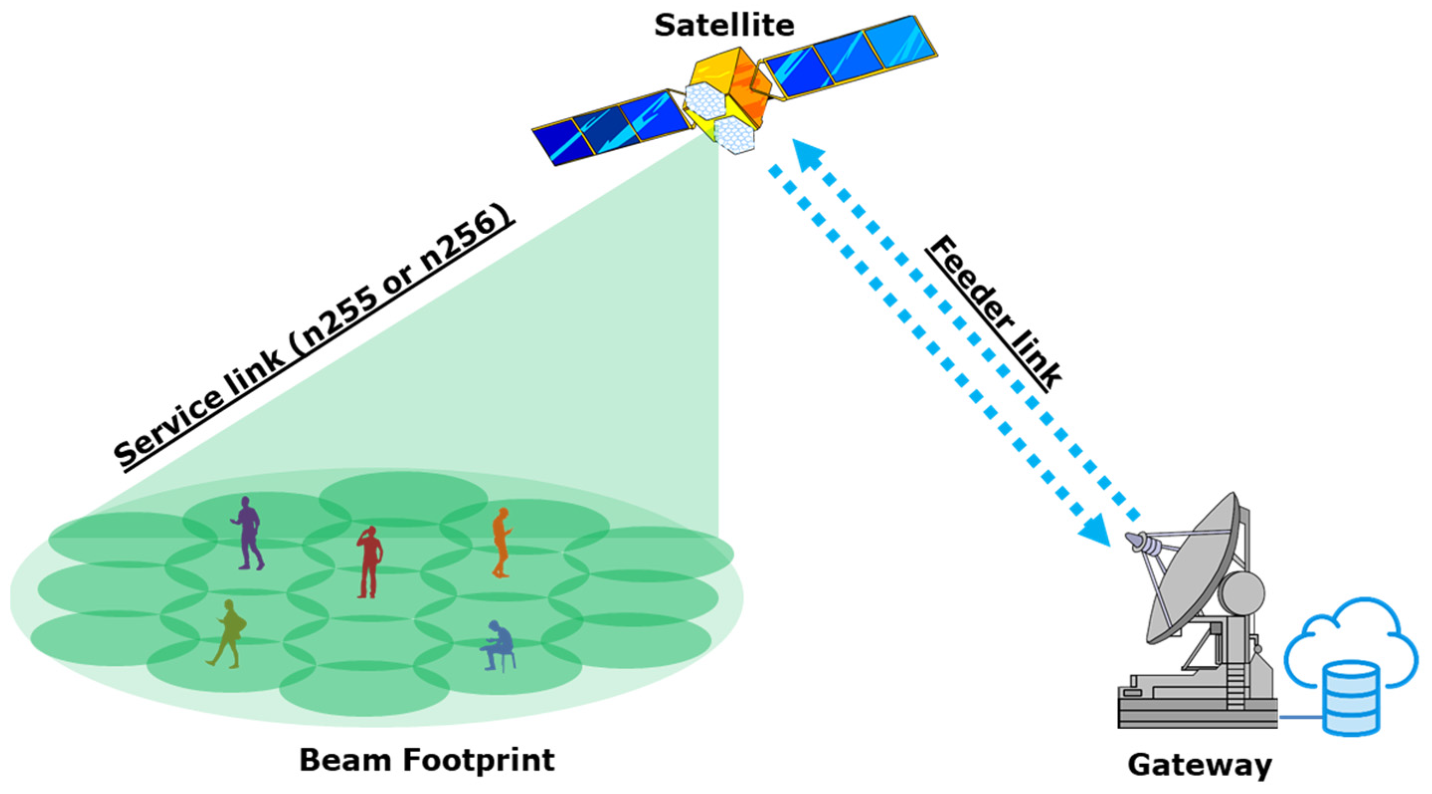
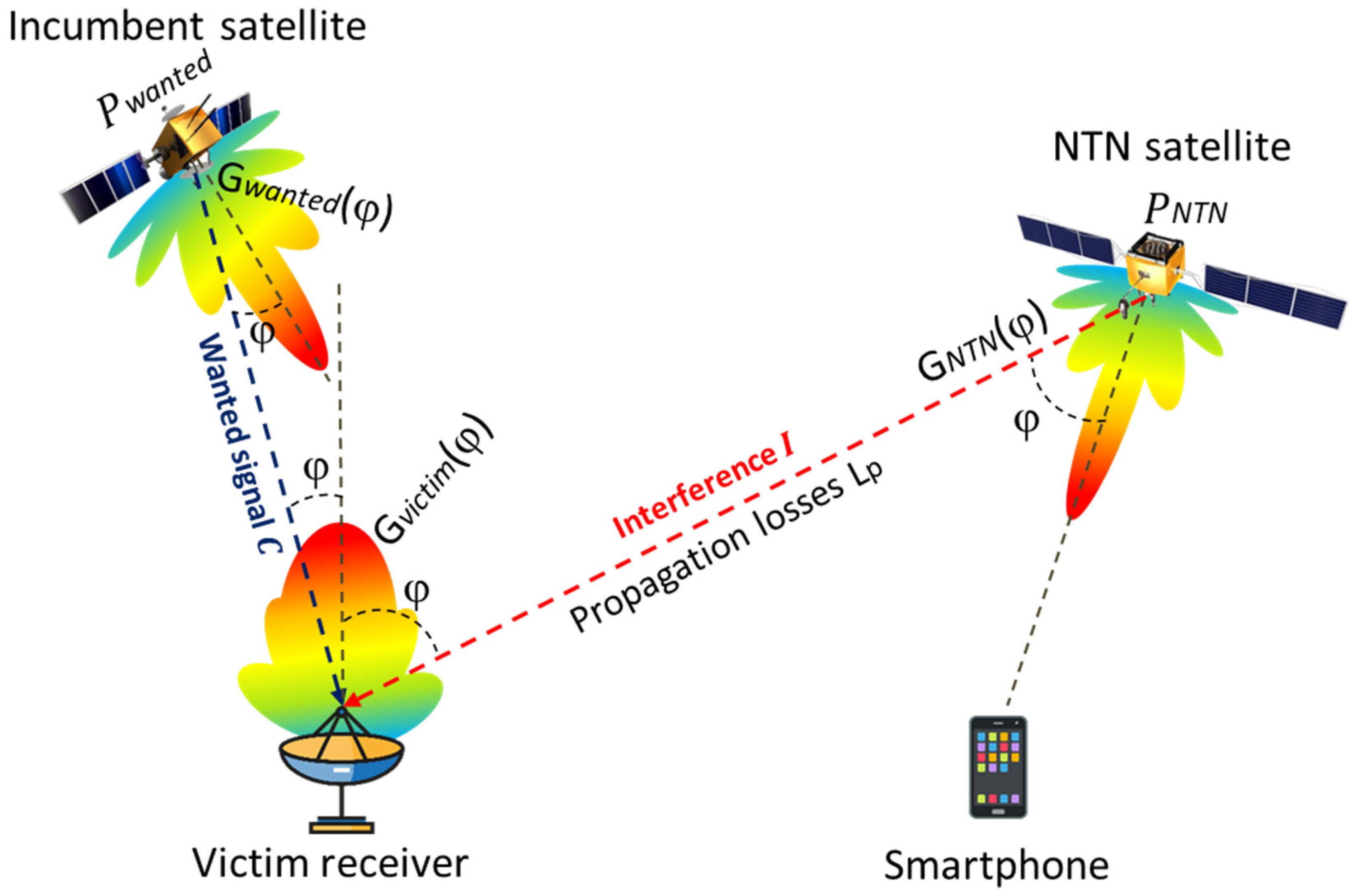
Figure 1 illustrates a typical scenario depicting the direct-to-cellular NTN composition.
In 2022, ITU-R published a report called ITU-R M.2514 [14], which is titled “Vision, Requirements, and Evaluation Guidelines for Satellite Radio Interface(s) of IMT-2020”. The purpose of this report is to establish a vision and define the requirements and evaluation guidelines for the satellite component of IMT-2020. It covers various aspects such as use cases, application scenarios, capabilities, and system requirements. The characteristics outlined in this report align closely with those provided in TR 38.821 by 3GPP.
The report includes baseline configuration parameters that are essential for analyzing and simulating candidate satellite radio interfaces for 5G. These characteristics provide the necessary parameters for simulating link budgets and traffic models and conducting an interference analysis. As our focus is on an interference analysis in which the candidate satellite 5G NTN system acts as a source of interference, we will only use the relevant characteristics from the table that pertain to simulating 5G satellite interferences. Table 2 in Report ITU-R M.2514 presents these parameters.
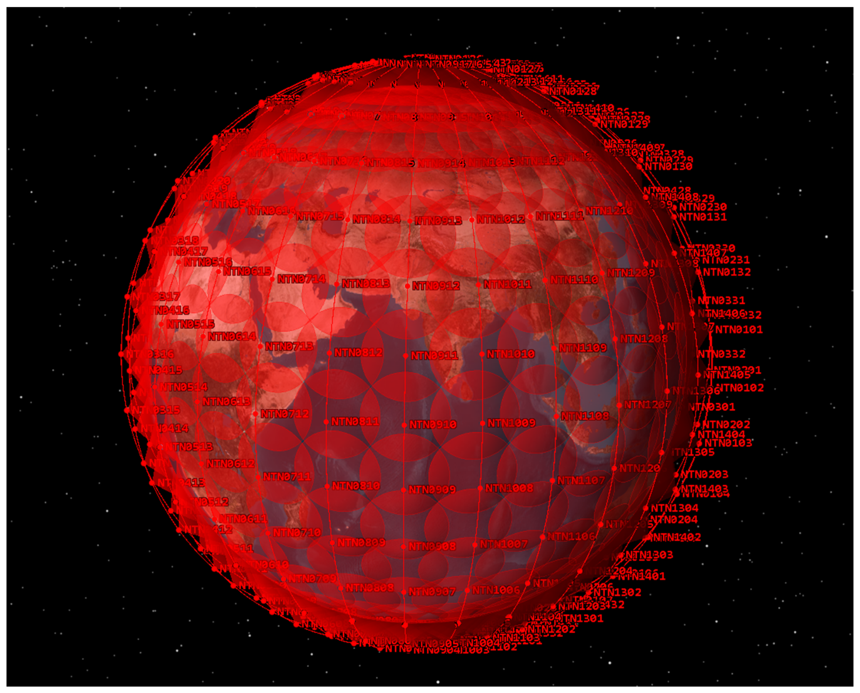
It is worth noting that 3GPP TR 38.821 contains nearly identical parameters. While these parameters are specified for the S-band, it is mentioned that the carrier frequency of 2 GHz is merely an indicative value. Therefore, in our study, we assume that the characteristics for the L-band will be similar. Considering that the propagation difference between the downlink of the n255 and n256 bands is approximately 3 dB, we have adjusted the downlink satellite EIRP (equivalent isotropic radiated power) for the L-band accordingly. The orbital parameters, as well as the number of satellites, are not specified in the typical characteristics because they will largely depend on the types of services that will be provided by the NTN and coverage requirements. In our study, we considered a constellation of 448 satellites with 89 degrees of inclination; it should be noted that for contiguous coverage in practice, there could be a much greater number of satellites, so from the standpoint of protecting incumbent systems from the NTN interference our assumption may be considered optimistic. Orbital characteristics are presented below in Table 3.
STK software was used for the simulations, and the satellites were simulated using the orbital parameters from Table 2 and the transmitting parameters from Table 1. Figure 2 presents simulation of the typical NTN constellation.
Based on Table 1, the satellite’s service area is comprised of a hexagonal shape with a minimum of 19 spot beams. In our study, we simulated 19 spot beams for each satellite. However, it is important to note that to prevent interference between adjacent beams, spot beams are usually divided by frequency. Therefore, in our study, we assumed that only four randomly selected beams per satellite were sources of interference. 
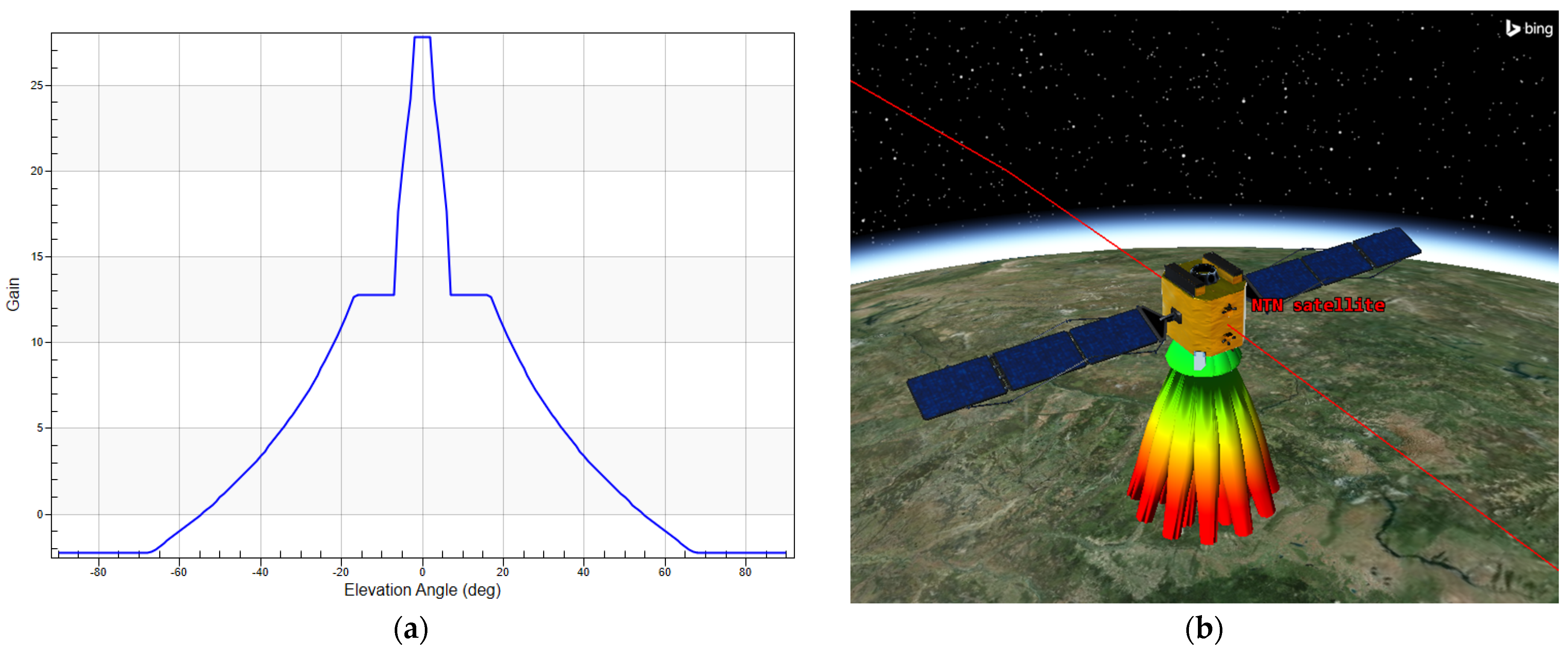
Figure 3 illustrates the approximation of the antenna pattern of a single beam and provides a model of 19 beams antenna pattern. The 3GPP and ITU-R reports do not provide any particular antenna pattern for a beam; therefore, for a beam antenna pattern recommendation, we turned to the ITU-R S.1528 [15], since it is the most commonly used pattern for NGSO mobile satellite simulations below 30 GHz. To implement the antenna in accordance with the approximations provided in the ITU-R Recommendation S.1528 and characteristics in Table 2, an antenna size between 2 and 2.5 m would be required; it should be noted that this size is based on theoretical expressions, assuming an efficiency between 0.55 and 0.65, and in practice, the size of the antenna may vary slightly at the production stage. The size of the antenna is related with the frequency and maximum gain by the following expression:
G m a x = η π D f c 2
where Gmax represents the maximum gain of the antenna, η represents antenna efficiency, D represents the antenna diameter, f represents frequency and c represents the speed of light.
Figure 3. Antenna pattern of NTN simulated satellite beam: (a) one-beam pattern; (b) 3D visualization of multiple beams.
Technologies 11 00110 g003
As previously mentioned, the uplink for the n255 and n256 bands operates in the frequency ranges of 1626.5–1660.5 MHz and 1980–2010 MHz, respectively. The corresponding downlink operates in the frequency ranges of 1525–1559 MHz and 2170–2200 MHz, respectively. In direct-to-cellular NTN communications, typical smartphones will be utilized. Given that smartphones operate at a maximum power of 200 mW, the interference they cause in the uplink portions of the n255 and n256 bands to the satellite receivers of existing systems is expected to be insignificant. However, in the downlink portions, interference from NTN satellites to the ground and the aerial receivers of the incumbent satellite systems is possible. In particular, interference levels may be significantly higher when the main lobe of the NTN satellite overlaps with the main lobe of the receiving antenna’s pattern gain of the incumbent services.
The study considers several incumbent satellites networks in the n255 and n256 bands as the interference receptors from the possible future 5G-6G NTN systems. The frequency bands 1525–1559 MHz and 1626.5–1660.5 MHz (n255 band) are split between several operators, according to the GSO/MSS L-band multilateral meeting memorandum of understanding. There are several operators that are part of that memorandum, such as Inmarsat, Thuraya, and others [16]. In our study, we considered the Inmarsat system a victim network, which is a GSO satellite system. Inmarsat offers a range of services that can be broadly categorized into maritime, aeronautical, and land applications. Maritime users rely on Inmarsat for the GMDSS satcom service, which plays a crucial role in distress alerts, the transmission and reception of maritime safety information, and vessel tracking [17].
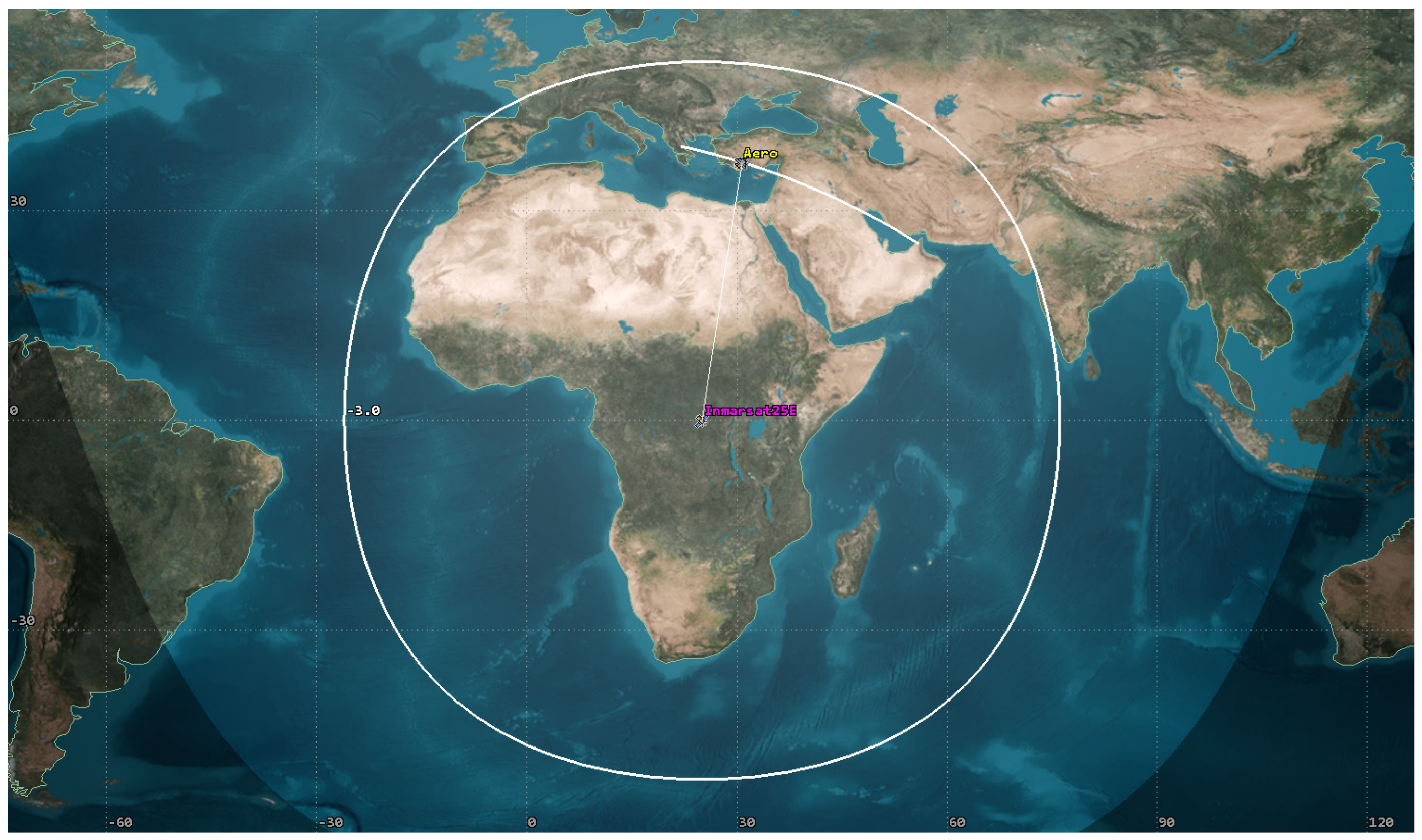
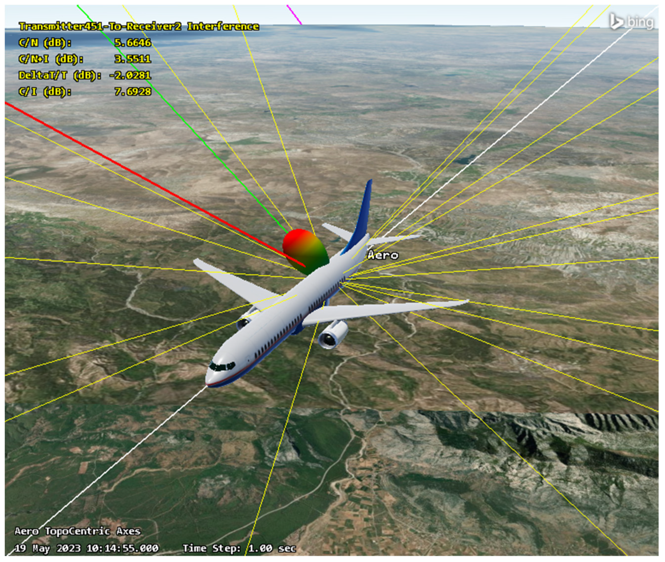
In addition, many airlines utilize Inmarsat’s L-band service to support the AMS(R)S service, particularly in oceanic regions where satellite communication is necessary beyond the reach of VHF terrestrial communications. L-band satellite communications are also increasingly adopted for aircraft communication over land to alleviate congestion on VHF frequencies. In this study, we analyzed interference in the downlink of the 25E Inmarsat satellite for Aero terminals that are installed in the aircrafts. Typical characteristics were obtained from the ITU-R filing information and are summarized in Table 4.
For the Inmarsat satellite transmitter, an antenna pattern based on the ITU-R S.672 Recommendation was used since it is the most commonly used pattern for simulating GEO satellites [18]. The simulation of the Inmarsat link with an Aero satellite is illustrated below, in Figure 4. In the figure, 3 dB is shown. In our study, we considered the INM-AERO (H) C-21 terminal, and the aircraft was moving within the 3 dB contour.
For the n256 band, two incumbent NGSO satellite systems were considered; the first one was an MEO satellite system, Omnispace. Initially, this system was part of ICO Global Communications, which had intentions to launch 12 satellites that were designed to provide voice communication services. In 2001, the first satellite was successfully launched; later, in 2004, the company filed for bankruptcy, and later, in 2012, Omnispace acquired the ICO-F2 MEO satellite from ICO Global Communications. The Boeing-built satellite was renamed Omnispace-F2 and currently is operating in the S-band, providing mobile communications and data/Internet services and supporting 4500 simultaneous calls. Table 5 provides link characteristics of the Omnispace F2 satellite for several types of mobile Earth stations (MESs).
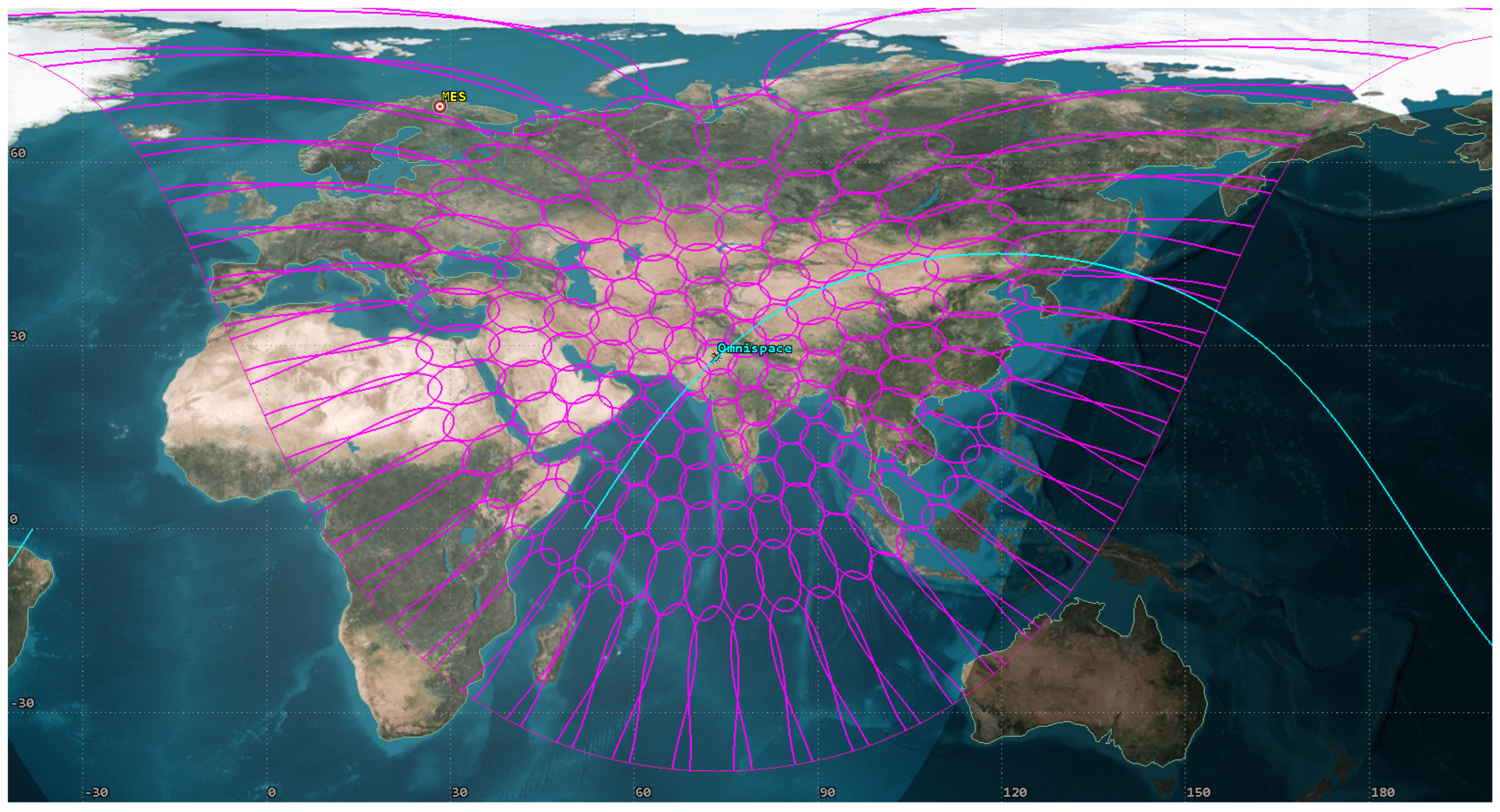
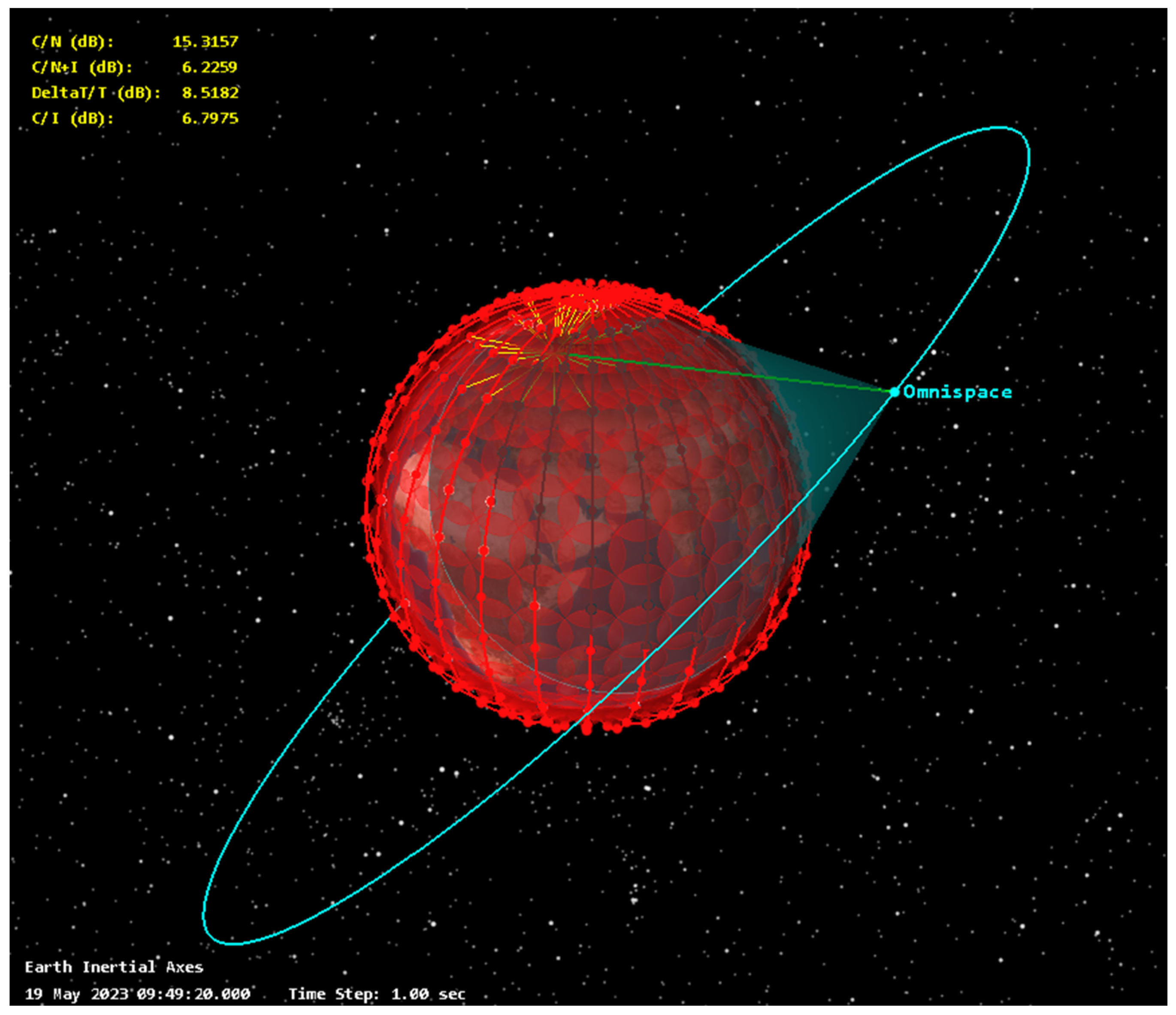
The satellite is located in the MEO orbit at an altitude of 10,500 km with a 45-degree inclination, and the S-band part consists of 163 spot beams. Below, Figure 5 provides a simulation of the wanted Omnispace link where MES-1 is considered.In this figure, pink lines represent each spot beam of the Omnispace satellite. For our study, the MES was placed in a northern region because Omnispace is primarily utilized in the Far North, where the connectivity is especially needed for unserved areas.
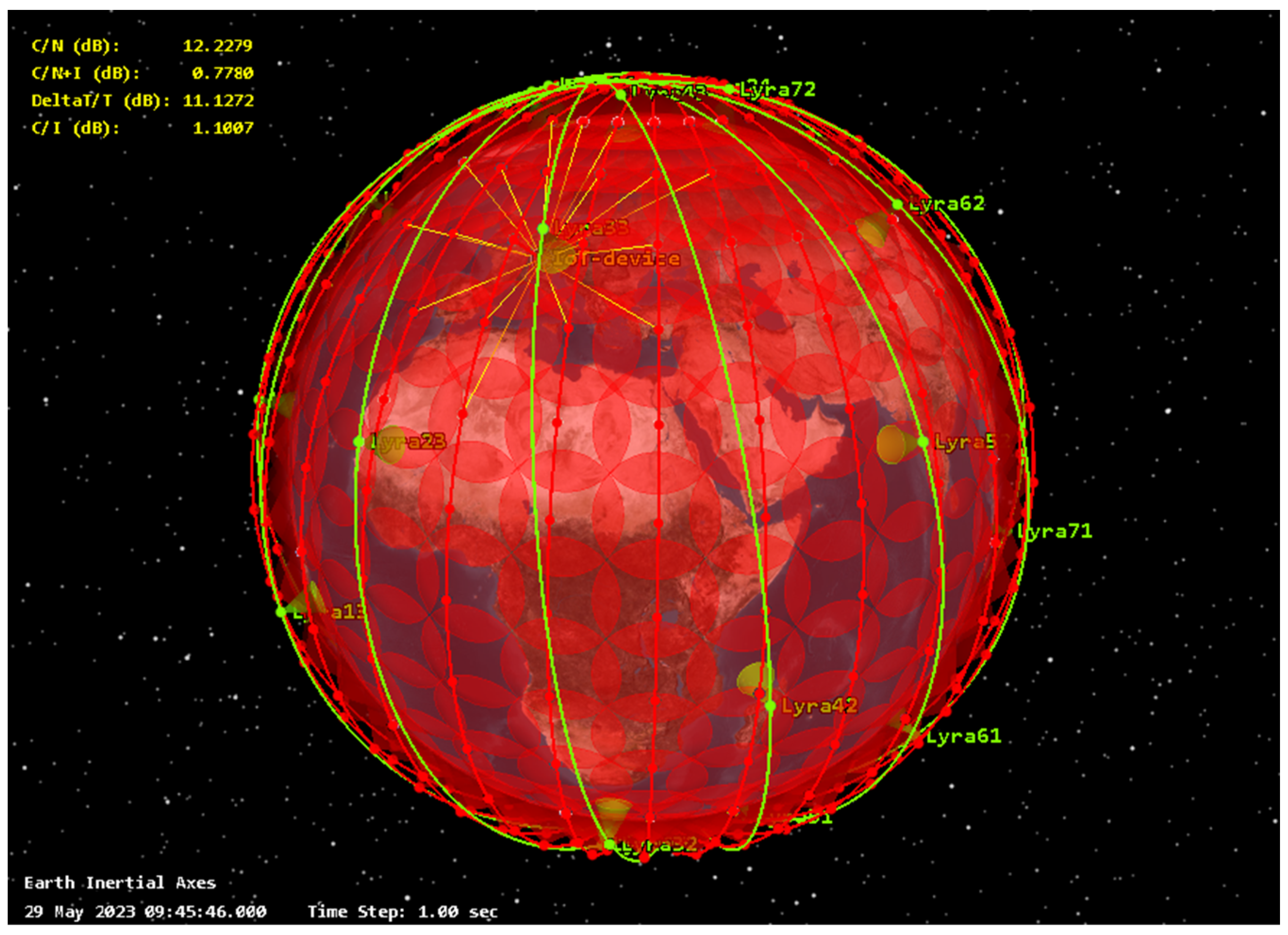
Another incumbent satellite system considered in this study is Lyra, a low-Earth-orbit (LEO) system that is intended to be implemented by EchoStar for IoT services. Originally known as Sirion, Lyra was previously owned by Helios Wire. In 2019, EchoStar Global, LLC, acquired the Helios Wire Corporation, and the Lyra satellite constellation will be based on the existing Sirion-1 network, which was previously filed with ITU-R. As of now, three satellites have been successfully launched: EG-1 (Tyvak-0172), EG-2 (Tyvak-0171), and EG-3 (Tyvak-0173), which were launched between 2020 and 2021. Table 6 provides the characteristics of Lyra satellite links based on the Sirion-1 ITU-R filing.
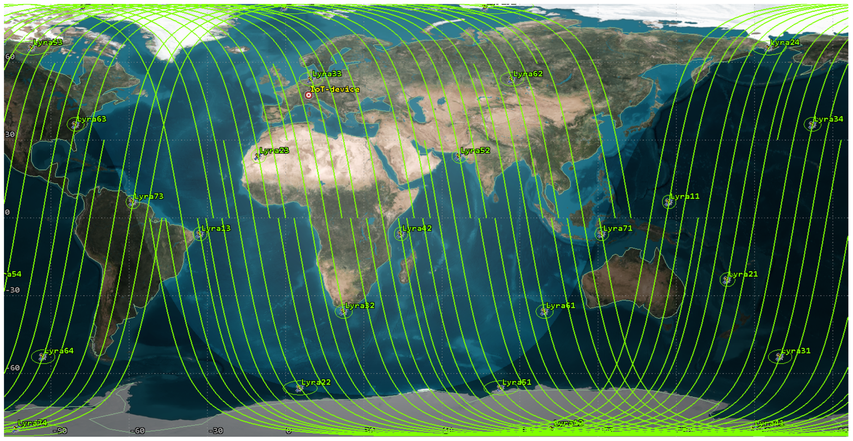
The Lyra satellite system will comprise twenty-eight satellites distributed across seven orbital planes, with four satellites per plane. These satellites will operate at an altitude of 650 km and have an inclination of 96 degrees. The RAAN increment for Lyra is 51.4 degrees. In our study, we deployed Lyra terminal that receives interference in the European region. It is worth noting that since Lyra was primarily designed for IoT services and does not require continuous communication. As a result, Lyra is more interference-robust compared to voice communication services. Figure 6 illustrates a simulation of the desired Lyra satellite network link.
Based on the information provided above, our study offers a comprehensive interference analysis that focuses on the impact of a 5G NTN consisting of 448 satellites on various satellite communication systems. Specifically, we investigate the interference caused by the 5G NTN on the voice and data communication terminals in the L-band of Inmarsat aircraft, as well as on the voice, data, and Internet of Things (IoT) communication terminals of the Omnispace and Lyra satellite systems in the S-band. Based on the interference level results, we estimate the potential performance degradation of these incumbent satellite systems if a 5G NTN is deployed in the n255 or n256 bands. By examining these specific frequency bands, we aim to provide insights into the potential challenges that may arise when integrating 5G NTN into the existing satellite infrastructure.

4. Simulation Methodology

4.1. Study Assumptions and Protection Criteria

The evaluation of the interference from the 5G NTN system on incumbent satellite systems was conducted using a simulation that considered the orbital characteristics of the satellites involved. Throughout the simulation, the interference levels and desired signal levels at the victim receiver’s input were sampled at regular intervals of 1 s. This step size was chosen to ensure precise results and to observe the variations within the simulated timeframe, including the percentage of time when the interference levels exceeded the threshold levels.
The performance degradation of the victim satellite systems due to interference was evaluated based on two criteria. The first criterion focused on the degradation of the carrier-to-noise ratio (C/N), which can be expressed as the C/(N + I) ratio. It is widely accepted that a tolerable signal-to-noise degradation is 1 dB, which corresponds to a 10% reduction in spectral efficiency [18,19]. This criterion is also mentioned in ITU-R Recommendation S.2131, although it was originally defined in the context of the DVB-S2 standard. Nevertheless, it can be applied to other systems as well. The second protection criterion is based on the increase in noise temperature at the victim receiver, represented as DeltaT/T. In satellite systems, the commonly used threshold level for DeltaT/T is 6% as a coordination trigger. This value can be expressed in dB as the interference-to-noise ratio (I/N) of −12.2 dB [20]. A typical scenario of NTN satellite interference at an incumbent system Earth station is illustrated below in Figure 7:
The interference level from the i-th interfering 5G NTN satellite of the j-th beam can be calculated using the following expression [17]:
I = P N T N + G N T N ( φ ) + G v i c t i m ( φ ) L b L x p r
where I is an interference level from the i-th NTN transmitting station, PNTN is the output power of the transmitting NTN station in dBW, adjusted to the victim receiver bandwidth, GNTN is the gain of the transmitting antenna of an NTN satellite towards the victim receiver direction in dBi, Gvictim is the gain of the receiving antenna of the victim receiver station towards the interfering station direction in dBi, Lb is the propagation loss between the interfering NTN transmitter and victim receiver in dB, and Lxpr is the cross-polarization loss. The propagation loss can be found using the free-space formula below:
The main transmission losses for a space-to-Earth line under clear-sky conditions, not exceeded for p% of the time, for one transmitter and one interference receiver, are generally calculated as follows:
L b = L b f s + A x p + A g a s + A b s + A s ( p ) + L d t b ( p )
where Lbfs is the free space loss; A x p is the attenuation due to Faraday’s rotation; A g a s represents attenuation in atmospheric gases; A b s is attenuation due to beam spreading; A s ( p ) is attenuation due to either ionospheric or tropospheric scintillation; and L d t b ( p ) is the ducting-enhanced diffraction loss.
Free-space propagation losses can be found using the following expression:
L b f s = 32.4 + 20 log 10 ( f ) + 20 log 10 ( d )
where Lbfs is the free-space basic propagation loss, f is the frequency in MHz, and d is the distance between the victim receiver and the interfering transmitter in km [21,22]. All additional propagation losses formulas from Expression (2) can be found in ITU-R Recommendation 619 [23,24].
To find the φ angle from the NTN satellite towards the victim receiver [25,26], the following formula can be used; it should be noted that this formula can also be used to find the φ angle from the victim receiver towards the NTN satellite via substituting the appropriate formula values in reverse:
φ = arccos [ cos ( β T x R x ) cos ( β N T N ) cos ( α T x R x α N T N ) + sin ( β T x R x ) sin ( β N T N ) ]
where β T x R x is the elevation angle of the NTN satellite towards the victim receiver, α T x R x is the azimuth of the NTN satellite towards the victim receiver, β NTN is the elevation angle of the main lobe of the beam of the NTN satellite, and α NTN is the azimuth of the main lobe of the beam of the NTN satellite.
Given that the 5G NTN network will consist of a large number of satellites, aggregate interference should be considered. To calculate aggregate interference from numerous NTN satellites and beams, the following equation can be used [21]:
I a g g = 10 log 10 ( i = s a t e l l i t e s j = b e a m s 10 I ( i ) 10 )
The noise level at the input of the victim receiver can be expressed as follows:
N = 10 log 10 ( T ) 228.6 + 10 log 10 ( B ) ( d )
where N is the noise over the victim receiver bandwidth in dBW, T is the noise temperature of the victim receiver in K, B is the victim receiver bandwidth, and −228.6 is the Boltzmann constant, expressed as dBW/K/Hz. The total system temperature will depend upon different external factors such as lighting discharges, emissions from atmospheric gases and hydrometeors, the ground or obstructions within the antenna beam, radiation from celestial sources, and human-made noise such as power transmission lines, electronic equipment, electrical machinery. Additionally, the amount of noise depends on the contribution from the equipment [21,27].
Since the study calculates the C/(N + I) ratio of the incumbent satellite systems in the L-band and S-band, the desired signal must be calculated using the following expression:
C = P w a n t e d + G w a n t e d ( φ ) + G v i c t i m ( φ ) L b
If the wanted and interfering signal levels are known, C/(N + I) can be expressed as follows:
C / ( N + 1 ) = C 10 log 10 10 I a g g 10 + 10 N 10
where C represents the desired signal level of the victim satellite system in dBW, N represents the noise level of the victim receiver for a reference bandwidth in dBW, and Iagg represents the aggregate interference from all interfering satellites and beams [28,29].

4.2. Scenario 1

In this scenario, the mobile receiving station communicating with the Omnispace satellite experienced interference from the 5G NTN constellation. The simulation was conducted over a 24 h period with a time step of one second. The mobile station was located in the Northern part of Finland. It is assumed that the Omnispace wanted link is continuously active whenever the mobile station is within the service area of the Omnispace satellite. Similarly, the 5G NTN satellites were assumed to be always active as they are likely to provide service to users within their designated service areas. Figure 8 illustrates the simulation, depicting the interference caused by the 5G NTN system on the Omnispace system.

4.3. Scenario 2

In this scenario, the interference caused by the 5G NTN constellation affected the mobile receiving station’s communication with the Lyra satellites. The simulation was conducted over a period of one week, with a time step of one second. A longer simulation period was necessary due to the intermittent visibility of the Lyra receiving mobile terminal to the Lyra satellites. This extended duration allowed for a more precise estimation of the long-term interference impact from the 5G NTN constellation. The mobile station was situated in Europe, and the 5G NTN satellites were assumed to be consistently active within their service area. Figure 9 illustrates the simulation results, showcasing the interference caused by the 5G NTN system on the Lyra system.

4.4. Scenario 3

In this scenario, the interference occurred at an Inmarsat receiving Earth station installed in an aircraft flying from Greece to the UAE, operating within the service area of the Inmarsat satellite. The aircraft was in the cruise phase at an altitude of 11,500 m and was moving at a velocity of 700 km/h. The aircraft’s antenna was pointed towards the serving Inmarsat satellite. The desired link between the aircraft and the Inmarsat satellite was assumed to be continuously active. The simulation was conducted with a time step of 1 s, enabling a precise estimation of the interference along the entire route of the aircraft. Figure 10 illustrates the simulation results, depicting the interference caused by the 5G NTN satellites at the Inmarsat Earth station, which was located within the aircraft.

5. Results

An interference analysis involves significant amounts of both statistics and the use of distributions; therefore, the results of the studies are presented as the cumulative distribution functions (CDF) of several radio link performance and interference level metrics [21]. The values obtained during the simulation the of C/N, C/(N + I), and I/N values were used to generate CDF distributions. First the data collected after the simulation comprised the probability distribution function (PDF). The PDF can be integrated into the CDF using the following formula
C D F ( X ) = X P D F ( x ) d x
The PDF and CDF data can be generated using the quantized data of the calculated values as a histogram H(i) in which I = {0 …. n}, and each value i can be mapped to a data value [21] x using the following expression:
x ( i ) = x min + i x B i n S i z e
The bin relating to data value x is then
i ( x ) = R o u n d x x min x B i n S i z e
The CDF can then be generated from the histogram as a percentage using the following:
C D F ( X ) = 100 i = 0 i ( X ) H ( i ) i = 0 i ( n ) H ( i )
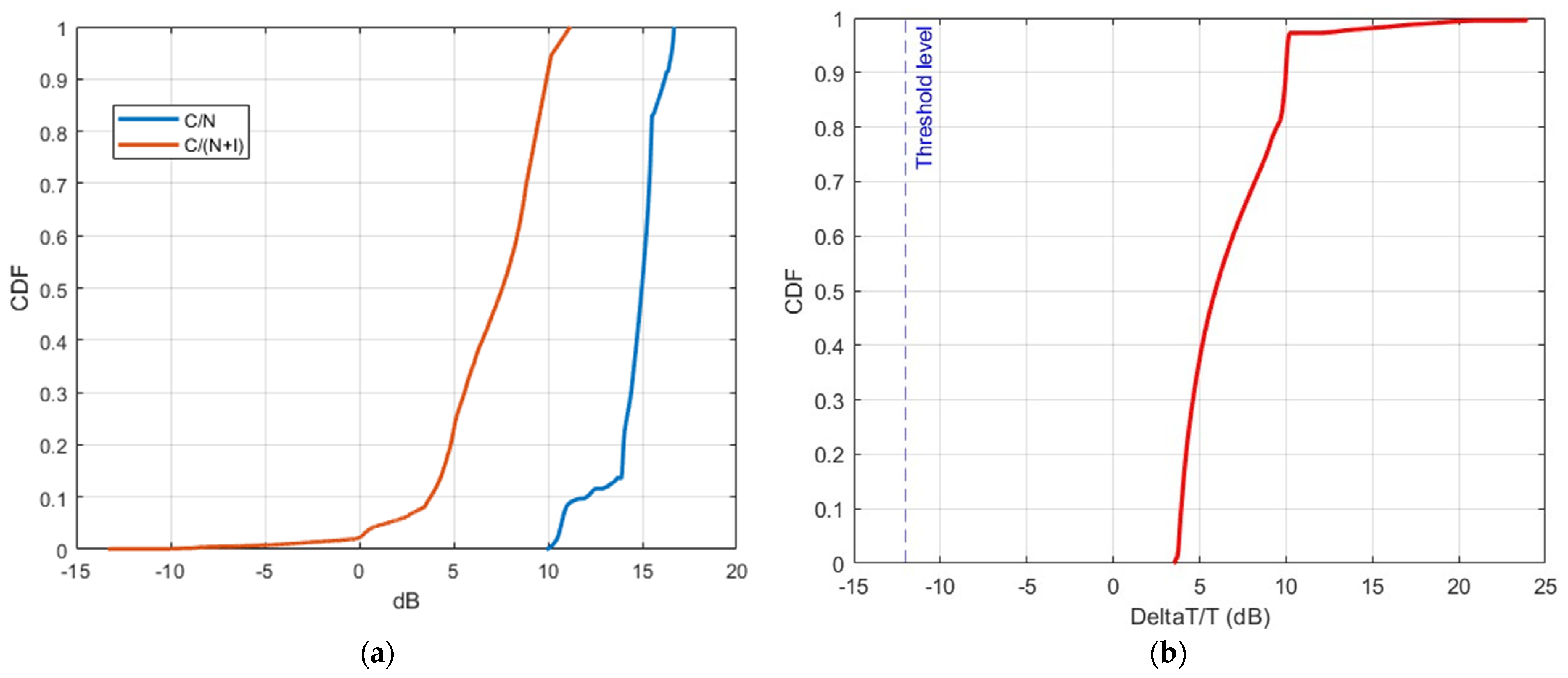
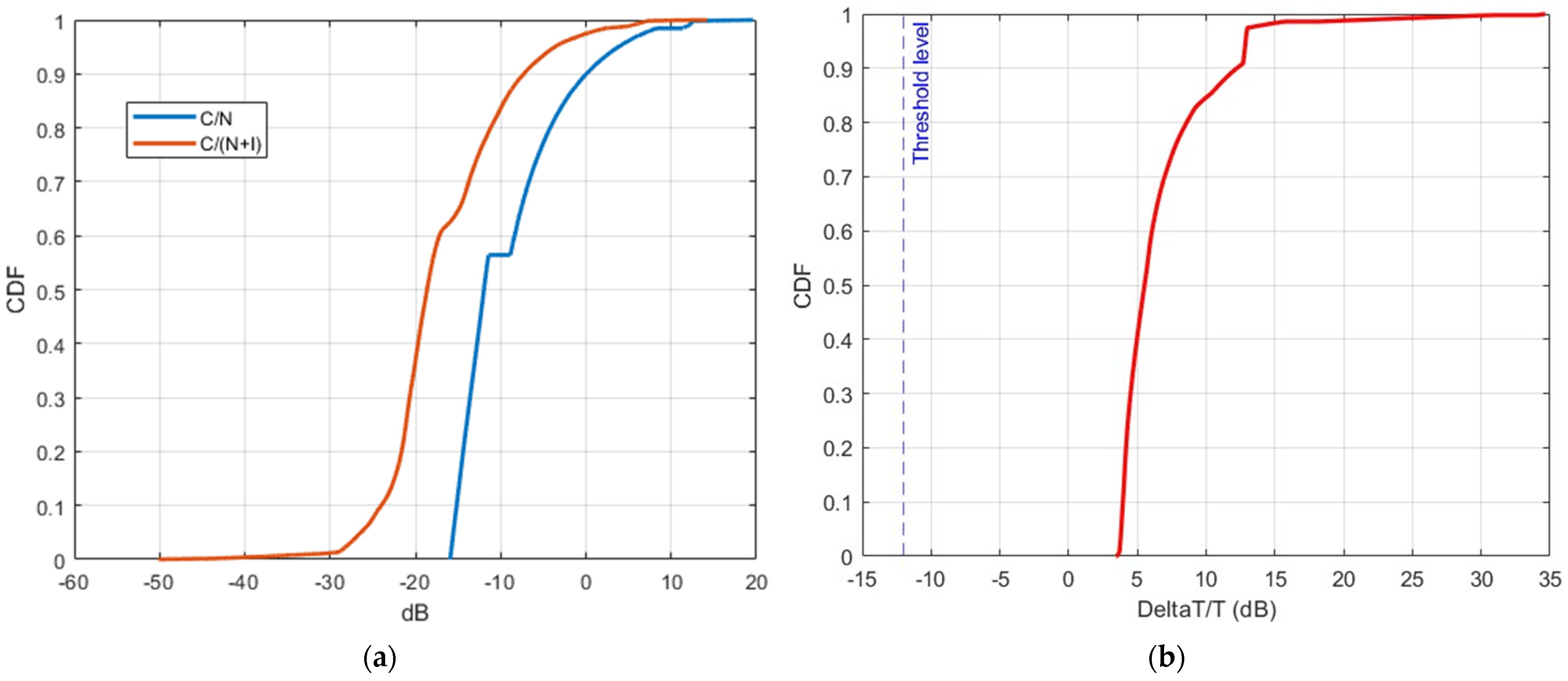
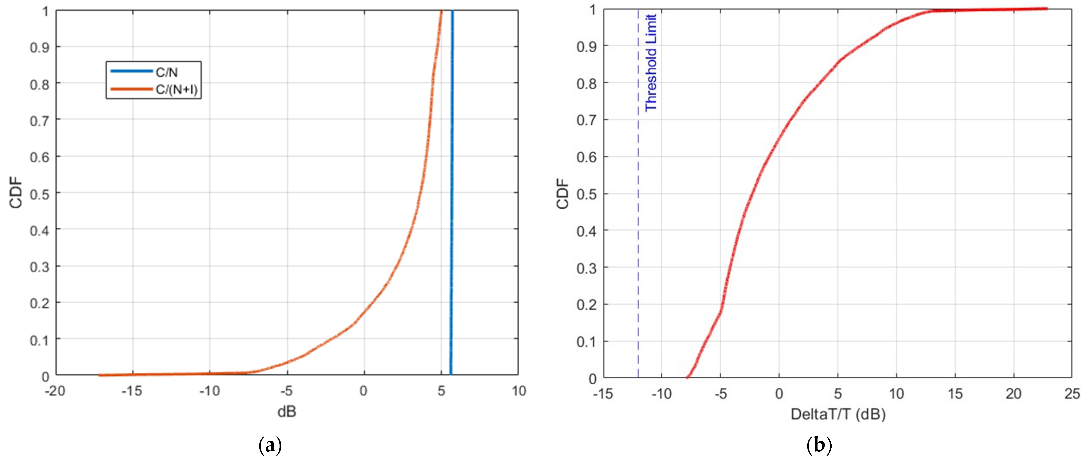
The pictures of the results are divided into two parts, (a) and (b), each providing specific information about the link performance and the receiver’s noise level when the interference is present. In the first part, (a), the blue curve represents the C/N levels at the input of the victim station during the simulation time, indicating the link performance in an interference-free environment. The orange curve represents the C/(N + I) levels, revealing the link performance in the presence of interference caused by the 5G NTN satellite system. In the second part, (b), the graph displays different DeltaT/T values for the Inmarsat receiver’s noise level. This measurement indicates the ratio between the increased noise when interference is present and the noise level in the absence of external interference. Additionally, a punctured line is included in the graph, representing the threshold level at DeltaT/T = −12 dB.
Figure 11 illustrates CDF curves depicting the impact of the 5G NTN satellite system on the DeltaT/T and C/N level degradation of an Omnispace mobile terminal receiver.
The results obtained clearly indicate a significant degradation in the link performance of the Omnispace receiver when interference is present. The C/N levels experience degradation between 6 and 8 dB 100% of time, and in some short periods, it can even reach 15 dB. Such a substantial degradation would have severe consequences, leading to either a tremendous degradation of the service quality or even a complete outage of the radio link. Additionally, it can be seen that the DeltaT/T threshold is exceeded by at least 16 dB and may reach 30 dB overall.
Figure 12 illustrates CDF curves depicting the impact of the 5G NTN satellite system on the DeltaT/T and C/N level degradation of a Lyra mobile terminal receiver.
The results obtained clearly indicate a significant degradation in the Lyra link performance when interference is present. The C/N levels experience a degradation ranging from 1 dB to 10 dB;, in spite of the fact that Lyra is a more interference-robust system, such degradation still may lead to radio link outages and serious delays in message delivery. Additionally, it can be seen that the DeltaT/T threshold is exceeded by at least 16 dB and may reach 28 dB overall.
Figure 13 illustrates CDF curves depicting the impact of the 5G NTN satellite system on the DeltaT/T and C/N level degradation of an Inmarsat Earth station receiver.
The results obtained clearly indicate a significant degradation in the link performance of Inmarsat when interference is present. The C/N levels experience a degradation of at least 1 dB 90% of the time. Even more concerning is the fact that for 18% of the time, the link degrades by more than 5.5 dB. Such a substantial degradation would have severe consequences, leading to either a tremendous drop in service quality or even a complete radio link outage. Additionally, it can be seen that the DeltaT/T threshold is exceeded by at least 5 dB and may reach 20 dB overall.

6. Conclusions

Today, many users prioritize greater accessibility over higher data rates. This preference is driven by the increasing number of people who enjoy traveling to remote places with limited connectivity but still require basic features such as text messaging, voice calls, and basic web browsing. Therefore, achieving seamless compatibility with other NGSO systems is vital to ensure the success of NTN technology in these frequency bands. Consequently, the development of 5G NTN and 6G NTN systems becomes crucial as they bridge this gap for numerous individuals. Moreover, the demand for direct-to-cellular NTN systems in smartphones is currently on the rise, allowing users to access these features in one device.
To meet users’ needs effectively, it is essential to develop NTN systems supported by 3GPP frequency bands. This eliminates the need for users to purchase additional phones when traveling to remote areas. In line with this goal, 3GPP has added support for n255 and 256 bands. However, implementing NTN systems in these bands requires compatibility with other NGSO systems. This is due to the complexity of spectrum sharing in satellite systems, given their global nature of operations compared to terrestrial systems.
The study examined the impact of a 5G/6G NTN satellite system on incumbent satellite systems in the n255 and n256 bands, revealing a significant challenge in implementing a new NGSO system with contiguous coverage and satisfactory link performance to support 5G and 6G services in these bands. The results unequivocally demonstrate a substantial degradation in link performance and potential adverse effects on the incumbent satellite systems when they are subjected to interference from the 5G/6G NTN satellite system in these frequency bands.
The study considered three incumbent satellite networks, and the results indicate that for Inmarsat, the results clearly demonstrate a significant degradation in link performance when subjected to interference. This poses a substantial threat, potentially resulting in a drastic decline in service quality or even complete radio link outages. Similarly, Omnispace experiences a significant degradation in link performance when exposed to interference. This degradation has severe implications, potentially leading to a significant drop in service quality or complete radio link outages. In the case of Lyra, even though it is a more interference-robust system, the study demonstrates a substantial degradation in link performance when external interference is present. Despite the system’s robustness, such degradation can still result in radio link outages and significant delays in message delivery.
These findings strongly discourage the deployment of the 5G NTN network in the n255 and n256 bands as it would compromise the quality of service, result in radio link outages, and hinder the timely delivery of messages. Additionally, coordination with other operators and administrations within the ITU-R for filing such a system would be practically impossible. This means that providing the required 5G and 6G services in these bands is not feasible in the foreseeable future. While the existing systems in these bands, such as those used by MVNOs for the NB-IoT services provided by Inmarsat, Echostar, Thuraya, and others, may have limited capabilities, since they were not designed to support the full range of services with the lower latency and fast data rate requirements that are the part of the 5G ecosystem and will be a part of the 6G ecosystem. Considering these limitations, it is prudent to explore alternative spectrum bands in which new constellations can be launched to provide the necessary voice and data services based on the 5G and 6G radio interfaces. Future studies should focus on identifying suitable bands that can accommodate these services effectively.
In summary, this study highlights the significant challenges and adverse effects associated with deploying a new 5G NTN satellite system in the n255 and n256 bands. To ensure the provision of robust and reliable 5G and 6G services while avoiding interference and maintaining the service quality of the incumbent satellite systems, exploring alternative spectrum bands becomes crucial. The provision of the NTN services within existing satellite systems in the n255 and n256 bands also presents problems mentioned above.
As a more feasible solution for future NTN systems, sharing the spectrum with terrestrial cellular systems is recommended. This approach eliminates the need for complex coordination procedures and reduces restrictions on the NTN systems, facilitating better integration and improved service provision. However, this approach requires further studies and evaluation.

Author Contributions

Conceptualization, A.P. and V.T.; methodology, A.P. and O.V.; software, A.P.; validation, A.P.; formal analysis, V.T. and O.V.; investigation, V.T. and S.D.; resources, S.D. and O.V.; data curation, A.P.; writing—original draft preparation, A.P. and S.D.; writing—review and editing, S.D. and O.V.; visualization, A.P.; supervision, O.V.; project administration, S.D.; funding acquisition, V.T. All authors have read and agreed to the published version of the manuscript.

Funding

This research received no external funding.

Institutional Review Board Statement

Not applicable.

Informed Consent Statement

Not applicable.

Data Availability Statement

Not applicable.

Acknowledgments

The authors would like to thank the Radio Research and Development Institute, Moscow, Russia for providing valuable technical resources to conduct this study and Geyser-Telecom, Ltd., Moscow, Russia, for extensive consultation and important suggestions regarding the assumptions used in this study.

Conflicts of Interest

The authors declare no conflict of interest.

References

  1. Courville, N.; Bischl, H.; Lutz, E.; Svigelj, A.; Chan, P.M.; Papapetrou, E.; Asorey-Cacheda, R. Hybrid satellite/terrestrial networks: State of the art and future perspectives. In QShine 2007 Workshop: Satellite/Terrestrial Interworking (IWSTI ‘07); Association for Computing Machinery: New York, NY, USA, 2007; Volume 1, pp. 1–7. [Google Scholar] [CrossRef]
  2. Daneshmand, B. Comparative analysis of the concept of creation and development of 5G/IMT-2020 networks in Russia, China, USA and Europe. T-Comm 2021, 15, 20–32. [Google Scholar] [CrossRef]
  3. Reiner Stuhlfauth: 5G NTN Takes Flight: Technical Overview of 5G Non-Terrestrial Networks; White Paper; Rohde & Schwarz: Munich, Germany, 2022; Available online: https://www.microwavejournal.com/articles/39205-5g-ntn-takes-flight-technical-overview-of-5g-non-terrestrial-networks (accessed on 19 February 2023).
  4. Pastukh, A.S.; Boltaev, R.A.; Devyatkin, E.E.; Ivankovich, M.V. Study of implementation options of the direct satellite-to-smartphone 4G-6G networks. Trudi NIIR 2022, 4, 56–72. (In Russian) [Google Scholar] [CrossRef]
  5. Dymkova, S. Breakthrough 5G data call using dynamic spectrum sharing to accelerate nationwide 5G deployments. Synchroinfo J. 2019, 5, 17–21. [Google Scholar]
  6. Federal Communications Comission. Single Network Future: Supplemental Coverage from Space Notice of Proposed Rulemaking. Available online: https://www.fcc.gov/document/fcc-proposes-framework-facilitate-supplemental-coverage-space-0 (accessed on 9 March 2023).
  7. Panaitopol, D.; Jin, Y.; Tang, R.; Park, C. Requirements on Satellite Access Node and User Equipment for Non-Terrestrial Networks in 5G New Radio of 3GPP Release-17; Special issue Paper; Wiley: Hoboken, NJ, USA, 2022. [Google Scholar]
  8. Martikainen, H.; Majamaa, M.; Puttonen, J. Coordinated Dynamic Spectrum Sharing Between Terrestrial and Non-Terrestrial Networks in 5G and Beyond. arXiv 2023, arXiv:2304.12112. [Google Scholar] [CrossRef]
  9. Courville, N.; Bischl, H.; Lutz, E.; Svigelj, A.; Chan, P.M.L.; Papapetrou, E.; Rafael. 3GPP TR 38.863. Non-Terrestrial Networks (NTN) Related RF and Co-Existence Aspects. Available online: https://portal.3gpp.org/desktopmodules/Specifications/SpecificationDetails.aspx?specificationId=3926 (accessed on 6 June 2023).
  10. Sormunen, L.; Martikainen, H.; Puttonen, J.; Panaitopol, D. Co-existence of Terrestrial and Non-Terrestrial Networks on Adjacent Frequency Bands. In Proceedings of the 11th Advanced Satellite Multimedia Systems Conference and the 17th Signal Processing for Space Communications Workshop (ASMS/SPSC), Graz, Austria, 6–8 September 2022; pp. 1–6. [Google Scholar] [CrossRef]
  11. Wang, T.; Li, W.; Li, Y. Co-Frequency Interference Analysis Between Large-Scale NGSO Constellations and GSO Systems. In Proceedings of the 2020 International Conference on Wireless Communications and Signal Processing (WCSP), Nanjing, China, 21–23 October 2020; pp. 679–684. [Google Scholar] [CrossRef]
  12. 3GPP TR 36.821. Solutions for NR to Support Non-Terrestrial Networks (NTN). Available online: https://portal.3gpp.org/desktopmodules/Specifications/SpecificationDetails.aspx?specificationId=3525 (accessed on 6 June 2023).
  13. 3GPP TR 36.763. Study on Narrow-Band Internet of Things (NB-IoT)/Enhanced Machine Type Communication (eMTC) Support for Non-Terrestrial Networks (NTN). Available online: https://portal.3gpp.org/desktopmodules/Specifications/SpecificationDetails.aspx?specificationId=3747 (accessed on 18 May 2023).
  14. International Telecommunication Union. Report ITU-R S.2514 Report ITU-R M.2514-0 Vision, Requirements and Evaluation Guidelines for Satellite Radio Interface(s) of IMT-2020. Available online: https://www.itu.int/pub/R-REP-M.2514-2022 (accessed on 3 April 2023).
  15. International Telecommunication Union. ITU-R S.1528 Satellite Antenna Radiation Patterns for Non-Geostationary Orbit Satellite Antennas Operating in the Fixed-Satellite Service below 30 GHz. Available online: https://www.itu.int/rec/R-REC-S.1528/en (accessed on 25 May 2023).
  16. International Telecommunication Union. Mobile Satellite Service (MSS) Handbook; International Telecommunication Union: Geneva, Switzerland, 2005. [Google Scholar]
  17. Richaria, M.; Westbrook, L.D. Satellite Systems for Personal Applications Concepts and Technology; Wiley: New York, NY, USA, 2010. [Google Scholar]
  18. International Telecommunication Union. Recommendation ITU-R S.672 Satellite Antenna Radiation Pattern for Use as a Design Objective in the Fixed-Satellite Service Employing Geostationary Satellites. Available online: https://www.itu.int/rec/R-REC-S.672/en (accessed on 21 May 2023).
  19. International Telecommunication Union. Recommendation ITU-R S.2131 Method for the Determination of Performance Objectives for Satellite Hypothetical Reference Digital Paths Using Adaptive Coding and Modulation. Available online: https://www.itu.int/rec/R-REC-S.2131-1-202201-I/en (accessed on 6 June 2023).
  20. Pastukh, A.; Tikhvinskiy, V.; Devyatkin, E.; Kostin, A. Interference Analysis of 5G NR Base Stations to Fixed Satellite Service Bent-Pipe Transponders in the 6425–7125 MHz Frequency Band. Sensors 2023, 23, 172. [Google Scholar] [CrossRef] [PubMed]
  21. Pahl, J. Interference Analysis: Modelling Radio Systems for Spectrum Management; Wiley: New York, NY, USA, 2016; Volume 3, pp. 43–142. [Google Scholar]
  22. International Telecommunication Union. Recommendation ITU-R P.525 Calculation of Free-Space Attenuation. Available online: https://www.itu.int/rec/R-REC-P.525/en (accessed on 6 June 2023).
  23. Diachkova, M.N.; Kantor, L.Y.; Nozdrin, V.V.; Timofeev, V.V.; Smirnova, T.V.; Simonov, M.M.; Pastukh, S.Y.; Mysev, M.V.; Zheltonogov, I.V.; Yermilov, V.T. Electromagnitnaia Sovmestimost’system Sputnikovoi Sviazy. [Electromagnetic Compatibility of Satellite Communication Systems]; NIIR Publisher: Moscow, Russia, 2009; Volume 2, pp. 45–107. [Google Scholar]
  24. International Telecommunication Union. Recommendation ITU-R P.619 Propagation Data Required for the Evaluation of Interference between Stations in Space and Those on the Surface of the Earth. Available online: https://www.itu.int/rec/R-REC-P.619/en (accessed on 16 April 2023).
  25. Ippolito, L., Jr. Satellite Communications Systems Engineering Atmospheric Effects, Satellite Link Design and System Performance; Wiley: New York, NY, USA, 2009; Volume 9, pp. 241–264. [Google Scholar]
  26. Elbert, B. Radio Frequency Interference in Communications Systems; Artech House: Boston, MA, USA, 2016; Volume 4, pp. 65–89. [Google Scholar]
  27. Mazar, H. Radio Spectrum Management: Policies, Regulations and Techniques; Wiley: New York, NY, USA, 2019; Volume 5, pp. 150–225. [Google Scholar]
  28. International Telecommunication Union. Radio Regulations 2020. Available online: https://www.itu.int/pub/R-REG-RR (accessed on 6 June 2023).
  29. Sklar, B. Digital Communications Fundamentals and Applications; University of California: Los Angeles, CA, USA; Prentice Hall: Upper Saddle River, NJ, USA, 2003; Volume 5, pp. 242–305. [Google Scholar]
Figure 1. NTN typical scenario according to 3GPP TR 38.821.
Technologies 11 00110 g001
Figure 2. Simulation of the 5G-6G NTN constellation.
Technologies 11 00110 g002
Figure 4. Simulation of the wanted Inmarsat Aero link (space-to-Earth) in the L-band.
Technologies 11 00110 g004
Figure 5. Simulation of the wanted Omnispace F2 link (space-to-Earth).
Technologies 11 00110 g005
Figure 6. Simulation of the wanted Lyra link (space-to-Earth).
Technologies 11 00110 g006
Figure 7. Interference scenario in which the NTN satellite interferes with the incumbent system’s Earth station.
Technologies 11 00110 g007
Figure 8. Simulation of the interference transmitted from the 5G NTN system to the Omnispace system.
Technologies 11 00110 g008
Figure 9. Simulation of the interference from a 5G NTN system in the Lyra system.
Technologies 11 00110 g009
Figure 10. Simulation of the interference from the 5G NTN system in the Inmarsat system.
Technologies 11 00110 g010
Figure 11. CDF curves representing interference at the Omnispace receiver: (a) C/N and C/(N + I); (b) DeltaT/T.
Technologies 11 00110 g011
Figure 12. CDF curve of interference at the Lyra receiver: (a) C/N and C/(N + I); (b) DeltaT/T.
Technologies 11 00110 g012
Figure 13. CDF curve of interference at the Inmarsat receiver: (a) C/N and C/(N + I); (b) DeltaT/T.
Technologies 11 00110 g013
Table 1. Frequency spectrum in the S-band and L-band (FR1) for NTN usage.
NTN Satellite BandUplink (UL) Operating Band
Satellite Access Node Receive/UE Transmit
FUL,low–FUL,high
Downlink (DL) Operating Band
Satellite Access Node Transmit/UE Receive
FDL,low–FDL,high
Duplex Mode
n2561980–2010 MHz2170–2200 MHzFDD
n2551626.5–1660.5 MHz1525–1559 MHzFDD
Table 2. Example parameters used in evaluations for handheld and MTD terminals.
ParameterRural-eMBB-sRural-mMTC-sRural-HRC-s
Terminal typeHandheldMTD
Handheld
Handheld
Satellite orbit
configuration
LEO, 600 km altitude
Spot beam patternHexagonal pattern; at least 19 spot beams.
Service link
frequency
2 GHz
Channel bandwidth30 MHz30 MHz180 kHz–3 MHz
3 dB beam width4.41 degrees
Satellite EIRP density34 dBW/MHz
Satellite antenna gain30 dBi
Satellite G/T1.1 dB/K
Device deployment100% outdoors; randomly and uniformly distributed over the area.
UE density10 UEs per spot beam.At least 500 per km210 UEs per spot beam.
UE mobility modelFixed and identical speed of 250 km/h of all UEs, randomly and uniformly distributed direction.
For all other evaluations: Stationary.
StationaryFixed and identical speed of 30 km/h of all UEs, randomly and uniformly distributed direction.
Traffic modelFull bufferMessage size of 32 bytes: 1 message/day/device
or
1 message/2 h/device
Packet arrival follows Poisson arrival process for non-full buffer system-level simulation
Full buffer
UE antenna height1.5 m
Table 3. Orbital parameters of the simulated 5G satellite NTN.
ParameterValue
Type of the orbitCircular
Altitude600 km
Number of orbital planes14
Number of satellites per plane32
True anomaly phasing11.25 degrees
RAAN increment25.7 degrees
Table 4. The link characteristics of Inmarsat 25E for Aero terminals.
Carrier
Assignment
Carrier Power, Max (dBW)Carrier Power, Min (dBW)Sat. TX Gain (dBi)ES TypeES Gain (dBi)ES Sidelobe
Formula
Noise Temp. (K)
17K5G1W--1.9−4.322INM-AERO (H) C-2112.0IF (topo ≥ 45, −1,12)316.2
7K50G1W--0.3−4.422INM-AERO (H) P-10.512.0IF (topo ≥ 45, −1,12)316.2
7K50G1W--−1.0−7.722INM-AERO (H) C-8.412.0IF (topo ≥ 45, −1,12)316.2
2K50G1W--−7.6−12.722INM-AERO (H) P-1.212.0IF (topo ≥ 45, −1,12)316.2
2K50G1W--−10.7−15.822INM-AERO (H) P-0.612.0IF (topo ≥ 45, −1,12)316.2
5K00G1W--2.5−2.222INM-AERO (I) P-4.86.0IF (topo ≥ 80, −1,6)316.2
2K50G1W--−1.6−6.722INM-AERO (I) P-1.26.0IF (topo ≥ 80, −1,6)316.2
2K50G1W--−4.7−9.822INM-AERO (I) P-0.66.0IF (topo ≥ 80, −1,6)316.2
2K50G1W--5.40.322INM-AERO (L) P-1.20.0Omni398.1
2K50G1W--2.3−2.822INM-AERO (L) P-0.60.0Omni398.1
Table 5. The link characteristics of the Omnispace F2 satellite.
Carrier
Assignment
Carrier Power, Max (dBW)Carrier Power, Min (dBW)Sat. TX Gain (dBi)ES TypeES Gain (dBi)ES Sidelobe
Formula
Noise Temp. (K)
10M0G7D--17934MES-1, MES-24, 12ND-EARTH300
100KG1W--17934MES-1, MES-24, 12ND-EARTH300
100KG1D--231534MES-1, MES-24, 12ND-EARTH300
50K0G1W--14634MES-1, MES-24, 12ND-EARTH300
50K0G1D--201234MES-1, MES-24, 12ND-EARTH300
25K0G7W--11334MES-1, MES-24, 12ND-EARTH300
25K0G7D--17934MES-1, MES-24, 12ND-EARTH300
5K00G1W--11334MES-1, MES-24, 12ND-EARTH300
5K00G1D--17934MES-1, MES-24, 12ND-EARTH300
Table 6. The link characteristics of the Lyra satellite system.
Carrier
Assignment
Carrier Power, Max (dBW)Carrier Power, Min (dBW)Sat. TX Gain (dBi)ES TypeES Gain (dBi)ES Sidelobe FormulaNoise Temp. (K)
28K0G1W--18−711RTU-114AP8290
14K0G1W--15−1011RTU-114AP8290
5K60G1W--17−811RTU-114AP8290
2K80G1W--14−1111RTU-114AP8290
1K40G1W--11−1411RTU-114AP8290
Disclaimer/Publisher’s Note: The statements, opinions and data contained in all publications are solely those of the individual author(s) and contributor(s) and not of MDPI and/or the editor(s). MDPI and/or the editor(s) disclaim responsibility for any injury to people or property resulting from any ideas, methods, instructions or products referred to in the content.

