Article

Computational Investigation of a Tibial Implant Using Topology Optimization and Finite Element Analysis

by
Nikolaos Kladovasilakis
1,
Theologos Bountourelis
1,
Konstantinos Tsongas
1,2 and
Dimitrios Tzetzis
1,*
1
Digital Manufacturing and Materials Characterization Laboratory, School of Science and Technology, International Hellenic University, 57001 Thessaloniki, Greece
2
Department of Industrial Engineering and Management, School of Engineering, International Hellenic University, 57001 Thessaloniki, Greece
*
Author to whom correspondence should be addressed.
Technologies 2023, 11(2), 58; https://doi.org/10.3390/technologies11020058
Submission received: 15 March 2023 / Revised: 10 April 2023 / Accepted: 12 April 2023 / Published: 13 April 2023

Abstract

:
Additive manufacturing methods enable the rapid fabrication of fully functional customized objects with complex geometry and lift the limitations of traditional manufacturing techniques, such as machining. Therefore, the structural optimization of parts has concentrated increased scientific interest and more especially for topology optimization (TO) processes. In this paper, the working principles and the two approaches of the TO procedures were analyzed along with an investigation and a comparative study of a novel case study for the TO processes of a tibial implant designed for additive manufacturing (DfAM). In detail, the case study focused on the TO of a tibial implant for knee replacement surgery in order to improve the overall design and enhance its efficiency and the rehabilitation process. An initial design of a customized tibial implant was developed utilizing reserve engineering procedures with DICOM files from a CT scan machine. The mechanical performance of the designed implant was examined via finite element analyses (FEA) under realistic static loads. The TO was conducted with two distinct approaches, namely density-based and discrete-based, to compare them and lead to the best approach for biomechanical applications. The overall performance of each approach was evaluated through FEA, and its contribution to the final mass reduction was measured. Through this study, the maximum reduction in the implant’s mass was achieved by maintaining the mechanical performance at the desired levels and the best approach was pointed out. To conclude, with the discrete-based approach, a mass reduction of around 45% was achieved, almost double of the density-based approach, offering on the part physical properties which provide comprehensive advantages for biomechanical application.

1. Introduction

Structural optimization is a discipline dealing with the optimal design for load-carrying mechanical structures in order to reduce their overall mass and improve their functionality [1]. There are three levels of structural optimization: size, shape, and topology optimization [2]. The size optimization calculates the minimum dimensions of an element (for example, a shaft diameter) of a part in order to withstand the applied loads. Shape optimization finds the optimal form of a structure to improve its functionality. Furthermore, topology optimization (TO) calculates the minimum mass and its optimal distribution in a defined external volume in order to handle the applied loads and achieve the desired goals. These processes are not new concepts since several engineers have employed them in various constructions through the years, from gears to truss bridges. However, the implementation of an overall structural optimization was limited due to the lack of proper computational tools, such as mechanical simulation software, and the restriction of the manufacturing processes, such as machining [2,3]. In detail, the most advanced level of structural optimization, namely topology optimization, requires multiple finite element analyses (FEAs) to extract the optimal design, which, in most cases, has high complexity. For these reasons, advanced manufacturing methods, such as additive manufacturing (AM), are essential to be utilized coupled with sophisticated simulation software.
AM technologies have gained increased scientific interest and have been rapidly developed in recent years. More specifically, AM methods are the manufacturing techniques that create desired objects by fabricating them layer by layer directly from the feedstock material, with each layer having the corresponding cross-sections of the item [3,4]. Therefore, AM techniques are radically differentiated from traditional manufacturing methods. There are eight distinct categories of AM methods, according to international standards [5]. Table 1 provides a summary of each AM technology, accompanied by a brief explanation. AM methods have numerous benefits in terms of both manufacturability and productivity. Among the primary advantages of AM processes are the quick production of prototypes and functional parts, the relatively low cost of producing customized parts, and the ability to manufacture objects with intricate geometries [4,6]. These advances in additive manufacturing processes led to the rapid development of topology optimization procedures [7].
Topology optimization aims to discover the optimal distribution of minimum required material mass within a predefined design volume in order to satisfy specific engineering or design criteria, such as maximum stress under given operating loads [2,8]. The outcome of this process is a reduction in weight and an increase in the object’s specific strength. Topology optimization is a mathematical optimization problem with iterative configuration. Thus, the fundamental tool for the topology optimization process is the finite element analyses (FEAs), which are performed multiple times until the objective is achieved. This mathematical optimization problem consists of design variables, constraints, and objective functions. Design variables are the parameters that can be adjusted in the design of a part (shape, geometry, etc.). Constraints are the limitations on the design variables derived from the functionality of the part, the manufacturing capabilities, etc. Finally, objective functions are mathematical formulations that express the performance of the designed part, such as flexibility or potential deformation energy, volume, displacement, strength characteristics, etc. Currently, topology optimization is performed via two main approaches: the element-based approach with several methods, i.e., density-based, topological derivatives, level set, phase field, etc., and the discrete/truss approach, which implements lattice structures in the design with two methods: lattices designed with evolutionary-based algorithms and the employment of architected materials in the part [9].
Thus, the objective of this paper is to provide a comprehensive analysis of topology optimization processes, together with a real-life biomechanical application, to facilitate the commercialization of these procedures. The study examines two methods: density-based and discrete/truss-based approaches, presenting and analyzing them in detail. Specifically, the density-based approach’s most common algorithms were introduced, along with their mathematical algorithms. Concerning the discrete/truss-based approach, the paper presents the introduction of architected materials and offers a comprehensive classification based on their geometry. Additionally, the unique characteristics of architected materials have been presented along with their most promising and cutting-edge applications. The final section of the paper features a case study of topology optimization for a biomechanical application.

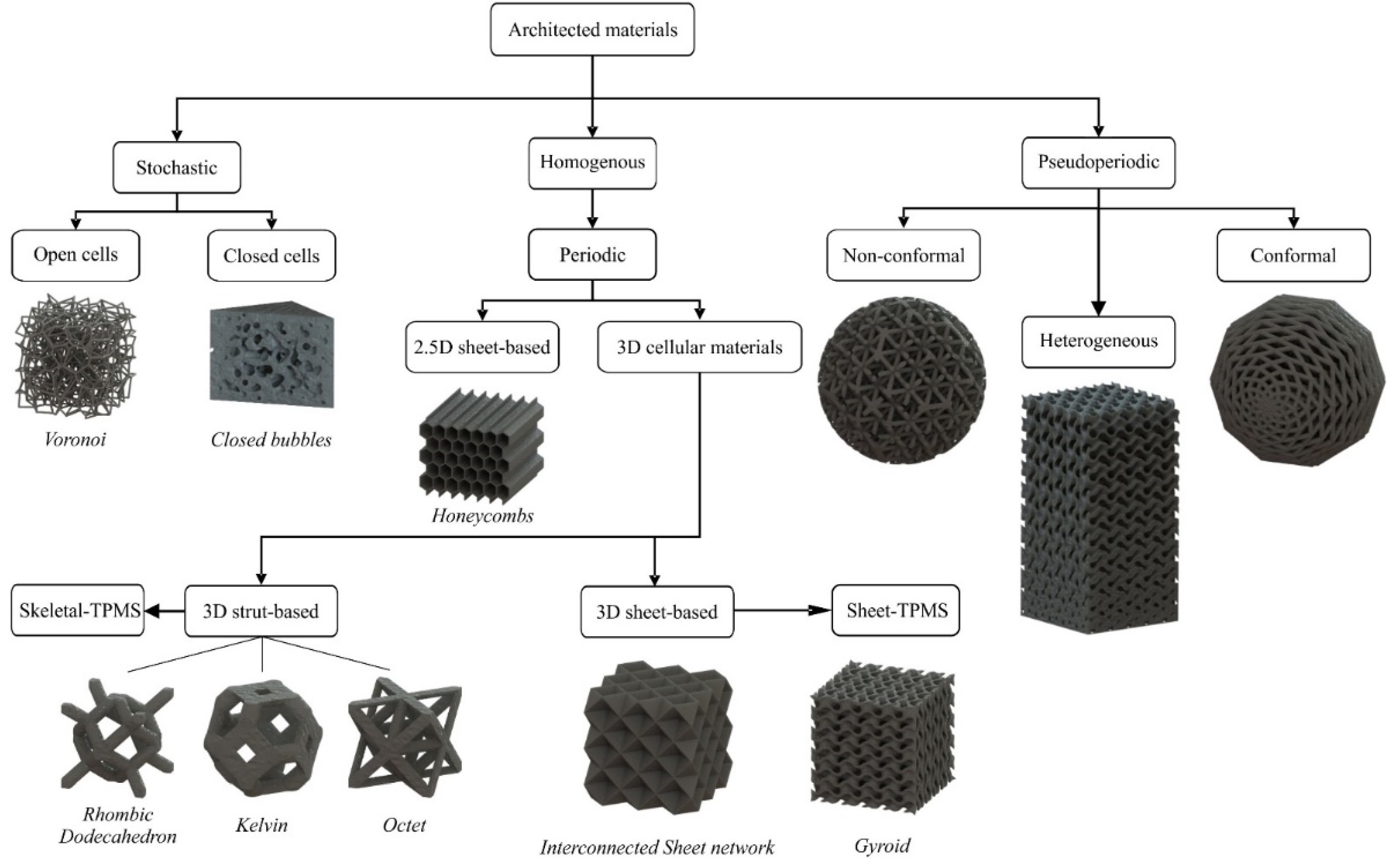
2. Topology Optimization Methodologies

2.1. Density-Based Approach

The conditional density method is utilized in density-based structural topology optimization. In the design-based process, the volume domain of the part is divided into voxels, and each finite element is assigned a conditional density value ranging from zero to one. The density value is determined by each element’s contribution to the total strength of the designed part. Elements that play a significant role in the part’s structural integrity have a density value of one, while those with minimal contribution are assigned a value of zero. All other elements are assigned intermediate values of conditional densities. The algorithms studied in this work were the SIMP, the ESO, and BESO. The ESO and BESO algorithms have been examined intensively. ESO is based on the simple concept of gradually removing inefficient material from the structure’s volume domain. The resulting structure of the ESO method evolves toward its optimal shape and topology. The ESO method is commonly used and quite helpful for engineers focused on investigating structurally effective shape forms during the conceptual design stage of a project. This optimization algorithm can be employed for both large-scale structures as well as for the optimization of micro-scale and nano-scale structures. The ESO technique was introduced in 1992 by M. Xie and G. Steven [10]. The ESO method is a so-called hard destruction technique since it enables repetitive removal or addition of finite amounts of material. Heuristic criteria are employed that can be based on well-defined sensitivity information. Hence, the implementation of the ESO method is relatively straightforward, making it advantageous for topology optimization problems that involve complicated physical processes. ESO technique, along with FEA, may estimate the stress level of an arbitrary partition of a structure [11]. A low level of stress in the individual part of a structure will help to determine the ineffective use of the material. It would be preferable to distribute the stress level all over the structure according to the safety factor. Based on that, the principle of material removal has been established, where insufficiently loaded material is removed from the individual elements of the finite element model. Comparing the stress σevm element with the critical or maximum value σmaxvm of the object determines the stress level of that element. If the element satisfies the following condition:
σ e vm σ max 0 vm < R Ri
where RR denotes the limit value or the subtraction rate at which an element is removed, and the control process initiates a new cycle. The testing of individual components is conducted iteratively until a steady state is attained, wherein no additional components meet the subtraction limit. The subtraction rate can be increased based on the specific evolution rate H i , as determined by the following equation:
R R i + 1 = R Ri + H i
The previously outlined process can be utilized to increase the subtraction ratio, and FEA is conducted until a new steady-state equilibrium is established. For example, the process continues until all material is eliminated from regions where the stress level is below 20% of the maximum material stress. The elasticity index, which is defined for the mean elasticity, can be used to quantitatively evaluate the change in stiffness of the structure as a consequence of the subtraction of the i-th finite element, as shown in the following equation [10], where the node displacement vector of element I is denoted as ui, while Ki represents the stiffness matrix of the element.
α i e = 1 2 u i T K i u i
The sensitivity function indicates the extent to which the average stiffness is decreased when the i-th element is eliminated, which corresponds to the elemental deformation energy of the i-th element. To retain stiffness while removing elements, it is crucial to remove elements with the lowest sensitivity factor value [10]. The ESO algorithm’s mathematical formulation is straightforward and can be used for both 2D and 3D problems. Its software application does not require complex programming. To remove elements, their equation coefficient is set to zero, and they are ignored in subsequent repetitions. The iterative removal process reduces the number of equations, making it ideal for computationally demanding 3D problems. However, a major drawback of the ESO method is that it does not allow for the recovery of removed material, which could be useful in future designs. Therefore, the ESO method may not always provide the optimal solution, and this disadvantage is addressed by the BESO method.
The BESO algorithm enables both the removal and addition of material in the design volume simultaneously. Unlike the ESO method, the sensitivity index of empty elements in the BESO algorithm is determined using linear extrapolation of the displacement field resulting from finite element analysis (FEA). The full elements with the lowest sensitivity index values are then removed from the structure, while the empty elements with the highest sensitivity values are filled with material. The number of elements that are removed and added at each iteration is controlled by two independent parameters: the RR subtraction ratio and the RI inclusion ratio.
The SIMP algorithm is the third and most commonly used method for topology optimization. It should be noted that most commercial design software employs this algorithm, and it was also used in this study for the optimization of the tibial implant. The basic concept of the SIMP method is to create a virtual density field that reflects the actual characteristics of the structure being studied [12]. SIMP technique decreases the compliance of the structure due to the reallocation of the material in the examination area under specific limit conditions. The result of using the SIMP method is that the object maintains the same stiffness values within the under-consideration area. The SIMP method has been extensively employed in additive manufacturing constructs. The material density is considered a design variable for the calculation stage of the optimization. To obtain an optimal structure within a defined domain, the SIMP algorithm redistributes the material based on specified optimization criteria. Like other topology optimization methods, the SIMP approach also involves dividing the volume under investigation into small voxels. The material properties are kept constant in each of these elements and depend on the relative density xi. At the end of the optimization process, each element’s relative density should be either one or zero. To prevent intermediate values of relative density, a rejection factor of p is employed. The design variables are set, and the objective function is chosen as the mean correspondence between the relative densities of the elements. The problem of topology optimization for minimum correspondence can be formulated as follows:
Find :   X = x 1 , x 2 , , x i   T   , i = 1 , 2 , , n Min :   C X = F T U = U T K U = i = 1 n u i T k i u i = i = 1 n x i P u i T k 0 u i Subj .   to :   KU = F ,   V = f 0 V 0 = i = 1 n x i v i with :   0 < x min x i x max 1
where:
  • C is the objective function and is defined as the mean correspondence;
  • X is the vector of construction variables;
  • F is the loading vector;
  • U is the total displacement vector;
  • K is the total stiffness strain;
  • V is the material’s volume;
  • f0 is the volumetric ratio.
The ESO–SIMP method is the most efficient density-based algorithm, which combines the ESO and SIMP methods to overcome their disadvantages [13]. In this method, the relative densities are chosen as the design variables, and the objective function is set as the minimum mean correspondence. To solve the optimization problem, the ESO–SIMP algorithm is used, and its expression for the minimum mean correspondence is as follows:
Find :   X = x 1 , x 2 , , x i   T   , i = 1 , 2 , , n Min :   C X = U T K U = i = 1 n u i T k i u i = i = 1 n x i P u i T k 0 u i Subj .   to :   KU = F ,   V = i = 1 n x i v i f 0 V 0 with :   0 < x min x i x max 1
The difference between the ESO–SIMP and SIMP methods is the volume limitation. During each iteration, elements whose relative density is less or equal to the rejection factor are removed from the design volume and all other elements are inserted into the next iteration. This combination method turns out to be more appropriate than an individual ESO or SIMP in terms of efficiency and reliability.

2.2. Discrete/Truss-Based Approach

The discrete/truss-based approach with the implementation of architected materials in the lattice structure of a part has gained increased scientific and commercial interest due to the transfusion of comprehensive advantages in the structure, such as lightweight, high porosity, etc. The lattice structures were observed from ancient times in the form of cellular materials in nature, such as foams, coral, etc., and in many cases, attempts were made to imitate in artificial structures, such as honeycombs [14]. In the last decade, artificial lattices have regained interest due to the developments in additive manufacturing techniques and their ability to fabricate these complex geometries. The lattices consist of architected materials with various shapes and topology properties. Currently, there is a huge number of architected materials; however, all of them have one common physical characteristic, which is the applied relative density [15]. The relative density in lattice structures is the percentage of the volume that is filled with the employed architected material. This percentage is highly influenced by the ratio of the structure thickness to the unit cell length, according to the existing literature [16,17,18]. The relative density of an architected material could be regulated in such a way as to produce structures with desired mass and specific mechanical properties. Thus, the architected materials are employed in topology optimization processes through the discrete-based approach. The lattice structures are divided into three categories depending on the applied relative density. The first category contains structures with architected materials with ultra-low relative density (<5%), and it is referred to as foams. The second category concerns the lattice structures with a range, for relative density of the architected material, between 10% and 60%. Finally, for the architected materials with relative densities above 70%, the structure’s elements (beams/surfaces) are overlapped, diverging the lattice structure configuration [15].
This vast number of architected materials led to the need for classification. According to the existing literature [19,20], there are at least two different types of classification of architected materials based on their geometry and based on their mechanical behavior. However, the most significant classification is geometry-based because it is focused only on the design of the architected material. The architected materials can be classified into three categories based on the periodicity of the structure: stochastic, periodic, and pseudo-periodic. Stochastic lattices can be found in nature or can be designed using random seed functions and algorithms, such as the Voronoi algorithm [21]. Periodic structures have a repeated unit cell in all three dimensions, while pseudo-periodic structures consist of periodic lattices that are interrupted or interactive with the overall structure boundaries, such as conformal structures. Stochastic structures can be further divided into open and closed cell structures and periodic structures into 2.5D (honeycombs, etc.) and 3D lattices [20]. It is important to note that a more in-depth classification of architected materials can be performed at higher levels, resulting in special categories of architected materials such as triply periodic minimal surface structures (TPMS), 3D strut-based structures, and more. A detailed graphical illustration of the basic classification for architected materials, according to the existing literature, can be seen in Figure 1 [19].
Architected materials offer numerous benefits when applied to parts. One of the primary advantages is that lattice structures can replace solid regions, resulting in a lightweight structure with topology-controlled mechanical properties based on the applied relative density. These lattices are utilized in topology-optimized applications that require significant mass reduction, such as lightweight parts for the automotive and aeronautic industries and sandwich-like structures [22,23,24]. In contrast to the density-based approach, the discrete/truss-based approach offers additional advantages in structure due to the unique physical characteristics of architected materials. The increased porosity of lattice structures enhances the thermal insulation of the component, enabling the application of cellular materials in advanced industries, such as the aerospace sector [25]. Additionally, the pores provide buoyancy, making them suitable for lightweight boats, among other applications. High-porosity lattices are also employed as sound absorber materials in acoustic insulation applications [26]. Combining the high porosity with the high surface area to volume ratio of some architected materials, such as TPMS structures, allows them to have high potential in biomechanical applications. According to existing literature [9,27,28,29], high porosity facilitates the diffusion of blood and nutrients and, when combined with the increased surface area, creates an optimal environment for accelerating tissue regeneration processes.
The discrete-based TO method is clearly more advantageous than the density-based approach as it offers various benefits apart from being lightweight. However, the discrete-based approach is a complicated and time-consuming process, and it poses manufacturing difficulties, even for additive manufacturing techniques. This is because the density-based TO process is the first stage of the discrete-based approach to identify the area where lattice structures can be substituted. The following stages involve selecting suitable architected materials, determining the optimal balance between relative density and mechanical properties, and creating the desired lattice structures with the available additive manufacturing tools. Therefore, the density-based approach is typically used in applications that focus on mass reduction, whereas the discrete-based approach is preferred in applications that leverage the additional benefits of architected materials, particularly in biomechanical applications.

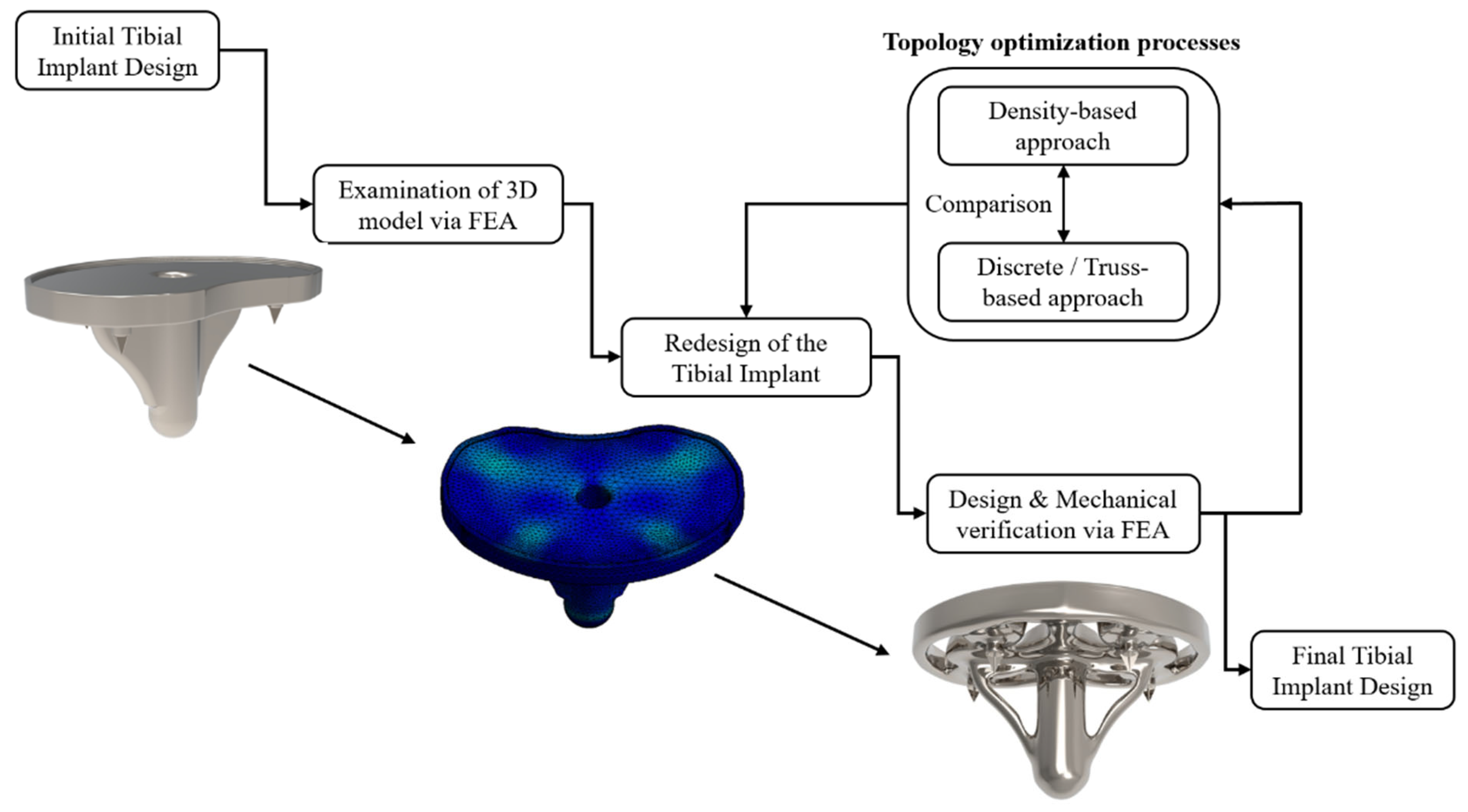
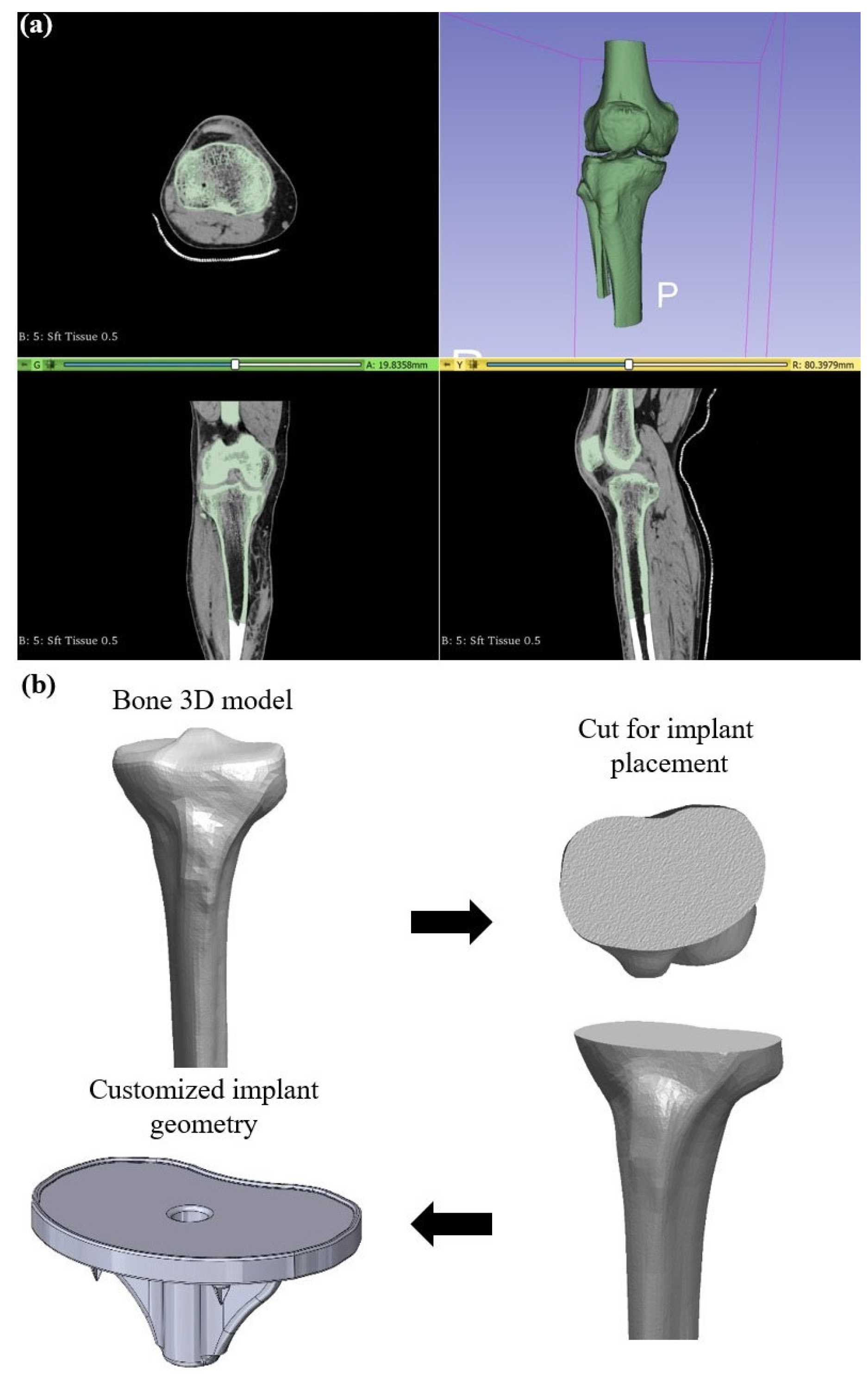
3. Design and Analysis Methodology

A customized tibial implant for a knee replacement was designed by reverse engineering the DICOM files from the patient’s CT scans. Then, the mechanical performance of the designed tibial implant was evaluated through FEA and the need for TO was highlighted. The tibial was topologically optimized with both approaches and examined in terms of mechanical response through FE analyses under realistic static loads. The outcome of the TO designs for tibial implants were compared in order to identify the most suitable TO approach for biomechanical applications. In particular, a TPMS lattice structure, which was characterized by superior mechanical behavior and higher biocompatibility performance, was employed in a customized tibial implant design, which was derived and designed based on real CT imaging data. A comparison between topology optimization via SIMP and topology optimization is then presented via lattice structures for the same object. Figure 2 depicts the workflow of the current study along with indicative images of the presented case study of the tibial implant.

4. Results and Discussion

In this section, the design of a customized tibial implant for knee replacement is presented, coupled with its TO with both approaches. Before the design phase occurs, it is essential to describe the bone structure and identify the materials utilized in such applications, along with the main hindrances that lead to an implant’s failure. The bone is a heterogeneous and anisotropic nanocomposite of which the principal components are organized hierarchically into several structural levels, from macro to the nanometer scale. The basic two regions of a human (tibia) bone are the cortical and cancellous bone. The cortical bone is almost bulk bone tissue, it is located at the external bone region, and the cancellous bone is a pore stochastic structure located in the internal bone region with porosity ranging from 50% to 90% (relative density 10% to 50%). Thus, the most crucial part of bone implant development is the material selection and structure’s configuration, which are vital to secure the robustness of the implant through time and the biocompatibility requirements. The term biocompatibility is frequently used to describe the essence of biomaterials that are used to manufacture implants without generating any unfavorable consequences on the tissue. Moreover, it is worth mentioning that biomaterials should not be toxic, immunogenic, thrombogenic, carcinogenic, or irritant. This could be achieved by eradicating as much as possible the chemical reaction with the surrounding environment. Such applications predominantly use metals and metallic alloys (titanium, titanium alloys, nickel alloys, stainless steel. and Co-Cr alloys) due to their exceptional mechanical properties. The first metals used as implants were plain carbon and vanadium steel, but they had been substituted by titanium, platinum, and magnesium alloys due to their higher biocompatibility. The metallic materials are extremely effective due to their corrosion resistance, which is mainly caused by their protective oxide layer. The metals in biomechanical applications are categorized into three generations. In the first generation of metallic biomaterials, the major purpose of them was to minimize as much as possible the toxicity. The second generation of metallic biomaterials have been arranged in order to maximize the functionality not only of the mechanical properties but also at the molecular level. In other words, the main achievement of this generation of metals was the amalgamation of the implant into the surrounding environment. The third generation of biomaterials focused on the reconstruction of the tissue around the implant [30]. The host reactions to biomaterials are highly heterogeneous, involve a variety of different mechanisms, and are influenced by factors such as cost, material, and surgical procedure characteristics.
However, there are some phenomena such as wear, osseointegration, and the stress shielding effect, which could lead to a failure of bone implants, especially those with a significant structural role (hip implant, tibial implant, etc.) [30]. In detail, wear is a process of surface interaction that results in the deformation and removal of material from the surfaces as a result of the mechanical action between the sliding faces. The life cycle of an implant is reduced dramatically due to the wear that is constantly undergoing. Wear is responsible for osteolytic reaction and loosening. The wear effect is unpredictable and simultaneously cannot be prevented. On the other hand, osseointegration, which is bone ingrowth into a metal implant, could be achieved by increasing the surface roughness and concurrently increasing the porosity of the metallic implant. Porosity in orthopedic metal implants provides primary support to tissue adhesion, growth, and vascularization [31]. Another advantageous property of porous materials for hard tissue repair is the ability to manage their elastic modulus to match that of bone, thereby reducing stress shielding issues [32]. As it is commonly known, stress-shielding phenomena occur due to the characteristic behavior of bone adapting to the loading conditions. Thus, if the implant is able to withstand and absorb higher loads, and then the bone structure degrades. The aftermath of this effect is bone loss and instability [33]. In addition to the above, the stress shielding effect could lead to osteoporosis in low-stress concertation areas [34]. Hence, with the implementation of lattice structures via topology optimization, the implants are designed in order to reduce the mechanical strength and stiffness of the structure. Moreover, the employment of a lattice structure reduces the overall stiffness of the implant, bridging the gap between the bone and the metal alloy, minimizing the stress shielding effect.

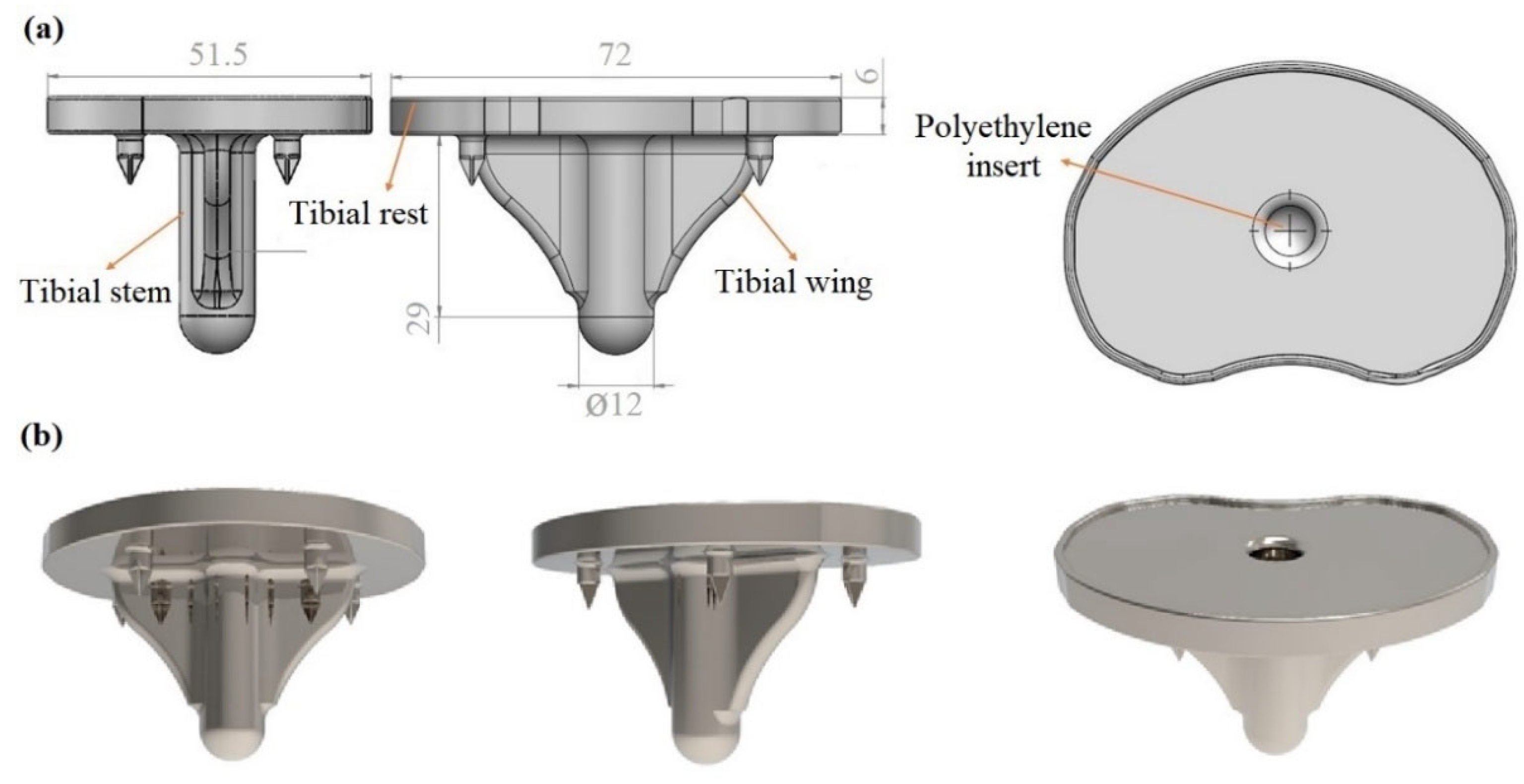
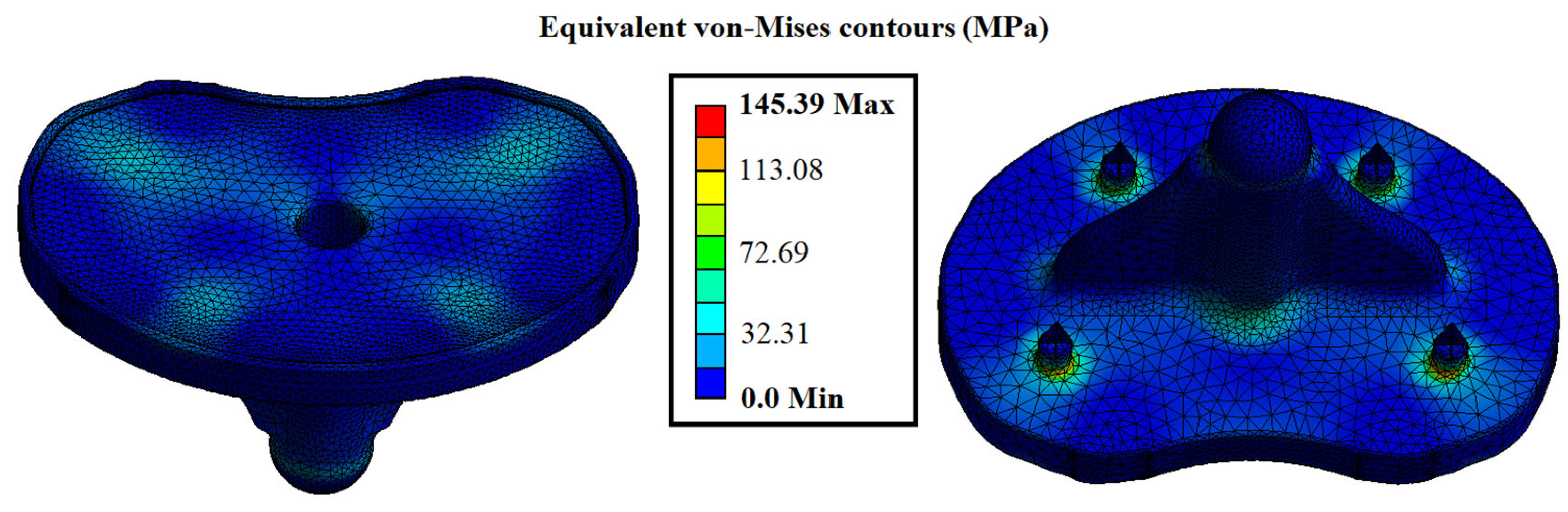
4.1. Original Design of the Tibial Implant

The first step of the development of customized implants is the extraction of detailed anatomical data from scanning techniques, such as computed tomography (CT) or magnetic resonance imaging (MRI), in order to exploit them for the design of the implant. The first part of the procedure involved gathering all of the files from a CT scan performed on the patient. The CT scan’s quality is critical for obtaining geometrical criteria as close as feasible to the original tibia. Then, the region of interest was defined and selected to retrieve the necessary geometrical data. In this case study, the tibia part of the knee joint was the region of interest for a CT scan of an adult male with 75 kg weight. Then, the acquired DICOM (Digital Imaging and Communications in Medicine) files from the abovementioned region were transformed into a 3D surface model utilizing the 3D Slicer 4.13.0 (Surgical Planning Lab, Harvard Medical School, Harvard University, Boston, MA, USA), as depicted in Figure 3a. This process was conducted by employing the proper threshold on the CT scans for bone reconstruction. After the extraction of the 3D CAD model of the whole knee joint, the next step was the isolation of the upper region of the tibia bone, which was performed by manually trimming the unnecessary elements. Then, utilizing the SolidWorks™ design software from Dassault Systems, the proper cut for the implant placement was conducted, and the customized area for the implant’s plate was exported, as it is illustrated in Figure 3b.
Having the unique geometry of the bone’s cut, the design process for the rest of the implant was performed. More specifically, the stem’s plate was designed according to the patient’s tibia cross-section. Moreover, four symmetric spikes were placed to secure the implant’s placement. In addition, a tibial stem and its corresponding wings were also developed depending on the tibia volume in order to nest inside the bone. Finally, a polyethylene insert was designed to secure the polyethylene part on the implant preventing abrasion between metal components and concurrently providing a smooth operation with the femoral part. Figure 4a illustrates the implant’s regions along with the design and basic dimensions for the developed tibial implant, and Figure 4b depicts rendered images for the designed tibial implant.
After the design of the customized tibial implant, the mechanical response of the designed implant was evaluated under realistic static loads through FEA utilizing the static structural module of the Ansys™ platform. The first step of the process was to apply the proper material to obtain the proper mechanical properties. More specifically, Inconel 718 was employed as a construction material due to its ability to withstand high mechanical loads and simultaneously tolerance in extreme environments, such as the human body. Inconel 718 is a newly suggested biomaterial, and its advantages are the high corrosion resistance and the extended life cycle, which could increase the life of the implants in certain cases (i.e., orthopedic and dental implants) compared with the current materials [35,36]. On the other hand, Inconel 718 has some biocompatibility issues that should be addressed before the implementation in a real use case, such as surface modification to reduce the Nickel ions emission [37,38]. The basic properties of the 3D-printed part constructed with Inconel 718 material are listed in Table 2, as they were derived from published studies [39]. One of the most crucial parts of a finite element analysis is the application of the proper computational mesh to the model in order to achieve mesh-independent results. After a mesh sensitivity analysis focused on the equivalent von Mises stresses, the optimal mesh was obtained with tetrahedral elements of 120,276 total and 75,320 total elements, resulting in an element size range between 1.5 mm and 2 mm.
The next step was to set the boundary conditions, such as the fixation areas, and apply the type and value of the load on the model. The loading conditions depended on the weight of the patient (which is 75 kg). In detail, the maximum load derives when intense exercises such as squatting are performed by multiplying the body weight by 7.2 times, resulting in a total force of almost 5300 N [40]. The direction of the applied force was defined as parallel with the vertical axis, and the top surface of the tibial rest was selected as the position of the force application. Regarding the fixation areas, two different types were implemented: displacement and fixed support. The displacement support was inserted on the four spikes of the component with a high friction coefficient (1.2) and fixed support on the end of the implant, constraining any rotations and displacements. After the setup of the finite element model, the analysis was conducted with 10 sub-steps in order to achieve smoother and easier convergence. To conclude, the maximum stresses were spotted around the four spikes where the fixation points were placed and secondary on the base of the tibial stem due to the compressive loads, which are inserted into the bone. The maximum value of the stress at the spikes was observed at 145 MPa and fluctuated in these regions between 145 MPa and 96 MPa. The rest of the regions showed negligible stress concentration, as depicted in Figure 5. It is worth mentioning that the factor of safety (FOS) was 7.58, indicating the necessity of topology optimization, meaning that the current design of the implant could withstand up to 7.58 times the applied loads in order to observe the failure of the structure.

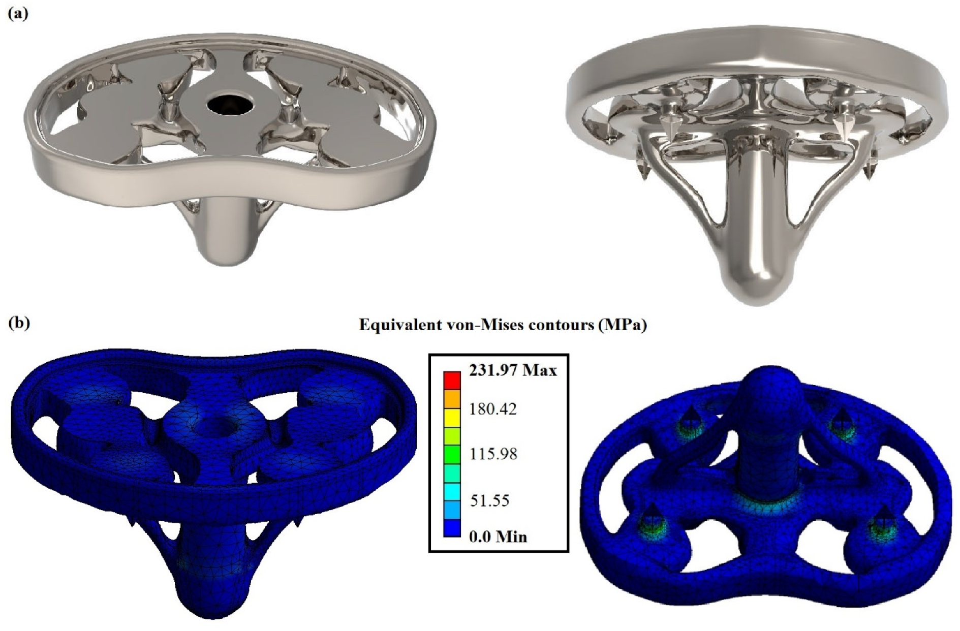
4.2. Topology Optimization of the Tibial Implant via Density-Based Approach

For the density base approach, the initial implant design was inserted coupled with the results from the aforementioned finite element analysis. The density-based topology optimization process was performed at the topology optimization module of the Ansys™ platform utilizing the SIMP algorithm. In the current optimization process, the number of iterations was set to 50, and convergence accuracy was at 2%. The next step was to define the regions that would be optimized and the exclusions regions that must remain intact due to their functionality during the optimization process. The final step was the employment of the objectives, in detail, the minimization of the mass of the implant and maintaining the maximum von Mises stress below the material’s yield strength. The boundary conditions and the mesh were the same as the FEA of the initial design.
The topology optimization was performed on the whole part, excluding the abovementioned regions, which have to remain intact, and the results are shown in Figure 6. The weight of the post-processed implant’s design has been reduced by nearly 25%, measured at 133.68 g compared to the initial weight of 177.69 g. Moreover, the factor of safety for the topology-optimized implant was evaluated at 4.74. When the original and optimized models’ finite element analysis results are compared, there is no significant difference in the values of von Mises stress. The maximum von Mises stress on the tibial implant has increased from 145.32 MPa in the original model to 231.97 MPa in the optimized model. Based on the analysis and comparison of the FEA results, it could be indicated that the topology optimization is advantageous for implant improvement by achieving a weight reduction of 25% while increasing the maximum value of von Mises stress by only 37% percent. Figure 6a,b show the implant design after the density-based TO process and the equivalent von Mises stress contour for the implant, respectively.

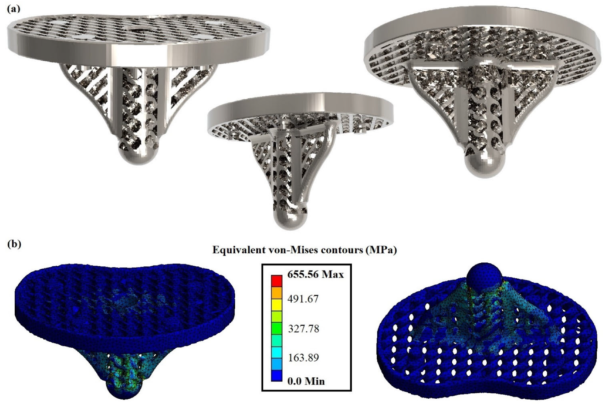
4.3. Topology Optimization of the Tibial Implant via Discrete/Truss-Based Approach

In this subsection, the TO process was performed utilizing the discrete-based approach. More specifically, some solid regions of the implant were replaced by lattice structures in order to reduce its mass and offer increased elasticity reducing the stress shielding effect. The selected architected material for this application was the Schwarz Diamond (SD) structure. This structure belongs to the TPMS architected material category and has shown one of the best mechanical performances in terms of mechanical strength, according to existing studies [16,17]. Moreover, the relative density of the applied structure was regulated at 50%, with a unit cell length at 10 mm and wall thickness at 1.75 mm. This mass reduction leads to the degradation of the structure’s properties resulting in a decrease of around 80–90% percentage of the construction material’s nominal properties, as it was showed by Al-Ketan et al. [41] with similar construction material and applied architected material. Employing this technique, the designed implant, which is constructed with a strong metal alloy, could reveal effective mechanical properties close to the bone, reducing the stress-shielding effect.
Hence, the aforementioned lattice structure was embedded in the tibial implant’s designs, as illustrated in Figure 7a. It is worth noting that some solid regions remained due to their crucial role in the functionality of the implant. In addition to the significant mass reduction, the proposed design of the implant addresses, up to a certain point, the main degradation phenomena that were aforementioned. In addition, the existence of the lattices creates rough surfaces on the external boundaries of the implant, increasing the friction coefficient and reducing the wear issue. Furthermore, the applied SD structure has a high surface area to volume ratio, which in collaboration with the high porosity, facilitates the tissue regeneration process and addresses the osseointegration issue. This provides a comprehensive advantage for biomechanical applications, such as the developed implant [9].
The FEA of the optimized implant with lattice structures differed from the previous studies due to the fact that the computational mesh was rebuilt in order to capture the unique geometry of the lattice structure. In detail, the total nodes and elements of the mesh were 151,329 and 74,058, respectively, with the size of the tetrahedral elements ranging between 1 mm and 1.2 mm. The fixations and the loading conditions remained the same with the aforementioned analyses. Figure 7b portrays the equivalent von Mises stress contours for the optimized tibial implant with lattice structures. The maximum von Mises stress was increased at 655.56 MPa, resulting in a factor of safety of 1.72. These values were observed on the base of the implant where the standard fix support was placed. To conclude, the tibial implant with the SD lattice structure withstood the applied load without exceeding the yield stress of the applied material, offering some significant advantages to the implant (lightweight, high porosity, etc.).
In Table 3, a comparison between the initial design and the designs that were derived from the two topology optimization approaches is presented in terms of mass reduction. In detail, the mass of the initial design was 177.69 g with a factor of safety above 5; after the topology optimization with a density-based approach, the mass of the developed design was reduced by 24.8% at 133.68 g with a decreased factor of safety at almost 5. Furthermore, with the implementation of the discrete-based approach, and more specifically with the employment of Schwartz’s diamond lattice structure, the mass was reduced by 45.4% from the initial design and 27.4% from the density-based design, at 97.02 g. In addition, it was observed that the final design had sufficient structural integrity with a factor safety of 1.72 indicating that it could handle almost twice the loads before it breaks. Finally, in the last column of Table 3, the values for the percentage reduction in the factor of safety are listed in order to better understand the performance of each implant. From these data can be derived that the reduction in the factor of safety is proportional to the mass reduction regardless of the applied TO process. In detail, for discrete-based TO tibial implant, both the percentages of mass and the factor of safety were almost doubled compared with the density-based TO tibial implant. However, with the discrete/truss-based approach via architected materials, a greater mass reduction percentage was achieved. This occurs due to the fact that the employed architected material could be implemented in all non-essential areas of the tibial implant’s initial design, as the architected material secures the necessary connectivity between the regions of the whole structure. On the other hand, the density-based approach removes the material’s voxel for certain non-essential regions in order to maintain the connectivity between the essential regions of the parts.

5. Conclusions

The current paper investigated the theoretical background of the topology optimization procedures and demonstrated a biomechanical use case, i.e., the processes of designing and topologically optimizing a customized tibial implant. At first, the geometric data of the patient’s tibia were extracted via CT scans and were exploited in order to design the customized tibial implant which would perfectly fit on the patient’s bone. Then, the initial design of the tibial implant was evaluated via FEA, showing an increased factor of safety at 7.58, indicating that there is a need for topology optimization and mass reduction. The initial design was topologically optimized with both approaches, namely the density-based approach and the discrete-based approach, and the optimized designs were evaluated and compared through FEA. In detail, the conductions of the finite element analyses for the three different specimens regarding the stress concertation areas, it was concluded that none of the designs exceeded the limits of the material properties. Moreover, the discrete-based approach not only reduced the mass of the implant by 45.4% but it was also added a series of physical properties that enhanced the biocompatibility and the efficiency of the implant. These properties are the high porosity of up to 50%, the high surface-area-to-volume ratio, and the high roughness of the external surfaces. The existence of porosity and increased surface-area-to-volume ratio enhance the osseointegration process, as it provides the necessary space and area for tissue regeneration and diffusion of oxygen and nutrients. On the other hand, the lattices offer more elasticity in the overall structure, reducing the stress shielding effect, and the high roughness reduces the sliding between the implant and bone, addressing the wear issue. To conclude, the discrete-based approach was validated as a superior method of topology optimization for biomechanical applications both in terms of mechanical response and biocompatibility.

Author Contributions

Conceptualization, N.K. and T.B.; methodology, N.K. and T.B.; validation, N.K., T.B. and K.T.; investigation, N.K. and T.B.; resources, K.T. and D.T.; writing—original draft preparation, N.K. and T.B.; writing—review and editing, K.T and D.T.; visualization, N.K and T.B.; supervision, K.T. and D.T.; project administration, D.T. All authors have read and agreed to the published version of the manuscript.

Funding

This research received no external funding.

Informed Consent Statement

Not applicable.

Data Availability Statement

Not applicable.

Acknowledgments

We would like to acknowledge the technical staff of the Digital Manufacturing and Materials Characterization Laboratory (DMMC Lab) of International Hellenic University for the support of this research.

Conflicts of Interest

The authors declare no conflict of interest.

References

  1. Kirsch, U. Structural Optimization Fundamentals and Applications; Springer: Berlin/Heidelberg, Germany, 1993. [Google Scholar] [CrossRef] [Green Version]
  2. Ehrgott, M. Multicriteria Optimization; Springer: Berlin/Heidelberg, Germany, 2005. [Google Scholar] [CrossRef] [Green Version]
  3. Gibson, I.; Rosen, D.W.; Stucker, B. Additive Manufacturing Technologies; Springer: New York, NY, USA, 2010. [Google Scholar] [CrossRef]
  4. Frazier, W.E. Digital manufacturing of metallic components: Vision and roadmap. In Proceedings of the 2010 International Solid Freeform Fabrication Symposium, Austin, Texas, USA, 9–11 August 2010. [Google Scholar]
  5. Kladovasilakis, N.; Charalampous, P.; Kostavelis, I.; Tzetzis, D.; Tzovaras, D. Impact of metal additive manufacturing parameters on the powder bed fusion and direct energy deposition processes: A comprehensive review. Prog. Addit. Manuf. 2021, 6, 349–365. [Google Scholar] [CrossRef]
  6. Frazier, W.E. Metal additive manufacturing: A review. J. Mater. Eng. Perform. 2014, 23, 1917–1928. [Google Scholar] [CrossRef]
  7. Tyflopoulos, E.; Flem, D.T.; Steinert, M.; Olsen, A. State of the art of generative design and topology optimization and potential research needs. In Proceedings of the NordDesign 2018, Linköping, Sweden, 14–17 August 2018. [Google Scholar]
  8. Bendsøe, M.P.; Sigmund, O. Topology Optimization: Theory, Methods, and Applications; Springer: Berlin/Heidelberg, Germany, 2003. [Google Scholar] [CrossRef]
  9. Kladovasilakis, N.; Tsongas, K.; Tzetzis, D. Finite Element Analysis of Orthopedic Hip Implant with Functionally Graded Bioinspired Lattice Structures. Biomimetics 2020, 5, 44. [Google Scholar] [CrossRef] [PubMed]
  10. Xie, Y.M.; Steven, G.P. Evolutionary Structural Optimization; Springer: London, UK, 1997. [Google Scholar] [CrossRef]
  11. Querin, O.M.; Steven, G.P.; Xie, Y.M. Evolutionary structural optimisation using an additive algorithm. Finite Elem. Anal. Des. 2000, 34, 291–308. [Google Scholar] [CrossRef]
  12. Tcherniak, D. Topology optimization of resonating structures using SIMP method. Int. J. Numer. Methods Eng. 2002, 54, 1605–1622. [Google Scholar] [CrossRef]
  13. Jiao, H.; Zhou, Q.; Fan, S.; Li, Y. A New Hybrid Topology Optimization Method Coupling ESO and SIMP Method. In Proceedings of China Modern Logistics Engineering, Lecture Notes in Electrical Engineering; Springer: Berlin/Heidelberg, Germany, 2015; 286p. [Google Scholar] [CrossRef]
  14. Gibson, L.J. Modelling the mechanical behavior of cellular materials. Mater. Sci. Eng. A 1989, 110, 1–36. [Google Scholar] [CrossRef]
  15. Gibson, L.J.; Ashby, M.F. Cellular Solids. Structure and Properties; Cambridge University Press: Cambridge, UK, 1997. [Google Scholar] [CrossRef]
  16. Kladovasilakis, N.; Tsongas, K.; Kostavelis, I.; Tzovaras, D.; Tzetzis, D. Effective Mechanical Properties of Additive Manufactured Strut-Lattice Structures: Experimental and Finite Element Study. Adv. Eng. Mater. 2021, 24, 2100879. [Google Scholar] [CrossRef]
  17. Kladovasilakis, N.; Tsongas, K.; Kostavelis, I.; Tzovaras, D.; Tzetzis, D. Effective mechanical properties of additive manufactured triply periodic minimal surfaces: Experimental and finite element study. Int. J. Adv. Manuf. Technol. 2022, 121, 7169–7189. [Google Scholar] [CrossRef]
  18. Deshpande, V.S.; Fleck, N.A.; Ashby, M.F. Effective properties of the octet-truss lattice material. J. Mech. Phys. Solids 2001, 49, 1747–1769. [Google Scholar] [CrossRef] [Green Version]
  19. Kladovasilakis, N.; Tsongas, K.; Karalekas, D.; Tzetzis, D. Architected Materials for Additive Manufacturing: A Comprehensive Review. Materials 2022, 15, 5919. [Google Scholar] [CrossRef]
  20. Pei, E.; Kabir, I.; Breški, T.; Godec, D.; Nordin, A. A review of geometric dimensioning and tolerancing (GD&T) of additive manufacturing and powder bed fusion lattices. Prog. Addit. Manuf. 2022, 7, 1297–1305. [Google Scholar] [CrossRef]
  21. Mantovani, S.; Giacalone, M.; Merulla, A.; Bassoli, E.; Defanti, S. Effective Mechanical Properties of AlSi7Mg Additively Manufactured Cubic Lattice Structures. 3D Print. Addit. Manuf. 2021, 9, 326–336. [Google Scholar] [CrossRef]
  22. Chen, Y.; Wang, Q.; Wang, C.; Gong, P.; Shi, Y.; Yu, Y.; Liu, Z. Topology Optimization Design and Experimental Research of a 3D-Printed Metal Aerospace Bracket Considering Fatigue Performance. Appl. Sci. 2021, 11, 6671. [Google Scholar] [CrossRef]
  23. Gebisa, A.W.; Lemu, H.G. A case study on topology optimized design for additive Manufacturing. IOP Conf. Ser. Mater. Sci. Eng. 2017, 276, 12026. [Google Scholar] [CrossRef] [Green Version]
  24. Li, C.; Kim, I.Y.; Jeswiet, J. Conceptual and detailed design of an automotive engine cradle by using topology, shape, and size optimization. J. Struct. Multidiscip. Optim. 2015, 51, 547–564. [Google Scholar] [CrossRef]
  25. Ferro, C.G.; Varetti, S.; De Pasquale, G.; Maggiore, P. Lattice structured impact absorber with embedded anti-icing system for aircraft wings fabricated with additive SLM process. Mater. Today Commun. 2018, 15, 185–189. [Google Scholar] [CrossRef]
  26. Fischer, S.F. Energy absorption efficiency of open-cell pure aluminum foams. Mater. Lett. 2016, 184, 208–210. [Google Scholar] [CrossRef]
  27. Wu, P.-K.; Lee, C.-W.; Sun, W.-H.; Lin, C.-L. Biomechanical Analysis and Design Method for Patient-Specific Reconstructive Implants for Large Bone Defects of the Distal Lateral Femur. Biosensors 2022, 12, 4. [Google Scholar] [CrossRef]
  28. Heinl, P.; Müller, L.; Körner, C.; Singer, R.F.; Müller, F.A. Cellular Ti–6Al–4V structures with interconnected macro porosity for bone implants fabricated by selective electron beam melting. J. Acta Biomater. 2008, 4, 1536–1544. [Google Scholar] [CrossRef]
  29. Kantaros, A.; Chatzidai, N.; Karalekas, D. 3D printing-assisted design of scaffold structures. Int. J. Adv. Manuf. Technol. 2016, 82, 559–571. [Google Scholar] [CrossRef]
  30. Murphy, W.; Black, J.; Hastings, G. Handbook of Biomaterial Properties; Springer: New York, NY, USA, 2016. [Google Scholar] [CrossRef]
  31. Bandyopadhyay, A.; Espana, F.; Balla, V.K.; Bose, S.; Ohgami, Y.; Davies, N.M. Influence of Porosity on Mechanical Properties and In vivo Response of Ti6Al4V Implants. Acta Biomater. 2010, 6, 1640–1648. [Google Scholar] [CrossRef] [PubMed] [Green Version]
  32. Arabnejad, S.; Johnston, B.; Tanzer, M.; Pasini, D. Fully porous 3D printed titanium femoral stem to reduce stress-shielding following total hip arthroplasty. J. Orthop. Res. 2017, 35, 1774–1783. [Google Scholar] [CrossRef] [PubMed] [Green Version]
  33. Kitamura, E.; Stegaroiu, R.; Nomura, S.; Miyakawa, O. Influence of marginal bone resorption on stress around an implant—A three-dimensional finite element analysis. J. Oral. Rehabil. 2005, 32, 279–286. [Google Scholar] [CrossRef] [PubMed]
  34. Kladovasilakis, N.; Charalampous, P.; Boumpakis, A.; Kontodina, T.; Tsongas, K.; Tzetzis, D.; Kostavelis, I.; Givissis, P.; Tzovaras, D. Development of biodegradable customized tibial scaffold with advanced architected materials utilizing additive manufacturing. J. Mech. Behav. Biomed. Mater. 2023, 141, 105796. [Google Scholar] [CrossRef] [PubMed]
  35. Singh, S.N.; Chowdhury, S.; Nirsanametla, Y.; Deepati, A.K.; Prakash, C.; Singh, S.; Wu, L.Y.; Zheng, H.Y.; Pruncu, C. A Comparative Analysis of Laser Additive Manufacturing of High Layer Thickness Pure Ti and Inconel 718 Alloy Materials Using Finite Element Method. Materials 2021, 14, 876. [Google Scholar] [CrossRef]
  36. Liang, X.; Liu, Z.; Wang, B. State-of-the-art of surface integrity induced by tool wear effects in machining process of titanium and nickel alloys: A review. Measurement 2019, 132, 150–181. [Google Scholar] [CrossRef]
  37. Lungu, M.V.; Sobetkii, A.; Sobetkii, A.A.; Pătroi, D.; Prioteasa, P.; Ion, I.; Negrilă, C.C.; Chifiriuc, M.C. Functional properties improvement of Ag-ZnO thin films using Inconel 600 interlayer produced by electron beam evaporation technique. Thin Solid. Films 2018, 667, 76–87. [Google Scholar] [CrossRef]
  38. Khan, M.A.; Prasad, N.R.; Krishnan, S.N.; Raja, S.K.; Jappes, J.T.W.; Duraiselvam, M. Laser-treated austenitic steel and nickel alloy for human implants. Mater. Manuf. Process. 2017, 32, 1635–1641. [Google Scholar] [CrossRef]
  39. Kladovasilakis, N.; Charalampous, P.; Tsongas, K.; Kostavelis, I.; Tzovaras, D.; Tzetzis, D. Influence of Selective Laser Melting Additive Manufacturing Parameters in Inconel 718 Superalloy. Materials 2022, 15, 1362. [Google Scholar] [CrossRef]
  40. Colic, K.; Sedmak, A.; Grbovic, A.; Tatic, U.; Sedmak, S.; Djordjevic, B. Finite element modeling of hip implant static loading. Procedia Eng. 2016, 149, 257–262. [Google Scholar] [CrossRef] [Green Version]
  41. Al-Ketan, O.; Rowshan, R.; Al-Rub, R.K.A. Topology-mechanical property relationship of 3D printed strut, skeletal, and sheet based periodic metallic cellular materials. Addit. Manuf. 2018, 19, 167–183. [Google Scholar] [CrossRef]
Figure 1. Classification of architected materials based on their geometry [19].
Technologies 11 00058 g001
Figure 2. Flowchart of the implant’s topology optimization process.
Technologies 11 00058 g002
Figure 3. (a) Indicative images from the reconstruction process in 3DSlicer; (b) Workflow of the exportation of customized implant’s geometry.
Technologies 11 00058 g003
Figure 4. (a) 3D model of the initial implant with basic dimensions; (b) Rendered images of the final implant’s design.
Technologies 11 00058 g004
Figure 5. Contours of the initial design of the tibial implant for equivalent von Mises stress.
Technologies 11 00058 g005
Figure 6. (a) Rendered images of the density-based topologically optimized tibial implant; (b) Contours of the density-based topologically optimized tibial implant for equivalent von Mises stress.
Technologies 11 00058 g006
Figure 7. (a) Rendered images of the discrete-based topologically optimized tibial implant; (b) Contours of the discrete-based topologically optimized tibial implant for equivalent von Mises stresses.
Technologies 11 00058 g007
Table 1. Additive manufacturing categories [5].
AM CategoryDefinition
Material extrusionExtrusion of material from a heated nozzle
Material JettingJetting of materials through an inkjet print-head
Binder JettingDeposition of bonding agent to material’s powder
Sheet LaminationSheets of material are bonded/welded together
Vat PhotopolymerizationSelectively curing liquid photopolymer material
Powder Bed FusionSelective thermal fusion of material’s powder
Directed Energy DepositionMelting of material that is deposited through a nozzle
Cold SprayingMaterial’s powder adheres at high-speed to the part
Table 2. Basic properties of the construction materials Inconel 718 [35].
PropertiesValues
Density (kg/m3)8190
Elastic modulus (MPa)200,000
Yield strength (MPa)1100
Poisson’s ration0.29
Table 3. Evaluation of the initial and TO tibial implants.
ComponentsMass (g)Mass Reduction PercentageFactor of Safety (FOS)FOS Reduction
Percentage
Initial tibial implant177.69-7.58-
Density-based TO tibial implant133.6824.8%4.7437.5%
Discrete-based TO tibial implant97.0245.4%1.7277.3%
Disclaimer/Publisher’s Note: The statements, opinions and data contained in all publications are solely those of the individual author(s) and contributor(s) and not of MDPI and/or the editor(s). MDPI and/or the editor(s) disclaim responsibility for any injury to people or property resulting from any ideas, methods, instructions or products referred to in the content.

