
Electrical Discharge Machining of Al2O3 Using Copper Tape and TiO2 Powder-Mixed Water Medium
 ,
,  ,
, 

Abstract
:1. Introduction
- It is commercially available and relatively safe for the personnel when working with micro-sized particles in suspension (health hazard code 1: exposure may cause only irritation with minimal residual damage, according to NFPA 704), toxic in the form of nanoparticles;
- Insoluble in water;
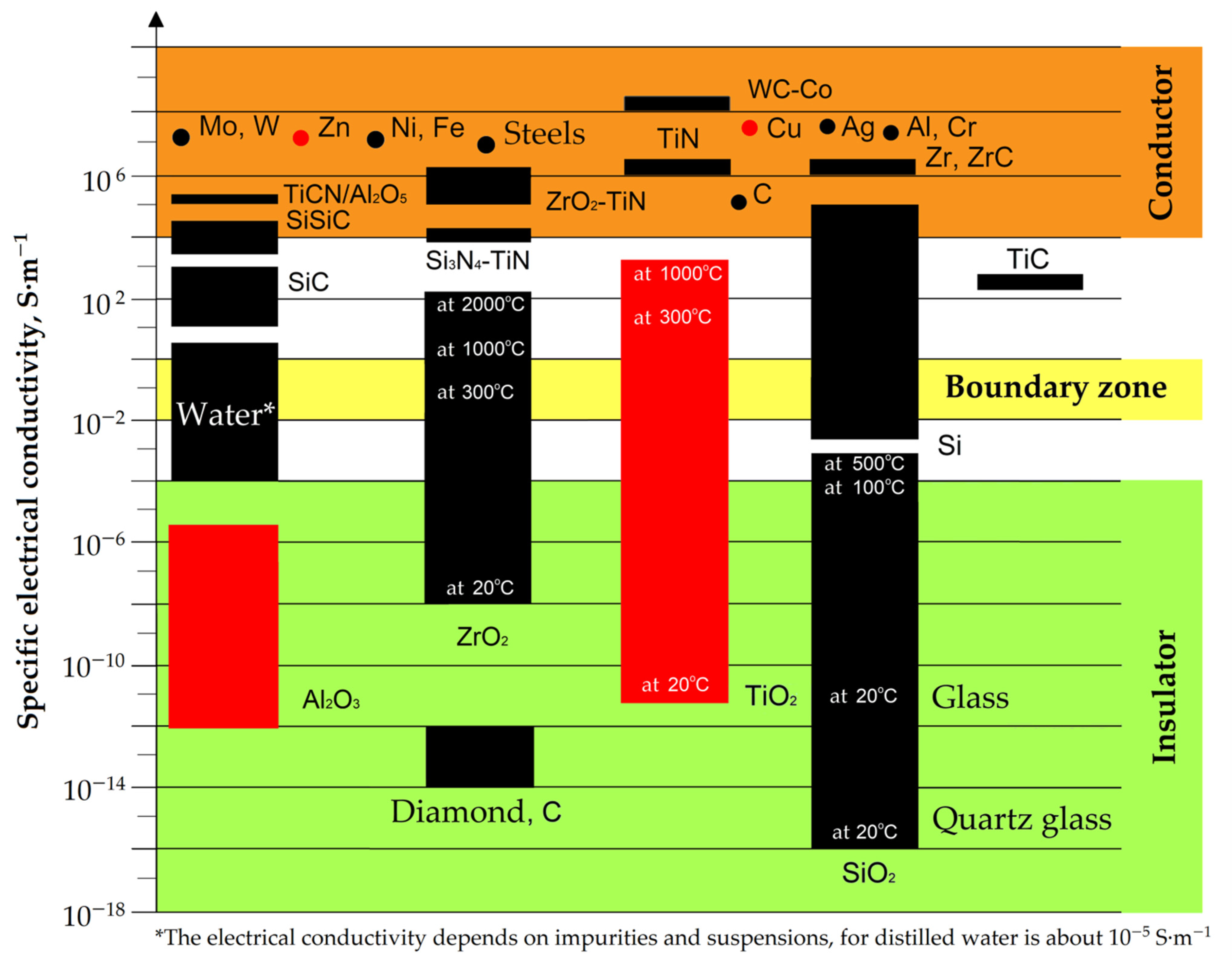
- Exhibits increased electrical conductivity to a level close to the one for conductive materials in the presence of heat (more than 1000 °C) (Figure 3);
- Transforms into rutile form when heated.
2. Materials and Methods
2.1. Sintering of the Samples
2.2. Electrical Discharge Machining
2.3. Assisting Suspension
- −
- Titanium(IV) oxide TiOx-271 grade (LLC “Titanium Investments”, Armyansk, Republic of Crimea, The Russian Federation), following GOST 9808-84, with an average particle diameter d50 = 9.29–13.94 µm.
2.4. Assisiting Electrode
3. Results
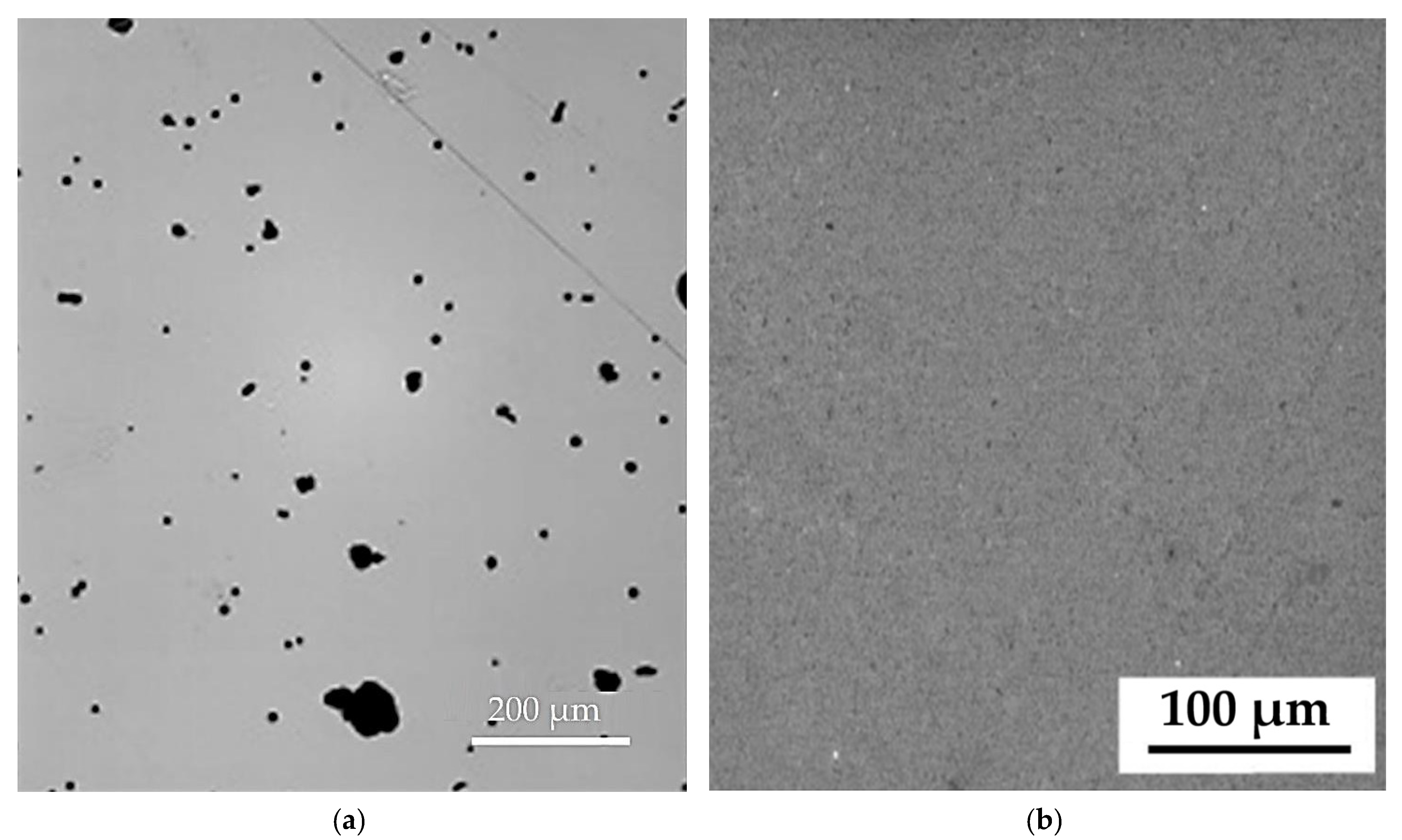
3.1. Characterization of Al2O3 Samples
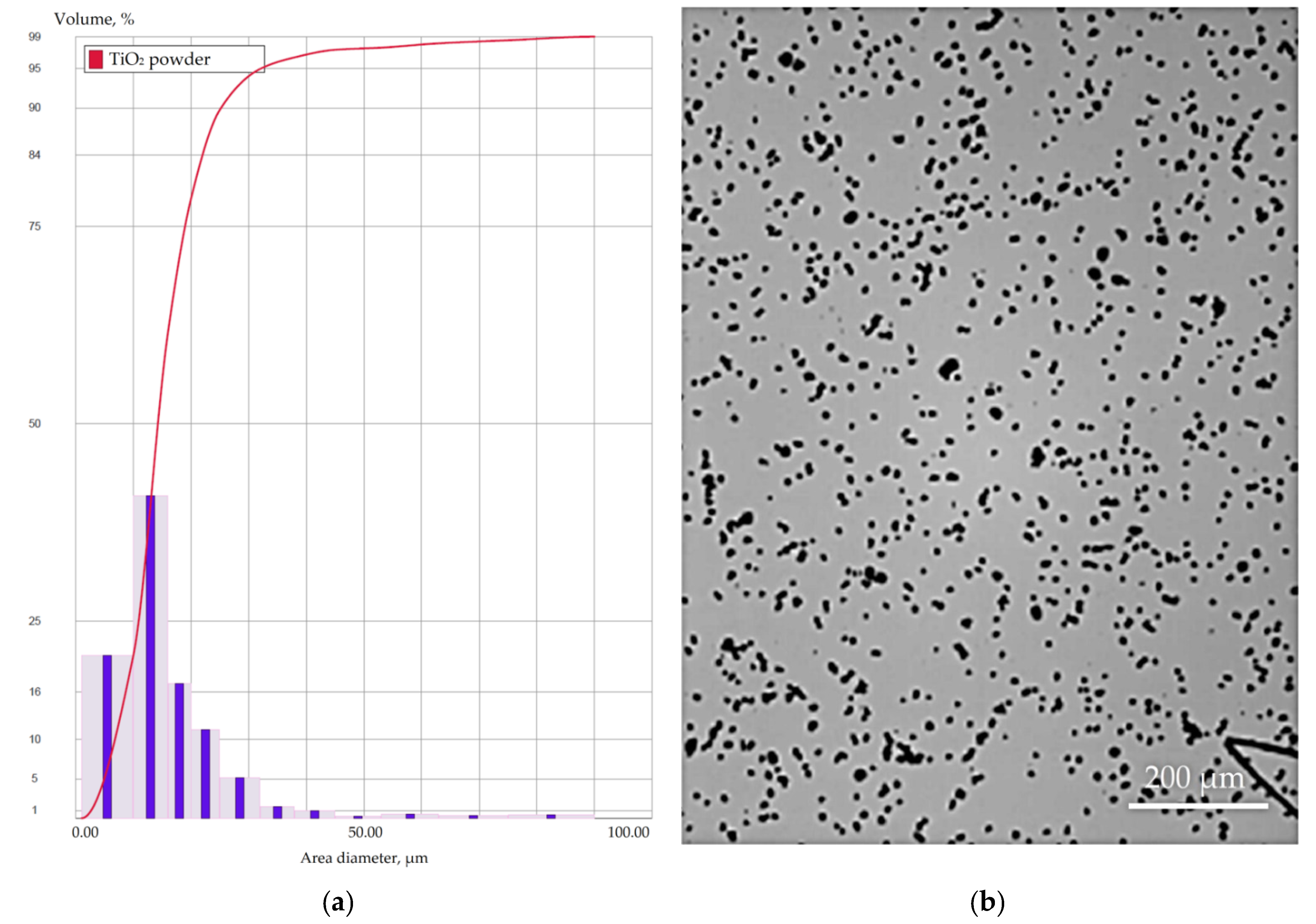
3.2. Characterization of TiO2 Powder
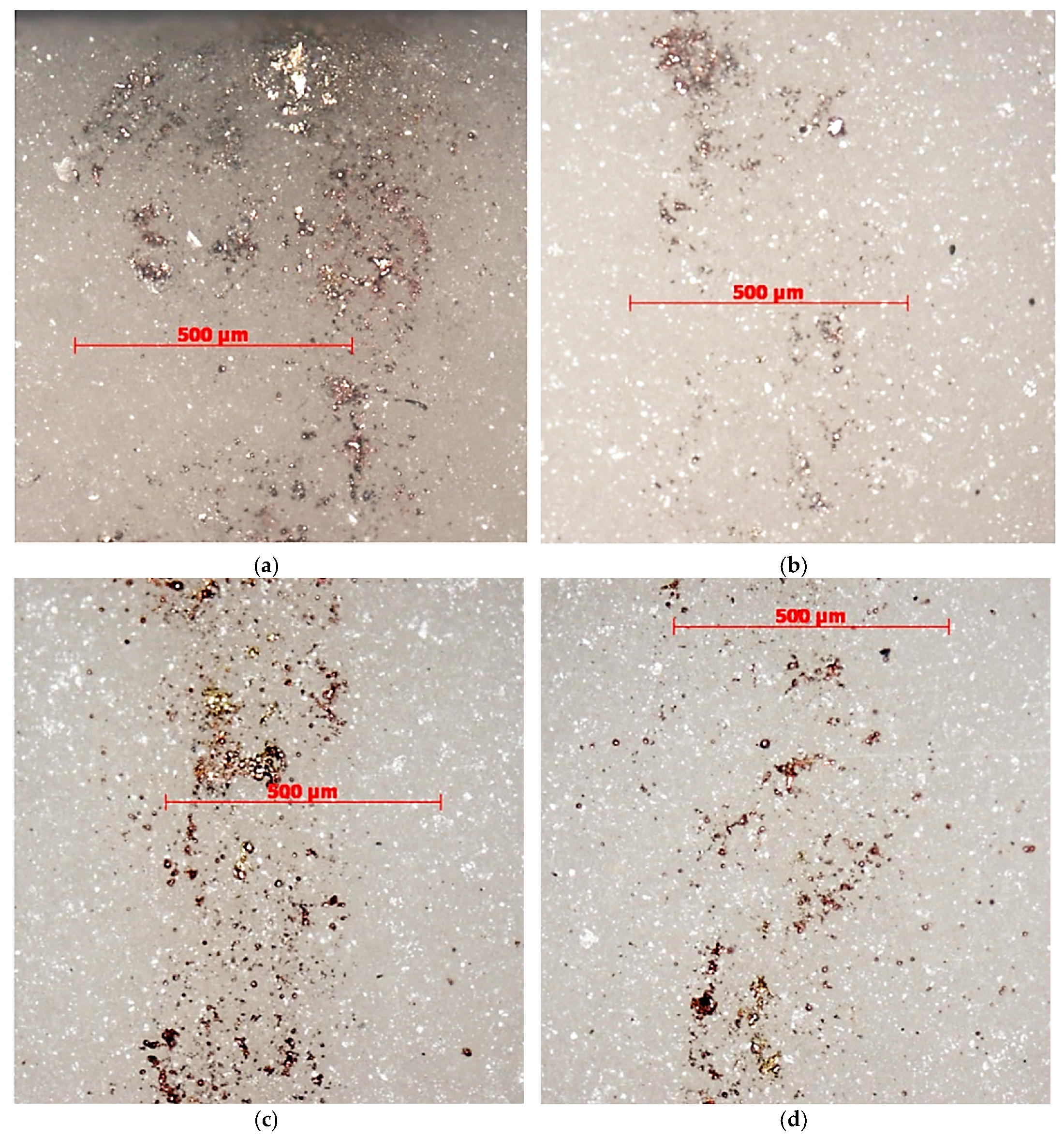
3.3. Electrical Discharge Machining in TiO2 Powder-Mixed Water Medium
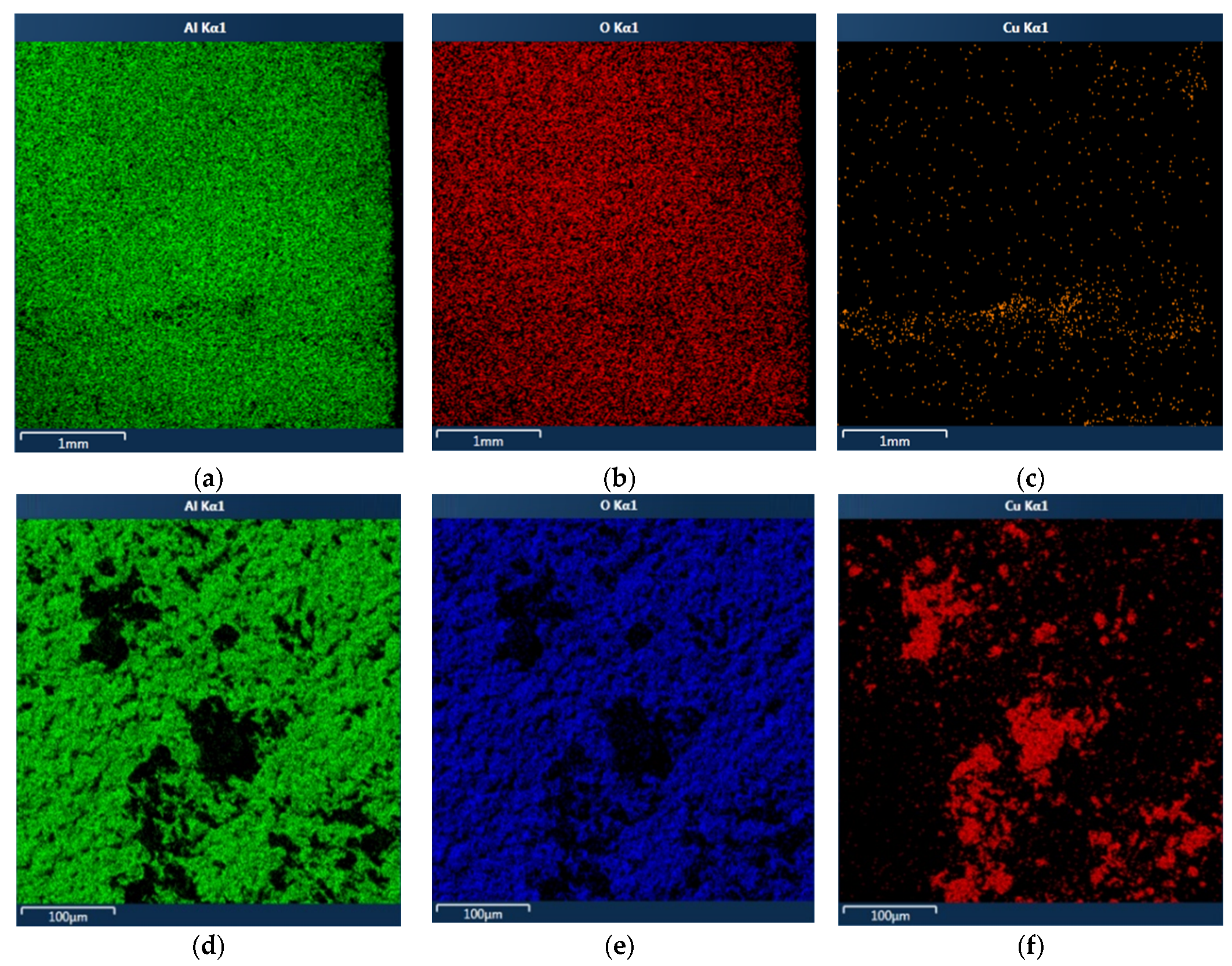
3.4. Scanning Electron Microscopy (Chemical Analyses)
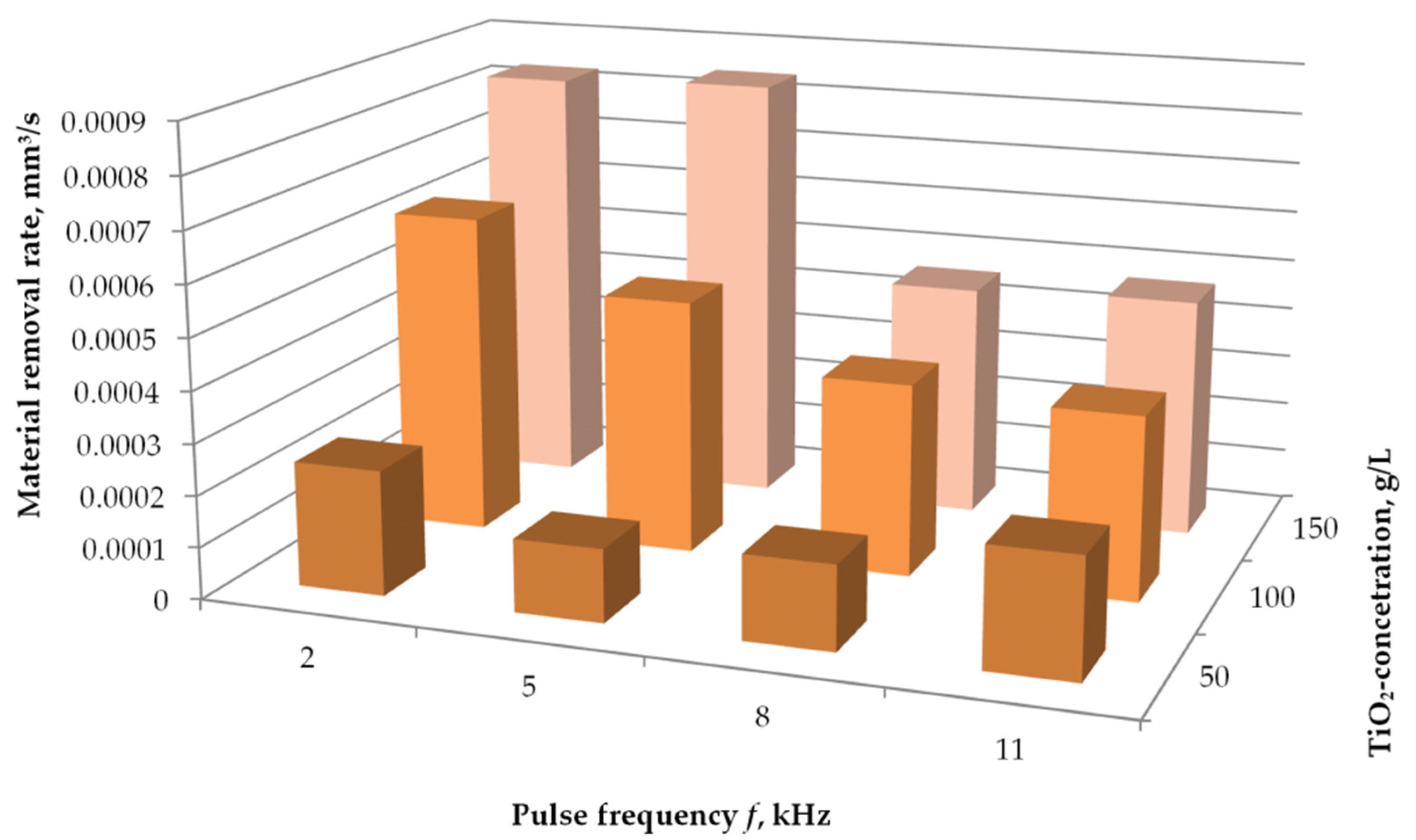
3.5. Material Removal Rate
4. Discussion
- The manufacture of a unique electrode is required;
- There is no possibility of processing ruled surfaces;
- Graphite particles exhibit electrical anisotropy (electrical properties are different in different directions of the crystal lattice) [117];
5. Conclusions
Author Contributions
Funding
Data Availability Statement
Acknowledgments
Conflicts of Interest
References
- Grigoriev, S.N.; Volosova, M.A.; Fedorov, S.V.; Okunkova, A.A.; Pivkin, P.M.; Peretyagin, P.Y.; Ershov, A. Development of DLC-Coated Solid SiAlON/TiN Ceramic End Mills for Nickel Alloy Machining: Problems and Prospects. Coatings 2021, 11, 532. [Google Scholar] [CrossRef]
- Kuzin, V.; Grigoriev, S.N.; Volosova, M.A. The role of the thermal factor in the wear mechanism of ceramic tools: Part 1. Macrolevel. J. Frict. Wear 2014, 35, 505–510. [Google Scholar] [CrossRef]
- Oppong Boakye, G.; Geambazu, L.E.; Ormsdottir, A.M.; Gunnarsson, B.G.; Csaki, I.; Fanicchia, F.; Kovalov, D.; Karlsdottir, S.N. Microstructural Properties and Wear Resistance of Fe-Cr-Co-Ni-Mo-Based High Entropy Alloy Coatings Deposited with Different Coating Techniques. Appl. Sci. 2022, 12, 3156. [Google Scholar] [CrossRef]
- Mahesh, K.; Philip, J.T.; Joshi, S.N.; Kuriachen, B. Machinability of Inconel 718: A critical review on the impact of cutting temperatures. Mater. Manuf. Process. 2021, 36, 753–791. [Google Scholar] [CrossRef]
- Stepanov, N.D.; Shaysultanov, D.G.; Chernichenko, R.S.; Tikhonovsky, M.A.; Zherebtsov, S.V. Effect of Al on structure and mechanical properties of Fe-Mn-Cr-Ni-Al non-equiatomic high entropy alloys with high Fe content. J. Alloy. Compd. 2019, 770, 194–203. [Google Scholar] [CrossRef] [Green Version]
- Padalko, A.G.; Ellert, O.G.; Efimov, N.N.; Novotortsev, V.M.; Talanova, G.V.; Zubarev, G.I.; Fedotov, V.T.; Suchkov, A.N.; Solntsev, K.A. High-pressure phase transformations, microstructure, and magnetic properties of the hypereutectic alloy 10Ni-90Al. Inorg. Mater. 2013, 49, 1098–1105. [Google Scholar] [CrossRef]
- Stepanov, N.D.; Shaysultanov, D.G.; Tikhonovsky, M.A.; Zherebtsov, S.V. Structure and high temperature mechanical properties of novel non-equiatomic Fe-(Co, Mn)-Cr-Ni-Al-(Ti) high entropy alloys. Intermetallics 2018, 102, 140–151. [Google Scholar] [CrossRef] [Green Version]
- Zhong, Q.; Wei, K.; Yue, X.; Zhou, R.; Zeng, X. Powder densification behavior and microstructure formation mechanism of W-Ni alloy processed by selective laser melting. J. Alloy. Compd. 2022, 908, 164609. [Google Scholar] [CrossRef]
- Pingale, A.D.; Belgamwar, S.U.; Rathore, J.S. A novel approach for facile synthesis of Cu-Ni/GNPs composites with excellent mechanical and tribological properties. Mater. Sci. Eng. B Solid-State Mater. Adv. Technol. 2020, 260, 114643. [Google Scholar] [CrossRef]
- Mohsan, A.U.H.; Liu, Z.; Padhy, G.K. A review on the progress towards improvement in surface integrity of Inconel 718 under high pressure and flood cooling conditions. Int. J. Adv. Manuf. Technol. 2017, 91, 107–125. [Google Scholar] [CrossRef]
- Filippov, A.V.; Tarasov, S.Y.; Podgornyh, O.A.; Shamarin, N.N.; Filippova, E.O. Oriented microtexturing on the surface of high-speed steel cutting tool. AIP Conf. Proc. 2016, 1783, 020057. [Google Scholar]
- Volosova, M.A.; Grigor′ev, S.N.; Kuzin, V.V. Effect of tinaium nitride coatings on stress structural inhomogeneity in oxide-carbide ceramic. Part 2. Concentrated force action. Refract. Ind. Ceram. 2015, 55, 487–491. [Google Scholar] [CrossRef]
- Niketh, S.; Samuel, G.L. Surface textured drill tools-an effective approach for minimizing chip evacuation force and burr formation during high aspect ratio machining of titanium alloy. J. Manuf. Sci. Eng. Trans. ASME 2021, 143, 041005. [Google Scholar] [CrossRef]
- Fedorov, S.V.; Pavlov, M.D.; Okunkova, A.A. Effect of structural and phase transformations in alloyed subsurface layer of hard-alloy tools on their wear resistance during cutting of high-temperature alloys. J. Frict. Wear 2013, 34, 190–198. [Google Scholar] [CrossRef]
- Volgin, V.M.; Lyubimov, V.V.; Kabanova, T.B.; Davydov, A.D. Theoretical analysis of micro/nano electrochemical machining with ultra-short voltage pulses. Electrochim. Acta 2021, 369, 137666. [Google Scholar] [CrossRef]
- Jiang, B.; Lan, S.; Ni, J.; Zhang, Z. Experimental investigation of spark generation in electrochemical discharge machining of non-conducting materials. J. Mater. Process. Technol. 2014, 214, 892–898. [Google Scholar] [CrossRef]
- Xie, J.; Luo, M.-J.; He, J.-L.; Liu, X.-R.; Tan, T.-W. Micro-grinding of micro-groove array on tool rake surface for dry cutting of titanium alloy. Int. J. Precis. Eng. Manuf. 2012, 13, 1845–1852. [Google Scholar] [CrossRef]
- Yusupov, Z.A. Study of Temperatures and Residual Stresses for Face Plunge-Cut Grinding of Heat-Resistant Alloys. Russ. Aeronaut. 2021, 64, 116–121. [Google Scholar] [CrossRef]
- Zheng, G.; Lin, Y. Tribological Properties of Micro-Groove Cemented Carbide by Laser Processing. Micromachines 2021, 12, 486. [Google Scholar] [CrossRef]
- Ferraris, S.; Warchomicka, F.; Barberi, J.; Cochis, A.; Scalia, A.C.; Spriano, S. Contact Guidance Effect and Prevention of Microfouling on a Beta Titanium Alloy Surface Structured by Electron-Beam Technology. Nanomaterials 2021, 11, 1474. [Google Scholar] [CrossRef]
- Wu, Z.; Deng, J.; Su, C.; Luo, C.; Xia, D. Performance of the micro-texture self-lubricating and pulsating heat pipe self-cooling tools in dry cutting process. Int. J. Refract. Met. Hard Mater. 2014, 45, 238–248. [Google Scholar] [CrossRef]
- Pakuła, D.; Staszuk, M.; Dziekońska, M.; Kožmín, P.; Čermák, A. Laser Micro-Texturing of Sintered Tool Materials Surface. Materials 2019, 12, 3152. [Google Scholar] [CrossRef] [PubMed] [Green Version]
- Vanwersch, P.; Schildermans, S.; Nagarajan, B.; Van Bael, A.; Castagne, S. Three-Dimensional Modelling of Femtosecond Laser Ablation of Metals. Lasers Manuf. Mater. Process. 2022, 9, 515–531. [Google Scholar] [CrossRef]
- Lazarenko, B.R.; Lazarenko, N.I. Electric spark machining of metals in water and electrolytes. Surf. Eng. Appl. Electrochem. 1980, 1, 5–8. [Google Scholar]
- Lazarenko, B.R.; Duradzhi, V.N.; Bryantsev, I.V. Effect of Incorporating an additional inductance on the characteristics of anode and cathode processes. Surf. Eng. Appl. Electrochem. 1979, 5, 8–13. [Google Scholar]
- Warregh, A.S.; Md Zain, M.Z. Study and analysis of micro fin deformation due to WEDM. AIP Conf. Proc. 2021, 2339, 020083. [Google Scholar]
- Lenin, N.; Sivakumar, M.; Selvakumar, G.; Rajamani, D.; Sivalingam, V.; Gupta, M.K.; Mikolajczyk, T.; Pimenov, D.Y. Optimization of Process Control Parameters for WEDM of Al-LM25/Fly Ash/B4C Hybrid Composites Using Evolutionary Algorithms: A Comparative Study. Metals 2021, 11, 1105. [Google Scholar] [CrossRef]
- Vereschaka, A.S.; Grigoriev, S.N.; Sotova, E.S.; Vereschaka, A.A. Improving the efficiency of the cutting tools made of mixed ceramics by applying modifying nano-scale multilayered coatings. Adv. Mat. Res. 2013, 712–715, 391–394. [Google Scholar]
- Vereschaka, A.A.; Grigoriev, S.N.; Volosova, M.A.; Batako, A.; Vereschaka, A.S.; Sitnikov, N.N.; Seleznev, A.E. Nano-scale multi-layered coatings for improved efficiency of ceramic cutting tools. Int. J. Adv. Manuf. Technol. 2017, 90, 27–43. [Google Scholar] [CrossRef]
- Grigoriev, S.N.; Vereschaka, A.A.; Fyodorov, S.V.; Sitnikov, N.N.; Batako, A.D. Comparative analysis of cutting properties and nature of wear of carbide cutting tools with multi-layered nano-structured and gradient coatings produced by using of various deposition methods. Int. J. Adv. Manuf. Technol. 2017, 90, 3421–3435. [Google Scholar] [CrossRef]
- Abidi, M.H.; Al-Ahmari, A.M.; Siddiquee, A.N.; Mian, S.H.; Mohammed, M.K.; Rasheed, M.S. An Investigation of the Micro-Electrical Discharge Machining of Nickel-Titanium Shape Memory Alloy Using Grey Relations Coupled with Principal Component Analysis. Metals 2017, 7, 486. [Google Scholar] [CrossRef] [Green Version]
- Lazarenko, B.R.; Mikhailov, V.V.; Gitlevich, A.E.; Verkhoturov, A.D.; Anfimov, I.S. Distribution of elements in surface layers during electric spark alloying. Surf. Eng. Appl. Electrochem. 1977, 3, 28–33. [Google Scholar]
- Ablyaz, T.R.; Shlykov, E.S.; Muratov, K.R. The Use of Electrode Tools Obtained by Selective Laser Melting to Create Textured Surfaces. Materials 2022, 15, 4885. [Google Scholar] [CrossRef] [PubMed]
- Doreswamy, D.; Bongale, A.M.; Piekarski, M.; Bongale, A.; Kumar, S.; Pimenov, D.Y.; Giasin, K.; Nadolny, K. Optimization and Modeling of Material Removal Rate in Wire-EDM of Silicon Particle Reinforced Al6061 Composite. Materials 2021, 14, 6420. [Google Scholar] [CrossRef]
- Gong, S.; Meng, F.; Sun, Y.; Su, Z.; Jin, L. Experimental study on fabricating ball micro end mill with spiral blades by low speed wire electrical discharge machining. Int. J. Adv. Manuf. Technol. 2020, 108, 2541–2558. [Google Scholar] [CrossRef]
- Volosova, M.A.; Okunkova, A.A.; Povolotskiy, D.E.; Podrabinnik, P.A. Study of electrical discharge machining for the parts of nuclear industry usage. Mech. Ind. 2015, 16, 706. [Google Scholar] [CrossRef]
- Liu, H.-D.; Xi, X.-C.; Chen, M.; Zhao, W.-S.; Chen, H. Jump Motion Planning for Shrouded Blisks Multi-Axis EDM with Short Line Segments. Procedia CIRP 2018, 68, 399–404. [Google Scholar] [CrossRef]
- Moghanizadeh, A. Reducing side overcut in EDM process by changing electrical field between tool and work piece. Int. J. Adv. Manuf. Technol. 2017, 90, 1035–1042. [Google Scholar] [CrossRef]
- Melnik, Y.A.; Kozochkin, M.P.; Porvatov, A.N.; Okunkova, A.A. On adaptive control for electrical discharge machining using vibroacoustic emission. Technologies 2018, 6, 96. [Google Scholar] [CrossRef] [Green Version]
- Grigoriev, S.N.; Kozochkin, M.P.; Kropotkina, E.Y.; Okunkova, A.A. Study of wire tool-electrode behavior during electrical discharge machining by vibroacoustic monitoring. Mech. Ind. 2016, 17, 717. [Google Scholar] [CrossRef] [Green Version]
- Mirsch, S.; Reimer, H. Preparation and electrical properties of Al—AlN—Si structures. Phys. Status Solidi A 1972, 11, 631–635. [Google Scholar] [CrossRef]
- Uemura, Y.; Tanaka, K.; Iwata, M. Some properties of thin aluminium nitride films formed in a glow discharge. Thin Solid Film. 1974, 20, 11–16. [Google Scholar] [CrossRef]
- Grigoriev, S.N.; Hamdy, K.; Volosova, M.A.; Okunkova, A.A.; Fedorov, S.V. Electrical Discharge Machining of Oxide and Nitride Ceramics: A Review. Mater. Des. 2021, 209, 109965. [Google Scholar] [CrossRef]
- Volosova, M.; Okunkova, A.; Peretyagin, P.; Melnik, Y.A.; Kapustina, N. On Electrical Discharge Machining of Non-Conductive Ceramics: A Review. Technologies 2019, 7, 55. [Google Scholar] [CrossRef] [Green Version]
- Grigoriev, S.; Pristinskiy, Y.; Volosova, M.; Fedorov, S.; Okunkova, A.; Peretyagin, P.; Smirnov, A. Wire electrical discharge machining, mechanical and tribological performance of TiN reinforced multiscale SiAlON ceramic composites fabricated by spark plasma sintering. Appl. Sci. 2021, 11, 657. [Google Scholar] [CrossRef]
- Rashid, A.; Bilal, A.; Liu, C.; Jahan, M.P.; Talamona, D.; Perveen, A. Effect of Conductive Coatings on Micro-Electro-Discharge Machinability of Aluminum Nitride Ceramic Using On-Machine-Fabricated Microelectrodes. Materials 2019, 12, 3316. [Google Scholar] [CrossRef]
- Podbolotov, K.B.; Dyatlova, E.M.; Volochko, A.T. Synthesis and reinforcement of heat-resistant cordierite-mullite ceramic structure with introduction of a fiber filler. Refract. Ind. Ceram. 2016, 57, 151–154. [Google Scholar] [CrossRef]
- Grigoriev, S.; Peretyagin, P.; Smirnov, A.; Solis, W.; Diaz, L.A.; Fernandez, A.; Torrecillas, R. Effect of graphene addition on the mechanical and electrical properties of Al2O3-SiCw ceramics. J. Eur. Ceram. Soc. 2017, 37, 2473–2479. [Google Scholar] [CrossRef]
- Grigoriev, S.N.; Volosova, M.A.; Okunkova, A.A.; Fedorov, S.V.; Hamdy, K.; Podrabinnik, P.A.; Pivkin, P.M.; Kozochkin, M.P.; Porvatov, A.N. Electrical Discharge Machining of Oxide Nanocomposite: Nanomodification of Surface and Subsurface Layers. J. Manuf. Mater. Process. 2020, 4, 96. [Google Scholar] [CrossRef]
- Liu, Y.; Guo, Y.; Wang, L.; Zhang, Y.; Feng, Y. Effects of discharge status in AE-EDM of 8YSZ ceramic. Procedia CIRP 2020, 95, 488–493. [Google Scholar] [CrossRef]
- Ji, R.; Liu, Y.; Zhang, Y.; Wang, F.; Cai, B.; Fu, X. Single discharge machining insulating Al 2O 3 stantaneous pulse energy in kerosene. Mater. Manuf. Process. 2012, 27, 676–682. [Google Scholar] [CrossRef]
- Dashuk, P.N.; Kovtun, A.V.; Lukashenko, S.V.; Sokolov, B.N. The Method of Electrical Discharge Machining of Dielectrics. SU Patent 1 542 715 A1, 15 February 1990. [Google Scholar]
- Kumar, M.; Vaishya, R.O.; Suri, N.M.; Manna, A. An Experimental Investigation of Surface Characterization for Zirconia Ceramic Using Electrochemical Discharge Machining Process. Arab. J. Sci. Eng. 2021, 46, 2269–2281. [Google Scholar] [CrossRef]
- Raju, P.; Babasaheb, S. Study on analysis of plasma resistance variation in WEDM of insulating zirconia. Mater. Manuf. Process. 2021, 36, 59–72. [Google Scholar] [CrossRef]
- Guo, Y.; Hou, P.; Shao, D.; Li, Z.; Wang, L.; Tang, L. High-Speed Wire Electrical Discharge Machining of Insulating Zirconia with a Novel Assisting Electrode. Mater. Manuf. Process. 2014, 29, 526–531. [Google Scholar] [CrossRef]
- Shinde, B.; Pawade, R. Study on analysis of kerf width variation in WEDM of insulating zirconia. Mater. Manuf. Process. 2021, 36, 1010–1018. [Google Scholar] [CrossRef]
- Hou, P.; Guo, Y.; Shao, D.; Li, Z.; Wureli, Y.; Tang, L. Influence of open-circuit voltage on high-speed wire electrical discharge machining of insulating Zirconia. Int. J. Adv. Manuf. Technol. 2014, 73, 229–239. [Google Scholar] [CrossRef]
- Kostanovskiy, A.V.; Kostanovskaya, M.E.; Zeodinov, M.G.; Pronkin, A.A. Electrical resistivity of zirconium carbide at 1200–2500 K. J. Phys. Conf. Ser. 2021, 1787, 012008. [Google Scholar] [CrossRef]
- Ordan’yan, S.S.; Zarichnyak, Y.P.; Bal’nova, E.S. Anomalous concentration dependences of thermal conductivity of ceramics in TiN-AlN and ZrC-ZrB2 systems with the structure of “eutectics of rough conglomerate”. Russ. J. Non-Ferr. Met. 2014, 55, 92–96. [Google Scholar] [CrossRef]
- Verma, S.; Satsangi, P.S.; Chattopadhyay, K.D. Enhancing process capabilities of electric discharge machining for nonconductive ceramics. Proc. Inst. Mech. Eng. Part C J. Mech. Eng. Sci. 2020, 234, 2402–2416. [Google Scholar] [CrossRef]
- Hanaoka, D.; Fukuzawa, Y.; Yamashita, K. Research of large-area electrical discharge machining for insulating Si3N4 ceramics with the assisting electrode method. Adv. Mater. Res. 2014, 939, 76–83. [Google Scholar] [CrossRef]
- Mohri, N. EDM of Advanced Ceramics—From Finish Machining to Machining Insulating Ceramics. VDI Ber. 1996, 1276, 289–296. [Google Scholar]
- Muttamara, A.; Fukuzawa, Y.; Mohri, N.; Tani, T. Effects of structural orientation on EDM properties of sapphire. Mater. Trans. 2004, 45, 2486–2488. [Google Scholar] [CrossRef] [Green Version]
- Li, X.; Liu, Y.; Yu, L.; Ji, R. Effects of electrical parameters on electrical discharge grinding of non-conductive engineering ceramics. IET Conf. Publ. 2006, 524, 1306–1309. [Google Scholar] [CrossRef]
- Moudood, M.A.; Sabur, A.; Ali, M.Y.; Jaafar, I.H. Effect of Peak Current on Material Removal Rate for Electrical Discharge Machining of Non-Conductive Al2O3 Ceramic. Adv. Mater. Res. 2014, 845, 730–734. [Google Scholar] [CrossRef]
- Kucukturk, G.; Cogun, C. A New Method for Machining of Electrically Nonconductive Workpieces Using Electric Discharge Machining Technique. Mach. Sci. Technol. 2010, 14, 189–207. [Google Scholar] [CrossRef]
- Santos-Beltrán, A.; Gallegos-Orozco, V.; Estrada-Guel, I.; Bejar-Gómez, L.; Espinosa-Magaña, F.; Miki-Yoshida, M.; Martínez-Sánchez, R. TEM characterization of Al-C-Cu-Al2O3 composites produced by mechanical milling. J. Alloy. Compd. 2007, 434–435, 514–517. [Google Scholar] [CrossRef]
- Volosova, M.A.; Okunkova, A.A.; Fedorov, S.V.; Hamdy, K.; Mikhailova, M.A. Electrical Discharge Machining Non-Conductive Ceramics: Combination of Materials. Technologies 2020, 8, 32. [Google Scholar] [CrossRef]
- Vozniakovskii, A.A.; Kidalov, S.V.; Kol’tsova, T.S. Development of composite material aluminum-carbon nanotubes with high hardness and controlled thermal conductivity. J. Compos. Mater. 2019, 53, 2959–2965. [Google Scholar] [CrossRef]
- Yuan, H.; Zhu, F.; Yang, B.; Xu, B.; Dai, Y. Latest progress in aluminum production by alumina carbothermic reduction in vacuum. Zhenkong Kexue Yu Jishu Xuebao/J. Vac. Sci. Technol. 2011, 31, 765–774. [Google Scholar]
- Chaudhari, R.; Prajapati, P.; Khanna, S.; Vora, J.; Patel, V.K.; Pimenov, D.Y.; Giasin, K. Multi-Response Optimization of Al2O3 Nanopowder-Mixed Wire Electrical Discharge Machining Process Parameters of Nitinol Shape Memory Alloy. Materials 2022, 15, 2018. [Google Scholar] [CrossRef]
- Ilani, M.A.; Khoshnevisan, M. An evaluation of the surface integrity and corrosion behavior of Ti-6Al-4 V processed thermodynamically by PM-EDM criteria. Int. J. Adv. Manuf. Technol. 2022, 120, 5117–5129. [Google Scholar] [CrossRef]
- Sabur, A.; Mohammed Mehdi, S.; Ali, M.Y.; Maleque, M.A.; Moudood, A. Investigation of Surface Roughness in Micro-EDM of Nonconductive ZrO2 Ceramic with Powder Mixed Dielectric Fluid. Adv. Mater. Res. 2016, 1115, 16–19. [Google Scholar] [CrossRef]
- Wilkenhoener, R.; Buchkremer, H.P.; Stoever, D.; Stolten, D.; Koch, A. Heat-resistant, electrically conducting joint between ceramic end plates and metallic conductors in solid oxide fuel cell. Mater. Res. Soc. Symp.-Proc. 1999, 575, 295–302. [Google Scholar] [CrossRef]
- Pratas, S.; Silva, E.L.; Neto, M.A.; Fernandes, C.M.; Fernandes, A.J.S.; Figueiredo, D.; Silva, R.F. Boron Doped Diamond for Real-Time Wireless Cutting Temperature Monitoring of Diamond Coated Carbide Tools. Materials 2021, 14, 7334. [Google Scholar] [CrossRef] [PubMed]
- Funke, V.F.; Yudkovskii, S.I.; Panov, V.S. Investigation of the physical properties and structure of TiC-WC-Co alloys. Sov. Powder Metall. Met. Ceram. 1962, 1, 449–454. [Google Scholar] [CrossRef]
- Pyachin, S.A.; Burkov, A.A.; Makarevich, K.S.; Zaitsev, A.V.; Karpovich, N.F.; Ermakov, M.A. Optical characteristics of particles produced using electroerosion dispersion of titanium in hydrogen peroxide. Tech. Phys. 2016, 61, 1046–1052. [Google Scholar] [CrossRef]
- Sahu, A.K.; Chatterjee, S.; Nayak, P.K.; Mahapatra, S.S. Study on effect of tool electrodes on surface finish during electrical discharge machining of Nitinol. IOP Conf. Ser. Mate. Sci. Eng. 2018, 338, 012033. [Google Scholar] [CrossRef] [Green Version]
- Movchan, B.A.; Grechanyuk, N.I. Microhardness and microbrittleness of condensates of the TiC-Al2O3 system. Inorg. Mater. 1981, 17, 972–973. [Google Scholar]
- Okunkova, A.A.; Volosova, M.A.; Kropotkina, E.Y.; Hamdy, K.; Grigoriev, S.N. Electrical Discharge Machining of Alumina Using Ni-Cr Coating and SnO Powder-Mixed Dielectric Medium. Metals 2022, 12, 1749. [Google Scholar] [CrossRef]
- Grigor′ev, S.N.; Fedorov, S.V.; Pavlov, M.D.; Okun’kova, A.A.; So, Y.M. Complex surface modification of carbide tool by Nb + Hf + Ti alloying followed by hardfacing (Ti + Al)N. J. Frict. Wear 2013, 34, 14–18. [Google Scholar] [CrossRef]
- Grigoriev, S.; Volosova, M.; Fyodorov, S.; Lyakhovetskiy, M.; Seleznev, A. DLC-coating application to improve the durability of ceramic tools. J. Mater. Eng. Perform. 2019, 28, 4415–4426. [Google Scholar] [CrossRef]
- Volosova, M.; Grigoriev, S.; Metel, A.; Shein, A. The role of thin-film vacuum-plasma coatings and their influence on the efficiency of ceramic cutting inserts. Coatings 2018, 8, 287. [Google Scholar] [CrossRef] [Green Version]
- Grigoriev, S.N.; Gurin, V.D.; Volosova, M.A.; Cherkasova, N.Y. Development of residual cutting tool life prediction algorithm by processing on CNC machine tool. Mater. Werkst. 2013, 44, 790–796. [Google Scholar] [CrossRef]
- Grigoriev, S.N.; Kozochkin, M.P.; Sabirov, F.S.; Kutin, A.A. Diagnostic systems as basis for technological improvement. Proc. CIRP 2012, 1, 599–604. [Google Scholar] [CrossRef] [Green Version]
- Grigoriev, S.N.; Sinopalnikov, V.A.; Tereshin, M.V.; Gurin, V.D. Control of parameters of the cutting process on the basis of diagnostics of the machine tool and workpiece. Meas. Tech. 2012, 55, 555–558. [Google Scholar] [CrossRef]
- Viswanathan, V.; Laha, T.; Balani, K.; Agarwal, A.; Seal, S. Challenges and advances in nanocomposite processing techniques. Mater. Sci. Eng. R 2006, 54, 121–285. [Google Scholar] [CrossRef]
- Wang, L.; Zhang, J.; Jiang, W. Recent development in reactive synthesis of nanostructured bulk materials by spark plasma sintering. Int. J. Refract. Met. Hard Mater. 2013, 39, 103–112. [Google Scholar] [CrossRef]
- Zhang, Y.F.; Wang, L.J.; Jiang, W.; Chen, L.-D. Microstructure and properties of Al2O3-TiC composites fabricated by combination of high-energy ball milling and spark plasma sintering (SPS). J. Inorg. Mater. 2005, 20, 1445. [Google Scholar]
- Grigoriev, S.N.; Volosova, M.A.; Okunkova, A.A.; Fedorov, S.V.; Hamdy, K.; Podrabinnik, P.A.; Pivkin, P.M.; Kozochkin, M.P.; Porvatov, A.N. Wire Tool Electrode Behavior and Wear under Discharge Pulses. Technologies 2020, 8, 49. [Google Scholar] [CrossRef]
- Grigoriev, S.N.; Kozochkin, M.P.; Porvatov, A.N.; Volosova, M.A.; Okunkova, A.A. Electrical discharge machining of ceramic nanocomposites: Sublimation phenomena and adaptive control. Heliyon 2019, 5, e02629. [Google Scholar] [CrossRef]
- Ay, M.; Etyemez, A. Optimization of the effects of wire EDM parameters on tolerances. Emerg. Mater. Res. 2020, 9, 527–531. [Google Scholar] [CrossRef]
- Markopoulos, A.P.; Papazoglou, E.-L.; Karmiris-Obratański, P. Experimental Study on the Influence of Machining Conditions on the Quality of Electrical Discharge Machined Surfaces of aluminum alloy Al5052. Machines 2020, 8, 12. [Google Scholar] [CrossRef] [Green Version]
- Moghaddam, M.A.; Kolahan, F. An optimised back propagation neural network approach and simulated annealing algorithm towards optimisation of EDM process parameters. Int. J. Manuf. Res. 2015, 10, 215–236. [Google Scholar] [CrossRef] [Green Version]
- Grigoriev, S.N.; Volosova, M.A.; Okunkova, A.A.; Fedorov, S.V.; Hamdy, K.; Podrabinnik, P.A. Elemental and Thermochemical Analyses of Materials after Electrical Discharge Machining in Water: Focus on Ni and Zn. Materials 2021, 14, 3189. [Google Scholar] [CrossRef] [PubMed]
- Grigoriev, S.N.; Teleshevskii, V.I. Measurement Problems in Technological Shaping Processes. Meas. Tech. 2011, 54, 744–749. [Google Scholar] [CrossRef]
- Li, Y.; Zheng, G.; Cheng, X.; Yang, X.; Xu, R.; Zhang, H. Cutting performance evaluation of the coated tools in high-speed milling of AISI 4340 steel. Materials 2019, 12, 3266. [Google Scholar] [CrossRef] [PubMed] [Green Version]
- Zakharov, O.V.; Brzhozovskii, B.M. Accuracy of centering during measurement by roundness gauges. Meas. Tech. 2006, 49, 1094–1097. [Google Scholar] [CrossRef]
- Rezchikov, A.F.; Kochetkov, A.V.; Zakharov, O.V. Mathematical models for estimating the degree of influence of major factors on performance and accuracy of coordinate measuring machines. MATEC Web Conf. 2017, 129, 01054. [Google Scholar] [CrossRef] [Green Version]
- Zakharov, O.V.; Balaev, A.F.; Kochetkov, A.V. Modeling Optimal Path of Touch Sensor of Coordinate Measuring Machine Based on Traveling Salesman Problem Solution. Procedia Eng. 2017, 206, 1458–1463. [Google Scholar] [CrossRef]
- Grigoriev, S.N.; Volosova, M.A.; Okunkova, A.A.; Fedorov, S.V.; Hamdy, K.; Podrabinnik, P.A. Sub-Microstructure of Surface and Subsurface Layers after Electrical Discharge Machining Structural Materials in Water. Metals 2021, 11, 1040. [Google Scholar] [CrossRef]
- Fukuzawa, Y.; Tani, T.; Mohri, N. Machining characteristics of insulated Si3N4 ceramics by electrical discharge method—Use of powder-mixed machining fluid. J. Ceram. Soc. Jpn. 2000, 108, 184–190. [Google Scholar] [CrossRef] [Green Version]
- Zhang, W.; Li, L.; Wang, N.; Teng, Y.L. Machining of 7Cr13Mo steel by US-PMEDM process. Mater. Manuf. Process. 2021, 9, 1060–1066. [Google Scholar] [CrossRef]
- Calka, A.; Wexler, D. Mechanical milling assisted by electrical discharge. Nature 2002, 419, 147–151. [Google Scholar] [CrossRef] [PubMed]
- Kumar, A.; Mandal, A.; Dixit, A.R.; Das, A.K. Performance evaluation of Al2O3 nano powder mixed dielectric for electric discharge machining of Inconel 825. Mater. Manuf. Process. 2018, 33, 986–995. [Google Scholar] [CrossRef]
- Tzeng, Y.F.; Lee, C.Y. Effects of powder characteristics on electrodischarge machining efficiency. Int. J. Adv. Manuf. Technol. 2001, 17, 586–592. [Google Scholar] [CrossRef]
- Liu, Y.H.; Li, X.P.; Ji, R.J.; Yu, L.L.; Zhang, H.F.; Li, Q.Y. Effect of technological parameter on the process performance for electric discharge milling of insulating Al2O3 ceramic. J. Mater. Process. Technol. 2008, 208, 245–250. [Google Scholar] [CrossRef]
- Lin, Y.-J.; Lin, Y.-C.; Wang, A.-C.; Wang, D.A.; Chow, H.M. Machining characteristics of EDM for non-conductive ceramics using adherent copper foils. In Advanced Materials Research, Materials Processing Technologies, Proceedings of the International Conference on Advances in Materials and Manufacturing Processes, Shenzhen, China, 6–8 November 2010; Jiang, Z.Y., Liu, X.H., Bu, J.L., Eds.; Trans Tech Publications Ltd.: Durnten-Zurich, Switzerland, 2010. [Google Scholar] [CrossRef]
- Panova, T.V.; Kovivchak, V.S. Formation of Oxide Layers on the Surface of Copper and its Alloys Modified by a High-Power Ion Beam. J. Surf. Invest. 2019, 13, 1098–1102. [Google Scholar] [CrossRef]
- Murzin, S.P.; Kryuchkov, A.N. Formation of ZnO/CuO heterostructure caused by laser-induced vibration action. Procedia Eng. 2017, 176, 546–551. [Google Scholar] [CrossRef]
- Silva, N.; Ramírez, S.; Díaz, I.; Garcia, A.; Hassan, N. Easy, Quick, and Reproducible Sonochemical Synthesis of CuO Nanoparticles. Materials 2019, 12, 804. [Google Scholar] [CrossRef]
- Zheng, W.; Chen, Y.; Peng, X.; Zhong, K.; Lin, Y.; Huang, Z. The Phase Evolution and Physical Properties of Binary Copper Oxide Thin Films Prepared by Reactive Magnetron Sputtering. Materials 2018, 11, 1253. [Google Scholar] [CrossRef] [Green Version]
- Ikim, M.I.; Spiridonova, E.Y.; Belysheva, T.V.; Gromov, V.F.; Gerasimov, G.N.; Trakhtenberg, L.I. Structural properties of metal oxide nanocomposites: Effect of preparation method. Russ. J. Phys. Chem. B 2016, 10, 543–546. [Google Scholar] [CrossRef]
- Alkan, G.; Rudolf, R.; Bogovic, J.; Jenko, D.; Friedrich, B. Structure and Formation Model of Ag/TiO2 and Au/TiO2 Nanoparticles Synthesized through Ultrasonic Spray Pyrolysis. Metals 2017, 7, 389. [Google Scholar] [CrossRef] [Green Version]
- Saikova, S.; Pavlikov, A.; Trofimova, T.; Mikhlin, Y.; Karpov, D.; Asanova, A.; Grigoriev, Y.; Volochaev, M.; Samoilo, A.; Zharkov, S.; et al. Hybrid Nanoparticles Based on Cobalt Ferrite and Gold: Preparation and Characterization. Metals 2021, 11, 705. [Google Scholar] [CrossRef]
- Grigoriev, S.; Volosova, M.; Vereschaka, A.; Sitnikov, N.; Milovich, F.; Bublikov, J.; Fyodorov, S.; Seleznev, A. Properties of (Cr,Al,Si)N-(DLC-Si) composite coatings deposited on a cutting ceramic substrate. Ceram. Int. 2020, 46, 18241–18255. [Google Scholar] [CrossRef]
- Guo, Y.; Zhu, T.; Zheng, J. Numerical simulation of electrical conductivity on the graphite-quartz model and its geophysical application. Acta Geophys. Sin. 2021, 64, 4031–4042. [Google Scholar]
- Khvostov, V.V.; Khrustachev, I.K.; Minnebaev, K.F.; Zykova, E.Y.; Yurasova, V.E. Secondary particle emission from semiconductor crystals. Vacuum 2014, 100, 84–86. [Google Scholar] [CrossRef]
- Galashev, A.E.; Ivanichkina, K.A.; Vorob’ev, A.S. Study of the Thermal Stability of a Monolayer SnS2 Film on a Graphite Substrate. High Temp. 2021, 59, 66–72. [Google Scholar] [CrossRef]
- Torres-Rojas, R.M.; Contreras-Solorio, D.A.; Hernández, L.; Enciso, A. Band gap variation in bi, tri and few-layered 2D graphene/hBN heterostructures. Solid State Commun. 2022, 341, 114553. [Google Scholar] [CrossRef]


| Parameters | Value and Description |
|---|---|
| Max axis motions X × Y × Z, mm | 125 × 200 × 80 |
| Tool positioning accuracy, µm | ±1 |
| Average surface roughness parameter Ra, µm | 0.6 |
| Dielectric medium | Any |
| Max power consumption, kW | <6 |
| Factor | Measuring Units | Value |
|---|---|---|
| Operational voltage, VO | V | 108 |
| Pulse frequency, f | kHz | 2; 5; 8; 11 |
| Pulse duration, D | µs | 1 |
| Rewinding speed, vW | m/min | 7 |
| Feed rate, vF | mm/min | 0.3 |
| Wire tension FT | N | 0.25 |
| Parameter | Value |
|---|---|
| Thickness of copper basis, mm | 0.035 ± 0.0002 |
| Tensile strength, N/cm | 115 |
| Elongation (Extension ratio), % | <2 |
| Specific electrical resistivity, Ω∙mm2∙m−1 | 0.016–0.017 |
| Operating temperature, °C | from −40 to +110 with a tolerance of ±5 |
| Tape width, mm | 10 |
| Assisting Coating | Electrical Conductivity 1, Sm∙cm−1 | Specific Electrical Resistivity 2, Ω∙mm2∙m−1 |
|---|---|---|
| Copper tape, resin-based adhesive | 0.580046 ± 0.00001 | 0.01724 × 10⁻⁶ |
| Graphite 3 | - | 8.00 |
| Distilled water 3 | - | 103 ÷ 104 |
| Inner Diameter Range, µm | Volume, % | Cumulative Volume, % |
|---|---|---|
| 1.00–10.00 | 20.82 | 20.82 |
| 10.00–16.00 | 41.22 | 62.04 |
| 16.00–20.00 | 17.25 | 79.29 |
| 20.00–25.00 | 11.36 | 90.65 |
| 25.00–32.00 | 5.23 | 95.88 |
| 32.00–38.00 | 1.48 | 97.36 |
| 38.00–45.00 | 0.97 | 98.33 |
| 45.00–53.00 | 0.27 | 98.60 |
| 53.00–63.00 | 0.56 | 99.15 |
| 63.00–75.00 | 0.39 | 99.54 |
| 75.00–90.00 | 0.46 | 100.00 |
| Chemical Elements, wt % | |||||
|---|---|---|---|---|---|
| Al | O | Cu | Zn | Ti | C |
| 0.5 | 6.0 | 81.1 | 2.6 | 1.5 | 8.3 |
| TiO2 Concentration, g/L | Pulse Frequency f, kHz | Kerf Depth h, µm | Kerf Width w. µm | Kerf Length l. µm | Angle of Segment in Plan α, Rad |
|---|---|---|---|---|---|
| 50 | 2 | 26.75 | 155.93 | 2950.00 | 0.56 |
| 5 | 33.27 | 155.93 | 1600.00 | 0.62 | |
| 8 | 26.53 | 140.03 | 2000.00 | 0.56 | |
| 11 | 23.93 | 129.55 | 3000.00 | 0.53 | |
| 100 | 2 | 51.50 | 149.19 | 5550.00 | 0.78 |
| 5 | 37.52 | 143.07 | 5100.00 | 0.67 | |
| 8 | 22.87 | 124.38 | 5550.00 | 0.50 | |
| 11 | 36.91 | 140.40 | 3800.00 | 0.66 | |
| 150 | 2 | 56.70 | 181.70 | 6750.00 | 0.83 |
| 5 | 51.61 | 111.46 | 7250.00 | 0.79 | |
| 8 | 33.17 | 138.13 | 5000.00 | 0.63 | |
| 11 | 36.64 | 145.89 | 7000.00 | 0.59 |
| TiO2 Concentration, g/L | Pulse Frequency f, kHz | Kerf Area in Plan S, mm² | Volume of Removed Material V, mm3 | Estimated Machining Time t, s | Volumetric Material Removal Rate, mm³/s |
|---|---|---|---|---|---|
| 50 | 2 | 0.00044 | 0.00130 | 5.35 | 0.00024 |
| 5 | 0.00059 | 0.00094 | 6.65 | 0.00014 | |
| 8 | 0.00043 | 0.00087 | 5.31 | 0.00016 | |
| 11 | 0.00037 | 0.00111 | 4.79 | 0.00023 | |
| 100 | 2 | 0.00116 | 0.00646 | 10.30 | 0.00063 |
| 5 | 0.00073 | 0.00373 | 7.50 | 0.00050 | |
| 8 | 0.00031 | 0.00172 | 4.57 | 0.00038 | |
| 11 | 0.00070 | 0.00265 | 7.38 | 0.00036 | |
| 150 | 2 | 0.00140 | 0.00942 | 11.34 | 0.00083 |
| 5 | 0.00120 | 0.00870 | 10.32 | 0.00084 | |
| 8 | 0.00061 | 0.00304 | 6.63 | 0.00046 | |
| 11 | 0.00049 | 0.00344 | 7.33 | 0.00047 |
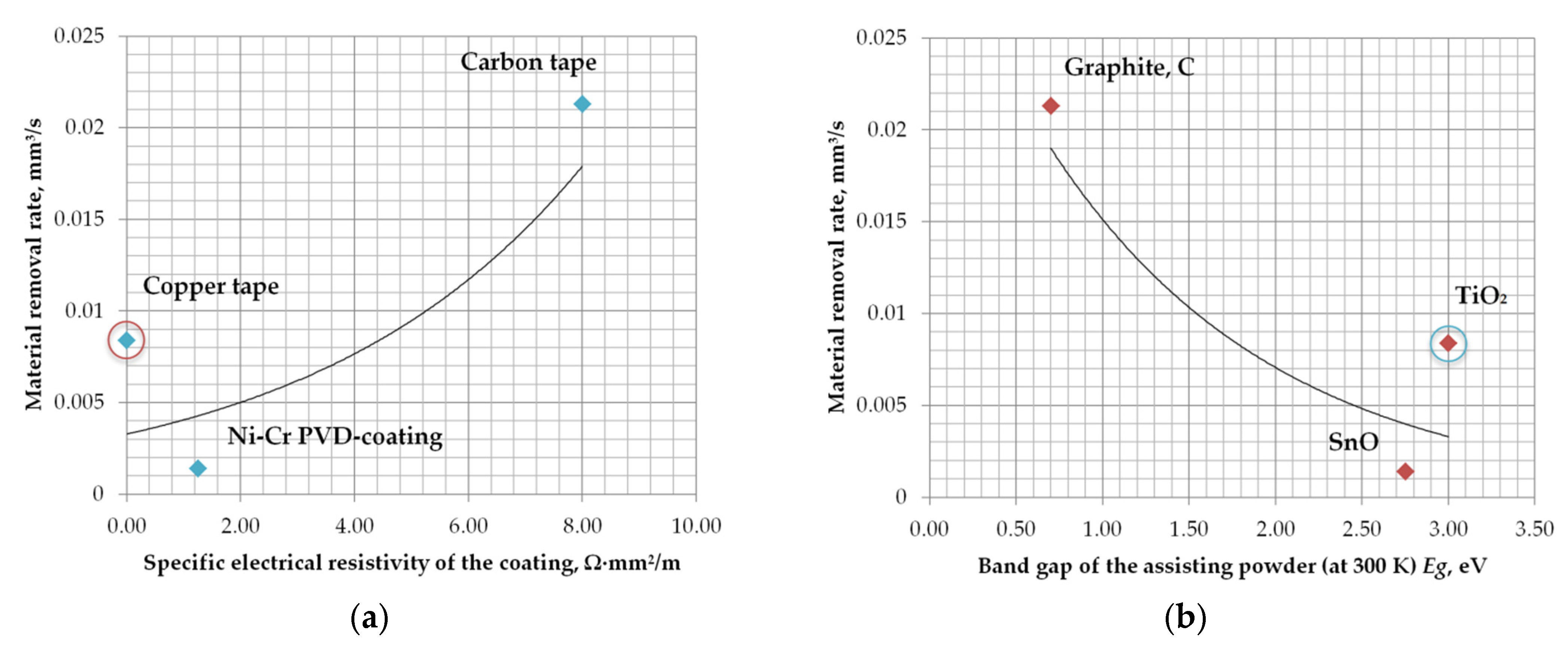
| Primary Electrode Tool | Assisting Electrode Coating | Assisting Suspension | Working Fluid | Material Removal Rate, mm³/s | Reference |
|---|---|---|---|---|---|
| Brass wire, Ø0.25 mm | Copper tape, 40 µm | TiO2 particles, Ø10 µm, 150 g/L | Deionized water | 0.0084 | Current study |
| Brass wire, Ø0.25 mm | Ni-Cr PVD coating, 12 µm | SnO particles, Ø10 µm, 150 g/L | Deionized water | 0.0014 | [80] |
| Copper prism, 5 × 5 mm | Copper foil, 6 µm | - | Mineral oil (hydrocarbons) | 0.0051 | [65] |
| Copper tube, Ø3.5 mm (inner—Ø3.0) | Resin-based carbon tape | Graphite particles, Ø30 µm, 7–10 g/L | Kerosene (hydrocarbons) | 0.0213 | [66] |
Publisher′s Note: MDPI stays neutral with regard to jurisdictional claims in published maps and institutional affiliations. |
© 2022 by the authors. Licensee MDPI, Basel, Switzerland. This article is an open access article distributed under the terms and conditions of the Creative Commons Attribution (CC BY) license (https://creativecommons.org/licenses/by/4.0/).
Share and Cite
Grigoriev, S.N.; Okunkova, A.A.; Volosova, M.A.; Hamdy, K.; Metel, A.S. Electrical Discharge Machining of Al2O3 Using Copper Tape and TiO2 Powder-Mixed Water Medium. Technologies 2022, 10, 116. https://doi.org/10.3390/technologies10060116
Grigoriev SN, Okunkova AA, Volosova MA, Hamdy K, Metel AS. Electrical Discharge Machining of Al2O3 Using Copper Tape and TiO2 Powder-Mixed Water Medium. Technologies. 2022; 10(6):116. https://doi.org/10.3390/technologies10060116
Chicago/Turabian StyleGrigoriev, Sergey N., Anna A. Okunkova, Marina A. Volosova, Khaled Hamdy, and Alexander S. Metel. 2022. "Electrical Discharge Machining of Al2O3 Using Copper Tape and TiO2 Powder-Mixed Water Medium" Technologies 10, no. 6: 116. https://doi.org/10.3390/technologies10060116