1. Introduction
The primary objective of a guidance law for a missile is to intercept a target with the minimum or zero miss distance. Moreover, other objectives, such as impact angle and impact time, also play an important role in realistic engagements based on different missions. In modern warfare, many important targets have been equipped with the advanced missile defense system, like the advanced surface-to-air missile system of surface facilities and the advanced close-in weapon system (CIWS) on warships. These missile defense systems can detect and destroy incoming missiles [
1]. To overcome the threat of such systems, a salvo attack in which a group of missiles can reach the target as simultaneously as possible can be used to improve the survivability of each missile and saturate the defense system of the target. To realize a salvo attack, one approach, called impact time control guidance (ITCG), can be used to regulate the impact time of each missile to a common desired value.
The proportional navigation guidance (PNG) has been widely studied and extensively used due to its easy implementation and effectiveness. Moreover, it has been shown that guidance laws based on PNG can meet the constraint on impact time [
1,
2,
3,
4,
5,
6]. By utilizing linear kinematics and optimal control theory, the authors in [
1] derived a useful impact time control law which combines the well-known PNG and the feedback of the impact time error. The work in [
1] seems to be the first attempt at addressing the impact time control problem. As an extension of the work in [
1], a guidance law was proposed to control both impact angle and impact time in [
2]. Note that the acceleration rate command instead of the acceleration command was used as the control input in [
2] to provide one additional degree of freedom for impact time control. Compared with the result in [
1], a more generalized impact time control guidance based on nonlinear kinematics is derived in [
3] by using the trajectory driven by PNG, with an arbitrary navigation constant as a baseline. In [
4], PNG, with a modified time-varying gain and a bias term, was presented based on the exact solution of the time to go, which was obtained by introducing the Gaussian hypergeometric functions. However, look angle constraints were not mentioned in [
4]. Considering field-of-view (FOV) constraint, an impact time control guidance law was presented in [
5] by combining PNG and an additional biased term of impact time error. Likewise, the research presented in [
6] derived an impact time control guidance law based on the idea of virtual targets by adding two feedback terms about the range error on PNG. A 3D PNG-based impact time control guidance was proposed in [
7] via introducing bias term in both pitch and yaw channels. However, most of the above PNG-based impact time control guidance laws used the linear engagement kinematics or estimated time-to-go, which may generate large errors when heading angle conflicts with small angle assumptions.
Additionally, Lyapunov-based guidance laws were shown effective in controlling the impact time. A nonlinear Lyapunov-based impact time control guidance law was derived in [
8] based on the estimation of time-to-go, as used in [
1,
3]. In [
9], the time-to-go was obtained in terms of the incomplete beta function of the initial heading error, which can be controlled by tuning a single parameter.
In addition, guidance laws based on the sliding mode control (SMC) method were also used to control the impact time. Harl and Balakrishnan developed a guidance law to control impact time and impact angle in [
10] through a line-of-sight rate shaping technique and a second order sliding mode approach. The work in [
10] is one of the earlier studies to solve the guidance terminal constraint problem using SMC. To avoid the singularity problem, a nonsingular sliding mode guidance is proposed in [
11] for the missile to intercept the target at the desired impact time. SMC methods are also employed in [
12,
13,
14,
15,
16,
17] to control the impact time. Many impact time control guidance laws based on SMC methods have complicated structures, making it stressful to deal with the look angle constraint. Moreover, to satisfy impact time constraint, guidance gains or parameters are often tuned by trial and error, or by using an optimization routine, which can make on-line calculations less efficient.
Additionally, the trajectory shaping technique is also worth mentioning in controlling the impact time. The authors in [
18] suggested a guidance law in which the guidance command was expressed as a polynomial function of downrange to go.
The look angle, meaning the angle between the missile velocity and the line of sight (LOS), can determine the axial velocity of the missile, and thus affects the flight time. Thus, regulating impact time by shaping the look angle profiles has attracted a lot of attention. In [
19], the impact-time control problem was solved by imposing a quadratic polynomial shape and a cubic shape on the look-angle profile. The idea from [
19] was also investigated under varying speed cases in [
20].Then, the idea of look angle shaping was further studied in [
21,
22] to meet both the impact time and impact angle constraints. Besides, the range shaping technic was also shown to be effective in controlling impact time. The authors in [
23] derived an impact time control guidance by expressing the range as a quartic polynomial function of time, in which the coefficients of the polynomial were determined by the boundary conditions. Later, the extension of this work was presented in [
24], wherein, the range to target was formulated as a general-order polynomial in time, rather than a quartic polynomial, as used in [
23]. In addition to look angle and range, line-of-sight (LOS) can also be shaped to address the impact time issue. In [
25], a homing guidance law considering impact time and impact angle constraints under limited field-of-view was proposed by employing the line-of-sight shaping approach, where the reference LOS profiles were quartic polynomials in time. Han et.al. proposed a three-dimensional guidance law [
26] for intercepting a maneuvering target with both impact angle and impact time constraints in which the quadratic LOS profiles in the pitch and yaw planes were suggested, respectively. Assuming that the LOS angle could be shaped as a polynomial function of range-to-go, an impact time constrained guidance law using a range-based line-of-sight shaping strategy was proposed in [
27]. Unlike in this paper, in [
25,
26,
27], some parameter values can only be obtained by solving a series of nonlinear equations numerically, instead of determined analytically, which may impose burdens on the on-board computer.
For a class of guidance laws involving the impact time error, it is a challenging issue to precisely obtain an explicit formula of time-to-go. Commonly used methods to estimate time-to-going include using range over speed, using the truncation of an infinite series [
1,
3,
4,
7], or some other methods [
9,
18]. Fortunately, a closed-form solution of the impact time in deviated pure pursuit (DPP) can be obtained explicitly [
28]. In [
29], an impact time control guidance law based on DPP was proposed by shaping the dynamics of the exact impact time error. In [
30], an optimal control-based guidance law was developed by establishing the relationships between the impact time, the desired look angle, and the nominal commanded acceleration, based on DPP. Considering the control loop dynamics, a decoupled approach where the desired lateral acceleration was derived using DPP was proposed in [
31] to intercept a moving, but non-maneuvering, target at a pre-specified time. However, for stationary targets, the lateral acceleration command given by DPP becomes unbounded at interception.
In addition to DPP, the circular guidance (CG) can also provide an analytical solution of the impact time according to basic geometric rules. Conversely, in scenarios where the missile moves with a constant speed, if the desired time-to-go and current range to target are known, the corresponding desired look angle can be determined uniquely. In [
32], by tracking the desired look angle, which was approximately obtained by solving a transcendental equation with Taylor series expansion, the trajectory could converge to a circular arc in a finite time. However, constraints on look angle were not considered in [
32]. While in [
33], Tsalik and Shima proposed two approaches to obtain the approximate desired look angle, one using the MATLAB curve-fitting tool, and the other iteratively using the Newton–Raphson method. Then, a PI-controller was used to eliminate look angle errors. As can be seen, both [
32,
33] involved numerical algorithms in calculating desired look angles.
Other than the ITCG methods mentioned above, the second approach to realize the simultaneous arrival is cooperative guidance, in which the communication network is often employed to improve the collaborative capacity between missiles [
34,
35,
36,
37]. The cooperative guidance method is not considered here.
In this paper, inspired by [
29,
33], CG is chosen as the baseline of the proposed guidance law, called fixed-time circular impact time guidance (FCITG). Unlike the work in [
32,
33], the proposed FCITG can meet the impact time constraint through shaping the dynamics of the impact time error, straightly detouring the estimation of the desired look angle or the time-to-go. Besides, the proposed FCITG has a wide range of the desired impact time when the limitation of the look angle is not considered. Further, the look angle constraint imposed by the seeker can be readily taken into account by introducing DPP, when necessary. Actually, if the seek can handle look angles greater than or equal to 90° during DPP phase, the upper limit on the desired impact time still does not exist.
For a salvo attack, to guarantee that different missiles launched from different platforms or different locations can hit the target simultaneously, the fixed-time stability is employed in designing the FCITG. Note that the fixed-time stability is different from the finite-time stability. Specifically, the settling time of fixed-time stability is globally bounded, even when the initial error tends to infinity, whereas the settling time of finite-time stability grows unboundedly when the initial error approaches infinity [
38]. Motivated by [
39], a fixed-time controller is developed to achieve zero miss distance at the desired impact time. More importantly, criteria for tuning the parameters in FCITG are also established in an explicit form, which can be utilized efficiently.
Compared to the existing ITCG laws in the literature, the main contributions of this paper can be encapsulated in the following key points.
(1) Compared to [
1,
6], the proposed FCITG is derived in nonlinear frameworks, which aids in preventing errors that arise due to linearization. Besides, the absence of small angle approximation enables FCITG to deal with large look angles.
(2) In comparison with [
14,
32,
33], the proposed FCITG does not involve tracking desired look angles. Thus, numerical calculations of the desired look angle from the desired time-to-go can be circumvented, which improves the efficiency of the on-board computer.
(3) Unlike the finite-time stability used in [
14,
29], the fixed-time stability is employed in designing FCITG. Therefore, the impact time errors will converge to zero within a predefined fixed time, despite of initial conditions. This feature will stand out in a salvo attack, where each missile may have different initial states.
(4) Different from [
15,
33], the parameter values can be determined from the analytical criterion instead of by trial and error or on-line calculation at each time instant. Moreover, a certain combination of the values of the two parameters is applicable for many different desired impact times.
(5) Finally, the guidance proposed is of a simple form, thus leading to an easy implementation.
The rest of this paper is organized as follows. A preliminary summary of fixed-time stability is introduced in
Section 2. In
Section 3, a problem statement and the guidance law design are offered. In
Section 4, the criteria for the selection of parameter values are established. The extension of FCITG to moving targets and the salvo attack scenario are investigated in
Section 5. Simulations are carried out in
Section 6 to validate the effectiveness of the proposed guidance law.
Section 7 concludes this article.
Note that throughout this paper, for and , the function is defined as , where is the sign function.
3. Problem Statement and Guidance Law Design
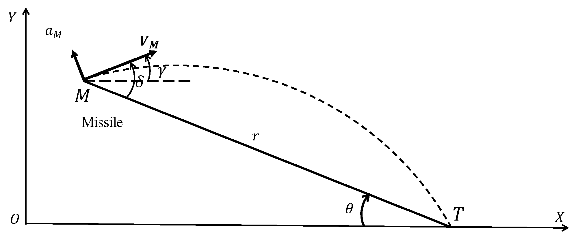
In
Figure 1, the planar engagement geometry between the missile and the target is shown. The X-O-Y is the inertial Cartesian reference frame. The missile
has a constant speed
, and the target
is stationary. Note that
is the instantaneous range between the missile and the target,
is the flight path angle of the missile, and
is the line-of-sight angle. Moreover,
is the look angle, which is the angle between the missile velocity and the line of sight. The acceleration perpendicular to the velocity vector is represented by
.
The nonlinear kinematic engagement equations are given by
Taking the derivative of (5) yields
The desired impact time is represented by
. Then the desired time-to-go is defined as
where
denotes the time elapsed from the beginning of the guidance.
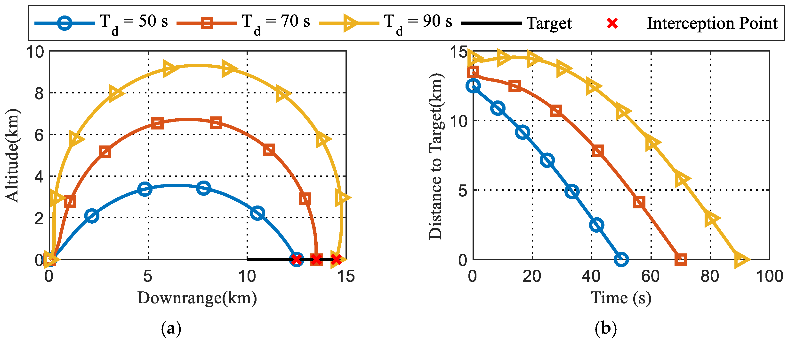
The purpose of FCITG is to hit the target at
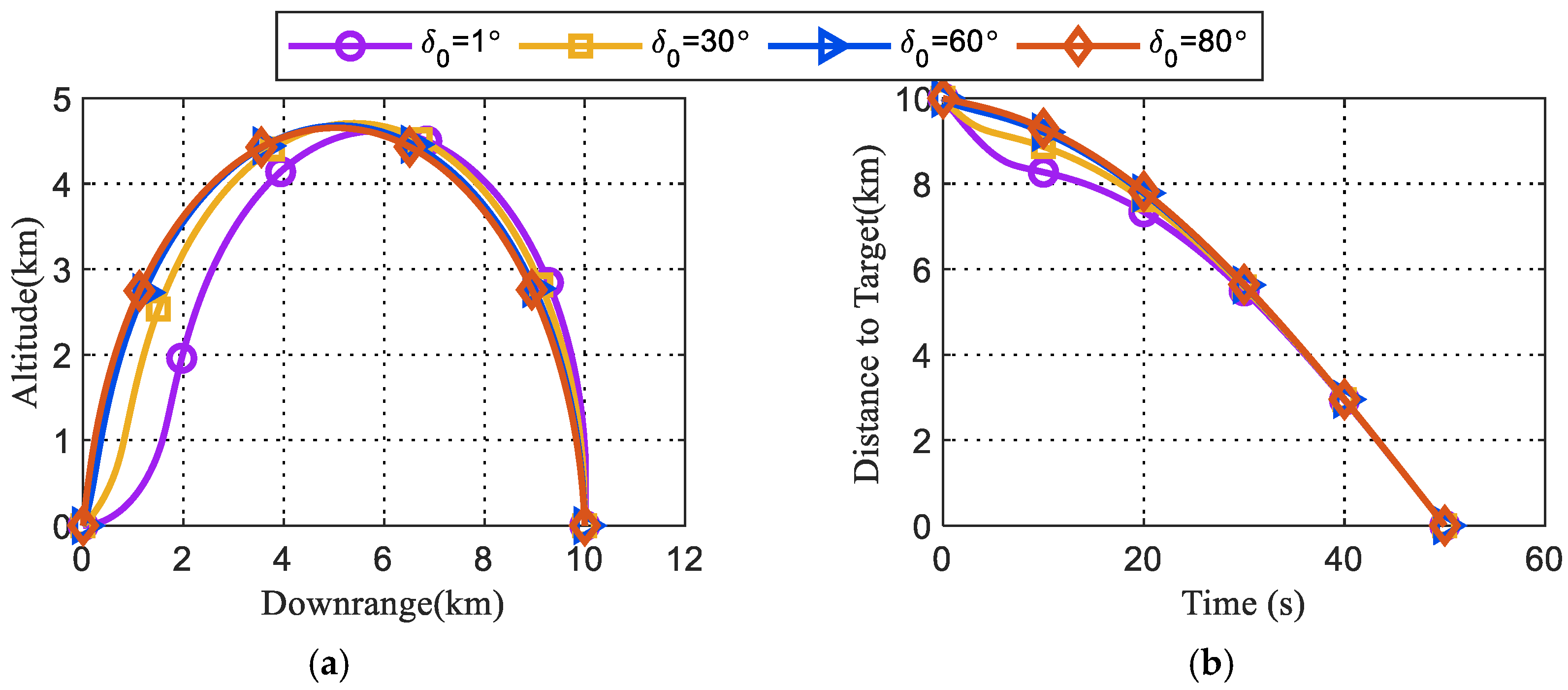
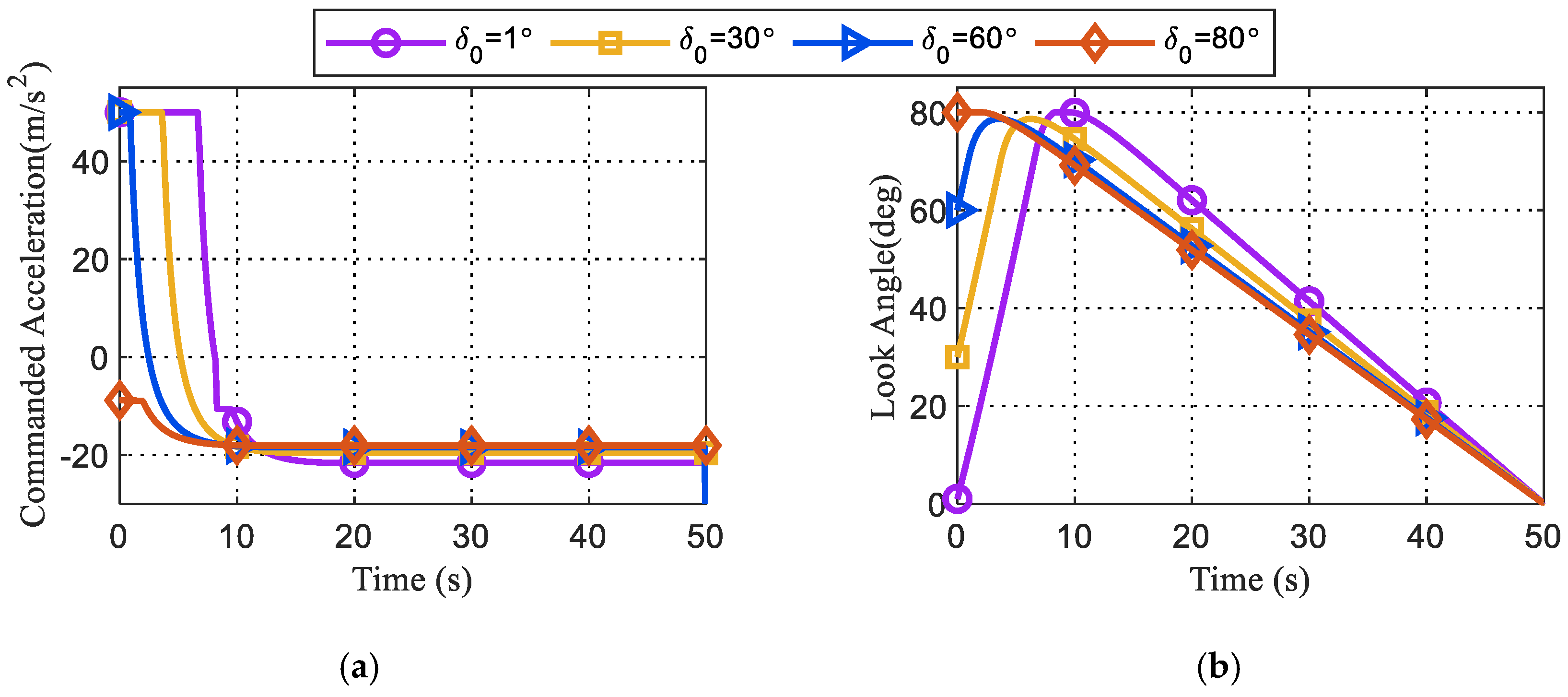
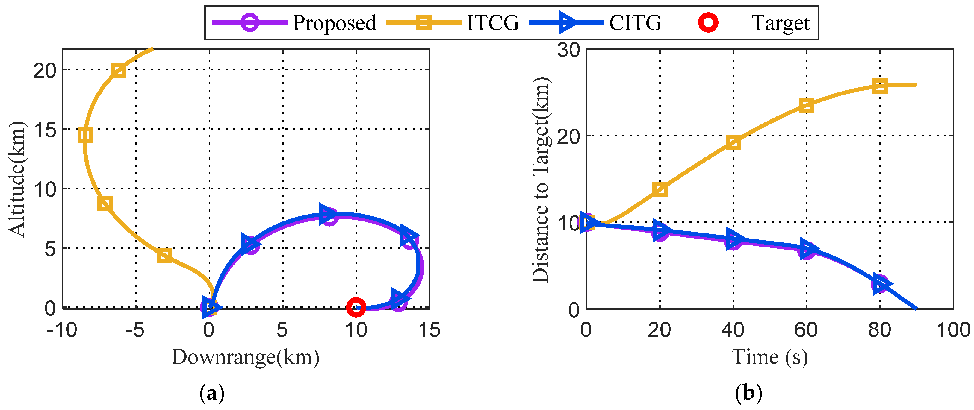
. If the missile keeps moving with a constant speed along a circular arc connecting its current position and the target, the total flight time can be obtained accurately and readily controlled to satisfy the impact-time requirement. In [
32,
33], based on the desired time-to-go, an approximation to the desired look angle can be calculated by solving a nonlinear equation. Afterwards, the look angle is regulated to converge to the desired values to eliminate impact time errors. Nevertheless, the longer the time-to-go, the greater the difference between the exact desired look angle and its approximate value. To overcome this drawback, time-to-go, rather than the look angle. is considered. For a missile guided by CG, the impact time can be obtained from geometric rules as
where
and
represent the initial range to target and the initial look angle, respectively.
By converting the initial values in (8) into current ones, the time-to-go under the circular guidance can be obtained as
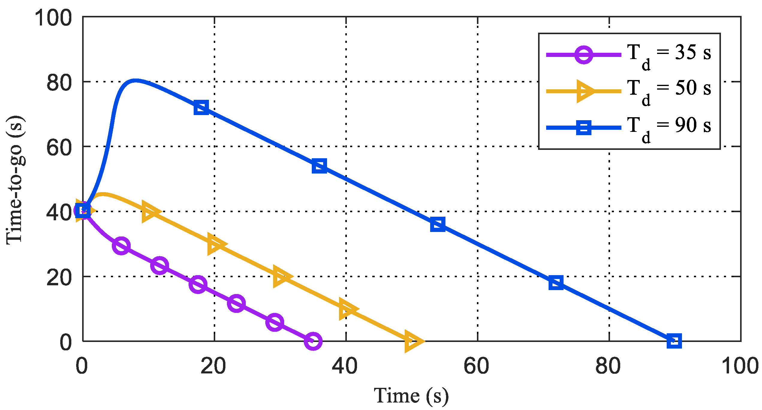
Herein, is derived without making any small angle assumptions. Note that the nonlinear framework circumvents the limitations due to linearization, especially for large initial heading errors. In (9), as 180°, , meaning that the upper limit of the intercept time is unbounded; and as 0°, , meaning that the lower limit of time-to-go is . Thus, the feasible desired impact time is , where corresponds to the impact time when the missile is on the direct collision course with the target. It is worth noting that the aforementioned is not only the lower limit of the impact time of the proposed FCITG, but also of any other guidance laws.
The impact time error is defined as
The main idea of FCITG is to shape the dynamics of
so that
is infinitely close to or equal to
before interception occurs. On differentiating
in (9), with respect to time, we have
From (7), the time derivative of
is
By combining (10)–(12) the time derivative of
can be obtained as
On substituting (2), (4), and (5) into (13), the dynamics of the interception time error can be derived as
Based on the present analysis, a main proposition is given below.
Proposition 1. For a planar missile-target engagement, if lateral acceleration of the missile is chosen aswhere
,
and
are two positive constants to be tuned, then
is guaranteed to converge to zero within a fixed time, only depending on
and
for any arbitrary initial condition. As a result, after the impact time error becomes zero, the missile will move along a circular arc and hit the target at the desired impact time, with zero miss distance. Proof. Taking the following Lyapunov function candidate into account,
The time derivative of
can be obtained as
where
is defined as
.
Substituting (17) into (16) yields
On substituting (20) into (19), one can get
On expanding (21) and rearranging,
can be expressed as
Note that when error
approaches to zero, system (20) can be approximated by the 0-limit subsystem [
39]
Then, to verify the asymptotic of system (23), a Lyapunov function is selected as
The time derivative of
can be calculated as
While, when impact time error
approaches to infinity, system (20) can be reduced to the
-limit subsystem [
39]
Like the analysis in (23), a Lyapunov function candidate of system (26) and its derivative can be obtained as
Since Lyapunov function candidates are positive and their corresponding derivatives are semi-negative, systems (20), (23), and (26) are all asymptotically stable. According to Lemma 1 in [
39], it can be concluded that the original system (20) is fixed-time convergent. As a result, the impact time error can converge to zero within a fixed time, independent of initial conditions. Finally, the missile will move along a circular arc toward the target.
This completes the proof. □
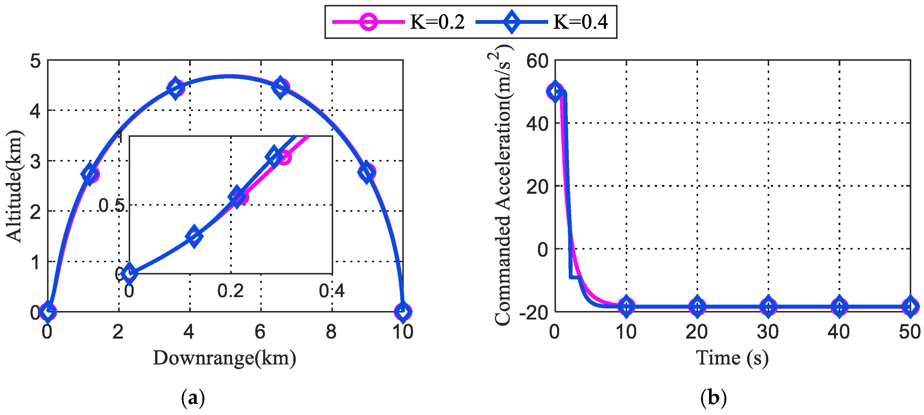
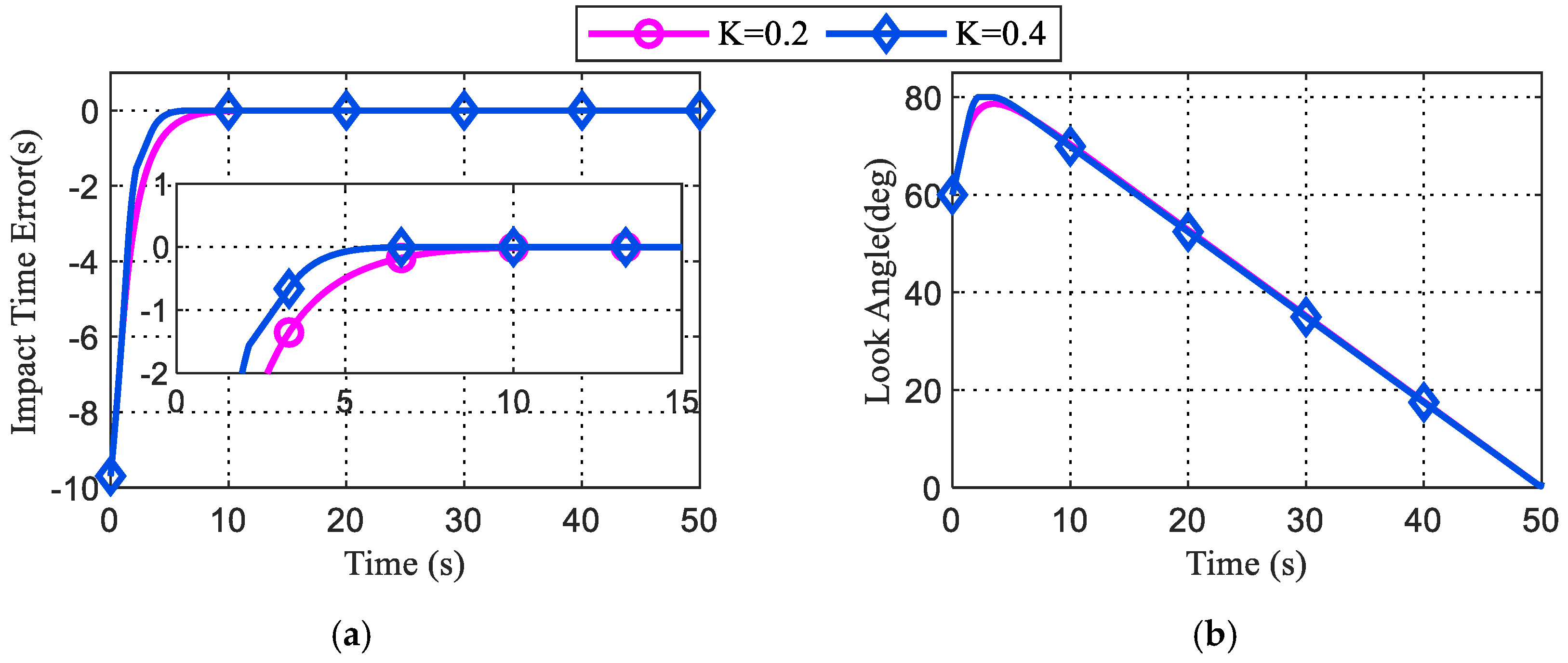
Remark 1. Given that
, it can be derived that
and
. Hence, a noticeable feature of system (20) is that it contains one term with a fractional exponent smaller than 1, and another one term with a degree more than 1. When
, the component using the degree larger than 1 can enable a more rapid rate of convergence. Likewise, when
, the term with the fractional exponent smaller than 1 predominates other terms to provide faster convergence. In summary, using different powers can ensure a faster convergence in any case.
Upon substituting
and
from (15) into (17), the lateral command acceleration can be obtained as
The first term of (28) is the circular guidance command required by the missile to stay on a circular course. The second term is to eliminate the impact time error. If the initial impact time produced by CG is not equal to the desired impact time, this correction term could bring the missile onto a circular course to achieve the guidance objectives. Assuming = 0 in (28), the guidance command becomes that of circular guidance, which will be shown in the following proposition.
Proposition 2. With the guidance command given by (28), once
becomes zero at
, the radius of the missile’s trajectory remains constant, and retains its value at
till the end of the engagement.
Proof. At any moment, the radius of curvature of the missile trajectory can be obtained as
Substituting (28) into (29) yields
At
, the impact time error
becomes 0 as well as
. Hence,
can be written as
The time derivative of
can be obtained as
On substituting (28) with
= 0 into (32), one can obtain
which means that the missile will fly along a circular arc, with a constant radius, to the target from the time
on.
This completes the proof. □
To deal with look angle constraint problems, the variation of look angles will be studied. On substituting (28) into (6),
can be obtained as
Proposition 3. The impact time error and Ξ always have the same sign, meaning they always remain identical in positivity, negativity, or nullity.
Proof. If
,
can be deduced from the definition of
in Proposition 1. If
,
composes of three positive terms. Consequently,
for
, then
This completes the proof. □
Remark 2. According to the proof of Proposition 1, before
becomes zero. If
, then
as well as
by Proposition 3. Consequently,
holds throughout the engagement from (34). Therefore, the look angle will decrease monotonically to zero in case of
. Further, taking the partial derivative of (9) with respect to
yields It can be observed from (35) that
holds for
. Thus, when
, the look angle is expected to be smaller to reduce the impact time error.
Remark 3. Here, one of the rules for tuning K is proposed. If
, a larger look angle is required for
to track
from (35), which means that
ought to be positive in the initial phase. Known from the proof of Proposition 3,
produces
. Hence, the inequalityholds at the beginning. If
is chosen asthenis ensured. Accordingly,
can be achieved due to (34). Thus,
will increase at the beginning of the engagement. Now, the behavior of
for
with
chosen as (36) is investigated. For the sake of convenience, we define
assuming that
keeps increasing before
vanishes. As a result, the value of
will always turn out to be positive because
will approach zero according to Proposition 1, and the value of
will decrease due to the growing value of
under the above assumption. Consequently,
will decrease due to (34), which contradicts the above assumption. In summary, if
and
was chosen as stated in (36),
will rise and then fall rather than keep rising.
Further, to study the singularity of the guidance command later, a proposition about the emergence of a zero look angle is suggested.
Proposition 4. Given that
,
, occurs only at the end of the engagement.
Proof. It can be stated from Proposition 1 that for , which shows that the magnitude of keeps decreasing with time till zero.
If
, then
, which means that
holds before the impact time error becomes zero at
. If
, such that
, then
So far, there is a conflict between (39) and (40). So, in cases where , = 0 only appears at the end of the circular trajectory at time .
If
, then
. As seen in Remark 3,
will first increase and then decrease when
is selected properly. In the phase where
increases,
evidently cannot be zero. While, in a phase where
decreases, once
converges to zero at
, the trajectory will change to a circular arc, where the look angle will decrease to zero with a constant rate, which had been proved in [
28]. That is,
is not zero at
. Hence, there does not exist
, such that
= 0. Finally,
can only be zero at the end of the engagement in cases where
.
This completes the proof. □
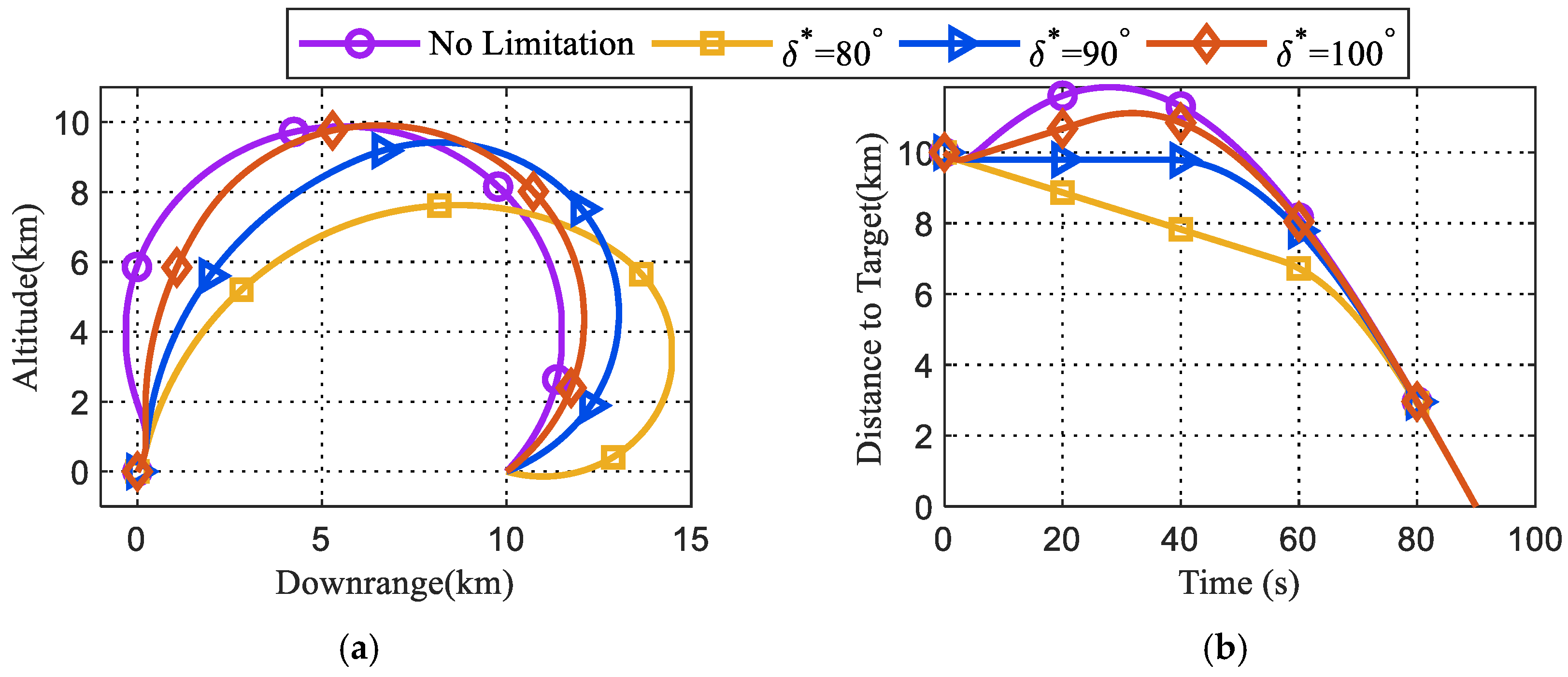
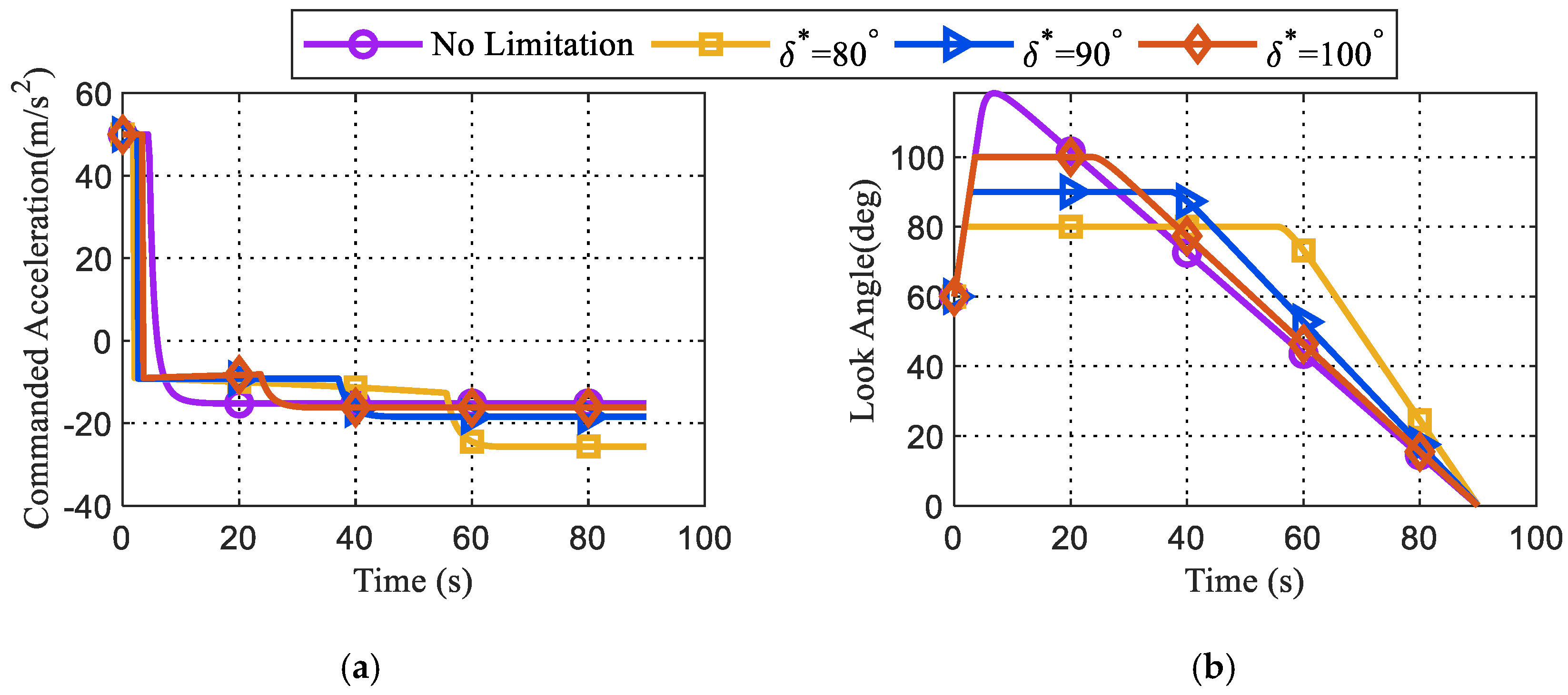
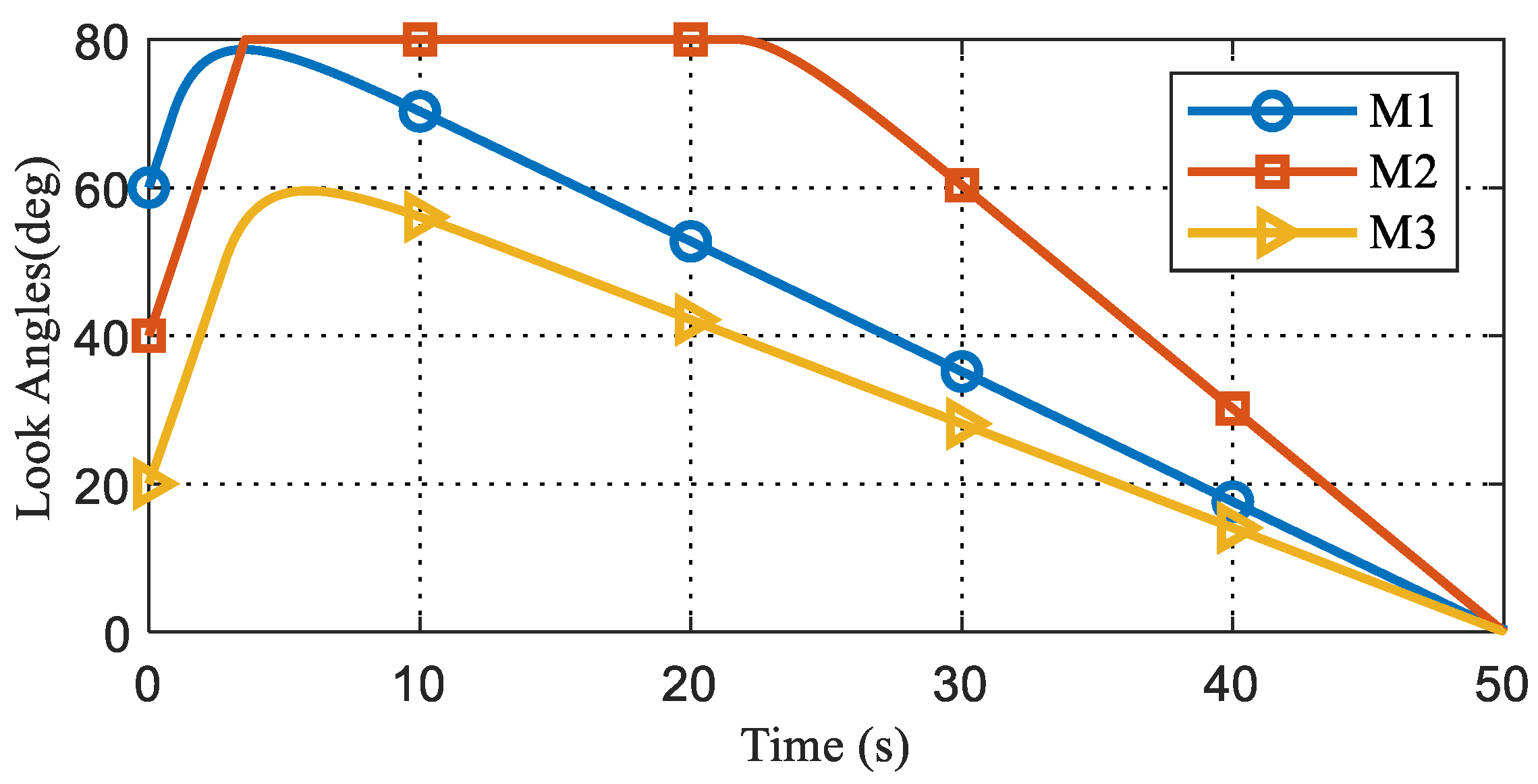
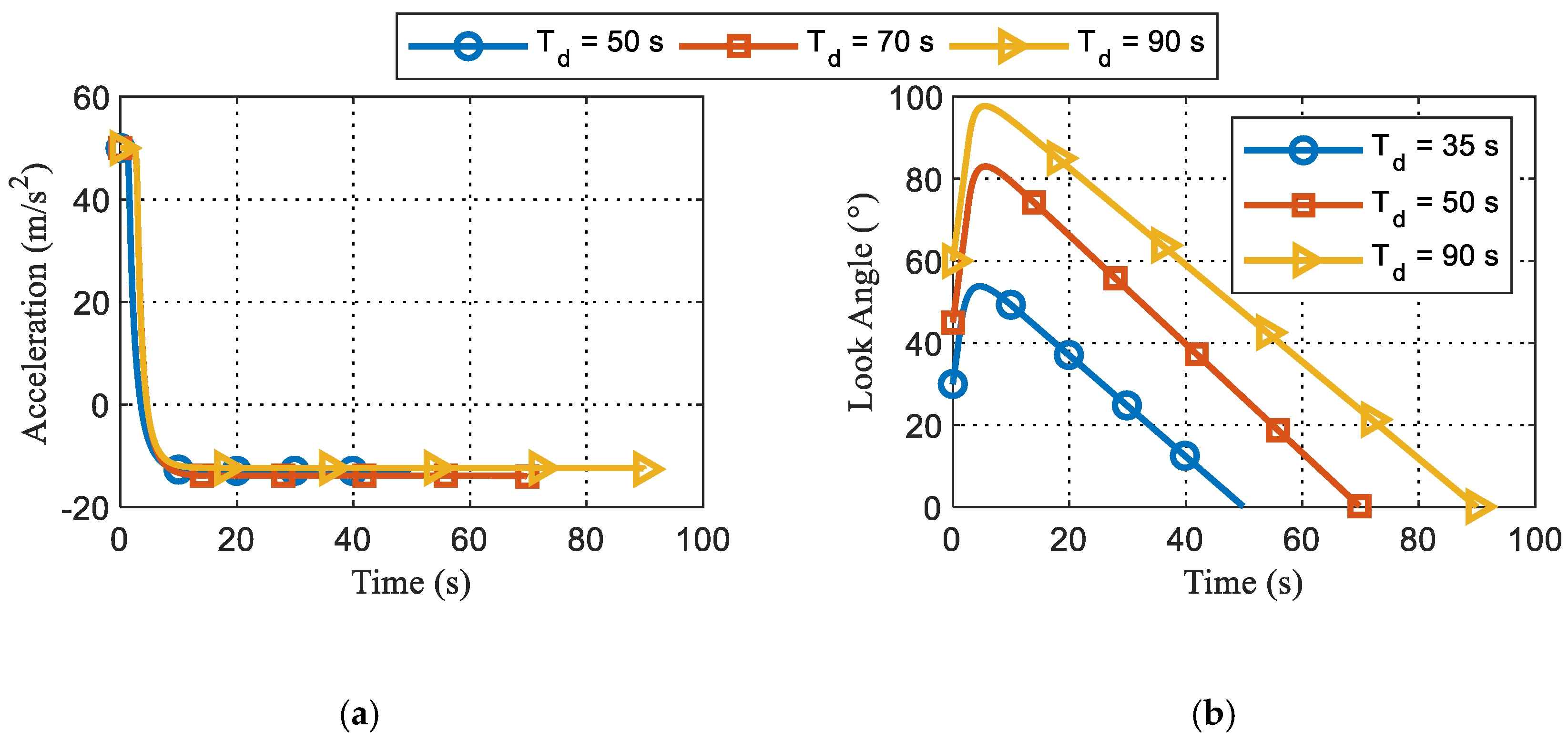
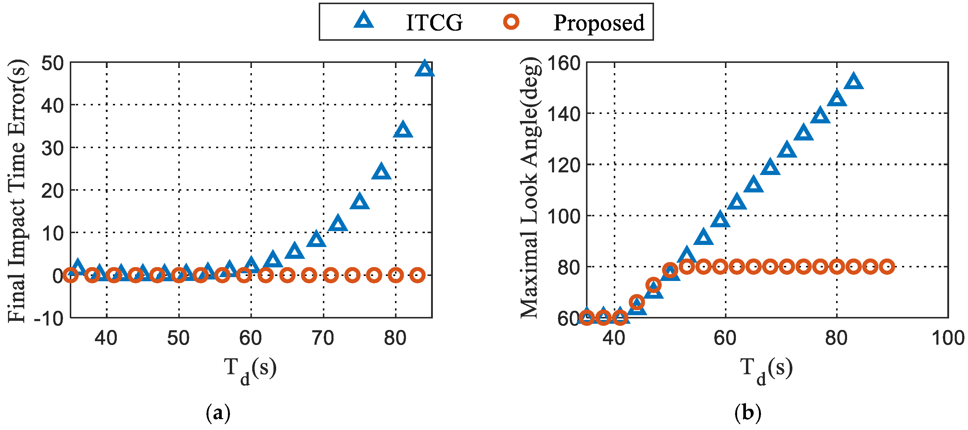
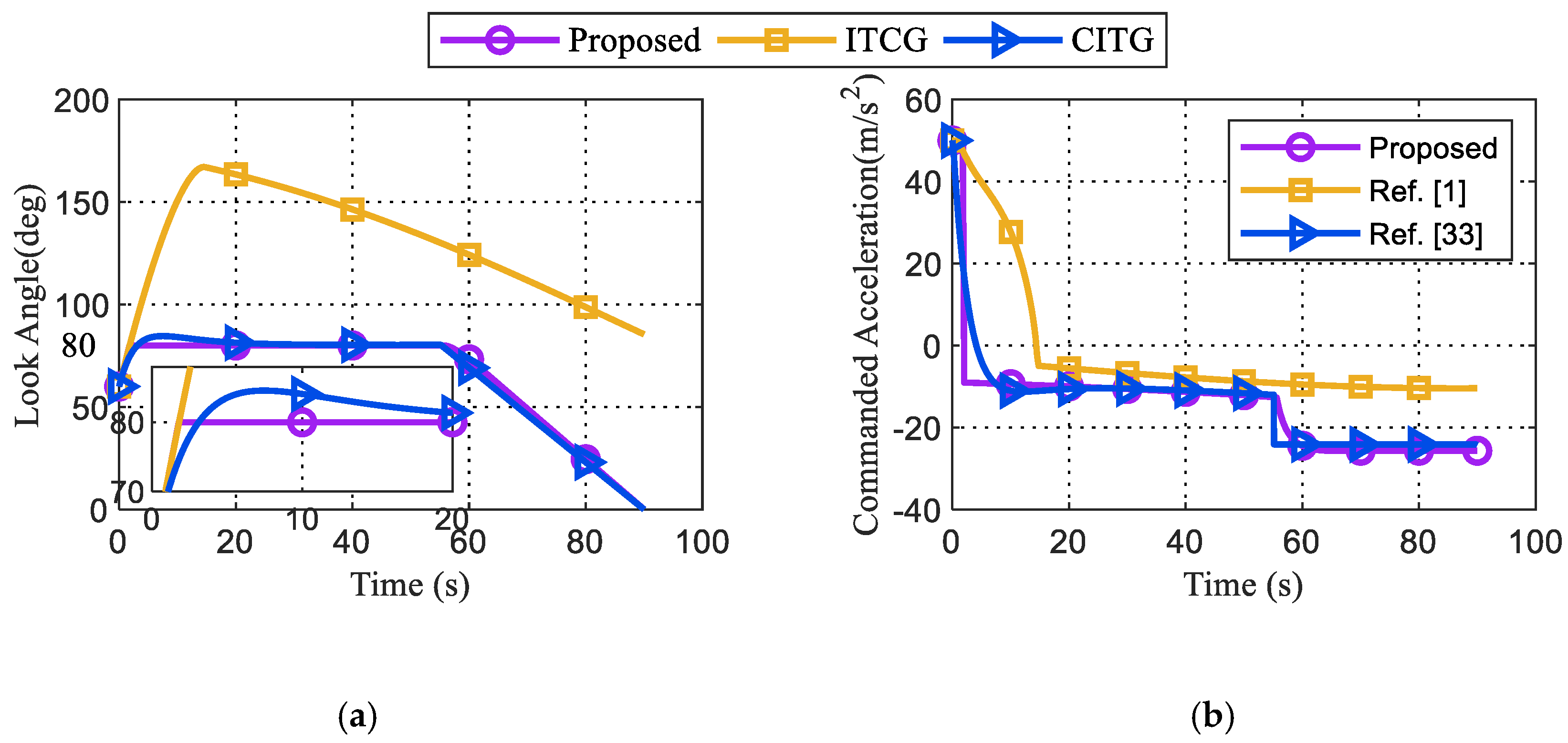
To address the look angle constraints, we define as the allowed maximal look angle, such as 80°, 90° and 100°, which is limited by the seeker. If the desired impact time is less than the initial expected impact time by circular guidance, the look angle is monotonically decreasing, according to Remark 2. If is provided, will not challenge the look angle constraints.
If the desired impact time is greater than the initial expected impact time by circular guidance, the look angle will first increase according to Remark 3, and then the maximum look angle represented by
occurs when
0 or
. If
, the proposed FCITG can be used throughout the engagement. However, if
, to avoid violating the look angle constraint, as soon as
reaches
at time denoted by
, a deviated pure pursuit (DPP) will be applied to keep the look angle constant. On substituting instantaneous states of the missile generated by DPP into equations under FCITG, the virtual impact time error can be expressed as
where
and
represent the time and the instantaneous range when DPP comes to be applied, respectively.
If the missile keeps flying under DPP from
before reaching the target, the impact time can be calculated as
However, in most cases, is not equal to . Thus, it is important to determine the switching time from DPP to FCITG. Then, a useful proposition is put forward.
Proposition 5. , such that .
Proof. At ,
can be guaranteed because the look angle is increasing at that moment or has reached the relative maximal value. If at , the proposition apparently stands. Now, the case at is mainly investigated.
On substituting (42) into (41) and rearranging, the final virtual impact time error can be obtained as
In a real engagement, to meet the impact time constraint,
should hold, independent of the guidance law. The longer the desired impact time, the greater
should be. If
is large enough, the second term of (43) could be positively significantly large. Thus,
from (38). To be more specific, when
, we can obtain from the proof of Proposition 1 that
and in stage from
to
where the look angle increases, one can get
where
is the settling time of the impact time error, which will be solved in
Section 4.
If
holds, then combining (43)–(46) yields
Note that (46) is a sufficient condition for (47). During PPD, and are both continuous functions of time. Therefore, , such that 0.
This completes the proof. □
Once
becomes positive at
,
will be negative; as seen from (34), the proposed FCITG will be employed again till interception. Based on the preceding analysis, when the look angle constraint is considered, the guidance command by FCITG can be modified as
Then, the singularity of the guidance command will be discussed.
Proposition 6. Given that
is not equal to 0, the proposed FCITG does not suffer from singularity problems.
Proof. From Proposition 4, if , zero look angle only occurs at the interception moment meaning that cannot be zero before converges to zero. Thus, the value of
in (48) is always bounded before vanishes, ensuring the boundedness of the guidance command. After vanishes, the guidance command given by (28) or (48) degenerates to that of circular guidance, in which the guidance command stays constant.
This completes the proof. □
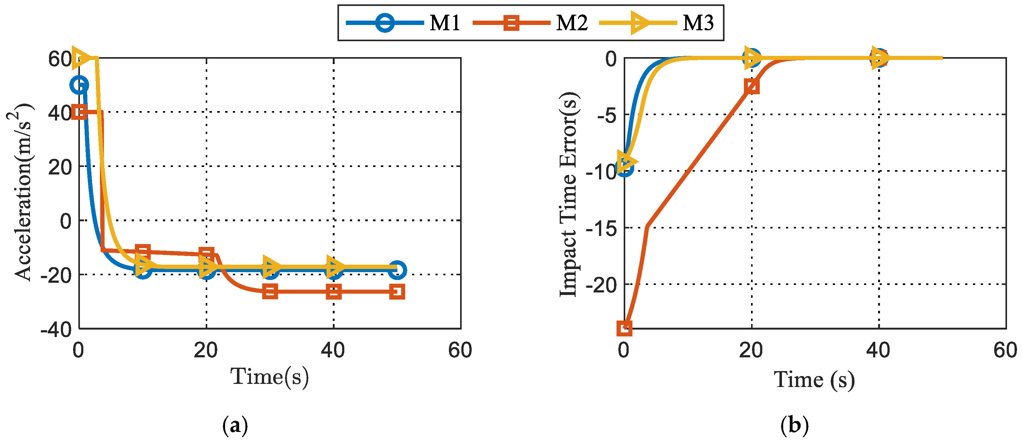
Note that even if
occurs, the lateral acceleration can deviate the look angle from zero before FCITG is applied. However, when
is close to zero and
, the guidance command given by (48) will grow considerably large. For example, the value of
will blow up to about 300 when
rad. To address the singularity problem, we can saturate the magnitude of the guidance command to its maximal value denoted by
. In practice, the guidance command in (48) can be reformulated as


