1. Introduction
With the rapid development of science and technology and high–precision industries in the world, precision instruments have attracted more attention. The development of products and equipment with high precision, high density, and high reliability is a major trend in the current era. The problematic term closely related to precision instrumentation is “vibration”. Negative vibration will affect the function of precision instruments, aggravate the fatigue and wear of equipment, and seriously restrict the development of the high–precision industry [
1,
2,
3]. Since the beginning of the 21st century, with the rapid development of space technology around the world, all kinds of spacecraft carrying a large number of high–precision and precise equipment are continuously entering space, and the requirements for a spacecraft attitude adjustment, communication transmission, and stable operation are gradually changing [
4,
5]. In addition, spacecraft platforms are developing rapidly in the direction of integration, large scale, and flexibility. This will aggravate the instability of spacecraft, cause more serious disturbances, and may have a significant impact on the stable operation of spacecraft [
6]. Therefore, how to suppress negative vibration and maintain the good performance of spacecraft in orbit is still a hot and difficult research issue [
7].
For a spacecraft in orbit, vibration will be generated due to the environmental impact and mechanical operation of the spacecraft itself. Take an orbiting satellite, for example, the momentum wheel [
8,
9,
10], solar sail [
11,
12], refrigerator [
13,
14], and sweeping mechanism [
15,
16] on the fuselage will vibrate during operation. These vibrations are characterized by small amplitude, wide frequency band, sensitivity, inherent existence and difficulty in measurement [
17]. Scholars have divided the vibration characteristics of spacecraft into three categories: quasi–static micro–vibration (less than 0.001 Hz), low–frequency micro–vibration (0.001–10 Hz), and medium– and high–frequency micro–vibration (higher than 10 Hz). The specific introduction is in chapter 2.1. Because damping in the spacecraft’s working environment is very small, micro–vibrations can last for a long time, which will worsen the working environment of onboard instruments [
13] and even lead to the failure of space missions [
18,
19]. Therefore, in order to ensure the normal operation of spacecraft with high–precision and precision equipment, it is necessary to control the micro vibrations.
In engineering technology, vibration isolation technology is the most effective means to suppress vibration [
20]. According to the characteristics of low–frequency vibration of on–orbit spacecraft, some quasi–zero–stiffness isolators can be used [
21]. However, this control method is in the category of passive vibration isolation and cannot meet the requirements of active vibration suppression. Therefore, many researchers have proposed semi–active, active, and integrated active/passive vibration isolation technology [
22]. The most typical and widely used active technology, with a great vibration isolation effect, is the Stewart vibration isolation platform with a six–degree–of–freedom (6–DOF) parallel mechanism. Based on the Stewart six–degree–of–freedom parallel platform and combining the advantages of an intelligent structure, it has the characteristics of compact structure, strong fault tolerance, large bearing capacity, high pointing accuracy, and stable dynamics [
23]. It can be used as a connecting device between high–precision space–borne equipment and the spacecraft body to suppress micro–vibrations [
13]. At the same time, it is also widely used in motion simulation [
24,
25,
26,
27], industrial manufacturing [
23,
28], mechanical docking [
25,
29,
30], micro–vibration control [
31,
32,
33], and medical assistance [
34,
35,
36].
Based on current research, there has been no significant qualitative change in the Stewart platform community. However, with the development of 4D printing technology and the use of a low–melting–point alloy as a variable stiffness material, novel development ideas are being put forward for structural modification of the Stewart damping platform. It is thus necessary to summarize the development process and research status of the Stewart platform. First, the source of micro–vibrations and the advantages and disadvantages of four vibration isolation technologies are briefly discussed. Second, according to the characteristics of high motion accuracy and large stiffness mass ratio, the development process of the Stewart vibration isolation platform in the field of aerospace micro–vibration control is summarized. Then, the theoretical research results of the platform in the field of micro–vibration and the research status of the rigid/flexible platform in the field of aerospace micro–vibrations are sorted out. Finally, the development of the novel integrated omnidirectional, full–frequency, multi–functional Stewart platform with variable stiffness and active control is proposed using electro thermal intelligent materials and low–melting–point alloys as substrates and 4D printing technology in order to meet the vibration isolation/damping requirements of the current spacecraft toward the development of miniaturization and integration.
2. Classification and Suppression of Micro–Vibrations
2.1. Classification of Micro–Vibrations
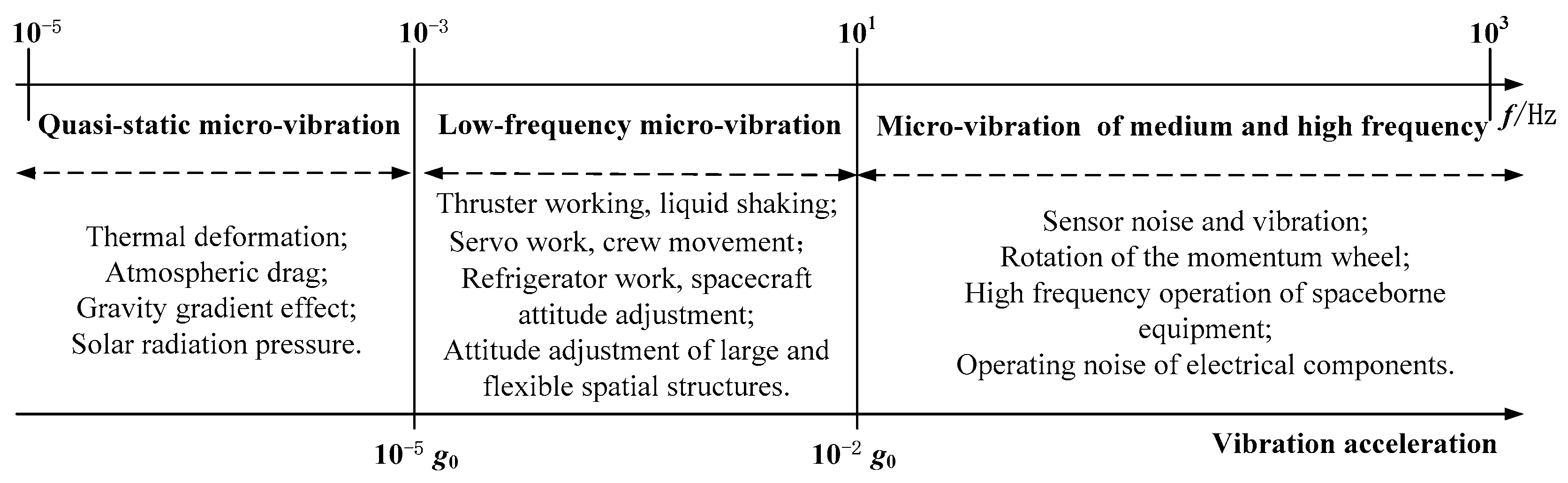
Micro–vibration usually refers to mechanical vibration or disturbance occurring at a frequency between 0.01 Hz and 1 kHz [
37]. Scholars have conducted a great deal of research on the dynamic micro–vibration environment of spacecraft and have divided the interference source into three frequency bands [
38], as shown in
Figure 1.
The three frequency bands are as follows: quasi–static micro–vibration (less than 0.001 Hz), low–frequency micro–vibration (0.001–10 Hz), and medium– and high–frequency micro–vibration (higher than 10 Hz). Among them, quasi–static micro–vibration is mainly induced by thermal deformation, atmospheric resistance, gravity gradient effect, and solar radiation pressure, and the vibration acceleration is
(
= 9.8 m/s
2, and the same below). Low–frequency micro–vibration is mainly induced by the low–frequency operation of space–borne equipment, such as thruster operation, liquid shaking, refrigerator operation, and attitude adjustment movement of the solar panels [
39]. The vibration of low–frequency micro–vibration is random and complex, and the vibration acceleration is
. The frequency of medium– and high–frequency micro–vibration is high, the amplitude is small, and the acceleration is greater than
and is mainly caused by the high–frequency operation of space–borne equipment such as sensors and momentum wheels [
40,
41,
42].
These micro–vibrations have small amplitude and a wide frequency band and are difficult to measure, diverse, and inherent, which makes the space mechanics environment extremely complex [
43]. They will not only stimulate vibration of the overall structure of the spacecraft but also cause attitude instability. Therefore, how to control micro–vibration in spacecraft is a very challenging topic.
2.2. Suppression of Micro–Vibration
Micro–vibration suppression technology mainly refers to vibration isolation, which mainly uses corresponding active or passive components to reduce the interference energy in the vibration propagation. According to different suppression principles, vibration isolation technology can be divided into passive, semi–active, active, and integrated active–passive vibration isolation technology [
13]. These four vibration isolation technologies are briefly described below in terms of the principles, characteristics, structural design characteristics, and advantages and disadvantages of the vibration isolation effect.
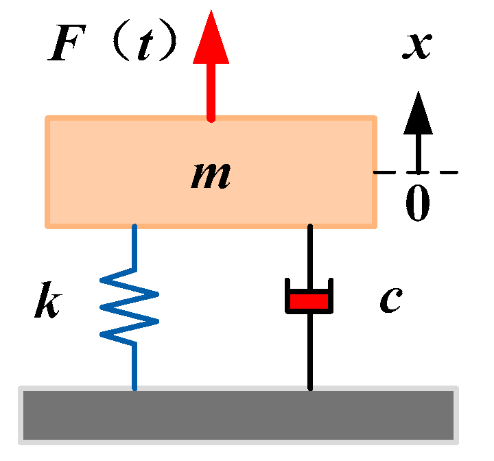
2.2.1. Passive Vibration Isolation Technology
Passive vibration isolation technology reduces the vibration intensity in the vibration propagation path by using passive elements [
6]. The most important feature of passive vibration isolation technology is that it does not need external energy to obtain good vibration isolation by changing the stiffness and damping coefficient of some structures. To demonstrate the mechanisms, the working principle of a typical passive vibration isolation system is shown in
Figure 2.
2.2.2. Semi–Active Vibration Isolation Technology
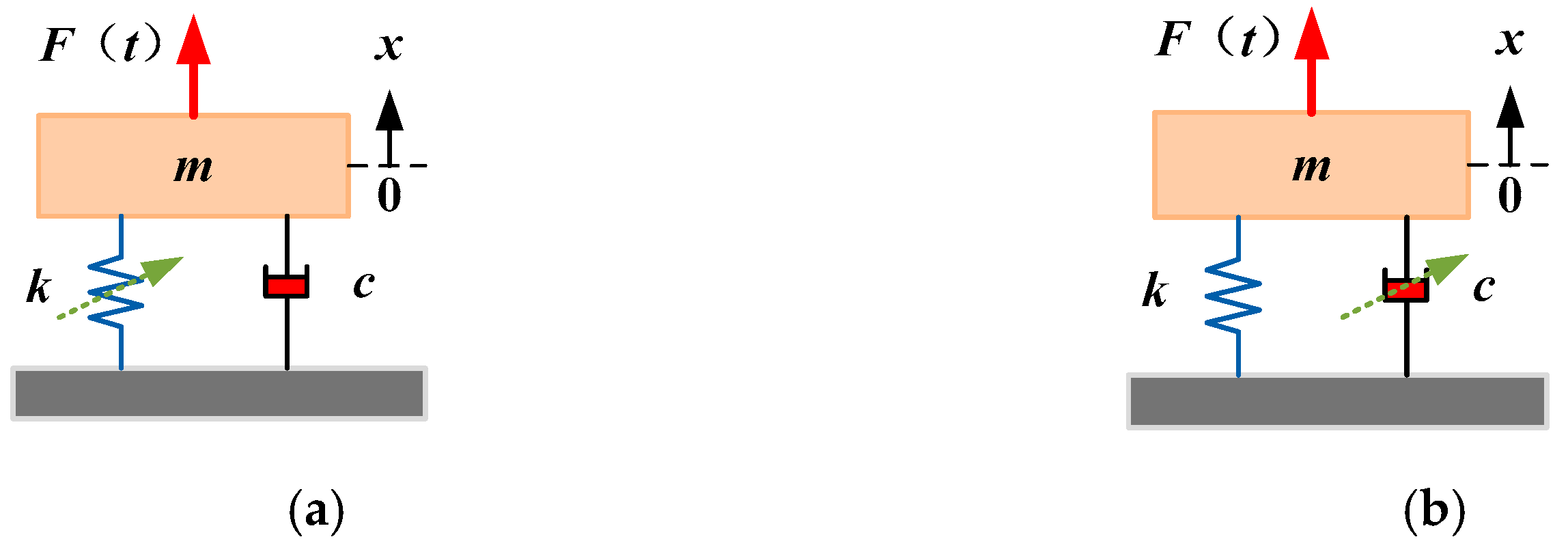
To obtain ideal vibration isolation efficiency, semi–active vibration isolation technology can change the stiffness or damping of the whole system according to different vibration environments [
44]. Different from active vibration isolation technology, semi–active technology needs a small amount of external energy to change the damping or stiffness. To demonstrate the mechanisms, the working principle of a typical semi–active vibration isolation system is shown in
Figure 3. Semi–active vibration isolation technology has the advantages of active adjustment, small–scale suppression of micro–vibration, less energy consumption, and high stability, among others. However, this technology cannot completely isolate low–frequency vibration interference [
13], and there is still a large resonance peak at a certain natural frequency. Therefore, semi–active vibration isolation technology is rarely used for micro–vibration suppression in a spacecraft.
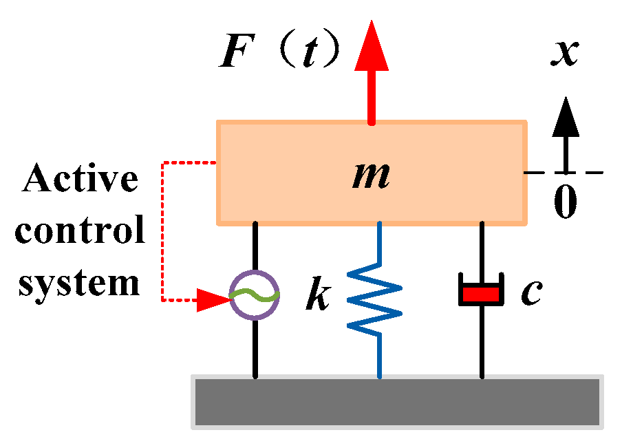
2.2.3. Active Vibration Isolation Technology
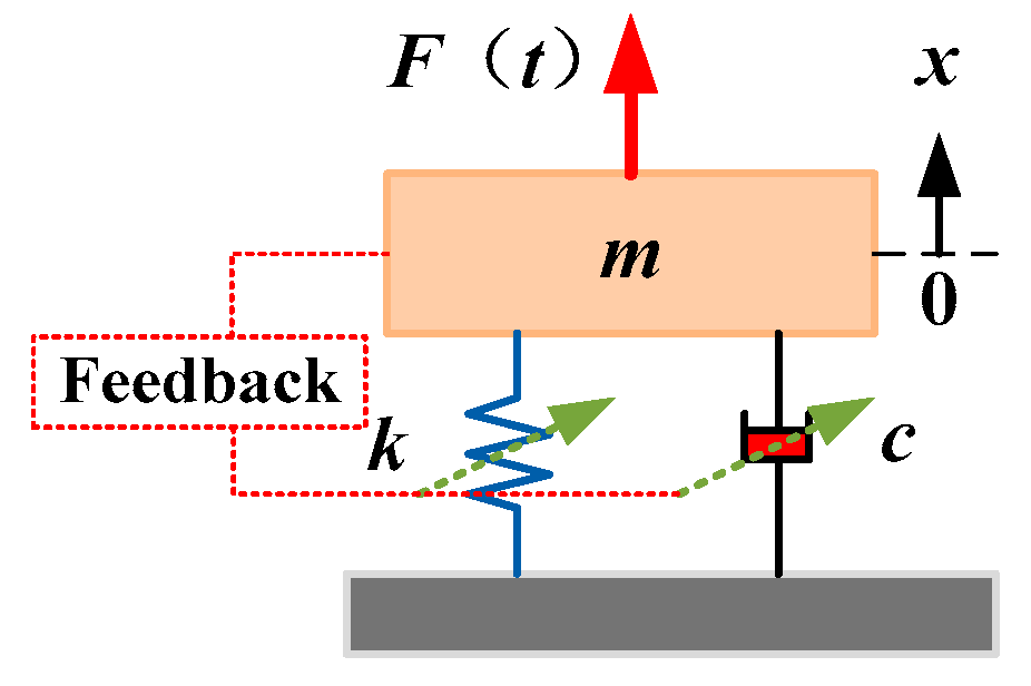
Active vibration isolation technology requires external energy for active control. A feedback system needs to be added to the control system to change the stiffness or damping of the vibration isolator through the processing of feedback information so as to achieve the effect of vibration isolation [
45]. To demonstrate the mechanisms, the working principle of a typical active vibration isolation system is shown in
Figure 4. The bandwidth and parameters of this technology can be adjusted, providing the advantages of fine control and strong adaptability. The feedback control system can be used to adjust the stiffness or damping of the system in time to achieve the purpose of substantial vibration reduction. The vibration isolation effect will be better for vibration in the low–frequency range, which is suitable for high–precision vibration isolation control [
46]. However, it also has the disadvantages of complex structure, low damping reliability, and high cost.
2.2.4. Integrated Active–Passive Vibration Isolation Technology
Integrated active–passive vibration isolation technology combines the advantages of passive and active vibration isolation technology. It can not only isolate relatively high–frequency vibration but also change stiffness and damping parameters, change the control law in time, attenuate low–frequency vibration, broaden the suppression bandwidth, and achieve the ideal effect of vibration reduction. To demonstrate the mechanisms, the typical schematic diagram is shown in
Figure 5 [
13].
In short, according to different vibration isolation requirements, different technologies can be selected to achieve the ideal vibration isolation effect. The advantages and disadvantages of the four vibration isolation technologies are shown in
Table 1.
3. Development of Stewart Platform
The disturbance of micro–vibration in spacecraft has become an important factor affecting the normal operation of high–precision space–borne equipment. Considering the harshness and complexity of vibration reduction requirements in the aerospace environment, the vibration isolation system must have high precision, small mass, strong stiffness, strong bearing capacity, and radiation resistance [
46]. The Stewart damping platform has the advantages of high motion accuracy and large stiffness mass ratio and is widely used as a vibration isolation mechanism in spacecraft.
3.1. Introduction to the Stewart Platform
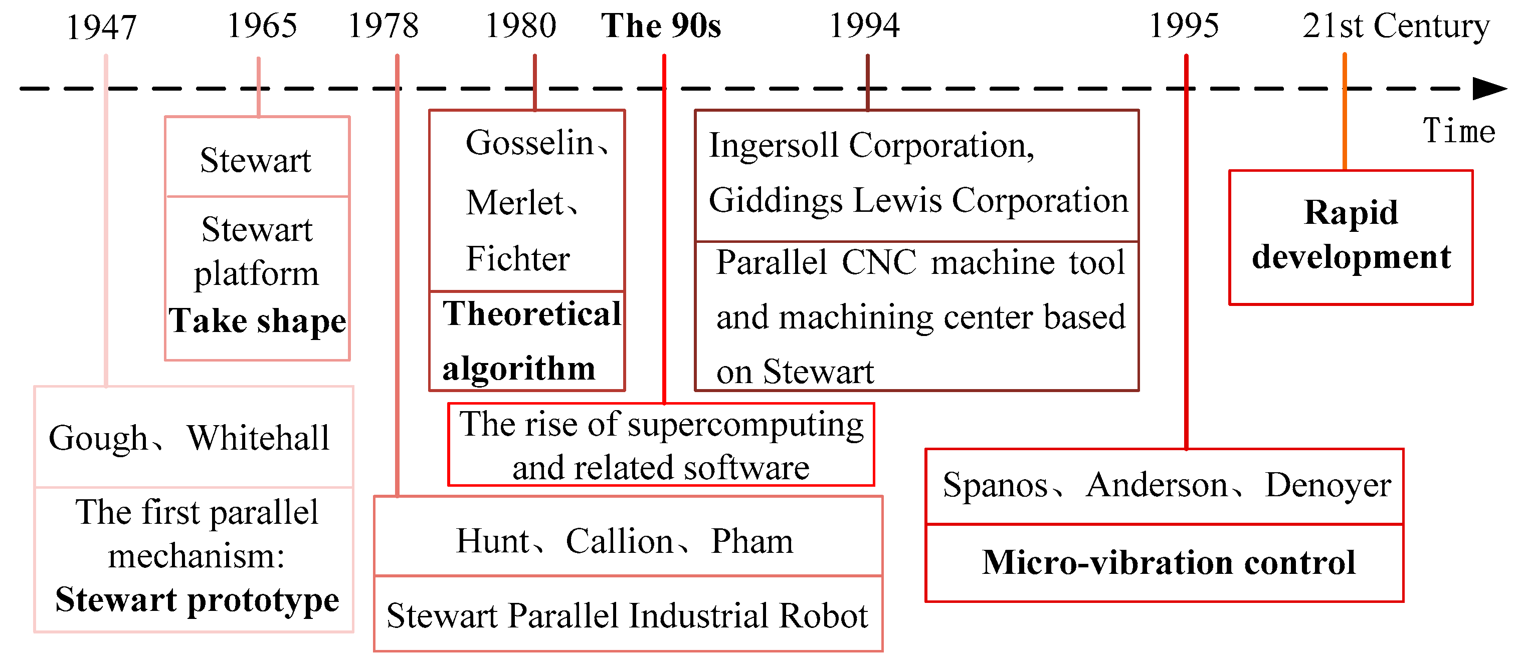
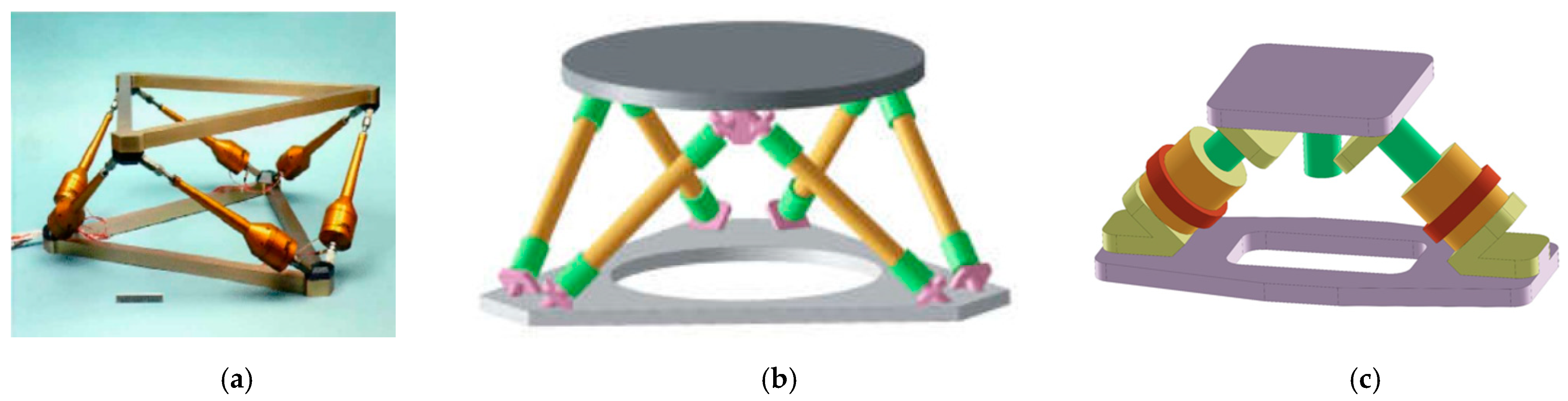
The Stewart damping structure is a classical 6–DOF parallel mechanism. The original structure was proposed by British scholars Gough and Whitehall in 1947 and was mainly used to test the compression of tires in all directions, as shown in
Figure 6 [
47]. In 1965, the German scholar Stewart designed a six–degree–of–freedom flight simulator controlled by six motors in any combination, subsequently setting off a wave of research and development of the parallel mechanism in the academic community, which came to be called the Stewart platform, as shown in
Figure 7 [
48].
Research on the Stewart platform mechanism gradually matured until the 1970s. The specific development process is shown in
Figure 8. In 1978, Australian scholar Hunt designed a parallel robot with high precision, high stiffness, and strong bearing capacity based on the Stewart platform [
31]. Based on this, Callion and Pham first applied the parallel robot manipulator arm based on the Stewart platform to industrial production in 1979 [
31]. After the 1980s, Merlet [
49] and Fichter [
50] conducted research on the kinematics, dynamics, and control methods of the Stewart platform. In the 1990s, with the maturing of computer technology and related software, research and development of the Stewart platform were further promoted. After 1994, Ingersoll and Giddings Lewis in the United States exhibited the hexapod parallel CNC machine tool and VARIAX machining center based on the Stewart platform at the Chicago International Machine Tool Expo, which once again pushed research on the Stewart platform to a new level. Later, with the development of miniaturization technology and the recognition of micro–vibration requirements, research on the Stewart platform was improved for application in the field of aerospace micro–vibration. Since 1995, Spanos [
31], Anderson [
51], Denoyer [
52], and others have used the Stewart platform as a vibration isolation platform between the main body and the interference source so as to achieve the effect of blocking low–frequency micro–vibration. In the 21st century, the Stewart platform has gradually developed in the field of micro–vibration as a vibration isolation platform.
3.2. Stewart Platform Features
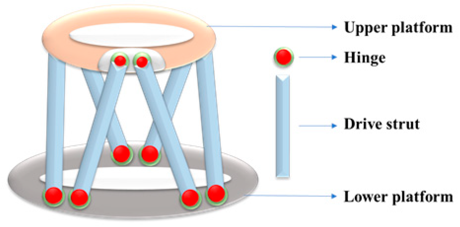
The Stewart platform is composed of an upper platform, a lower platform, and six retractable driving rods connected by hinges, as shown in
Figure 9. Under the twisting action of six retractable driving rods, if the lower platform is fixed, the upper platform can realize three translational movements in the axial direction and three rotations around the axial direction. Compared with the series mechanism, the Stewart platform has the following characteristics [
53,
54]:
- (1)
High stiffness: Six driving rods connect the upper and lower platforms, making the platform stable and rigid;
- (2)
High bearing capacity: As there is high structural stiffness, under the condition of the same mass or volume compared with the series mechanism, a much larger mass can be loaded;
- (3)
High precision: Since the error tends to be average in each driving rod of the parallel mechanism, it will not cause error accumulation, and the structural precision is higher;
- (4)
Perfect dynamic performance: Since each driving rod is arranged on the lower platform, when the platform is moved, the six driving rods will act directly, with high movement efficiency and perfect dynamic performance;
- (5)
Easy to solve: When solving the kinematics of the Stewart platform, it is easy to obtain the inverse solution of equations. The inverse pose solution can be used to obtain the relevant motion parameters.
4. Research Progress of Stewart Platform in the Field of Micro–Vibration
Since the Stewart platform was proposed, many experts at home and abroad have conducted a lot of research on the theory and application. This paper summarizes the theoretical research status and the research progress in the field of micro–vibration.
4.1. Theoretical Research Progress of Stewart Platform
In order to examine the theoretical research progress of the Stewart platform in detail, three aspects of kinematics, dynamics, and control methods are investigated, which are widely used in current research.
4.1.1. Research Progress of Kinematics
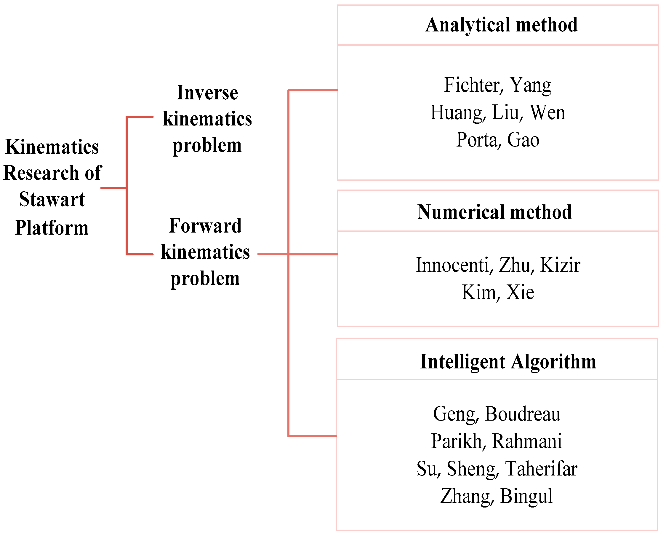
Research on the kinematics of the Stewart platform is conducted mainly to analyze the mapping relationship between the output and input parameters, including pose, velocity, and acceleration. The kinematics problems can be divided into forward and inverse problems [
55,
56]. The forward kinematics problem is to give the input parameters of the platform and solve the six generalized coordinate parameters of the moving platform; the inverse kinematics problem is the opposite.
Due to the strong coupling and nonlinear characteristics of the Stewart platform, it is difficult to obtain a forward analytical solution. However, many researchers still conduct deep research on the forward kinematics solution. The solutions of the forward kinematics problem mainly include the analytical method, numerical method, and intelligent algorithm, as shown in
Figure 10. The research status of each solution is summarized below.
The analytical method mainly includes geometric analysis and algebraic elimination. It is a method of converting kinematic equations to solve polynomials. As early as 1984, Fichter [
50] proposed a method to solve the forward kinematics of the Stewart platform, which also proved that the exact analytical solution could not be obtained. Yang [
57] constructed a set of nonlinear equations to solve six variables of the Stewart platform, and by solving the equations, the forward kinematics problem can be solved. Liu [
58], Wen [
59], Porta [
56], Gao [
60], and others also contributed to finding forward kinematics solutions; however, the analytical method can only give the upper limit of all solutions of forward kinematics, and when the joint variables change, it is impossible to predict the number of corresponding moving platforms.
As the calculation of the one–dimensional search algorithm, three–dimensional search method, and Newton Raphson iterative algebra method is simple and efficient, it is generally used for the numerical solution and is suitable for the solution of the Stewart platform mechanism. In 1993, Innocenti [
61] proposed a one–dimensional search algorithm, which virtualized a driving rod of the Stewart platform mechanism into a support rod with variable length, simplified the overall platform, and solved the new structure with a special method to obtain all real solutions. Subsequently, Zhu [
62], Kizir [
63], Kim [
64], and Xie [
65] solved the forward problem of the Stewart platform by the numerical method. While the numerical algorithm takes a long time, the convergence effect is not good, and the solution result is incomplete, it can avoid having to solve nonlinear higher–order equations.
Around 2000, with developments in science and technology, artificial intelligence algorithms were constructed, and many scholars used these algorithms to solve the forward problem of the Stewart platform. Intelligent algorithms include neural networks, genetic algorithms, particle swarm optimization algorithms, and so on. Geng [
66], Boudreau [
67], Parikh [
68], and Rahmani [
69] applied the neural network method to calculate the forward kinematics of the Stewart platform. Su [
70], Sheng [
71], and Taherifar [
72] used genetic algorithms to optimize the solution, and Zhang [
73] and Bingul [
74] used the particle swarm optimization algorithm to establish a mathematical model of the forward kinematics problem. Using these optimization algorithms directly, the unique solution of the kinematic equation of the Stewart platform can be obtained; however, these algorithms are time–consuming and cannot meet the real–time requirements of vibration reduction.
The different configurations, geometric parameters, and sensor positions of the Stewart platform increase the complexity of the forward kinematics solution. However, the current research is mainly aimed at finding a simplified configuration. Therefore, it is of great significance to study the general forward kinematics solution methods of the Stewart platform.
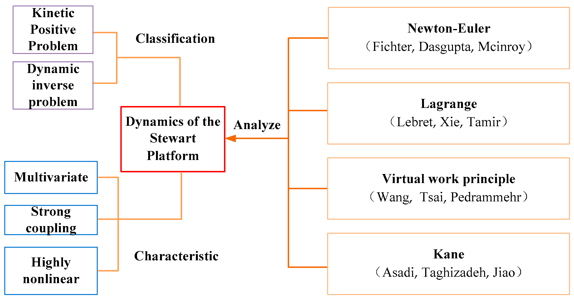
4.1.2. Research Status of Dynamics
Dynamics analysis includes forward and inverse problems. The forward problem of dynamics describes the solution of the pose parameters of the upper platform when the driving force of the lower platform is given. The inverse problem of dynamics is to give the target pose of the upper platform and solve the driving force of the lower platform to achieve the pose. Due to the special structure of the Stewart platform, its dynamic model usually has the characteristics of multivariable, strong coupling, and high nonlinearity [
54].
Common methods for dynamic analysis include the Newton Euler, Lagrange, virtual work principle, and Kane methods, among others, as shown in
Figure 11.
The Newton–Euler method [
75] uses Newton’s second and third laws and Euler’s equations to establish kinematic equations. The process is intuitive and easy to understand, but the derivation and solution are complex. The solution process requires vector operation to describe, and there are many equation groups, redundant and complicated calculations, and low efficiency. The Lagrange method [
76] establishes the relationship between the system energy and generalized coordinates based on the energy of the system as a whole (quantitative kinetic energy and potential energy). The derivation is simple and can clearly express the coupling characteristics between various components, but the amount of calculation is too large to directly calculate the constraint reaction. The virtual work principle method [
77] eliminates the calculation of joint force when establishing pure differential dynamic equations (excluding the binding force of the kinematic pair) and dynamic equations mixed with algebra and differentials (including the reaction force of the kinematic pair constraint), which is easy to program and has high calculation efficiency. The Kane method [
78] is relatively simple in form and avoids the derivation process. When solving the calculation, the velocity bias and angular velocity bias should be introduced, and the vector point product and cross product can be calculated. The generalized active and inertial forces are used to establish the dynamic equation of the system, and the calculation process is relatively abstract.
Fichter [
50] established the dynamic equation of the Stewart platform as early as 1986 but ignored the inertia of the driving rod. After 1998, Dasgupta [
79], McInroy [
80], Khalil [
81], and Fan [
75] successively established the dynamic equation by the Newton Euler method. Combined with vector projection operation, they designed an appropriate coordinate system for the Stewart platform and simplified its derivation process. By 1993, Lebret [
82] and others were the first to establish and analyze the dynamic equation by using the Lagrange method. Later, Xie [
83], Tamir [
76], and Wang [
84] solved the dynamic model by the Lagrange method, which improved the calculation efficiency. Earlier, Wang [
85] and Tsai [
86] used the virtual work principle to solve the inverse dynamic problem of the Stewart platform. Later, Pedrammehr [
77], Ahmadi [
87], Kazezkhan [
26], and others introduced virtual displacement and virtual work for the Stewart platform and adopted the idea that the sum of virtual work carried out by inertial force and driving force is zero to solve the inverse dynamics problem. Asadi [
78], Taghizadeh [
88], Jiao [
89], and Shariatee [
90] used the Kane method to establish the dynamic equation, including the relationship between the speed and acceleration of the driving rod and the platform and solved the dynamic problem of the Stewart platform.
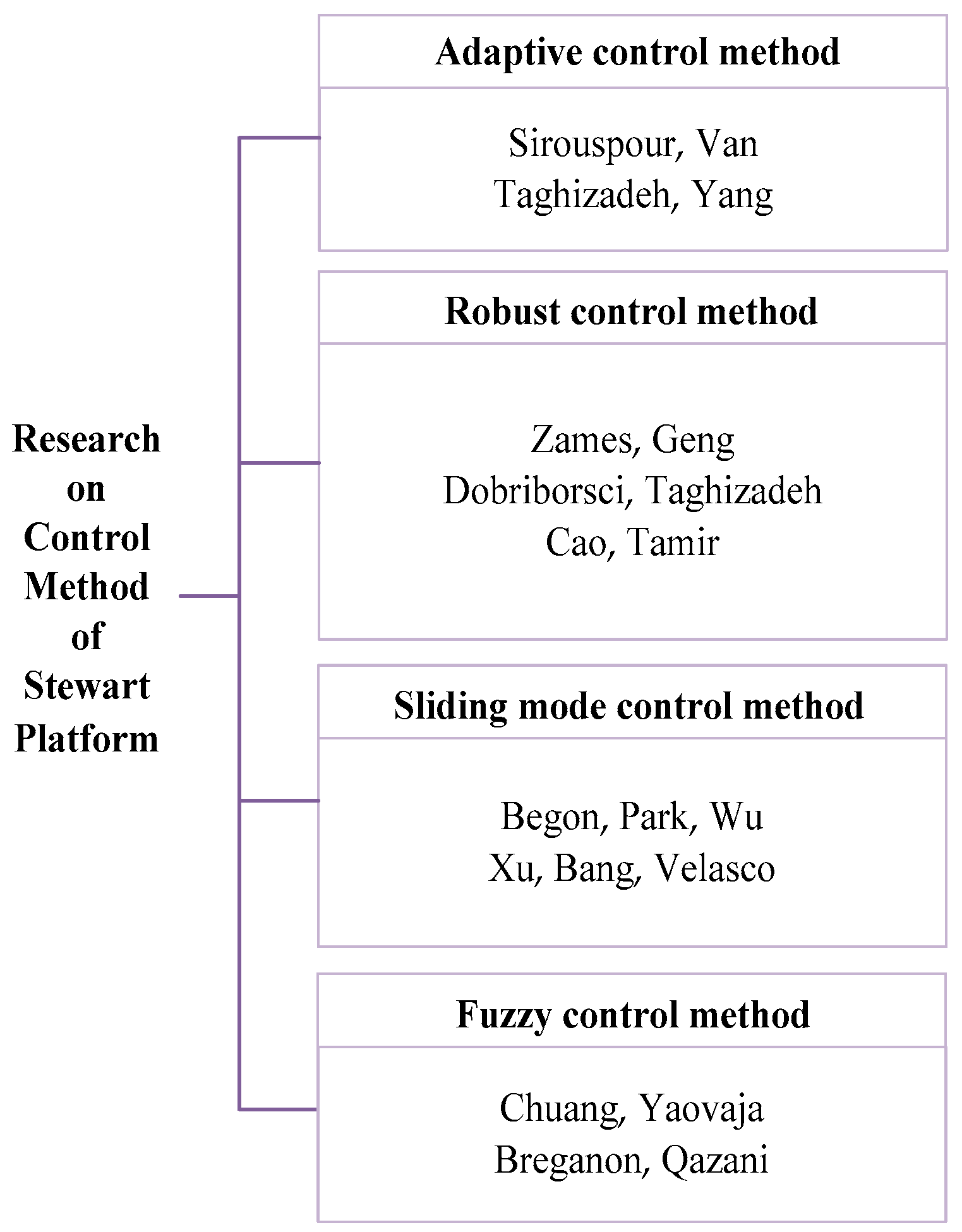
4.1.3. Research Status of Control Methods
After obtaining the kinematic and dynamic model of the Stewart platform, it is necessary to apply various control methods to achieve the desired vibration reduction and isolation effect. At present, the adaptive, robust, sliding mode, and fuzzy control methods are the most widely used active control methods (
Figure 12).
When there is uncertainty in the controlled object or the external environment, or it is constantly changing, the adaptive control method can be used. Sirouspour [
91], Van [
92], Taghizadeh [
88], and Yang [
54] used the adaptive control method to track the error of the Stewart platform and compensate for the parameter uncertainty in the system dynamics. The robust control method was first proposed by Zames in 1981 [
93]. Later, Geng [
94] and others proposed a robust adaptive filtering algorithm for active vibration control and used this algorithm to control the vibration of the cube Stewart platform. The results showed that it could effectively attenuate single frequency interference of 30 dB. Dobriborsci [
95], Taghizadeh [
88], Cao [
96], and Tamir [
76] also applied the robust control method to the Stewart platform model. Sliding mode control is a discontinuous nonlinear control method that can eliminate the parameter perturbation and external interference of the controlled object. The solution is fast, simple, and easy to implement. Since 1995, scholars such as Begon [
97], Park [
98], Wu [
99], Xu [
100], Bang [
101], and Velasco [
102], applying the sliding mode control method, have realized tracking control of the Stewart platform and improved the performance of the system. The fuzzy control method is a control technology that simulates human thinking and decision–making. In 1999, Chuang [
103] studied the stability of the Stewart platform by using fuzzy control. Later, Yaovaja [
104], Breganon [
105], Qazani [
106], and others used the fuzzy PID control algorithm to study the complex asymmetric structure and nonlinear problems of the Stewart platform and improved the calculation efficiency.
The dynamic characteristics of the Stewart platform have a crucial impact on micro–vibration suppression, and the transmission characteristics of its control and interference channels will directly affect its micro–vibration control performance [
107]. Therefore, different control algorithms can be adopted for different models of the Stewart platform to achieve the best effect of vibration reduction and isolation.
4.2. Application Status of Stewart Platform in Aerospace Micro–Vibration
In 1993, NASA first proposed applying the Stewart damping platform in the field of aerospace engineering [
108]. Since then, many scholars have conducted research on micro–vibration control in the aerospace field. The following introduces the structure and performance of different types of Stewart vibration isolation platforms applied to aerospace micro–vibration control.
4.2.1. Rigid Stewart Platform
According to the structural stiffness of the actuator, there are two types of Stewart platforms for aerospace, rigid and flexible. The rigid Stewart platform usually has rigid actuators, generally piezoelectric and magnetostrictive alloy actuators. The rigid actuators are positioned alone or in series with flexible springs [
109]. This platform has the advantages of large actuator stiffness, fast platform response, and good low–frequency vibration isolation performance, but its attitude adjustment ability is relatively weak. The typical rigid Stewart platform for aerospace is described in
Table 2.
Table 2.
Typical rigid Stewart platform.
Table 2.
Typical rigid Stewart platform.
| Year | Research Institution | Platform
Abbreviation | Actuator | Range (mm) | Feedback Sensor | Active Vibration Isolation
Frequency Bandwidth (Hz) |
|---|
| 1995 | Intelligent Automation | HAVI | Giant magnetostrictive Actuator | ±0.127 | Payload, acceleration sensor, force sensor | 10~250 |
| 1996 | CSA Engineering | UQP | Solenoid actuator | ±0.02 | Payload
detection wave | 3~100 |
| 2000 | CSA Engineering | SUITE | Piezoelectric
actuator | ±0.02 | Payload
detection wave | 3~200 |
| 2001 | Free University of Brussels | ULB | Piezoelectric
actuator | ±0.025 | Force sensor, payload | 4~90 |
| 2001 | CSA Engineering | PH1 | Piezoelectric
ceramic actuator | ±6.35 | Payload
detection wave | 1~100 |
| 2006 | Fujita Corporation | GMS/AIR | Giant magnetostrictive actuator and air spring | – | Acceleration sensor | 1~80 |
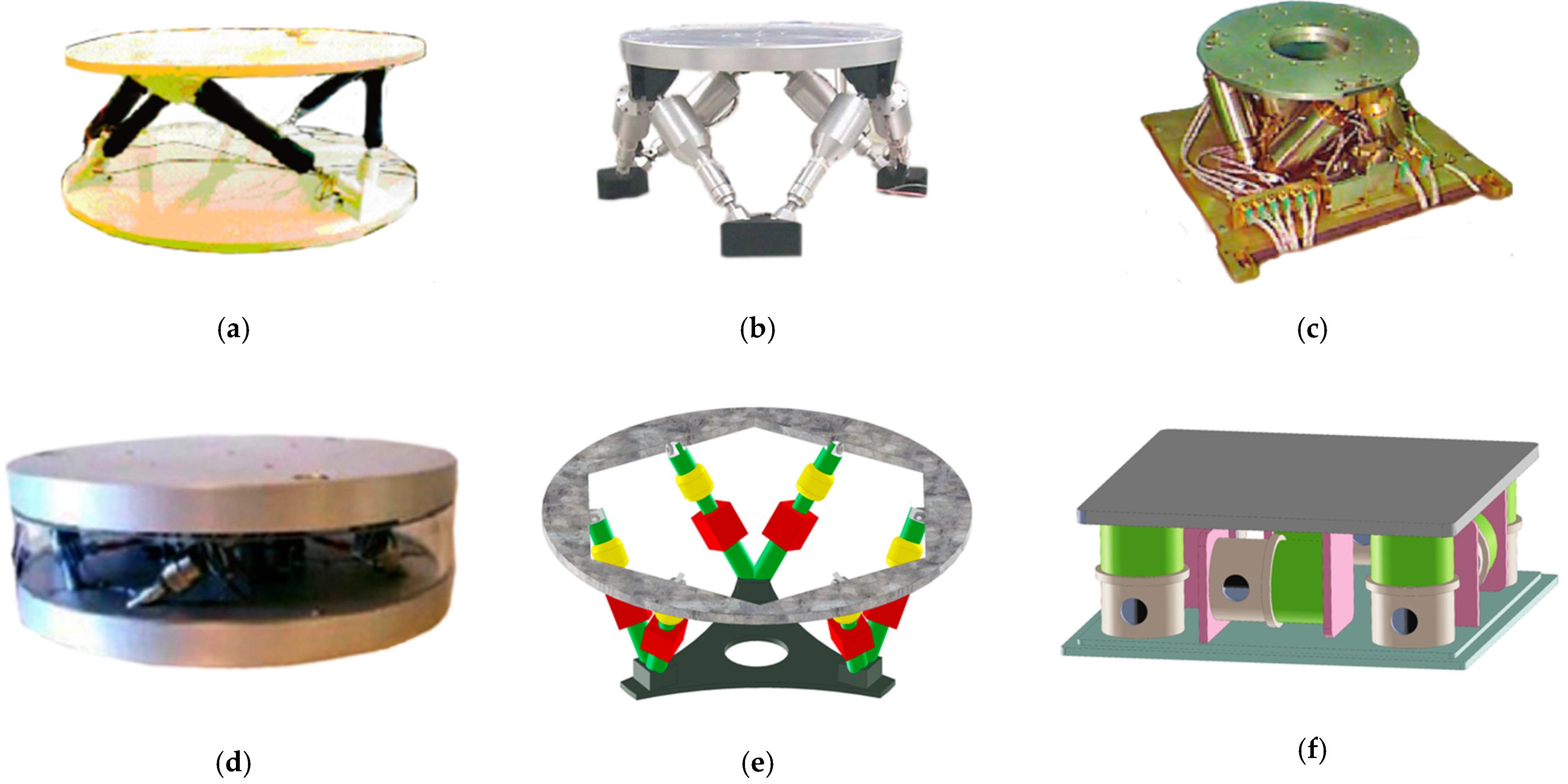
In 1995, Geng [
94], of the Intelligent Automation company, proposed for the first time the HAVI vibration isolation Stewart platform in the form of a mutually orthogonal "cubic" structure, applied to the field of aerospace micro–vibration (
Figure 13a), and developed and designed the corresponding control algorithm to reduce the coupling effect of the structure. The HAVI vibration isolation platform adopts a new type of Terfenol–D magnetostrictive alloy as the actuator, and the motion range is ±0.127 mm. With the use of a two–layer control system structure combined with local force feedback control and robust adaptive filter control for active vibration isolation, the platform’s vibration attenuation can reach 15 dB in the frequency range of 10–250 Hz. After 1996, CSA also developed a UQP vibration damping platform for aerospace based on the six–axis Stewart platform (
Figure 13b) [
111]. The driving rod of the UQP vibration isolation platform adopts a rigid electromagnetic actuator, and a detector for measuring motion is installed on the driving rod. This novel series method is used to realize active/passive vibration isolation in each strut. Tests show that the platform has 20 dB vibration attenuation at a bandwidth of 100 Hz. However, when the system is matched with highly flexible infrastructure, the isolation performance will be reduced [
110].
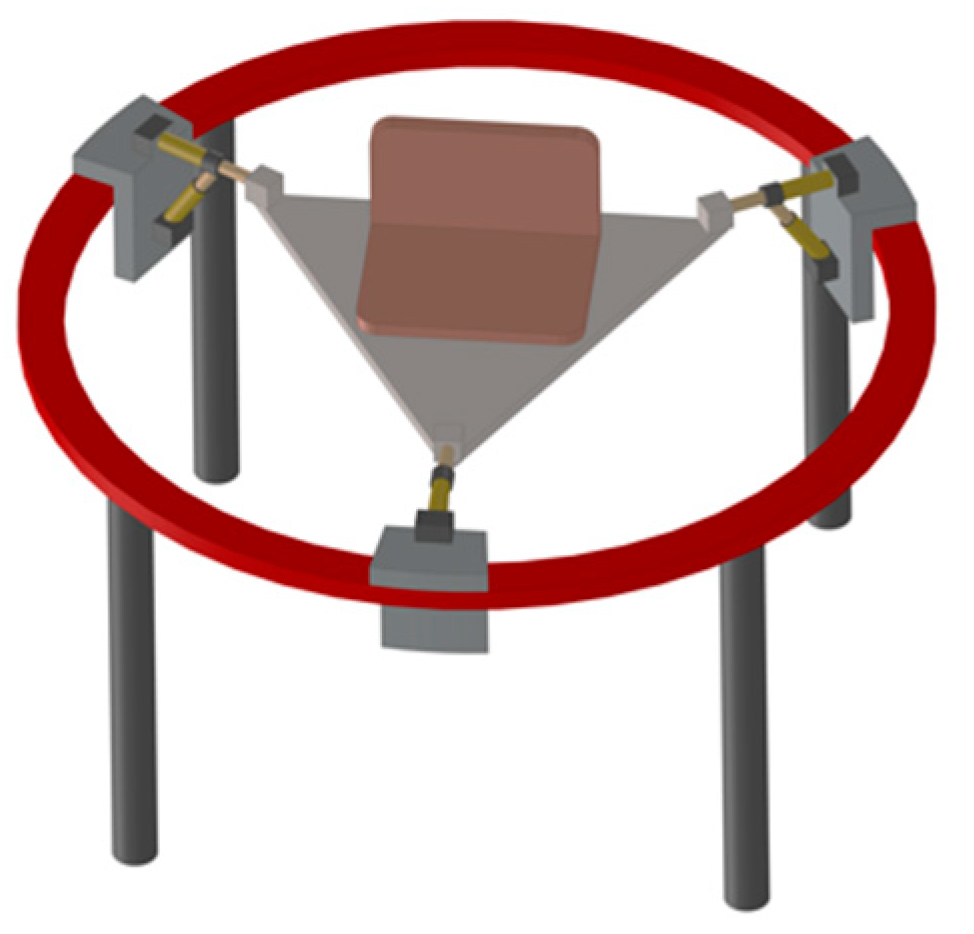
At the beginning of the 21st century, in order to further solve the interference of aerospace micro–vibration, the SUITE platform developed by CSA Engineering (
Figure 13c) [
51], the ULB hyperstatic platform at the Universit é Libre De Bruxelles (ULC) (
Figure 13d) [
112], and the Ph1 rigid Stewart platform by CSA (
Figure 13e) [
51] used piezoelectric actuators as the drivers of the platform, with the corresponding feedback sensors and active control algorithms, providing the spacecraft platform with a large motion range and high motion accuracy to achieve the ideal effect of vibration isolation.
In 2006, Fujita Corporation developed a six–degree–of–freedom micro–vibration control system using a giant magnetostrictive actuator and air spring (
Figure 13f) [
113]. The platform has a stable structure, a perfect micro–vibration isolation effect, and fast response speed. Tests show that the vibration isolation platform can successfully isolate disturbance in the range of less than 80 Hz.
4.2.2. Flexible Stewart Platform
The flexible Stewart platform usually uses soft actuators, such as voice coil motors, in parallel with soft springs [
109]. With vibration isolation and attitude adjustment functions, micro–vibration suppression can be realized, but the stroke of the actuator is large. The typical flexible Stewart platform for aerospace is described in
Table 3.
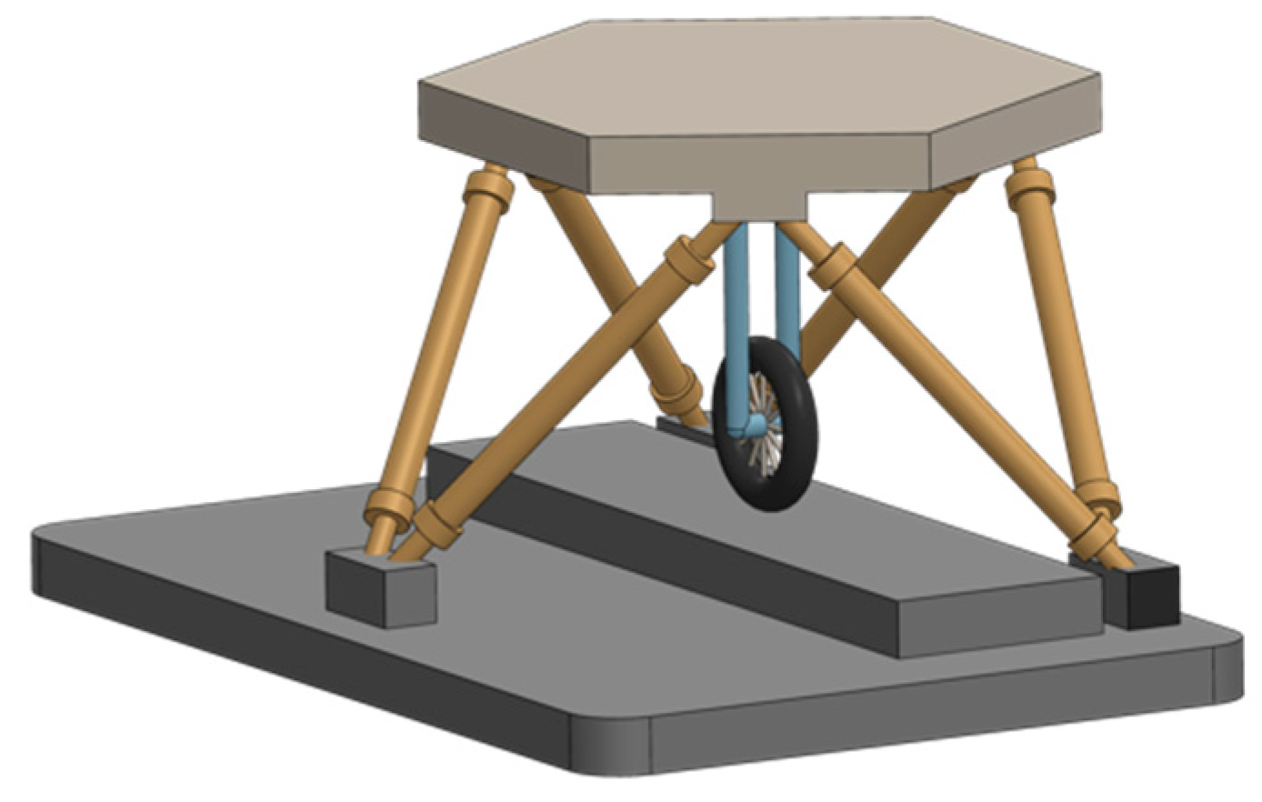
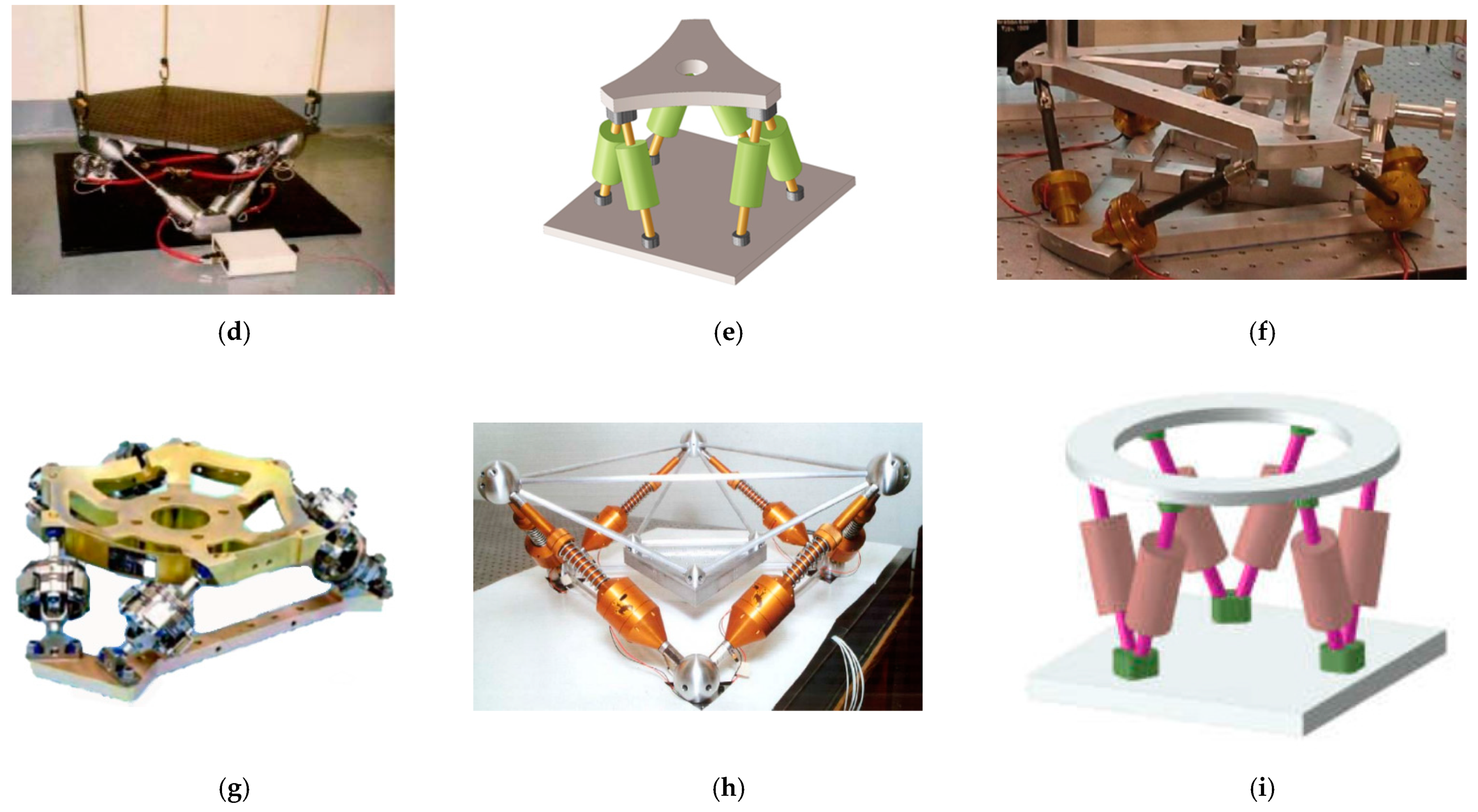
In 1995, the Jet Propulsion Laboratory (JPL) designed a flexible active vibration isolation platform based on the cubic Stewart platform structure to isolate the vibrations of flywheels, cryogenic coolers, and other noisy machines on spacecraft (
Figure 14a) [
114]. It is made of six electromagnetic voice coil brakes and soft springs in parallel, and a force sensor is installed at the bottom of each driving rod to measure its axial transmission rate. The test results show that compared with passive vibration isolation technology, the vibration isolation attenuates the transmission rate of the device at low frequency (7–100 Hz) by 10 times. Later, Honeywell Inc (Honeywell International, Morristown, NJ, USA). developed the first–generation D–struts flexible Stewart platform (
Figure 14b) [
115] and the second–generation MVIS Stewart platform (
Figure 14c) [
116]. The HT/UW vibration isolation platform designed by Hood Technology Corporation (HT) and the University of Washington (UW) (
Figure 14d) [
117], which was successfully applied to spacecraft, the PPH flexible Stewart platform made by Taranti (
Figure 14e) [
118], and the ULC flexible Stewart platform designed by ULC (
Figure 14f) [
119] all use voice coil motor as the flexible actuator. Combined with the corresponding feedback sensor and active control algorithm, they can isolate low–frequency interference on spacecraft and have the functions of vibration isolation and attitude adjustment.
In 1998, in order to reduce the influence of micro–vibration on a spacecraft, the TWR company designed an RWIA flexible Stewart platform with a damping rod and spring (
Figure 14g) [
120]. The damping is supplied by viscoelastic materials, and the spring provides the necessary stiffness. It can produce −12 dB frequency attenuation at a frequency of 9 Hz, suppress the vibration interference of an airborne momentum wheel, and meet the mechanical environment requirements for the normal operation of optical load equipment. Later, UW developed a Stewart–like vibration isolation platform using flexible joints for micro–vibration control of a spacecraft (
Figure 14h) [
114]. A spring is added to each driving column to isolate some high–frequency vibration, and the positive feedback of force is used to improve the closed–loop robustness and reduce the system sensitivity so as to further improve the vibration isolation effect. The Naval Postgraduate School (NPS) designed the NPS flexible Stewart platform with an electro–magnetic soft actuator to isolate micro–vibration on spacecraft (
Figure 14i) [
121]. This platform has the characteristics of large driving displacement and perfect vibration isolation effect but requires additional support structure during launch.
5. Future Development Prospects
The Stewart damping platform has the advantages of high stiffness, high bearing capacity, good dynamic performance and easy solution. It can be used as a micro–vibration isolation device for high–precision spacecraft. Although considerable research results have been achieved, research on the Stewart platform can still be improved and optimized. The future development of the Stewart platform in the field of aerospace micro–vibration control can be discussed from the following aspects.
- (1)
Fast kinematics solution
The kinematics solution of the Stewart platform is still a research hotspot. Although some existing artificial intelligence algorithms can obtain a kinematic solution, they are time–consuming and do not meet the application requirements of real–time vibration reduction. With the rapid development of artificial intelligence technology in recent years, whether the emerging artificial intelligence algorithms, such as machine learning and deep learning algorithms, can effectively solve the problem is a question worth in–depth discussion. Therefore, using emerging artificial intelligence algorithms to quickly solve the kinematics model has become one of the important research directions for the Stewart platform.
- (2)
Optimization of the Stewart platform control strategy
When the Stewart platform requires a large vibration isolation bandwidth, integrated active/passive vibration isolation technology needs to be adopted. With the progress and development of science and technology over time, the components and products used for active vibration isolation have matured, and the electronic system has been improved. However, active vibration isolation control technology has not reached the ideal state, and the corresponding control algorithm is not very mature. Therefore, in designing the appropriate optimal control strategy, how to enable the Stewart platform to carry out effective vibration isolation control in the whole frequency domain has also become a focus of research.
- (3)
Material/structural design of Stewart platform
As a typical 6–DOF parallel mechanism, the structural design of the Stewart platform should meet specific workspace requirements. At present, the commonly used actuator structures include spring, voice coil motor, magnetostriction, tablet actuator, and so on. However, for vibration damping/isolation of spacecraft in reality, in order to meet the requirements of vibration damping/isolation, the structure is expected to have the ability of large–directional adjustment so as to play a role in the normal operation of spacecraft in all directions and all time periods. This puts forward the requirement of variable stiffness for the Stewart platform. With the development of smart material technology, whether smart materials with variable stiffness and excellent performance, such as shape memory polymer, can be applied to the new structure has become an important research topic. Therefore, the omni–directional and all–time optimized material/structure design of the Stewart platform will also become the research direction in the future.
- (4)
Integrated design of Stewart platform
The existing Stewart platform needs a variety of sensors and controllers to assist in normal vibration reduction/isolation work. This leads to the complexity of the platform and the diversity of its communication interfaces. However, spacecraft are now developing in the direction of miniaturization. It is especially important to study a lightweight, miniaturized, universal, and integrated Stewart platform. With the development of new multi–functional materials and the maturity of 4D printing technology, new specific multi–functional materials, such as electro–responsive intelligent material and low–melting–point alloy material, can be used to prepare a multi–functional, integrated Stewart platform with variable stiffness with a 4D printer. With the maturity of 4D printing technology, it will become a research hotspot.
6. Conclusions
In this paper, the research status of the Stewart vibration isolation platform in the field of aerospace micro vibration is reviewed. Although scholars in various countries have made some research achievements in this field, there are still some problems worth discussing and improving. Through a literature search, it was found the solution algorithm and control strategy of the Stewart platform still have room for improvement and development. In particular, with the development of artificial intelligence technology, some new algorithms can be used as new technologies for fast solutions and control of the Stewart platform. In addition, with the development of smart materials and 4D printing technology, and the use of low–melting–point alloys as variable stiffness materials, some smart materials with variable stiffness and excellent performance can be used as the matrix material of the new Stewart platform. The new integrated omni–directional, multi–functional platform with full frequency band and variable stiffness could be prepared by 4D printing technology. On the basis of meeting the basic requirements of vibration isolation/reduction, it could also support the current requirements of spacecraft miniaturization. With further maturity of the research on the Stewart vibration isolation platform, it will play a positive role in promoting the development of high–precision and high–reliability spacecraft.
Author Contributions
Conceptualization, Z.H., X.F. and L.Z.; validation, Z.H., Y.Z. (Yeqing Zhu) and Z.L.; formal analysis, Y.Z. (Yeqing Zhu); investigation, Z.Y., Y.W. and Y.Z. (Yan Zhang); resources, Z.H.; data curation, P.W.; writing—original draft preparation, Z.H.; writing—review and editing, Y.Z. (Yan Zhang), X.F. and L.Z.; visualization, Z.H.; supervision, P.W.; project administration, P.W.; funding acquisition, Z.L. and L.Z. All authors have read and agreed to the published version of the manuscript.
Funding
This research was funded by the National Natural Science Foundation of China (grant no. 52083291) and the National Natural Science Foundation of China (No. 12072027).
Institutional Review Board Statement
Not applicable.
Informed Consent Statement
Not applicable.
Data Availability Statement
Not applicable.
Conflicts of Interest
The authors declare that they have no known competing financial interests or personal relationships that could have appeared to influence the work reported in this paper.
References
- Ulgen, D.; Ertugrul, O.L.; Ozkan, M.Y. Measurement of ground borne vibrations for foundation design and vibration isolation of a high–precision instrument. Measurement 2016, 93, 385–396. [Google Scholar] [CrossRef]
- Kamesh, D.; Pandiyan, R.; Ghosal, A. Passive vibration isolation of reaction wheel disturbances using a low frequency flexible space platform. J. Sound Vib. 2012, 331, 1310–1330. [Google Scholar] [CrossRef]
- Xu, Z.D.; Huang, X.H.; Xu, F.H.; Yuan, J. Parameters optimization of vibration isolation and mitigation system for precision platforms using non–dominated sorting genetic algorithm. Mech. Syst. Signal Process. 2019, 128, 191–201. [Google Scholar] [CrossRef]
- Anderson, E.H.; Sater, J.M. SPIE smart structures product implementation award: A review of the first ten years. In Proceedings of the Industrial and Commercial Applications of Smart Structures Technologies, San Diego, CA, USA, 18–23 March 2007. [Google Scholar]
- Wang, Y.W.; Sun, H.B.; Hou, L.L. Event–triggered anti–disturbance attitude and vibration control for T–S fuzzy flexible spacecraft model with multiple disturbances. Aerosp. Sci. Technol. 2021, 117, 1270–9638. [Google Scholar] [CrossRef]
- Winthrop, M.F.; Cobb, R.G. Survey of state–of–the–art vibration isolation research and technology for space applications. In Proceedings of the Smart Structures and Materials 2003, San Diego, CA, USA, 2–6 March 2003. [Google Scholar]
- Zheng, W.; Chen, H.; Luo, Z. Multi–Input–Multi–Output Continuous Swept–Sine Vibration Test Realization by Inverse Multistep Prediction Model. Shock. Vib. 2020, 2020, 8869802. [Google Scholar] [CrossRef]
- Wang, G.Y.; Zhou, D.Q.; Zhao, Y. Data analysis of micro–vibration on–orbit measurement for remote sensing satellite. J. Astronaut. 2015, 36, 261–267. [Google Scholar]
- Zhou, W.Y.; Li, D.X.; Luo, Q.; Liu, K. Analysis and testing of micro–vibrations produced by momentum wheel assemblies. Chin. J. Aeronaut. 2012, 25, 640–649. [Google Scholar] [CrossRef] [Green Version]
- Bialke, B. A complication of reaction wheel induced spacecraft disturbances. In Proceedings of the 20th Annual American Astronautical Society Guidance and Control Conference, Breckenridge, CO, USA, 5–9 February 1997. [Google Scholar]
- Chen, J.P.; Cheng, W.; Li, X. Modeling and simulation of the disturbance torque generated by solar array drive assembly. J. Vib. Shock 2017, 36, 188–194. [Google Scholar] [CrossRef]
- Cao, Y.; Cao, D.; Wei, J.; Huang, W. Modeling for solar array drive assembly system and compensating for the rotating speed fluctuation. Aerosp. Sci. Technol. 2019, 84, 131–142. [Google Scholar] [CrossRef]
- Liu, C.; Jing, X.; Daley, S.; Li, F. Recent advances in micro–vibration isolation. Tetrahedron Asymmetry 2015, 56–57, 55–80. [Google Scholar] [CrossRef]
- Jedrich, N.; Zimbelman, D.; Turczyn, M.; Sills, J.; Voorjees, C.; Clapp, B.; Brumfield, M. Cryo cooler induced micro–vibration disturbances to the Hubble space telescope. Nasa Sti/Recon Tech. Rep. N 2002, 2, 1–7. [Google Scholar]
- Zhang, Q.J.; Wang, G.Y.; Zheng, G.T. Micro–vibration attenuation methods and key techniques for optical remote sensing satellite. J. Astronaut. 2015, 36, 125–132. [Google Scholar]
- Feng, Z.; Cui, Y.; Yang, X.; Qin, J. Micro–vibration issues in integrated design of high resolution optical remote sensing satellites. In Springer Proceedings in Physics, Proceedings of the 3rd International Symposium of Space Optical Instruments and Applications, Beijing, China, 26–29 June 2016; Springer: Cham, Switzerland, 2017; pp. 459–469. [Google Scholar]
- Ullio, R.; Marta, F. Artemis micro–vibration environment prediction. Spacecraft Structures, Materials and Mechanical Testing. In Proceedings of the European Conference, Braunschweig, Germany, 4–6 November 1998. [Google Scholar]
- Sun, H.Y.; Zhang, L.; Chen, S.B.; Gu, S.; Li, J. Design and experimental study of the combined vibration isolation device for flywheel micro–vibration. J. Astronaut. 2020, 41, 1288–1294. [Google Scholar]
- Yun, H.; Liu, L.; Li, Q.; Li, W.; Tang, L. Development of an isotropic Stewart platform for telescope secondary mirror. Mech. Syst. Signal Process. 2019, 127, 328–344. [Google Scholar] [CrossRef]
- Du, L.F.; Ji, L.W.; Luo, Y.J.; Shao, S.B.; Xu, M.L. Simulation and experiment of an active–passive isolator for micro–vibration control of spacecraft. In Proceedings of the 2020 15th Symposium on Piezoelectrcity, Acoustic Waves and Device Applications (SPAWDA), Zhengzhou, China, 16–19 April 2021; pp. 227–232. [Google Scholar]
- Ji, J.C.; Luo, Q.; Ye, K. Vibration control based metamaterials and origami structures: A state–of–the–art review. Mech. Syst. Signal Process. 2021, 161, 107945. [Google Scholar] [CrossRef]
- Xu, G.N.; Huang, H.; Li, W.P.; Ma, W. Active vibration control of space flexible structure using Stewart platform as active base. J. Astronaut. 2015, 36, 438–445. [Google Scholar]
- Dasgupta, B.; Mruthyunjaya, T.S. The Stewart platform manipulator: A review. Mech. Mach. Theory 2000, 35, 15–40. [Google Scholar] [CrossRef]
- Nag, A.; Safar, V.; Bandyopadhyay, S. A uniform geometric–algebraic framework for the forward kinematic analysis of 6–6 Stewart platform manipulators of various architectures and other related 6–6 spatial manipulators. Mech. Mach. Theory 2021, 155, 104090. [Google Scholar] [CrossRef]
- Nag, A.; Bandyopadhyay, S. Singularity–free spheres in the position and orientation workspaces of Stewart platform manipulators. Mech. Mach. Theory 2021, 155, 104041. [Google Scholar] [CrossRef]
- Kazezkhan, G.; Xiang, B.; Wang, N.; Yusup, A. Dynamic modeling of the Stewart platform for the Nan Shan Radio Telescope. Adv. Mech. Eng. 2020, 12, 1687814020940072. [Google Scholar] [CrossRef]
- Zhao, Y.; Gao, F. Dynamic formulation and performance evaluation of the redundant parallel manipulator. Robot. Comput.–Integr. Manuf. 2009, 25, 770–781. [Google Scholar] [CrossRef]
- Tunc, L.T.; Shaw, J. Investigation of the effects of Stewart platform–type industrial robot on stability of robotic milling. Int. J. Adv. Manuf. Technol. 2016, 87, 189–199. [Google Scholar] [CrossRef] [Green Version]
- Zhang, Y.; Huang, H.; Li, S.; Li, J.; He, L. Event–triggered zeroing dynamics for motion control of Stewart platform. J. Frankl. Inst. 2020, 357, 6453–6470. [Google Scholar] [CrossRef]
- Hardt, M.; Villa, J.R.; Cocho, D.; Urmston, P.; Gracia, Ó. Simulation and control of an active Stewart platform for docking and berthing of space vehicles. In Proceedings of the 57th International Astronautical Congress, Valencia, Spain, 2–6 October 2006; p. C1.3.01. [Google Scholar]
- Spanos, J.; Rahman, Z.; Blackwood, G. A soft 6–axis active vibration isolator. In Proceedings of the 1995 American Control Conference–ACC’95, Seattle, WA, USA, 21–23 June 1995. [Google Scholar]
- Xu, Z.; Weng, C. Track–position and vibration control simulation for strut of the Stewart platform. J. Zhejiang Univ. Sci. A 2013, 14, 281–291. [Google Scholar] [CrossRef] [Green Version]
- Yang, X.L.; Wu, H.T.; Li, Y.; Chen, B. Dynamic isotropic design and decentralized active control of a six–axis vibration isolator via Stewart platform. Mech. Mach. Theory 2017, 117, 244–252. [Google Scholar] [CrossRef]
- Bacher, J.P.; Joseph, C.; Clavel, R. Flexures for high precision robotics. Ind. Robot. Int. J. 2002, 29, 349–353. [Google Scholar] [CrossRef]
- Hesselbach, J.; Wrege, J.; Raatz, A.; Becker, O. Aspects on design of high precision parallel robots. Assem. Autom. 2004, 24, 47–57. [Google Scholar] [CrossRef]
- Zhang, X.; Hsi, W.C.; Yang, F.; Wang, Z.; Sheng, Y.; Sun, J.; Zhou, R. Development of an isocentric rotating chair positioner to treat patients of head and neck cancer at upright seated position with multiple nonplanar fields in a fixed carbon–ion beamline. Med. Phys. 2020, 47, 2450–2460. [Google Scholar] [CrossRef]
- Wang, C.; Xie, X.; Chen, Y.; Zhang, Z. Investigation on active vibration isolation of a Stewart platform with piezoelectric actuators. J. Sound Vib. 2016, 383, 1–19. [Google Scholar] [CrossRef]
- Zhang, Z.; Aglietti, G.S.; Zhou, W. Micro–vibrations induced by a cantilevered wheel assembly with a soft–suspension system. AIAA J. 2011, 49, 1067–1079. [Google Scholar] [CrossRef] [Green Version]
- Lu, S.; Jiang, Z.H.; Liu, Y.; Chen, M.H. Research on towing dynamics and control method of space tether system considering solar panel vibration. J. Astronaut. 2021, 42, 458–466. [Google Scholar]
- Ma, C.L.; Liu, Y.; Chen, M.; Liu, L.; Liang, W.G. A combined control method of Chang’e–4 relay satellite’s mission orbit keeping maneuver and momentum wheel unloading. J. Astronaut. 2020, 41, 389–397. [Google Scholar]
- Li, L.; Tan, L.; Kong, L.; Yang, H.B. Flywheel micro–vibration characters of a high resolution optical satellite. J. Vibroengineering 2017, 19, 3981–3993. [Google Scholar]
- Zhang, H.; Li, S.Q.; Liu, S.P.; Wang, Y.; Zhang, Z. An analysis method of effect of cryocooler micro–vibration on space camera imaging. J. Astronaut. 2017, 38, 1226–1233. [Google Scholar]
- Duan, P.F.; Guan, X.; Zheng, G.T.; Zhong, M.; Ou, Z.W.; Yu, Z.W.; Shao, Y.K. Design and ground tests of the ultra quiet stable device for a space spectrum interferometer. J. Astronaut. 2018, 39, 624–631. [Google Scholar]
- Liu, Y.; Matsuhisa, H.; Utsuno, H. Semi–active vibration isolation system with variable stiffness and damping control. J. Sound Vib. 2008, 313, 16–28. [Google Scholar] [CrossRef] [Green Version]
- Wang, X.M.; Zhou, W.Y.; Xun, G.B.; Wu, Z.G. Dynamic shape control of piezoelectric structures with vibration suppression. J. Astronaut. 2017, 38, 185–191. [Google Scholar]
- Zeng, H.Z.; Dong, Y.Z.; Sheng, C.; Zhang, L. Design of lightweight and high precision structure of Chang’e 5 ascender. J. Astronaut. 2021, 42, 953–960. [Google Scholar]
- Gough, V.E.; Whitehall, S.G. Universal tyre test machine. In Proceedings of the 9th International Congress FISITA, London, UK, 7–10 May 1962; pp. 117–137. [Google Scholar]
- Stewart, D. A platform with six degrees of freedom. Proc. Inst. Mech. Eng. 1965, 180, 371–386. [Google Scholar] [CrossRef]
- Merlet, J.P. Parallel Manipulators Part I: Theory Design, Kinematics, Dynamics and Control; INRIA Research Report No.646; INRIA: Paris, France, 1987; pp. 1–10. [Google Scholar]
- Fichter, E.F. A stewart platform–based manipulator: General theory and practical construction. Int. J. Robot. Res. 1986, 5, 157–182. [Google Scholar] [CrossRef]
- Anderson, E.H.; Fumo, J.P.; Erwin, R.S. Satellite ultraquiet isolation technology experiment (SUITE). In Proceedings of the 2000 IEEE Aerospace Conference, Big Sky, MT, USA, 25 March 2000. [Google Scholar]
- Denoyer, K.K.; Erwin, R.S.; Ninneman, R.R. Advanced smart structures flight experiments for precision spacecraft. Acta Astronaut. 2000, 47, 389–397. [Google Scholar] [CrossRef]
- Lu, Z.Q.; Wu, D.; Ding, H.; Chen, L.Q. Vibration isolation and energy harvesting integrated in a Stewart platform with high static and low dynamic stiffness. Appl. Math. Model. 2021, 89, 249–267. [Google Scholar] [CrossRef]
- Yang, X.L.; Wu, H.T.; Chen, B.; Wu, H.T.; Chen, B.; Kang, S.Z.; Cheng, S.L. Dynamic modeling and decoupled control of a flexible Stewart platform for vibration isolation. J. Sound Vib. 2019, 439, 398–412. [Google Scholar] [CrossRef]
- Virgil Petrescu, R.V.; Aversa, R.; Apicella, A.; MirMilad, M.; Kozaitis, S.; Abu–Lebdeh, T.; Petrescu, F.I.T. Inverse kinematics of a Stewart platform. J. Mechatron. Robot. 2018, 2, 45–59. [Google Scholar] [CrossRef]
- Porta, J.M.; Thomas, F. Yet another approach to the Gough–Stewart platform forward kinematics. In Proceedings of the 2018 IEEE International Conference on Robotics and Automation (ICRA), Brisbane, Australia, 21–25 May 2018; pp. 974–980. [Google Scholar]
- Yang DC, H.; Lee, T.W. Feasibility study of a platform type of robotic manipulators from a kinematic viewpoint. J. Mech. Des. 1984, 106, 191–198. [Google Scholar] [CrossRef]
- Liu, K.; Fitzgerald, J.M.; Lewis, F.L. Kinematic analysis of a Stewart platform manipulator. Ind. Electron. IEEE Trans. 1993, 40, 282–293. [Google Scholar] [CrossRef]
- Wen, F.; Liang, C. Displacement analysis of the 6–6 Stewart platform mechanisms. Mech. Mach. Theory 1994, 29, 547–557. [Google Scholar] [CrossRef]
- Gao, C.; Yang, Z.; Zheng, S.; Cong, D. An algorithm for real–time forward kinematics of 6–degree–of–freedom parallel mechanisms. Proc. Inst. Mech. Eng. Part I J. Syst. Control. Eng. 2017, 232, 109–120. [Google Scholar] [CrossRef]
- Wei, F.; Wei, S.; Zhang, Y.; Liao, Q. Algebraic solution for the forward displacement analysis of the general 6–6 Stewart mechanism. Chin. J. Mech. Eng. 2016, 29, 56–62. [Google Scholar] [CrossRef]
- Zhu, Q.; Zhang, Z. An efficient numerical method for forward kinematics of parallel robots. IEEE Access 2019, 7, 128758–128766. [Google Scholar] [CrossRef]
- Kizir, S.; Bingül, Z. Design and development of a Stewart platform assisted and navigated transsphenoidal surgery. Turk. J. Electr. Eng. Comput. Sci. 2019, 27, 961–972. [Google Scholar] [CrossRef]
- Kim, Y.S.; Shi, H.; Dagalakis, N.; Marvel, J.; Cheok, G. Design of a six–DOF motion tracking system based on a Stewart platform and ball–and–socket joints. Mech. Mach. Theory 2019, 133, 84–94. [Google Scholar] [CrossRef] [PubMed]
- Xie, B.; Dai, S.; Liu, F. A lie group–based iterative algorithm framework for numerically solving forward kinematics of gough–Stewart platform. Mathematics 2021, 9, 757. [Google Scholar] [CrossRef]
- Geng, Z.; Haynes, L. Neural network solution for the forward kinematics problem of a Stewart platform. In Proceedings of the 1991 IEEE International Conference on Robotics and Automation, Sacramento, CA, USA, 9–11 April 1991; pp. 2650–2655. [Google Scholar]
- Boudreau, R.; Turkkan, N. Solving the forward kinematics of parallel manipulators with a genetic algorithm. J. Robot. Syst. 1996, 13, 111–125. [Google Scholar] [CrossRef]
- Parikh, P.J.; Lam, S.S.Y. A hybrid strategy to solve the forward kinematics problem in parallel manipulators. IEEE Trans. Robot. 2005, 21, 18–25. [Google Scholar] [CrossRef]
- Rahmani, A.; Faroughi, S. Application of a novel elimination algorithm with developed continuation method for nonlinear forward kinematics solution of modular hybrid manipulators. Robotica 2020, 38, 1963–1983. [Google Scholar] [CrossRef]
- Su, Y.X.; Duan, B.Y.; Zheng, C.H. Genetic design of kinematically optimal fine tuning Stewart platform for large spherical radio telescope. Mechatronics 2001, 11, 821–835. [Google Scholar] [CrossRef]
- Liu, S.; Li, W.; Du, Y.; Fang, L. Forward kinematics of the Stewart platform using hybrid immune genetic algorithm. In Proceedings of the 2006 International Conference on Mechatronics and Automation, Luoyang, China, 25–28 June 2006; pp. 2330–2335. [Google Scholar]
- Taherifar, A.; Najafi, E.; Nahvi, A.; Najafi, F. Kinematic optimization of Stewart platform for simulators using genetic algorithm. In Proceedings of the 6th Annual IEEE Conference on Automation Science and Engineering, Toronto, ON, Canada, 21–24 August 2013; pp. 123–129. [Google Scholar]
- Zhang, S.; Yuan, X.; Docherty, P.D.; Yang, K.; Li, C. An improved particle swarm optimization algorithm and its application in solving forward kinematics of a 3–DoF parallel manipulator. Proc. Inst. Mech. Eng. Part C J. Mech. Eng. Sci. 2020, 235, 896–907. [Google Scholar] [CrossRef]
- Bingul, Z.; Karahan, O. Real–time trajectory tracking control of Stewart platform using fractional order fuzzy PID controller optimized by particle swarm algorithm. Ind. Robot. Int. J. Robot. Res. Appl. 2021, 49, 708–725. [Google Scholar] [CrossRef]
- Fan, X.; Ma, J.; Ji, R. Integrated Dynamic Modeling for a Stewart Platform. In Proceedings of the 2018 37th Chinese Control Conference (CCC), Wuhan, China, 25–27 July 2018; pp. 1844–1848. [Google Scholar]
- Tamir, T.S.; Xiong, G.; Tian, Y.; Xiong, G. Passivity based control of Stewart platform for trajectory tracking. In Proceedings of the 2019 14th IEEE Conference on Industrial Electronics and Applications (ICIEA), Xi’an, China, 19–21 June 2019; pp. 988–993. [Google Scholar]
- Pedrammehr, S.; Nahavandi, S.; Abdi, H. Closed–form dynamics of a hexarot parallel manipulator by means of the principle of virtual work. Acta Mech. Sin. 2018, 34, 883–895. [Google Scholar] [CrossRef]
- Asadi, F.; Sadati, S.H. Full dynamic modeling of the general Stewart platform manipulator via Kane’s method. Iran. J. Sci. Technol. Trans. Mech. Eng. 2018, 42, 161–168. [Google Scholar] [CrossRef]
- Dasgupta, B.; Mruthyunjaya, T.S. A Newton–Euler formulation for the inverse dynamics of the Stewart platform manipulator. Mech. Mach. Theory 1998, 33, 1135–1152. [Google Scholar] [CrossRef]
- McInroy, J.E. Dynamic modeling of flexure jointed hexapods for control purposes. In Proceedings of the 1999 IEEE International Conference on Control Applications (Cat. No. 99CH36328), Kohala Coast, HI, USA, 22–27 August 1999; Volume 1, pp. 508–513. [Google Scholar]
- Khalil, W.; Ibrahim, O. General Solution for the Dynamic Modeling of Parallel Robots. J. Intell. Robot. Syst. Theory Appl. 2007, 49, 19–37. [Google Scholar] [CrossRef] [Green Version]
- Lebret, G.; Liu, K.; Lewis, F.L. Dynamic analysis and control of a Stewart platform manipulator. J. Robot. Syst. 1993, 10, 629–655. [Google Scholar] [CrossRef]
- Xie, B.; Dai, S. Optimal trajectory generation for Stewart platform using discrete mechanics and optimal control. In Proceedings of the 2018 13th IEEE Conference on Industrial Electronics and Applications (ICIEA), Wuhan, China, 31 May–1 June 2018; pp. 980–985. [Google Scholar]
- Wang, M.; Hu, Y.; Sun, Y.; Ding, J.; Pu, H.; Yuan, S.; Zhao, J.; Peng, Y.; Xie, S.; Luo, J. An adjustable low–frequency vibration isolation Stewart platform based on electromagnetic negative stiffness. Int. J. Mech. Sci. 2020, 181, 105714. [Google Scholar] [CrossRef]
- Wang, J.; Gosselin, C.M. A New Approach for the Dynamic Analysis of Parallel Manipulators. Multibody Syst. Dyn. 1998, 2, 317–334. [Google Scholar] [CrossRef]
- Tsai, L.W. Solving the Inverse Dynamics of a Stewart–Gough Manipulator by the Principle of Virtual Work. J. Mech. Des. 2000, 122, 3–9. [Google Scholar] [CrossRef]
- Ahmadi, S.S.; Rahmanii, A. Nonlinear model predictive control of a Stewart platform based on improved dynamic model. Int. J. Theor. Appl. Mech. 2020, 5, 18–26. [Google Scholar]
- Taghizadeh, M.; Yarmohammadi, M.J. Development of a self–tuning PID controller on hydraulically actuated Stewart platform stabilizer with base excitation. Int. J. Control Autom. Syst. 2018, 16, 2990–2999. [Google Scholar] [CrossRef]
- Jiao, J.; Wu, Y.; Yu, K.; Zhao, R. Dynamic modeling and experimental analyses of Stewart platform with flexible hinges. J. Vib. Control 2019, 25, 151–171. [Google Scholar] [CrossRef]
- Shariatee, M.; Akbarzadeh, A. Optimum dynamic design of a Stewart platform with symmetric weight compensation system. J. Intell. Robot. Syst. 2021, 103, 66. [Google Scholar] [CrossRef]
- Sirouspour, M.R.; Salcudean, S.E. Nonlinear control of hydraulic robots. Robot. Autom. IEEE Trans. 2001, 17, 173–182. [Google Scholar] [CrossRef] [Green Version]
- Van Nguyen, T.; Ha, C. RBF neural network adaptive sliding mode control of rotary Stewart platform. In Lecture Notes in Computer Science, Proceedings of the International Conference on Intelligent Computing, Wuhan, China, 15–18 August 2018; Springer: Cham, Switzerland, 2018; pp. 149–162. [Google Scholar]
- Zhou, K.; Doyle, J.C.; Glover, K. Robust and optimal control. In Proceedings of the 35th IEEE Conference on Decision and Control, Kobe, Japan, 13 December 2002. [Google Scholar]
- Geng, Z.J.; Pan, G.G.; Haynes, L.S.; Wada, B.K.; Garba, J.A. An intelligent control system for multiple degree–of–freedom vibration isolation. J. Intell. Mater. Syst. Struct. 1995, 6, 787–800. [Google Scholar] [CrossRef]
- Dobriborsci, D.; Kolyubin, S.; Margun, A. Robust control system for parallel kinematics robotic manipulator. IFAC–Pap. Line 2018, 51, 62–66. [Google Scholar] [CrossRef]
- Cao, X.; Zhao, W.; Zhao, H.; Wang, H.; Yang, W.; Zhang, B. 6–PSS precision positioning Stewart platform for the space telescope adjustment mechanism. In Proceedings of the 2018 IEEE International Conference on Mechatronics and Automation (ICMA), Jilin, China, 5–8 August 2018; pp. 487–492. [Google Scholar]
- Begon, P.; Pierrot, F.; Dauchez, P. Fuzzy sliding mode control of a fast parallel robot. In Proceedings of the IEEE International Conference on Robotics and Automation, Nagoya, Japan, 21–27 May 1995; pp. 1178–1183. [Google Scholar]
- Park, M.K.; Lee, M.C.; Go, S.J. The design of sliding mode controller with perturbation observer for a 6–DOF parallel manipulator. In Proceedings of the IEEE International Symposium on Industrial Electronics, Pusan, Korea, 12–16 June 2000; pp. 1502–1507. [Google Scholar]
- Wu, D.S.; Gu, H.B. Adaptive sliding control of six–DOF flight simulator motion platform. Chin. J. Aeronaut. 2007, 20, 425–433. [Google Scholar]
- Xu, J.; Wang, Q.; Lin, Q. Parallel robot with fuzzy neural network sliding mode control. Adv. Mech. Eng. 2018, 10, 425–433. [Google Scholar] [CrossRef] [Green Version]
- Bang, H.; Lee, Y.S. Implementation of a ball and plate control system using sliding mode control. IEEE Access 2018, 6, 32401–32408. [Google Scholar] [CrossRef]
- Velasco, J.; Calvo, I.; Barambones, O.; Venegas, P.; Napole, C. Experimental validation of a sliding mode control for a Stewart platform used in aerospace inspection applications. Mathematics 2020, 8, 2051. [Google Scholar] [CrossRef]
- Chung, I.F.; Chang, H.H.; Lin, C.T. Fuzzy control of a six–degree motion platform with stability analysis. In Proceedings of the 1999 IEEE International Conference on Systems, Man, and Cybernetics (Cat. No.99CH37028), Tokyo, Japan, 12–15 October 1999. [Google Scholar]
- Yaovaja, K. Ball balancing on a Stewart platform using fuzzy supervisory PID visual servo control. In Proceedings of the 2018 5th International Conference on Advanced Informatics: Concept Theory and Applications (ICAICTA), Krabi, Thailand, 14–17 August 2018; pp. 170–175. [Google Scholar]
- Breganon, R.; Montezuma MA, F.; de Souza, M.M.; Lemes, R.C.; Belo, E.M. A Comparative Analysis of PID, Fuzzy and H Infinity Controllers Applied to a Stewart Platform. Int. J. Adv. Eng. Res. Sci. 2019, 6, 25–32. [Google Scholar] [CrossRef] [Green Version]
- Qazani, M.R.C.; Asadi, H.; Bellmann, T.; Perdrammehr, S.; Mohamed, S.; Nahavandi, S. A new fuzzy logic based adaptive motion cueing algorithm using parallel simulation–based motion platform. In Proceedings of the 2020 IEEE International Conference on Fuzzy Systems (FUZZ–IEEE), Glasgow, UK, 19–24 July 2020; pp. 1–8. [Google Scholar]
- Yuan, L. Spacecraft intelligent autonomous control technology toward uncertain environment. J. Astronaut. 2021, 42, 839–849. [Google Scholar]
- Haynes, L.S. Six Degree of Freedom Active Vibration Damping for Space Applications; NASA: Washington, DC, USA, 2 May 1993.
- Boltosi, A.; Chiriac, A.; Nagy, R.; Bereteu, L. Stewart platform. Application of smart fluid dampers in this field. Ann. Oradea Univ. Fascicle Manag. Technol. Eng. 2008, VII, 107–114. [Google Scholar]
- Thayer, D.; Campbell, M.; Vagners, J.; von Flotow, A. Six–axis vibration isolation system using soft actuators and multiple sensors. J. Spacecr. Rocket. 2002, 39, 206–212. [Google Scholar] [CrossRef]
- Chen, H.J.; Bishop, R.; Agrawal, B. Payload pointing and active vibration isolation using hexapod platforms. In Proceedings of the 44th AIAA/ASME/ASCE/AHS/ASC Structures, Structural Dynamics, and Materials Conference, Norfolk, VA, USA, 7–10 April 2003; p. 1643. [Google Scholar]
- Hanieh, A.A.; Preumont, A. Frequency Variation for the Purpose of Vibration Isolation. In Proceedings of the 2006 IEEE International Conference on Mechatronics, Budapest, Hungary, 3–5 July 2006. [Google Scholar]
- Nakamura, Y.; Nakayama, M.; Yasuda, M.; Fujita, T. Development of active six–degrees–of–freedom micro–vibration control system using hybrid actuators comprising air actuators and giant magnetostrictive actuators. Smart Mater. Struct. 2006, 15, 1133. [Google Scholar] [CrossRef]
- Lin, H.; McInroy, J.E. Disturbance attenuation in precise hexapod pointing using positive force feedback. Control Eng. Pract. 2006, 14, 1377–1386. [Google Scholar] [CrossRef]
- Davis, L.P.; Carter, D.R.; Hyde, T.T. Second–generation hybrid D–strut. In Proceedings of the Smart Structures and Materials 1995: Passive Damping, San Diego, CA, USA, 5 May 1995. [Google Scholar]
- Dan, Q.; Boyd, J.; Buchele, P.; Self, R.; Davis, T.; Hintz, T.L.; Jacobs, J.H. Miniature vibration isolation system for space applications. In Proceedings of the SPIE’s 8th Annual International Symposium Smart Structures and Materials, Newport Beach, CA, USA, 14 June 2001. [Google Scholar]
- Hauge, G.S.; Campbell, M.E. Sensors and control of a space–based six–axis vibration isolation system. J. Sound Vib. 2004, 269, 913–931. [Google Scholar] [CrossRef]
- Taranti, C.; Agrawal, B.; Cristi, R. An efficient algorithm for vibration suppression to meet pointing requirements of optical payloads. In Proceedings of the AIAA Guidance, Navigation, and Control Conference and Exhibit, Montreal, QC, Canada, 6–9 August 2001. [Google Scholar]
- Preumont, A.; Horodinca, M.; Romanescu, I.; de Marneffe, B.; Avraam, M.; Deraemaeker, A.; Bossens, F.; Abu Hanieh, A.M. A six–axis single–stage active vibration isolator based on Stewart platform. J. Sound Vib. 2007, 300, 644–661. [Google Scholar] [CrossRef] [Green Version]
- Pendergast, K.J.; Schauwecker, C.J. Use of a passive reaction wheel jitter isolation system to meet the advanced X–ray astrophysics facility imaging performance requirements, Space Telescopes and Instruments V. SPIE 1998, 3356, 1078–1094. [Google Scholar]
- Chen, H.J.; Hospodar, E.; Agrawal, B. Development of a hexapod laser–based metrology system for finer optical beam pointing control. In Proceedings of the 22nd AIAA International Communications Satellite Systems Conference & Exhibit 2004 (ICSSC), Monterey, CA, USA, 9–12 May 2004. [Google Scholar]
| Publisher’s Note: MDPI stays neutral with regard to jurisdictional claims in published maps and institutional affiliations. |
© 2022 by the authors. Licensee MDPI, Basel, Switzerland. This article is an open access article distributed under the terms and conditions of the Creative Commons Attribution (CC BY) license (https://creativecommons.org/licenses/by/4.0/).


 ,
, 


