Article

The Flying and Adhesion Robot Based on Approach and Vacuum

1
School of Computer Science and Engineering, Nanjing University of Science and Technology, Nanjing 210094, China
2
School of Mechanical Engineering, Nanjing University of Science and Technology, Nanjing 210094, China
*
Author to whom correspondence should be addressed.
Aerospace 2022, 9(5), 228; https://doi.org/10.3390/aerospace9050228
Submission received: 6 March 2022 / Revised: 13 April 2022 / Accepted: 19 April 2022 / Published: 21 April 2022
(This article belongs to the Special Issue Applications of Drones)

Abstract

:
The conventional flying and adhesion robot adsorbs on the wall by controlling the attitude angle to generate a horizontal-direction force combined with the negative-pressure device at the target position. However, when the robot is in contact with the wall, the wall will generate reaction forces and tilting moments on the robot, which increases the complexity of modeling and controlling the adsorption process. Therefore, inspired by perching mechanisms that geckos and tree frogs can use to jump and adsorb to vertical surfaces such as tree trunks, we propose a natural method based on approach adsorption. The method uses a suitable approaching velocity to achieve stable adsorption at the desired position. We investigate the effects of approach velocity, vacuum-pump flow rate and wall material on the adsorption performance. Furthermore, we design a unidirectional-approach-adsorption system and heading controller and establish a contact and negative-pressure model. The relevant parameters of the adsorption system are identified, and the ground-collision experiments and flight experiments for the flying and adhesion robot were carried out to validate the proposed method.

1. Introduction

Rotorcraft drones are widely used in natural-disaster monitoring, aerial photography, battlefield reconnaissance, plant protection and other fields due to their light weight, portability, hovering ability and other advantages. They can carry a variety of mission loads (camera (RGB-D, binocular and thermal imaging), LIDAR, millimeter wave radar, spraying system, etc.). However, the power consumption of rotorcraft drones is generally high, and rotorcraft drones have shorter flight times than fixed-wing drones. In recent years, some VTOL (vertical take-off and landing) solutions have been proposed, which combine the fixed-wing and rotorcraft characteristics. They are capable of vertical take-off and landing, using the fixed-wing mode in fast flight to extend range. Because the fixed-wing mode cannot hover, the short flight-time problem is not completely solved. Moreover, we previously proposed a flying and adhesion robot, which can both adsorb on the surface of objects to perform tasks and move quickly by flight [1,2].

1.1. Motivation

Conventional flying and adhesion robots mainly adsorb on the surface by controlling the robot to move slowly to the specified adsorption position and by changing its attitude to obtain a horizontal force so that the sealing skirt of the suction cup fully contacts with the surface of the wall and generates negative pressure attaching the robot to the wall. In order to solve the conflict between the horizontal component force of the robot and the attitude of the suction cup, it is necessary to increase the degrees of freedom of the suction cup and possibly the force sensor.
However, such a control method needs to consider the attitude performance of the robot, because while the robot is in contact with the wall, the wall will generate reaction forces and tilting moments in the pitch direction of the body coordinate system. At this time, it is necessary for the robot to consider the influence of this external force in the controller and react in time, otherwise the robot will generate a larger pitch angle. When this pitch angle exceeds a certain threshold, the air pressure near the wall will further increase this tilting moment, which will make the robot go beyond its control ability and cause overturning. This control method puts higher demands on the modeling and control of the robot. Although the risk of overturning can be reduced by adding additional protection devices such as struts, the struts undoubtedly increase the weight of the robot, especially when they are far from the center of mass, and must be compensated by more propeller lift.
Observing the existing perching mechanisms in nature, animals such as geckos and tree frogs use a controlled-impact approach strategy when they are jumping to vertical surfaces such as tree trunks. Therefore, we propose a flying and adhesion robot based on approach and vacuum. The robot is firmly adsorbed on the wall surface by controlling the approach velocity. We keep the body attitude horizontal during the contact with the wall, and the sealing skirt of the suction cups is in full contact with the wall surface without applying additional force to the wall surface.
Furthermore, we change the position of the suction cup and make it higher than the center of gravity of the robot. The collision will cause them to rotate along the direction of gravity even if a certain pitch moment is generated. Due to the existence of the side adsorption-support bar, this moment is likely to lead to a secondary collision. However, this collision will be absorbed by the vibration-absorptive material on the support bar to ensure that the machine will not overturn.

1.2. Related Work

The issue of rotorcraft drones in contact with the wall environment has been studied for many years. Albert Albers et al. started a study in 2010 for quadrotor UAVs for high-altitude cleaning tasks [3], by vertically mounting an additional rotor to provide thrust against the wall. Dongjun Lee et al. studies the use of quadrotor UAVs to operate lightweight rigid tools such as screwdrivers, the position-tracking control of the end of the tool and rotation control of the tool [4]. Paper [5] presents a hybrid pose/wrench control framework that allows the quadrotor to directly contact the environment and maintain stable motion upon contact. The proposed work explicitly considers the underdrive characteristics of the quadrotor and uses a moment observer that can estimate the moment generated by the quadrotor using only quadrotor inputs and attitude measurements. A versatile control architecture for aerial robots in interactive tasks is presented [6]. The control architecture uses variable impedance control. Varying the the apparent impedance as well as the interaction forces of the controlled aerial robot during contact. The feasibility and effectiveness of the proposed controller are demonstrated by quadrotor experiment results. Seul Jung has conducted a lot of research work on impedance control and proposed a scenario of impedance force control based on a disturbance observer which is applied to a quadrotor UAV to screw a light bulb on the ceiling [7].
Paper [8] describes a flying and adhesion robot that performs collisional adsorption by adding a dry-adsorption gripper. The papers based on collision rather than slow contact with the wall mainly focus on the adverse effects of wall collisions and recovering from them collision. For example, paper [9] uses a compliant arm design that allows free flight while allowing a passive degree of freedom to absorb the impact. A Hall sensor-based collision-detection and characterization method are proposed, as well as a new recovery-control method that generates and tracks a smooth trajectory after a collision has occurred. In Paper [10], protective bumpers are installed around the rotors and the collision between the airframe and the vertical wall is modeled. The simulation and experimental preliminary results verify the possibility and conditions for recovery from the collision. A collision-recovery method is proposed for collision recovery of a quadrotor based on a protective cushion [11]. It is validated by comprehensive Monte Carlo collision-bumper simulations, showing the feasibility of recovery from challenging collision scenarios. Paper [12] compares the accuracy of attitude estimation of various attitude-estimation methods during normal flight and wall collision. The results show that the UKF-based algorithm performed the best in all scenarios and the adaptive algorithm showed a slight but not significant improvement in performance during collision recovery. Paper [13] investigates the control problem of recovering a quadrotor after collision with a pole. Paper [14] proposes a fast collision-detection method based on IMU and potential field theory for recovery after the collision.
Robots based on adsorption methods such as negative pressure are mainly found in special robots such as wall-climbing robots. In the papers [15,16,17], suction-cup modeling is performed, and the effective area, adsorption force and friction force are calculated. Moreover, flight adsorption can be achieved through control and planning. In Paper [18], control and planning algorithms are used to enable an underdriven quadrotor with a downward gripper to stay on an inclined surface while satisfying the drive and sensing constraints.
Because the robot can generate a stable and continuous force during the top surface adsorption, the flying and adhesion robot based on the approach and vacuum is mainly applied to the side adsorption.

1.3. Main Contributions

In this paper, we propose a flying and adhesion robot based on approach adsorption, which can make negative-pressure adsorption by horizontal contact with the wall at a certain velocity, and can recover from the adsorption failure. The specific contributions are as follows:
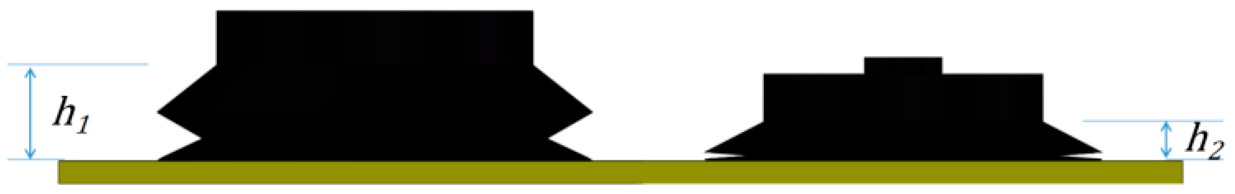
  • We analyzed the reasons for adsorption failure or overturning, and optimized the structure of the flying and adhesion robot.
  • In this paper, the approach-adsorption model of the flying and adhesion robot was established, which solves the optimization-velocity problem when the system model parameters change. To the author’s knowledge, this model is proposed for the first time.
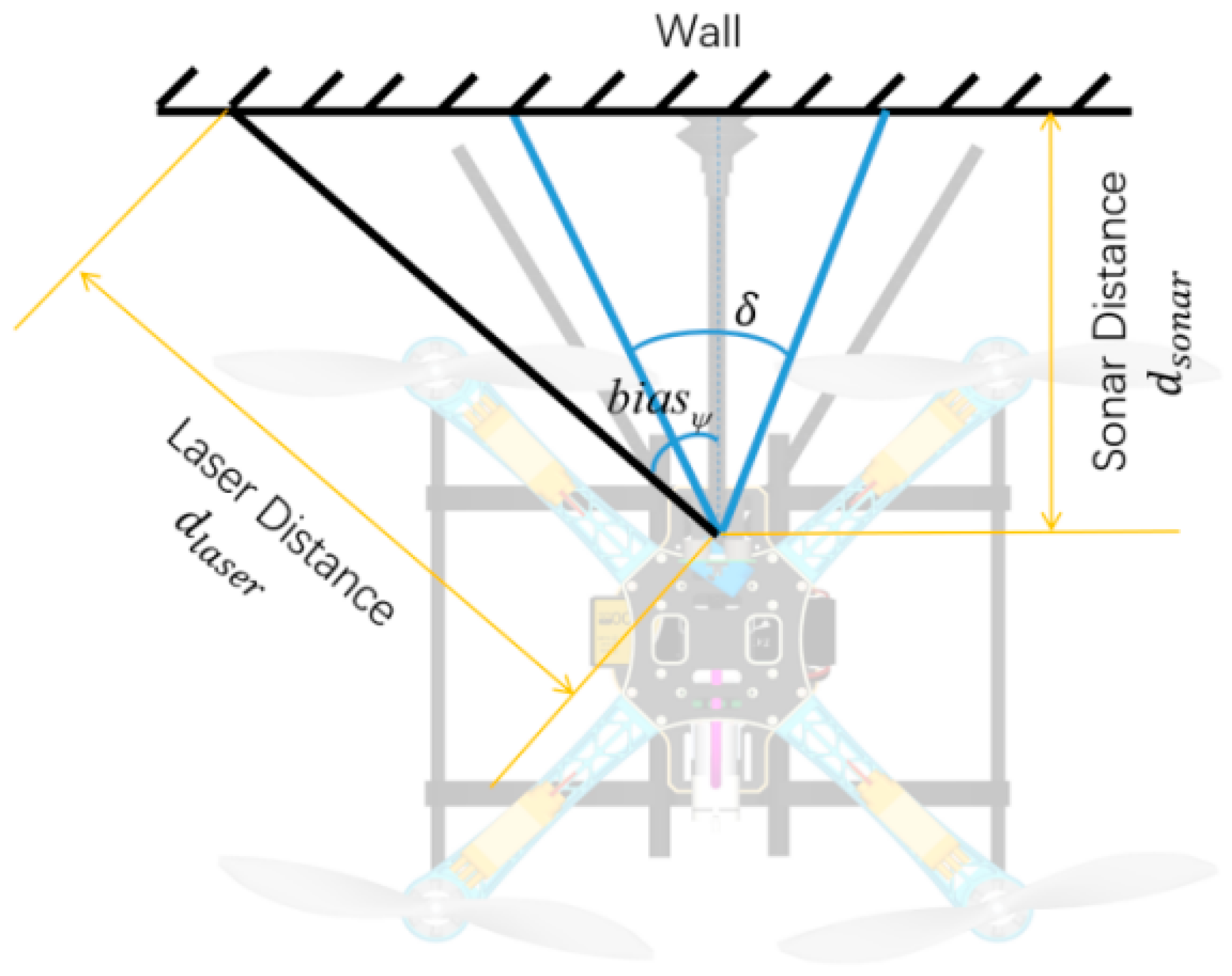
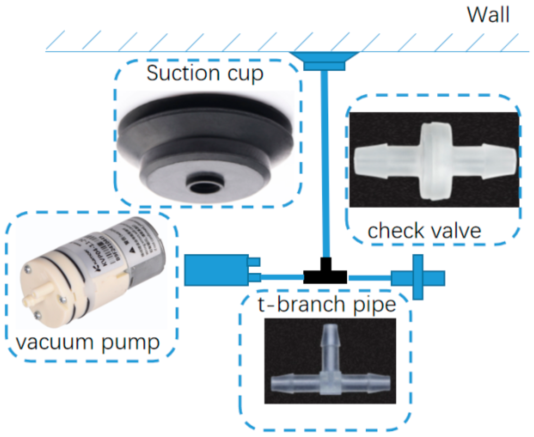
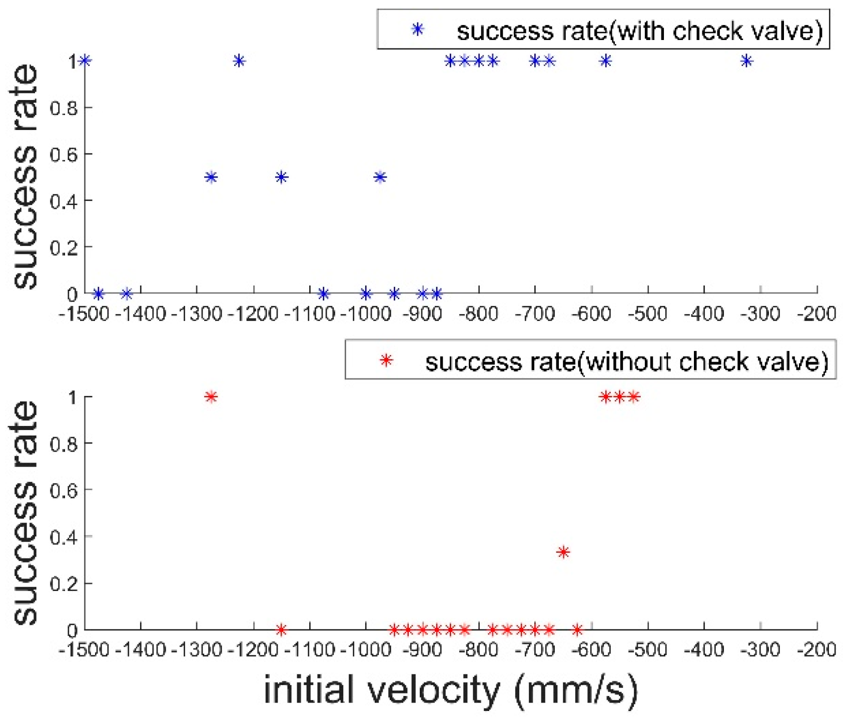
  • In order to solve the necessity of the suction cups vertically facing the wall during the approach-adsorption control, a low-cost wall-angle measurement was employed and fed forward the angle to the heading controller. The threshold range of the approach velocity was improved using a check valve.
We experimentally demonstrated the feasibility of the flying and adhesion robot based on approach and vacuum, the effectiveness of heading control which combined single-point laser and ultrasonics, and the enhancement of the check valves for adsorption-collision systems. Compared to other existing control methods, our method does not require additional sensors (e.g., force sensors, servo) and the modification of the controller is almost negligible.

1.4. Outline

This paper is organized as follows: In Section 2, we present the overall structural design and analyze the influence of structural parameters on the collision. The robot kinematics and dynamics modeling are carried out, including the adsorption model, contact model, and heading control model. In Section 3, we simulate the approach velocity and identify the system parameters. In Section 4, we verify our model by ground-collision experiments and flight experiments. Finally, we present conclusions and suggestions for future work.

2. Dynamics Model

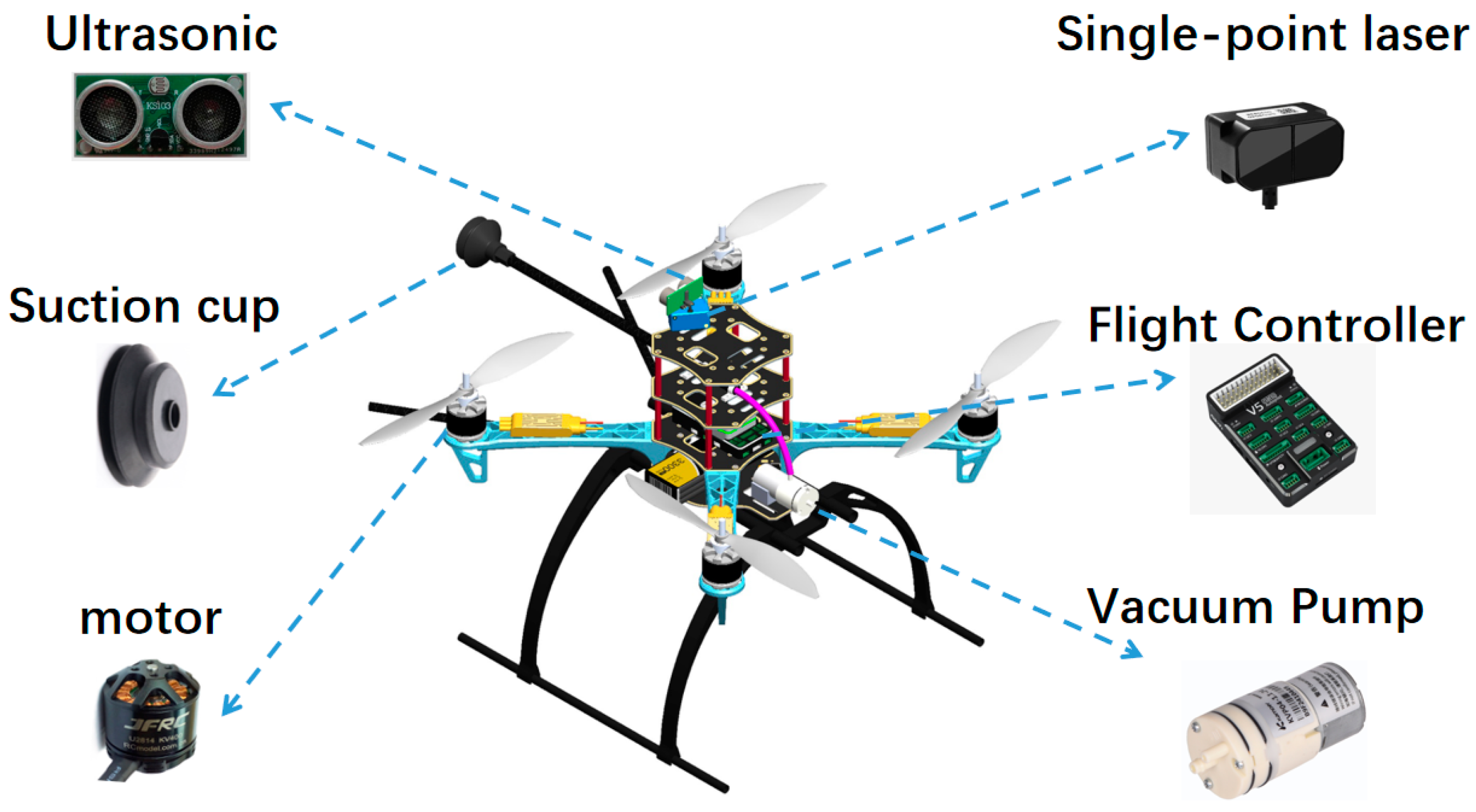
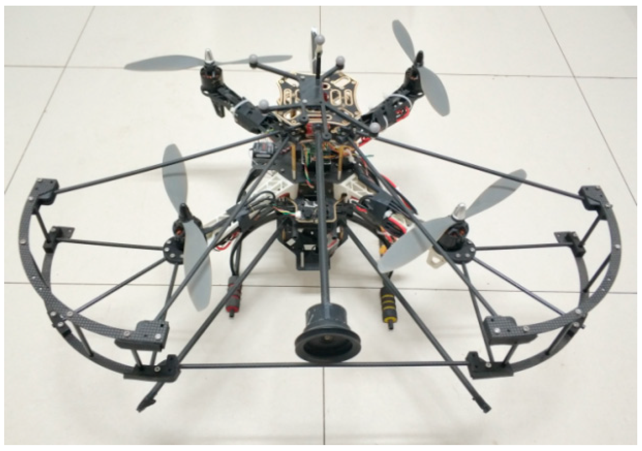
2.1. Overall Structural Design of the Flying and Adhesion Robot

As shown in Figure 1, the flying and adhesion robot mainly contains the flight controller, suction cup, laser module, ultrasonic module, vacuum pump, motors, support bar, propellers and other parts. Among them, the suction cup and vacuum pump constitute the vacuum negative-pressure module. The laser and ultrasonic modules constitute the approach-heading measurement system.
The flight-adsorption process is divided into three main phases: the free-space phase, the approach phase and the adsorption phase. The free-space phase includes taking off and hovering at the specified position. The approach phase mainly includes the robot adjusting its heading so that it faces the wall and flies towards it at the specified velocity. The adsorption phase includes the suction cups starting to make contact with the wall and completing the adsorption process under the combined effect of the vacuum pump and collision. If the suction cups do not successfully adsorb, the robot is controlled to disengage in the opposite direction.
The robot proposed in this paper uses an “X” frame, which allows the suction cups to be placed in the angle bisector of the two rotors. The distance from the suction cups to the center of the mass compared to the “+” frame is reduced. (In “+” frame, the x-axis in the body coordinate system points to one of the motors.)
As shown in Figure 2, the geometric center of four motors of the flying and adhesion robot is taken as the origin of the body coordinate system, and the direction of the angle bisector of the third and fourth motors is taken as the x-axis, the direction of the angle bisector of the second and third motors is taken as the y-axis, and the vertical direction is taken as the z-axis. d + l is the x-axis distance from the end of the suction cup to the center of the body coordinate system. l is the x-axis distance from the motor to the center of the mass. As shown in Figure 3, the height of the suction cup in the natural state is h 1 , and the height in compressed state is h 2 .

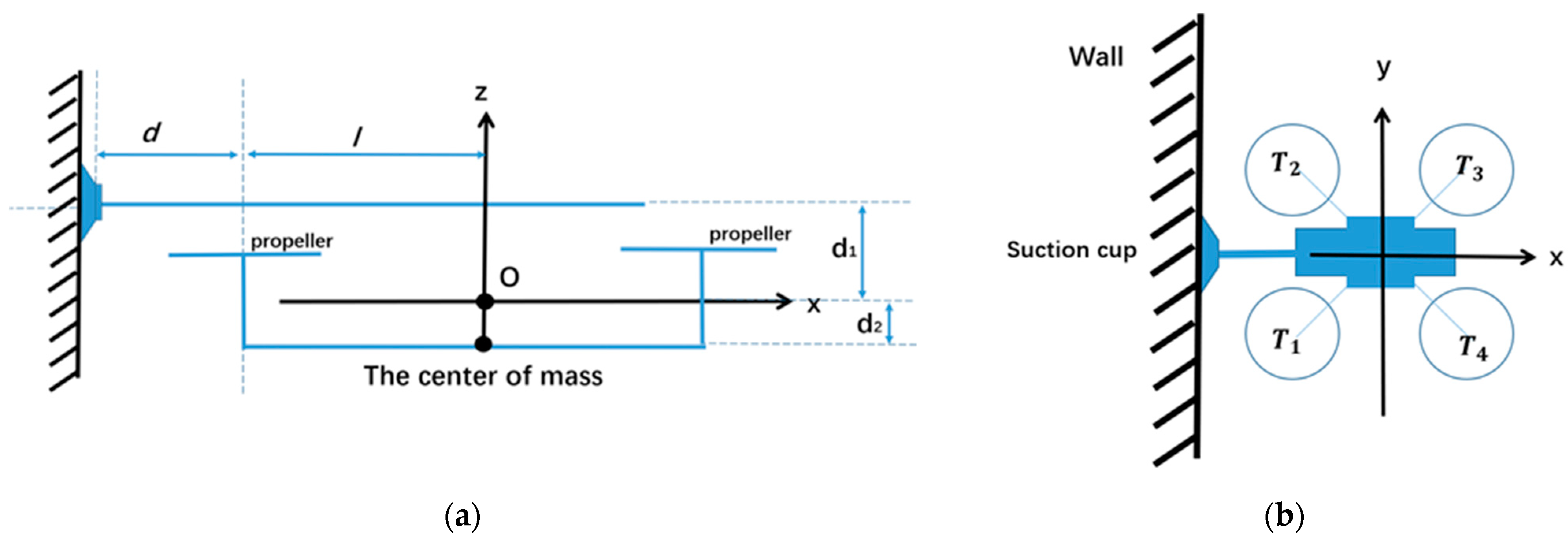
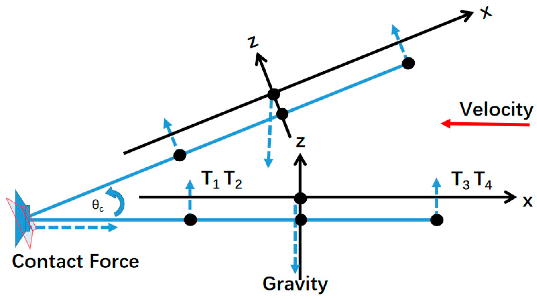
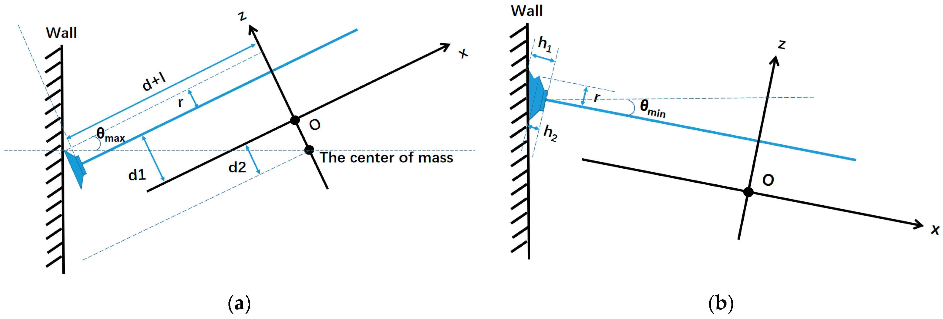
2.2. Modeling and Impact-Factor Analysis of Collision

The dynamics model of the flying and adhesion robot is shown in Equations (1)–(3) below, where T i is the lift force generated by the corresponding i motor, ω i is the propeller speed, and C T is the propeller lift coefficient. ρ is the air density. A is the rotor disk area. R is the radius of the propeller blade. m s p is the suction cup mass. m q u a d is the total mass of the robot except for the suction cups.
T i = C T ρ A ω i 2 R 2 = k f ω i 2
I ω = ω × I ω + M
where ω is the angular velocity, I is the rotational moment of inertia, and M = ( M 1 , M 2 , M 3 ) is the rotational torque. k f is the lift coefficient of the rotor. k m is the drag coefficient of the rotor. The thrust and moments can be given by the following equation.
[ F t o t M 1 M 2 M 3 ] = [ k f k f k f k f 0 k f l k f l k f l k f l d + l k f l k f l k f l k f l 0 k m k m k m k m 0 ] [ ω 1 2 ω 2 2 ω 3 2 ω 4 2 m s p g cos θ ]
The model of robot will change after the suction cups make contact with the wall and adsorb on the specified position. Assuming that the suction cups produce enough friction and adsorption force after contacting the wall with no relative displacement, its model will change from Equation (3) to the pendulum model as shown in Equation (4). There is a big difference between two models, and it is difficult for the controller to adapt to this change.
[ M 1 M 2 M 3 ] = [ k f d k f d k f ( d + 2 l ) k f ( d + 2 l ) d + l k f l k f l k f l k f l 0 k m k m k m k m 0 ] [ ω 1 2 ω 2 2 ω 3 2 ω 4 2 m q u a d g cos θ ]
The contact between the robot and the wall can be represented as three states, as shown in Figure 4a, which refers to a complete horizontal contact. Figure 4b refers to the case of small-angle contact, when both upper and lower edges of the suction cup can contact the wall and generate negative pressure. Figure 4c refers to the case of large-angle contact, when only the upper edge of the suction cup is in contact with the wall, and if the body is turned counterclockwise at this time, the sealing chamber cannot be established.
It should be noted that the flying and adhesion robot in Figure 4 adopts the method of placing the suction cup upwards, which can effectively improve the success rate. The method of placing downwards is analyzed as follows:
1 2 m v 0 2 = 1 2 m v 1 2 + 1 2 I x c ω c 2 = 1 6 m l 2 ω c 2
ω w a l l = ω c + T tot ( d + l ) m g ( d + l ) cos θ I x c dt
where v 0 is the velocity before contact, v 1 is the velocity after contact, I x c is the rotational inertia after contact, and ω c is the initial angular velocity after contact. The suction cups of the robot shown in Figure 5 are in the same plane as four arms.
After the robot makes contact with the wall, the body rotates under the effect of inertia because the center of mass is higher than the contact point and the contact velocity is not zero. Assuming that no displacement occurs at the collision point and the kinetic energy is conserved, the horizontal velocity of the body is transformed into the rotation with the suction cup as the center ω c .
By Equation (6), assuming that T tot = m g is constant for a short period (the rotor cannot change pitch and reversal; the rotational speed cannot change instantaneously), at this time with the θ increasing, the rotational moment becomes larger and the angular velocity increases further, and eventually overturns. In addition, the near-surface effect may occur in this process [19], resulting in an increase in rotor lift near the wall side, which exacerbates the overturning process. For these reasons, the horizontal-approach adsorption ( θ = 0 ) is used in this paper, and the suction cups are placed upward to avoid overturning due to the approach velocity.
In order to generate force when the robot contacts with the wall, it is necessary to adjust the attitude of the body. If the pitch angle is too large, it will easily cause the body to overturn and lead to adsorption failure, while too small an attitude angle is not able to generate a negative-pressure environment. Therefore, it is necessary to analyze the angle range at the time of contact, as shown in Figure 6. The position of the suction cup center point under the body coordinate system is ( d l , 0 , d 1 ) ; the position of the center of mass under the body coordinate system is ( 0 , 0 , d 2 ) , and the suction cup radius is r . Assuming that the approach velocity is approximately equal to 0, the maximum acceptable contact angle is shown in the following equation:
θ max = a r c t a n ( d 1 + d 2 + r d + l )
With the increase in d 1 , θ max shows a linear increasing relationship. Considering the effect of the collision on the structural strength of the body and the effect on the weight, the θ max of the robot used in this paper is about 15 degrees.
In order to maintain the perching state of the robot, it is necessary to set a support bar to prevent the torque caused by gravity after the motors stop rotating. According to the size of the suction cup, θ min can be obtained by the following formula:
θ min = a r c t a n ( h 1 h 2 2 r ) 6.05 °
According to θ min , the length of the adsorption-support bar can be determined. Once the angle is less than this value, the adsorption failure can be judged.

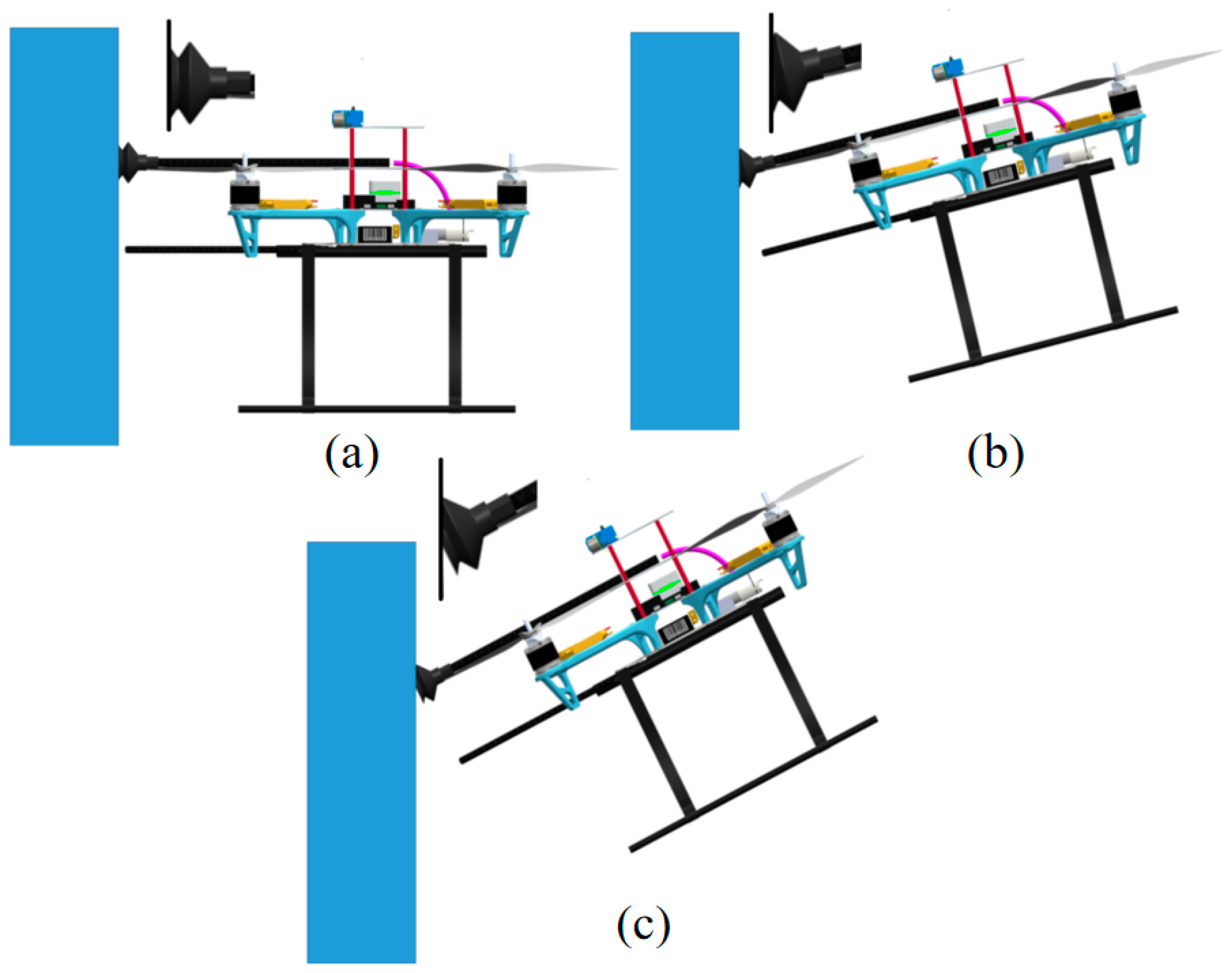
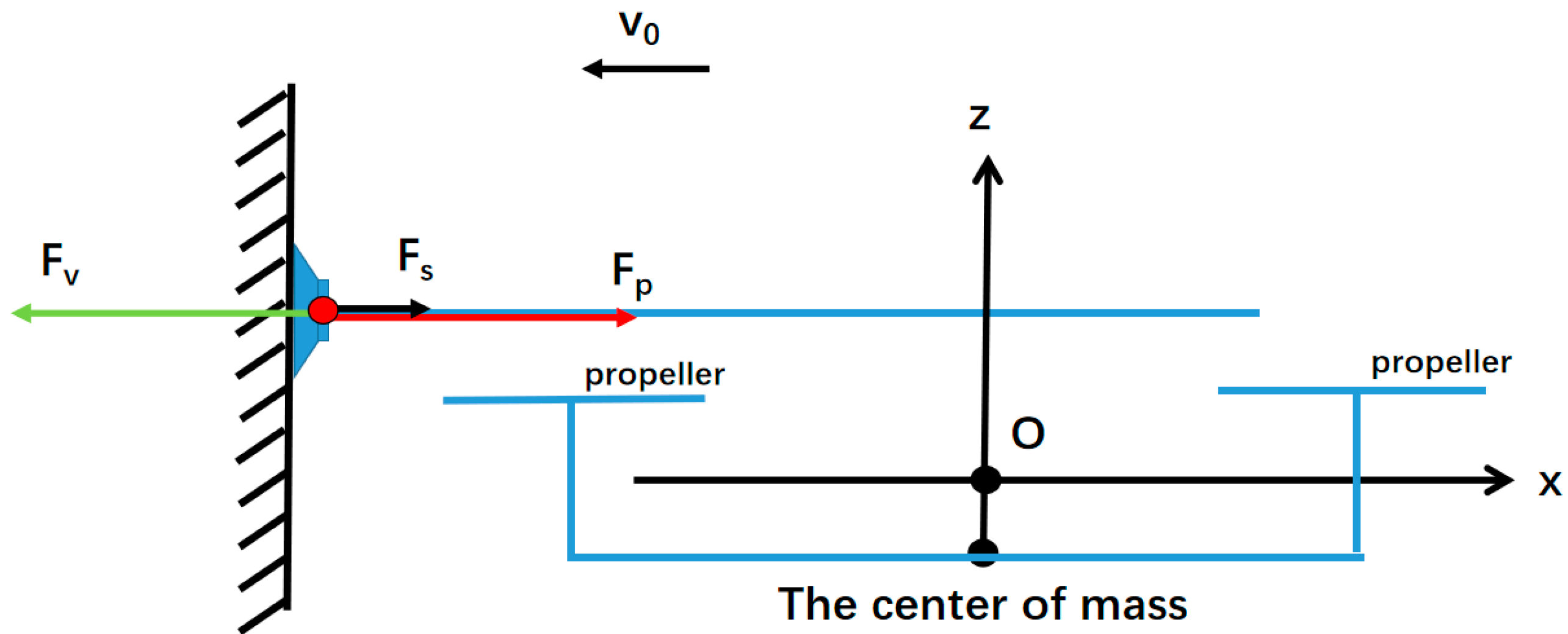
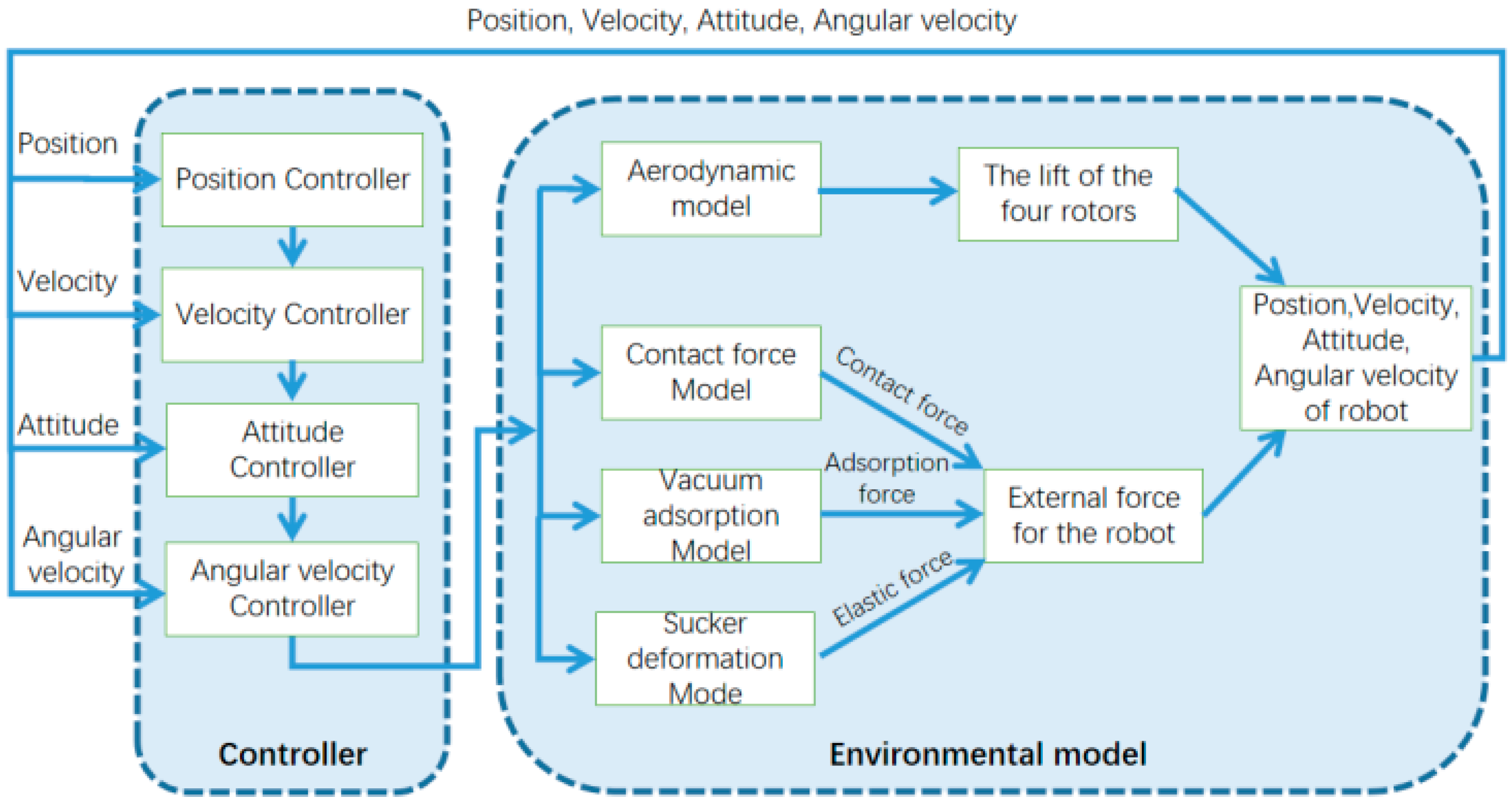
2.3. Approach-Process Modeling and Control

In this paper, the wall environment is treated as a rigid body and the robot is treated as a system with both elasticity and damping. Thus, the collision contact force can be equated to an elastic-damping model.
F p = { K | δ | n + D δ , w h e n   δ < 0 0 , w h e n   δ 0
δ = X p d l
where δ is the relative embedding between the robot and the wall, K is the contact stiffness, D = C | δ | n , and C is the damping coefficient. X p denotes the distance between the center of the robot and the wall. The effective working range of the suction cups is from h 2 to h 1 . If X p is from h 2 + d + l to h 1 + d + l , the suction cups can be in full contact with the wall surface to form a confined chamber.
As shown in Figure 7, the total force on the robot is
{ F = F p F v + F s F v = ( p 0 p ) A v F = ma
where p 0 is the atmospheric pressure, p is the air pressure of the suction cup, F s represents the elastic force due to the compression of the suction cup, as calibrated by Hooke’s law and experiments, and A v is the area of the suction cup.
F s = F max 1 k pos
In order to adapt to the wall environment with different materials, we use two layers of suction cups made of nitrile rubber. The radius of the suction cup is r . The suction cup is fixed directly on the carbon-fiber tube, and the other end of the carbon-fiber tube is connected to the vacuum pump through the silicone hose. These constitute our negative-pressure device. The inner diameter of the carbon fiber tube is r 1 , and the inner diameter of the silicone hose is r 2 . Ignore the skirt part when the suction cup is compressed, as well, the volume in the system is shown in the following equation.
V = π r 2 h + π r 1 2 l 1 + π r 2 2 l 2   h [ h 1 , h 2 ]
where l 1 is the length of the carbon-fiber tube and l 2 is the length of the silicone tube. According to the ideal gas-state equation:
P i n V = m R T M
Q = d ( P V ) d t = P i n d V d t + V d P i n d t = m R M d T d t
where V is the volume within the vacuum system and Q denotes the leakage rate within the system. The volume change includes the volume change of the vacuum-pump pumping and the volume change of the inner chamber of the suction cup, assuming that the temperature remains constant throughout the process. Therefore,
d P i n d t = p S e + Q V P i n d V V d t
According to paper [20], the expression for the leakage is Equation (17); however, it has too many factors and parameters such as the diameter of the leakage holes which are difficult to measure. According to the paper [21], the leakage curve of the painted wall can be obtained by fitting Equation (18), and the specific parameters are measured later in the calibration experiment.
Q = ( p r p c ) [ π d 4 p ¯ 128 η L + 1 6 ( 2 π R T M ) 0.5 d 3 L ( 1 + ( M R T ) 0.5 d p ¯ / δ 1 + 1.24 ( M R T ) 0.5 d p ¯ / η ) ]
Q = k 1 ( p 0 p ) k 2 ( p 0 p ) x = k ( Δ p ) n
Similarly, the flow-pressure curve of the vacuum pump can be measured by controlling the leakage rate.
S e = S max ( p 0 p ) S max p 0 p min
The whole vacuum system is composed of three parts: carbon-fiber tube, silicone tube and vacuum pump. The formula of total system flow conduction is shown as follows: C 1 is the carbon-fiber-tube flow conduction, C 2 is the silicone-tube flow conduction, and C 3 is the vacuum-pump flow conduction.
1 C = 1 C 1 + 1 C 2 + 1 C 3
C 1 = π d 1 4 128 η L p ¯
Based on the average pressure of the gas and the diameter of the pipe to determine whether it is a molecular or viscous flow, we believe that it is a viscous flow in our vacuum system. According to the piping parameters calculation, C 2 is in 165.8890 L/min to 331.7779 L/min. C 1 > C 2 > > C 3 , so C 1 and C 2 can be neglected. C C 3 = S e .
Based on the contact and negative-pressure models, the approach velocity of the flight adsorption robot should satisfy the following performance function (22). The specific control method is not the focus of this paper. Even if the traditional control method, such as PID controller, is adopted, the success rate of flying adsorption can be guaranteed when the parameters change.
v min and v max denote the minimum and maximum approach velocity that can be successfully adsorbed. α safe denotes the approach velocity coefficient and β impact denotes the impact coefficient of the collision force on the body.
{ a r g m a x G ( v ) v = α safe [ ReLU ( v v min ) + ReLU ( v max v ) + c ] + β impact F ( v ) F ( v ) = max ( F p ) s t . v min < v < v max     F ( v ) < F max
The traditional wall-azimuth measurement method uses LIDAR to acquire the whole plane data to calculate the desired heading angle. Instead, we use a single-point laser sensor and an ultrasonic sensor. The large scattering angle of the ultrasonic sensor is used to calculate the vertical distance of the robot relative to the wall surface. Compared with the traditional LIDAR solution, the weight and cost of single-point laser plus ultrasonic are much smaller than that of single-line LIDAR.
As shown in Figure 8, since the range of ultrasonic sensor is about 60–70 degrees, the vertical distance to the wall d s o n a r can be obtained and the length d l a s e r can be obtained using the laser sensor.
ψ d e s i r e d = ψ + arccos ( d s o n a r d l a s e r ) b i a s ψ

3. Simulation

In the simulations, we first perform parameter identification and simulation verification of the adsorption process of the robot on the basis of specific parameters.

3.1. Determining the Elasticity Coefficient of the Suction Cup

The elastic-force model of the suction cups was fitted by using different weights placed on the suction cups and measuring the deformation of the suction cups using vernier calipers. By linear fitting through Matlab, we can obtain the relationship between the elastic force and compression of 60 mm double-layer NBR suction cup, as shown in Equation (24). The simulation of the finite-element statistics of the suction cup is also carried out by using ANSYS. The simulation results show that the equation we fitted by experiments and the simulation results have good consistency.
F s = ( 171.50 8.528 × ( 13.19 + p o s × 1000 ) )

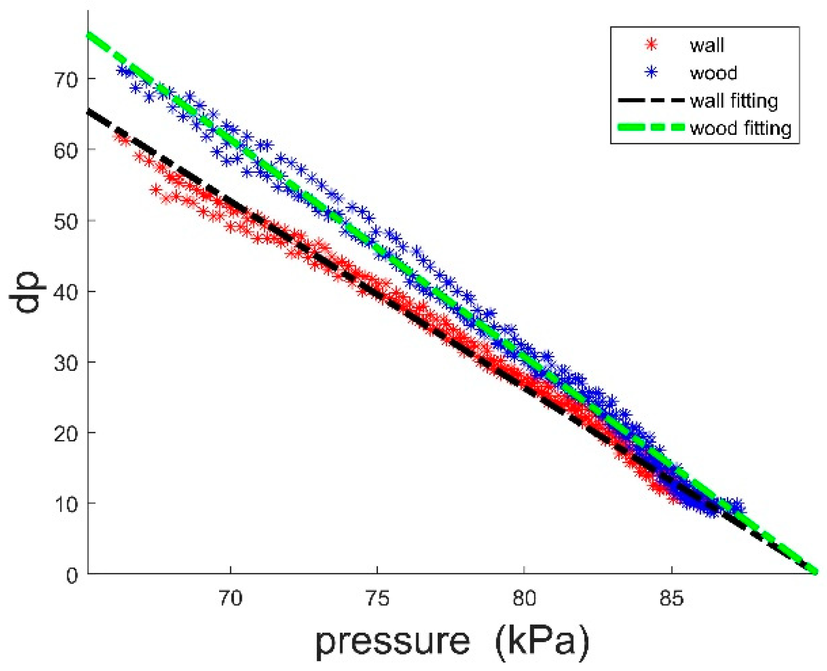
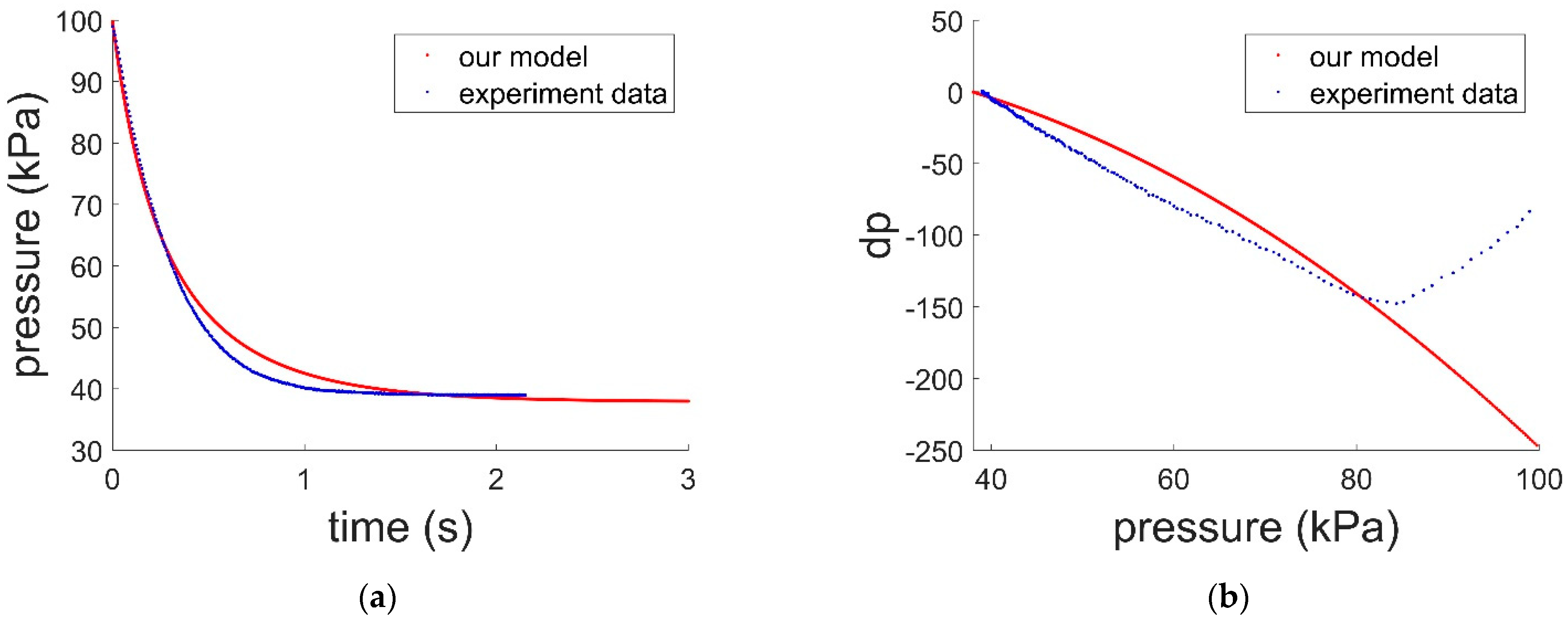
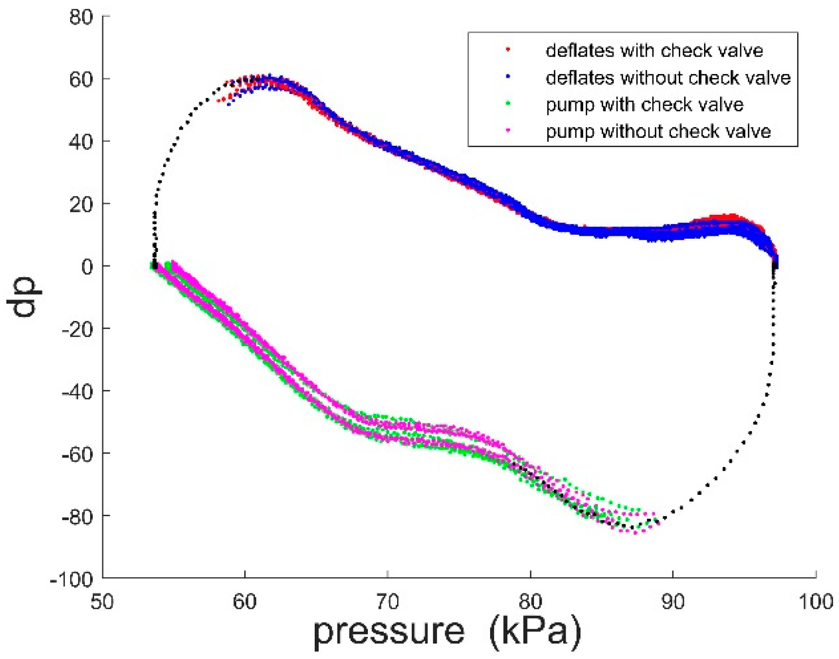
3.2. Determining the Leakage Rate of the Suction Cup

Since there are too many factors affecting the leakage rate of suction cups in different materials, the leakage rate of suction cups needs to be measured.
In order to obtain the relevant leakage-rate parameters, we conducted a leakage rate experiment on a painted wall using a 60 mm suction cup. We aspirated the suction cup through a vacuum pump and then applied a certain force to the suction cup. The force applied in this experiment was the previously calibrated maximum pressure for the deformation of the suction cup. This limits the deformation of the suction cups after the pump stops working. Then the vacuum pump is turned off and the curve of air pressure variation inside the suction cup was obtained.
By differentiating the pressure and establishing the relationship between the rate of change of air pressure and air pressure. It can be seen that the rate of air-pressure change is linearly related to the air pressure. The air-pressure leakage rate of different materials on the surface has a large difference.
As shown in Figure 9, the leakage rate of the painted wall can be obtained by fitting.
Q = 1 . 372 ( Δ p ) 1 . 105

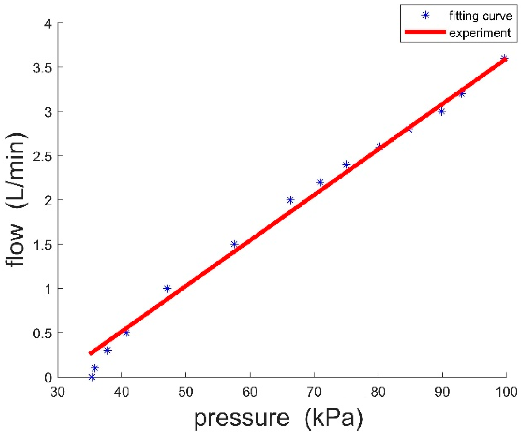
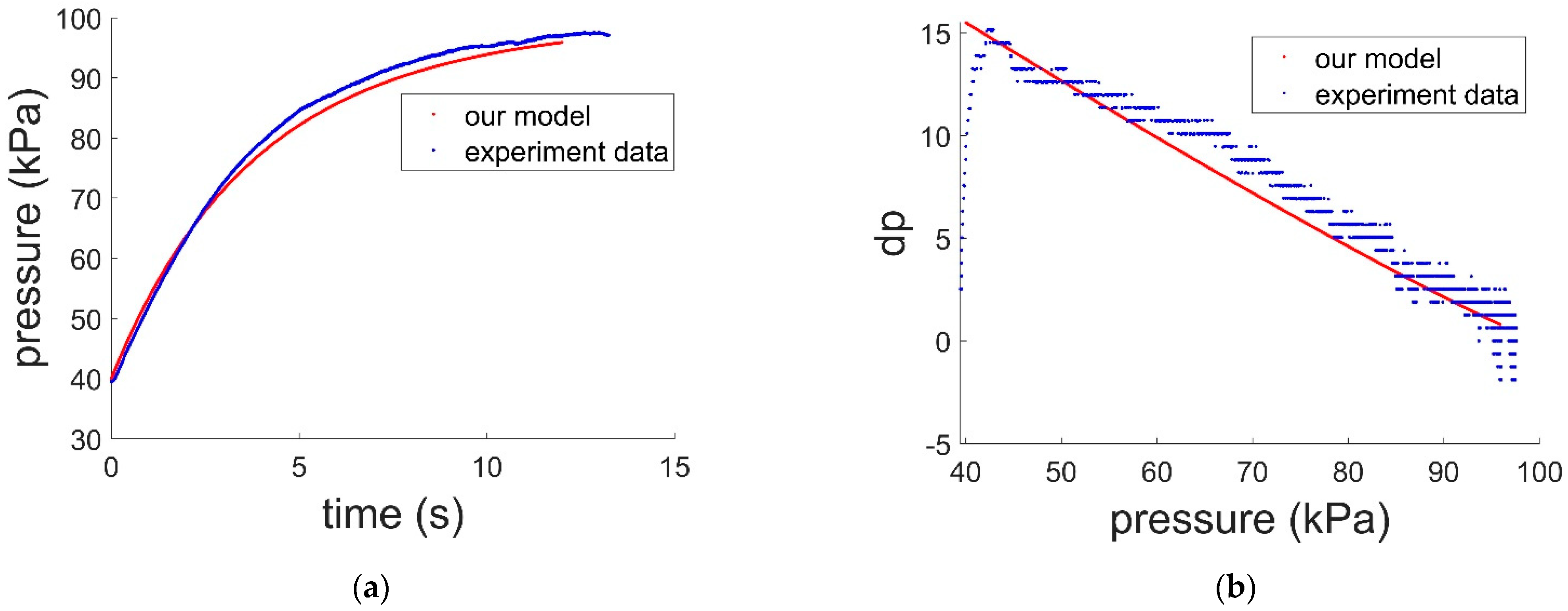
3.3. Determining the Curve between Air Pressure and Flow

In order to determine the working characteristics of the vacuum pump, we need to measure its flow curve under different air-pressure conditions and fit the equation. We measure the flow under different air pressures by adjusting the flow meter and throttle valve. As shown in Figure 10, it can be obtained by fitting.
S e = 3.6 ( p 0 p ) 3.6 × 70 ( L / min )

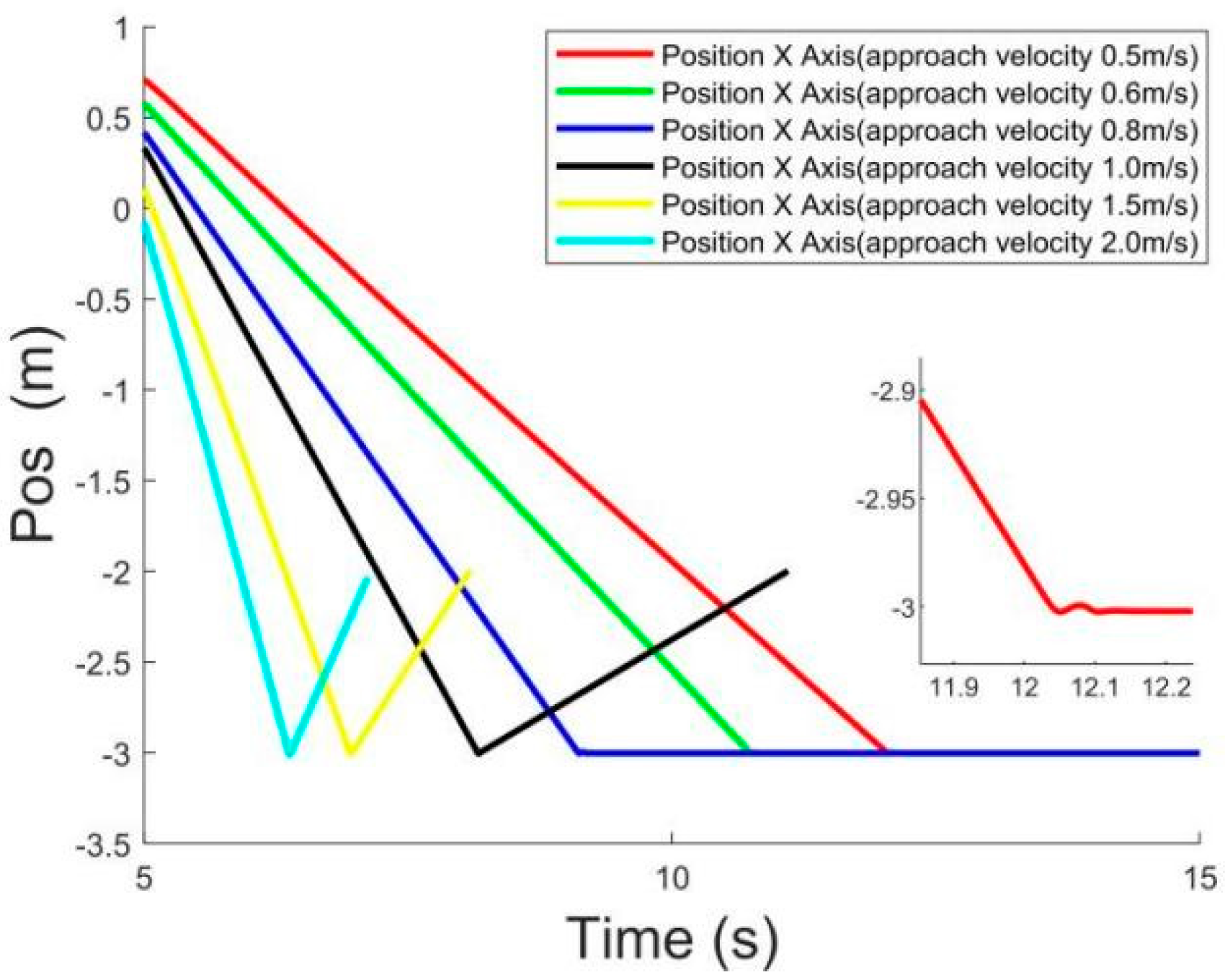
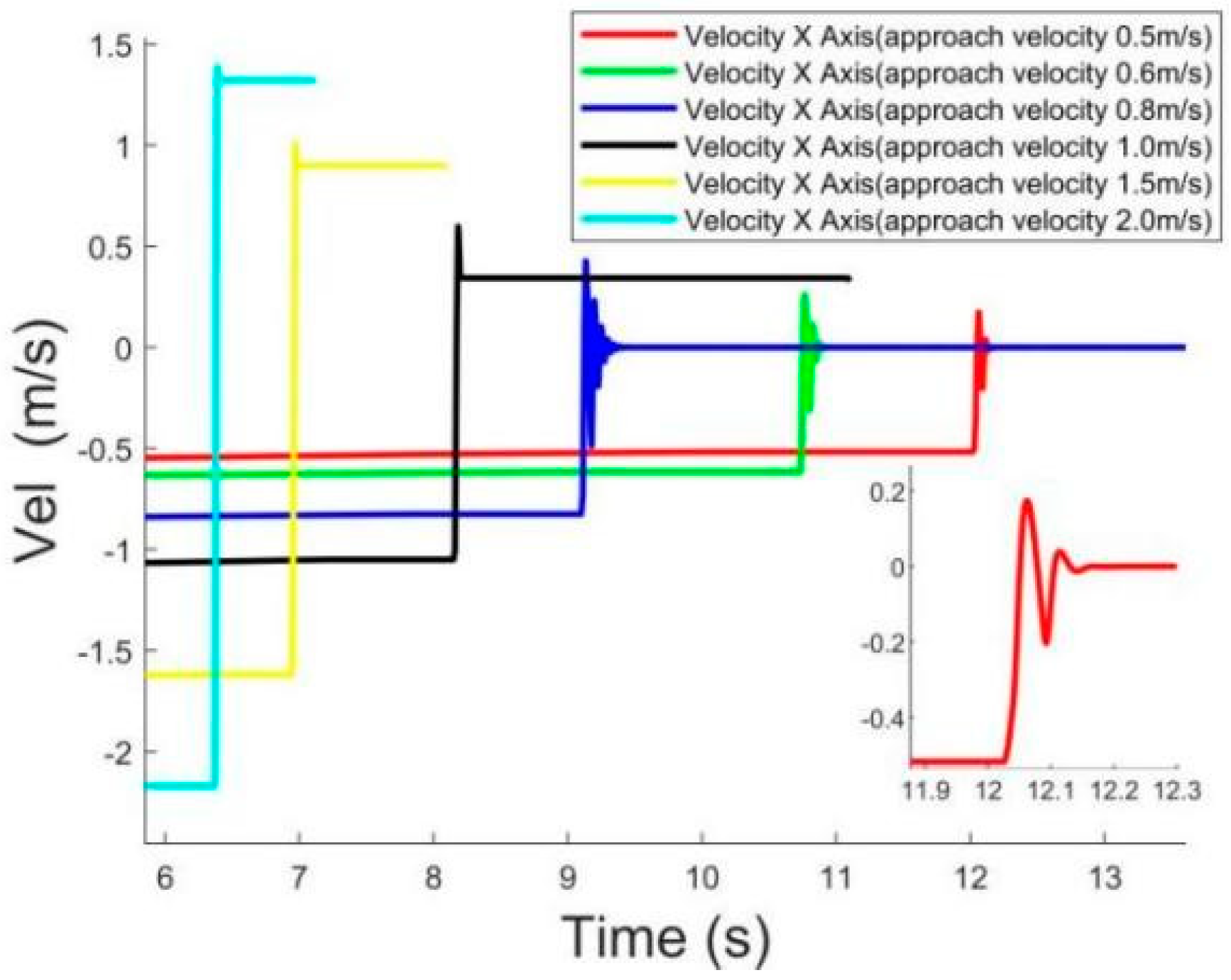
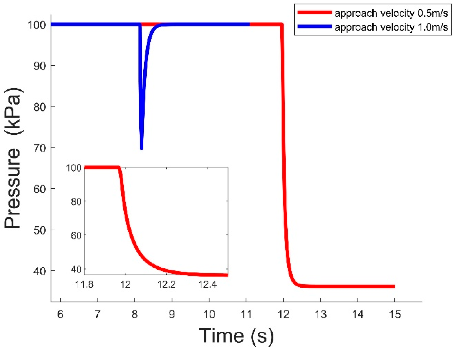
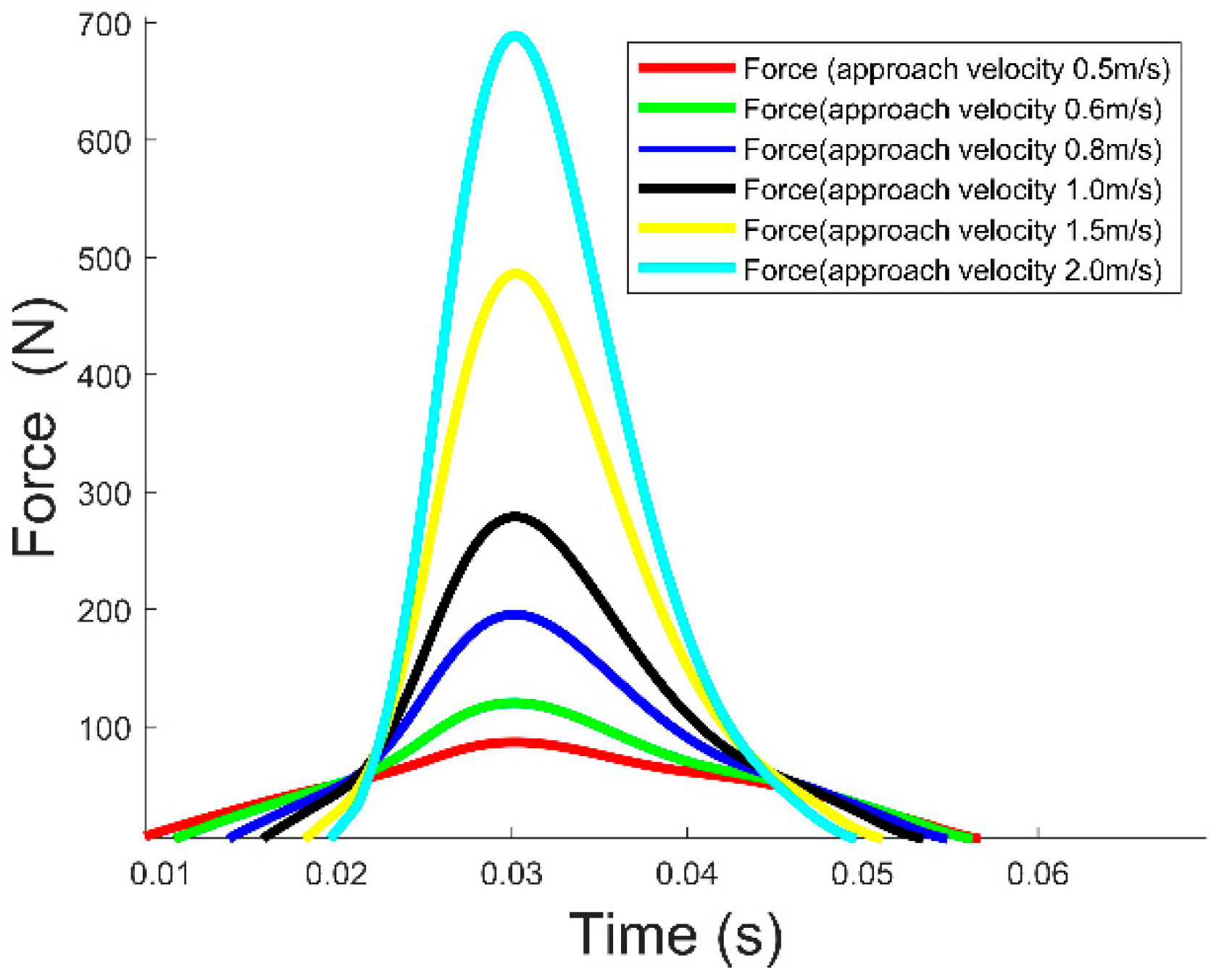
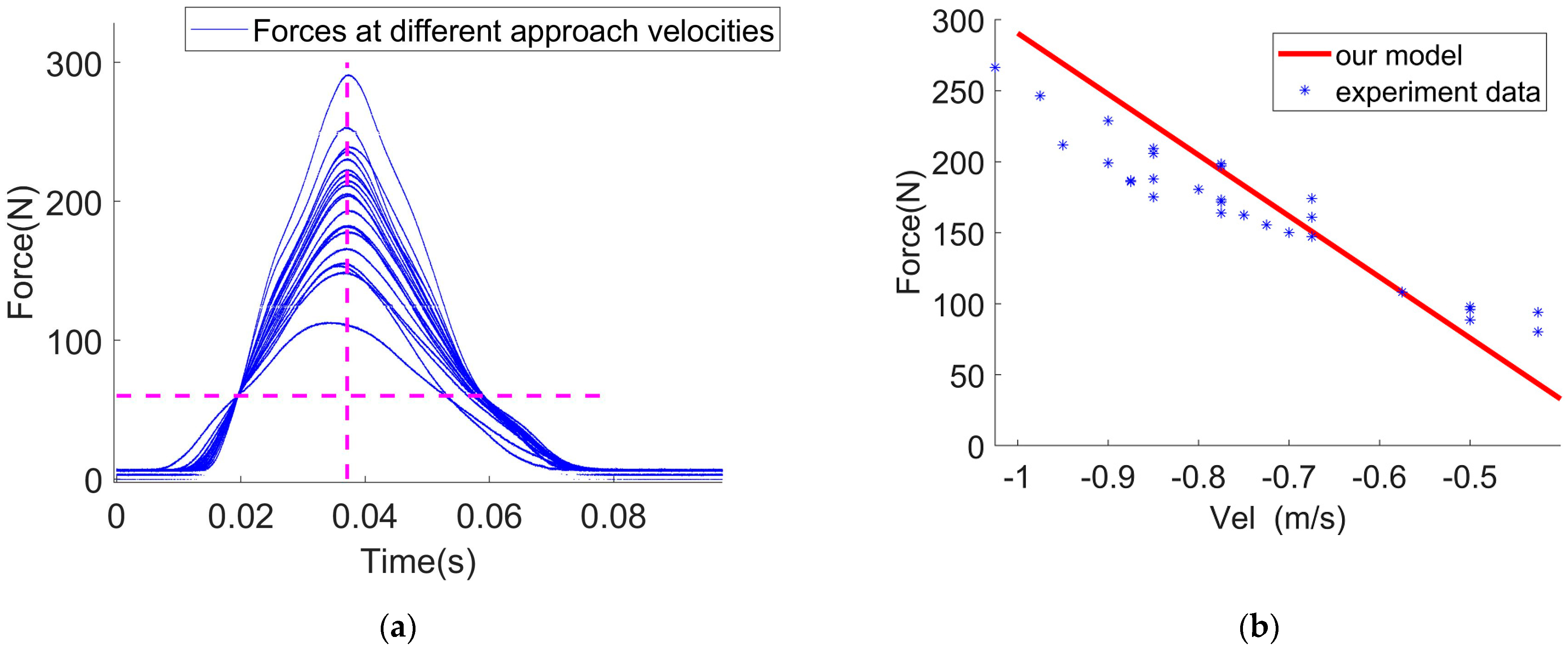
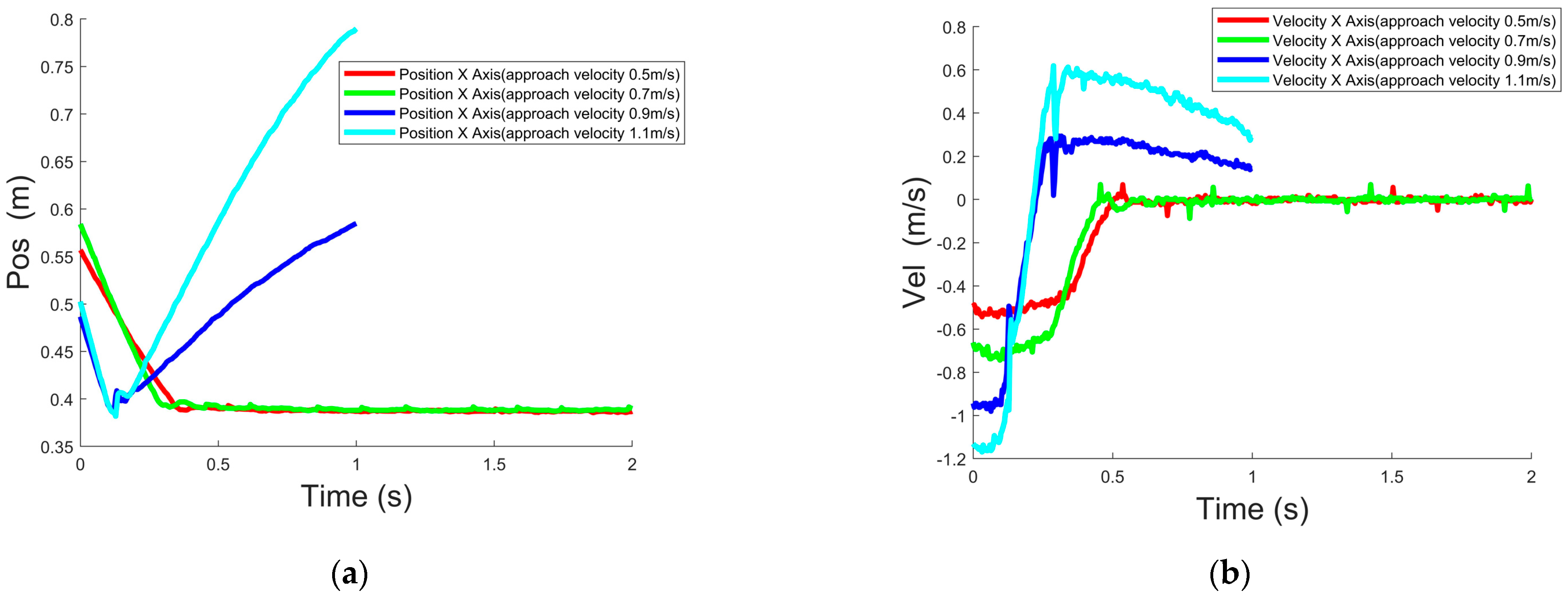
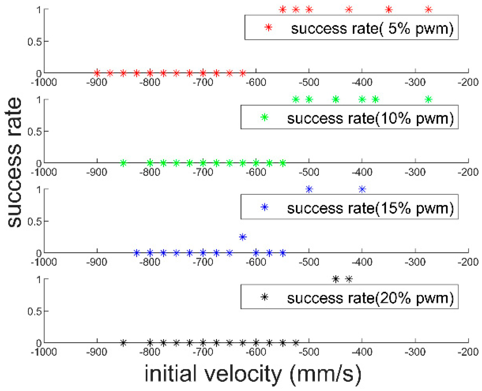
3.4. Simulation of Collision Flight-Adsorption System under Matlab at Different Velocity

Combining the obtained parameters with the established adsorption model, we have validated our model by Simulink. The system control structure of the simulation is shown in the following block diagram (Figure 11).
By giving the desired spatial position point, the robot is guided to take off from the starting point to the specified position and hover, adjust the heading, and send the approach velocity command for approach adsorption.
As shown in Figure 12, the robot takes off and then adjusts the heading angle within 2 s to 4 s based on the feedback ultrasonic and single-point-laser distance data. The desired yaw angle is calculated by Equation (23).
After 5 s, the flying and adhesion robot is given a desired x-direction desired velocity for approach adsorption, and the vacuum pump is turned on to generate negative pressure within the suction cup after contacting with the wall. The position, velocity, and contact force are simulated during this process. As shown in Figure 13, Figure 14 and Figure 15, the curves of position, velocity, collision force with time after the horizontal collision between the robot and the painted wall from the initial approach have a velocity of 0.5 m/s to 2 m/s. The simulation terminates after the robot moves to 1m from the wall (position x = −2 m).
From Figure 13 and Figure 14, we can see that the robot will successfully complete the adsorption process when the approach velocities are 0.5 m/s, 0.6 m/s and 0.8 m/s, and the final speed reaches 0 m/s. When the robot’s approach velocity is greater than or equal to 1.0 m/s, the robot will directly bounce off the wall. If the robot successfully finishes the adsorption process, the speed and position will be a little jittered.
As can be seen in Figure 15, at this approach velocity, the suction cups are in contact with the painted walls to establish a negative-pressure adsorption environment. With the negative-pressure adsorption force, two situations exist for the flying and adhesion robot: (a) as shown in the blue line above, the robot bounces off the wall because the vacuum pump cannot establish a negative-pressure adsorption environment in a limited time, reducing the bounce velocity to 0 m/s; (b) as shown in the red line above, the vacuum pump can generate enough adsorption force in a limited time to counteract the force of the wall for the flying and adhesion robot. Eventually the robot stops at the wall position, the velocity decreases to 0 m/s and the air pressure decreases and stabilizes at 36.2 kPa.
By giving different approach velocities without the vacuum pump, the robot generates different collision forces. As can be seen in Figure 16, the greater the approach velocity is, the greater the resulting collision force is.

4. Experiment

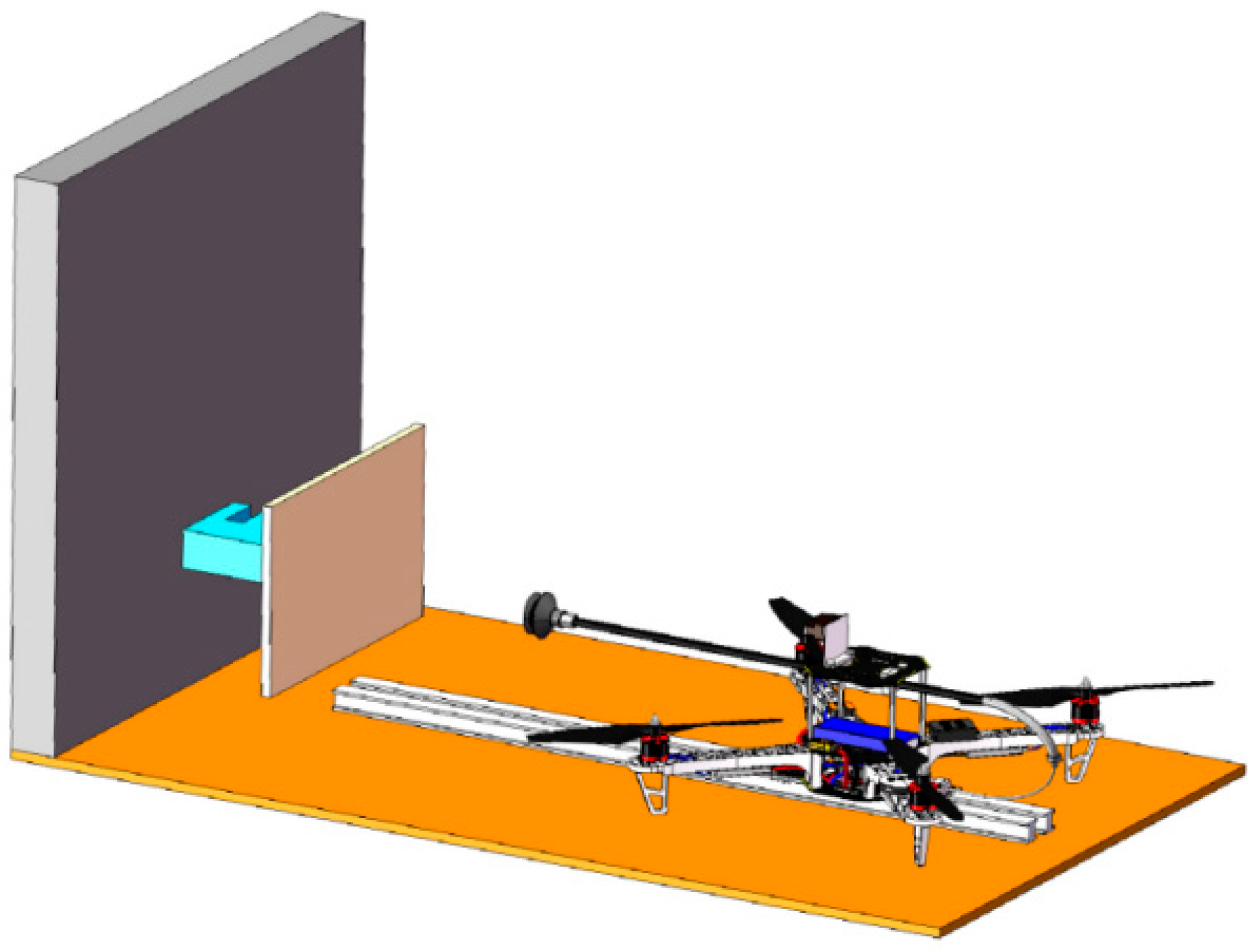
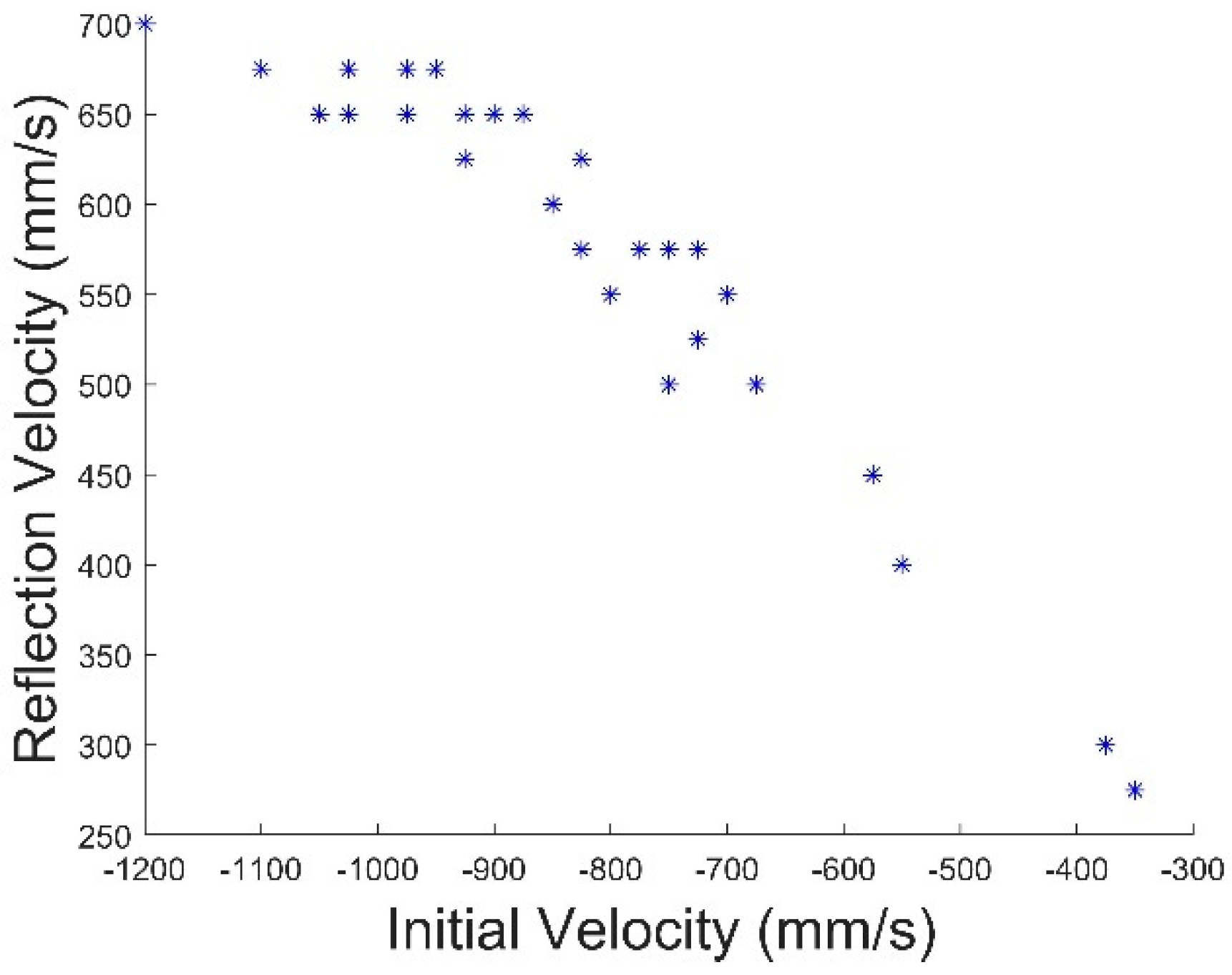
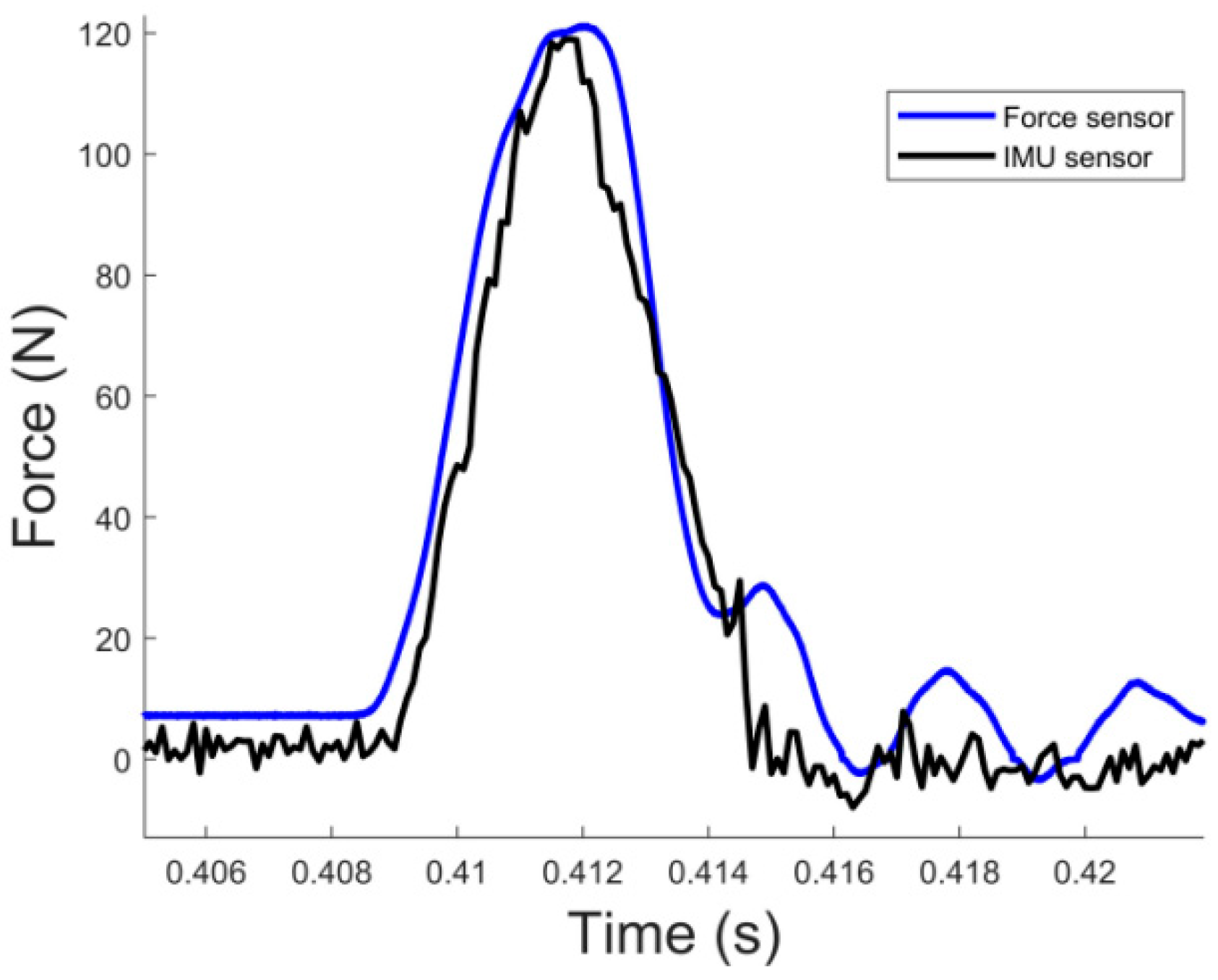
4.1. Rail Experiment

As the actual flight-approach process, the robot’s attitude, velocity, heading and other factors have an impact on the final contact results. Therefore, we built a slide-rail experimental platform for approach experiments, using the same configuration as the robot (including suction cup, vacuum pump battery, etc.) to simulate the mass distribution, and using the slide rail to conduct approach experiments on the surface of painted walls to obtain relevant experimental parameters and verify the results of the simulation.
As shown in Figure 17, the robot was mounted on an aluminum plate using two parallel slide rails, and the distance between the robot and the wall was measured by Benewake’s TFmini Plus (Beijing, China). A single-point laser sensor working at 250 Hz was used to calculate the velocity before the collision and the bounce velocity using the recorded data. In addition, the contact force was measured using an S-type force sensor during the approach process. The experimental bench top was simulated using a wooden board and a painted wall putty for the painted wall. At the same time, an Xsens IMU (Enschede, Netherlands) sensor was added to detect the acceleration from the contact at 400 Hz to indirectly verify the collision contact force and provided a source of data for the robot’s contact detection.
As shown in Figure 18, there is the curve between collision velocity and reflection velocity for a single suction cup in the contact collision. It can be seen that the ratio of incident velocity to reflect velocity is about 0.7, and the law is relatively linear. We use experiment data to identify system parameters in Equation (9).
The acceleration generated by contact with the wall is measured by comparing the acceleration returned by the S-type force sensor with that of the Xsens accelerometer placed on the rail slider (Figure 19). Therefore, the acceleration sensor can be used for contact detection.
We validated the two-stage collision model by multiple collision experiments. As can be seen in Figure 20a, we adjusted the peak of the collision force to the same time. At this point, the collision-force curves intersect at a point roughly 60 N, which is the peak of the suction-cup elastic force we measured. The relationship between the peak contact force and the approach velocity is shown in Figure 20b. It can be seen that our model in the simulation is consistent with the experiment.
As in Figure 21 and Figure 22, the adsorption and leakage experiments with the actual suction cup and vacuum pump show that the model curve and the actual experimental curve are consistent. The left side shows the change curve of air pressure in the suction cup with time, and the right side shows the change curve of the air-pressure change rate with air pressure. It verifies the correctness of our model of the vacuum pump and air pressure leakage inside the suction cup.
The position and velocity curves in the slide-rail experiment are shown in Figure 23. Because of the existence of friction in the rail, the velocity decays slowly before and after the contact. We used 0.5 m/s, 0.7 m/s, 0.9 m/s and 1.1 m/s for approach adsorption, respectively, where the adsorptions of 0.5 m/s and 0.7 m/s succeed and the adsorptions of 0.9 m/s and 1.1 m/s fail. The curves are roughly consistent with those in the simulation.
We conducted collision-adsorption experiments by adjusting the duty cycle of the vacuum pump. The flow rate of the vacuum pump under different duty cycles was not consistent. The lower the duty cycle was, the higher the pumping speed of the vacuum pump was. As can be seen in Figure 24, the lower the flow rate is, the smaller the dividing line of approach velocity between successful and failed adsorption is.
In addition, because of the approach velocity in the collision process, the suction cup will produce a large deformation in a short time. The gas in the suction cup and pipe is compressed rapidly beyond what the vacuum pump can accept, so a certain range of overpressure will be generated in a short period of time. This part of the overpressure will increase the efficiency of the vacuum pump on the one hand, but on the other hand, it will produce a reverse force on the robot through the suction cup, causing the suction cup to disengage. Therefore, a check valve (shown in Figure 25) was connected through a three-way pipe to discharge this gas in case of overpressure.
We tested the effect of the check valve on the adsorption vacuum on the painted wall, and it can be seen in Figure 26 that the suction and leakage-rate curves of the suction cup basically overlap, so the check valve has basically no effect on the change in air pressure inside the suction cup. The check valve is closed during the whole process, and the check valve has a good seal and does not produce additional leaks.
As shown in Figure 27, the effect of the check valve on the approach velocity is tested at different velocities in the ground-collision experiment. It can be seen that using the check valve can increase the maximum value of the approach velocity from 600 mm/s to 850 mm/s. In the presence of a check valve, when overpressure is generated in the case of high approach velocity, the gas inside can be discharged quickly, which is conducive to the establishment of a negative-pressure environment, but the success rate cannot be guaranteed.

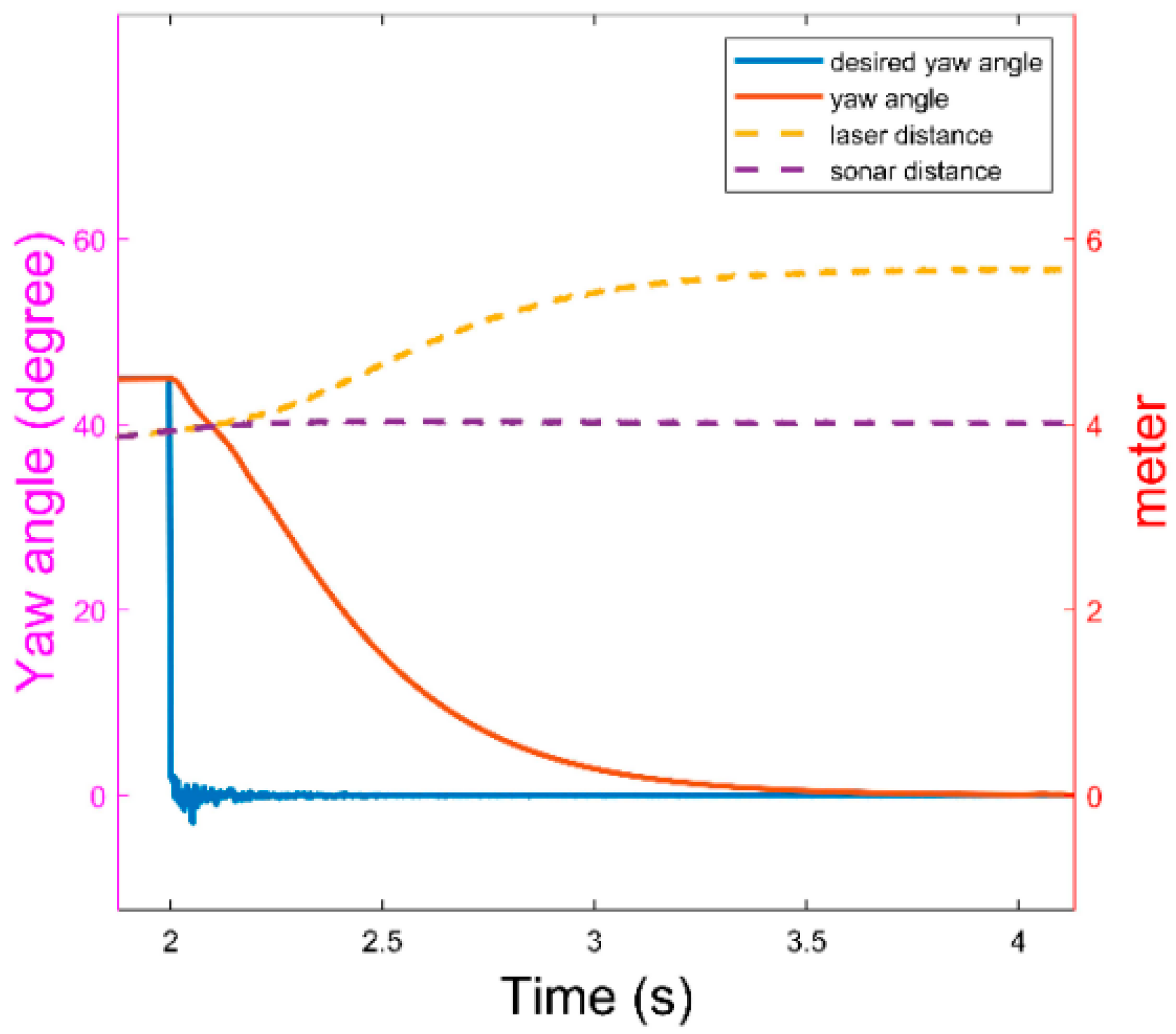
4.2. Heading-Control Experiment

From Table 1, it can be seen that by our single-point laser combined with ultrasonic measurement, we can obtain a good measurement of the plane with an error of less than 3 degrees from the angle obtained through the motion-capture system.

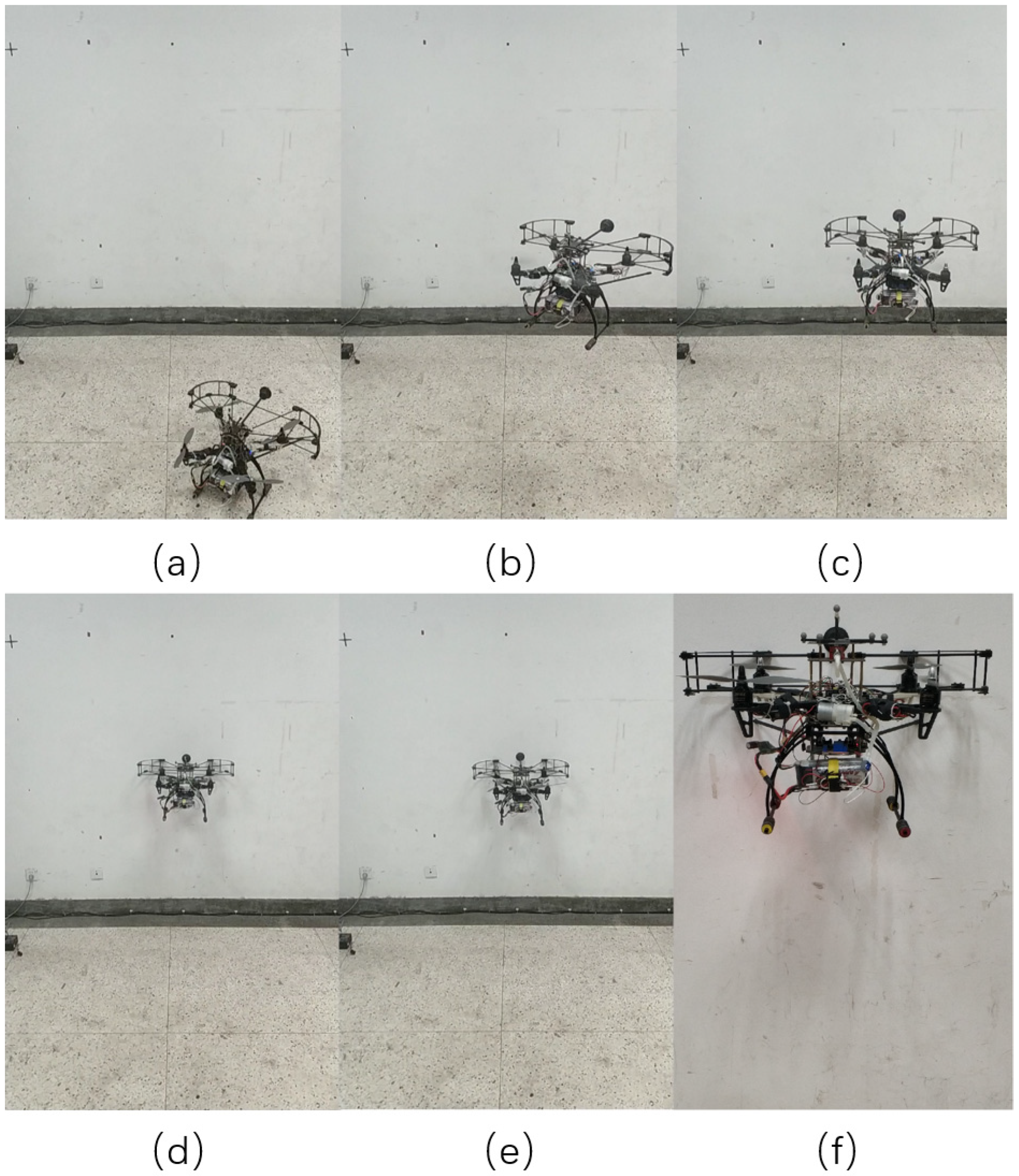
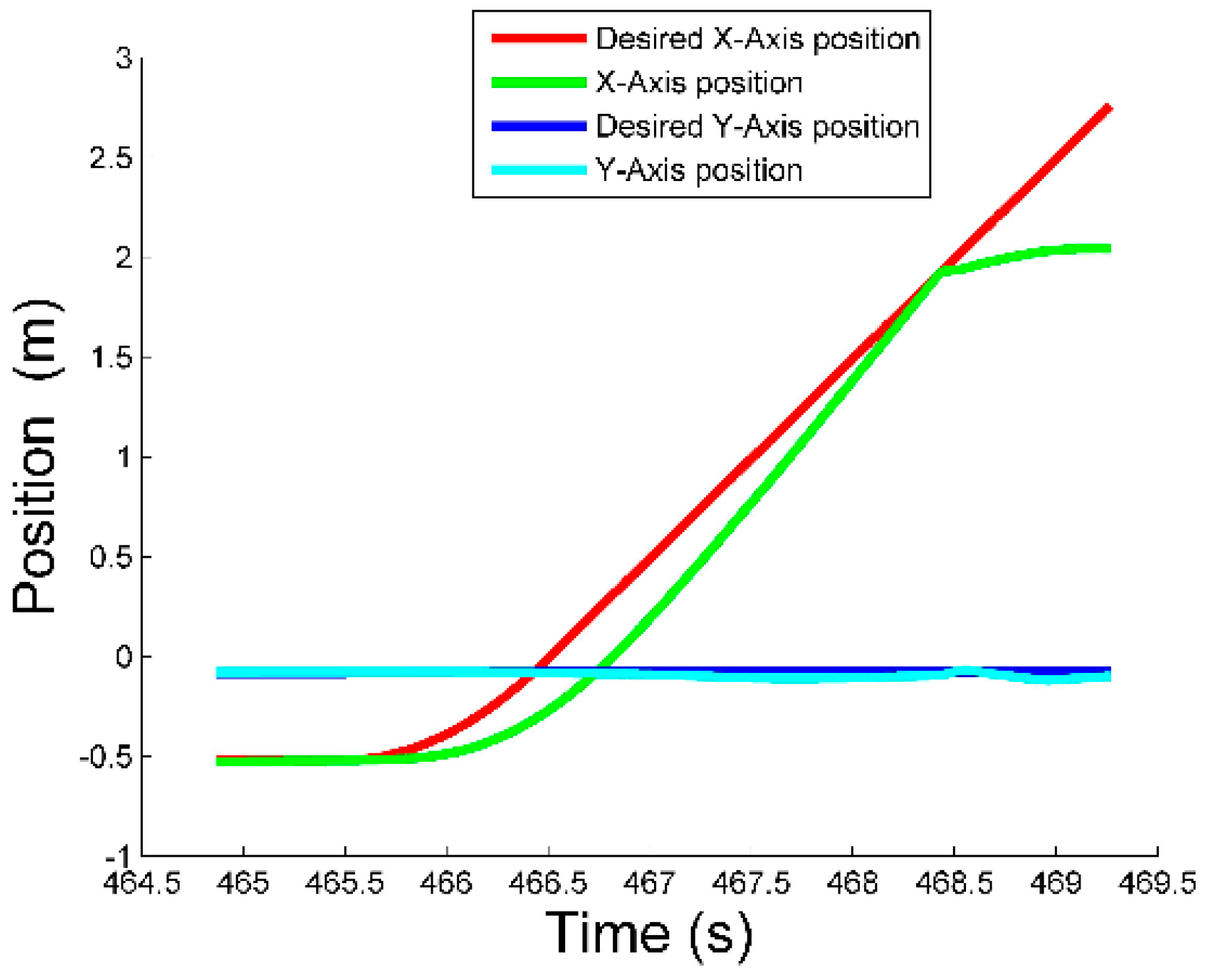
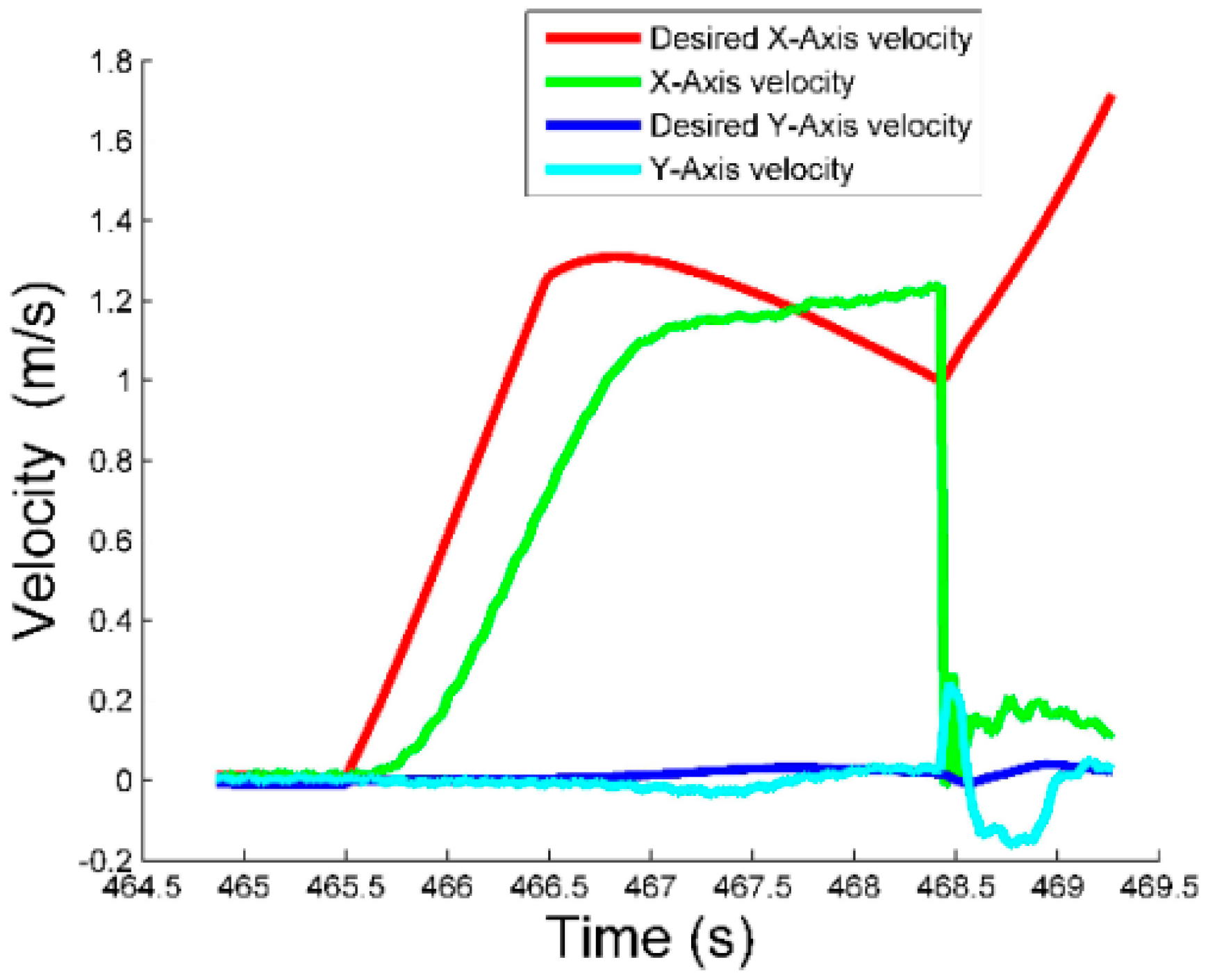
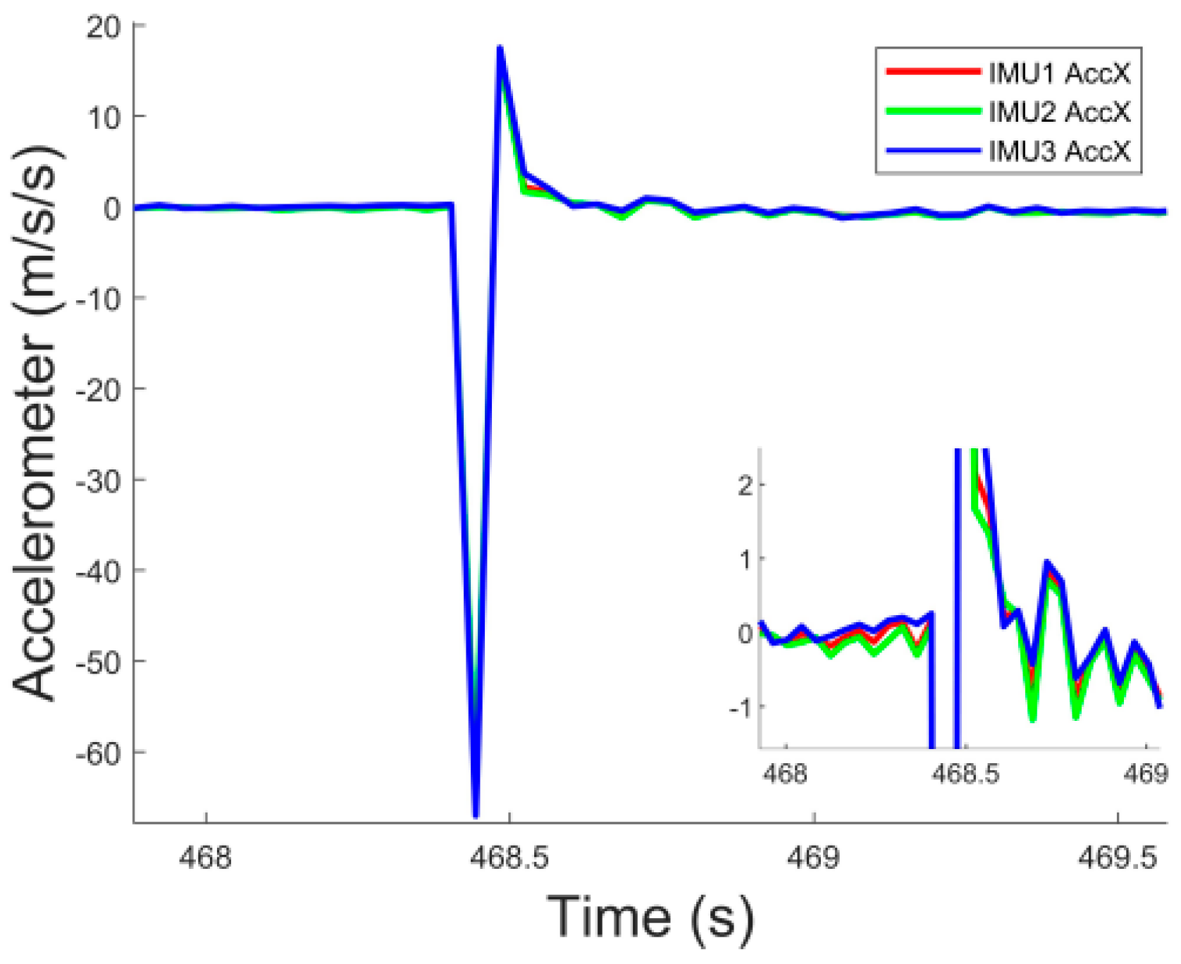
4.3. Actual Flight Experiment

We built the experimental test platform based on the F450 frame. As shown in Figure 28, we used 60 mm-diameter suction cups, carbon-fiber tubes and carbon-fiber plates to build the protection and support stand. The APC1047 propellers and U2814 motors were used as the power system. The vacuum pump with a maximum flow rate of 3.6 L was used as the negative pressure source. The effect of collision adsorption was tested in an indoor Optitrack (Corvallis, OR, United States) motion capture environment, and the experimental results show that our robot can successfully adsorb under approach adsorption. In addition, at excessive collision velocity, the robot was able to detect whether the collision was successful and execute the adsorption failure strategy.
Figure 29 illustrates the complete adsorption process of the flying and adhesion robot. Figure 29a: The robot takes off on the ground; Figure 29b: The robot flies to a specified position and starts to adjust the heading angle to face the wall; Figure 29c: The robot flies towards the wall at a specified approach velocity; Figure 29d: The robot makes contact with the wall and the vacuum pump works; Figure 29e: The rotors stop working and the robot completes the adsorption process; Figure 29f is a magnified view of the robot perching on the wall.
As shown in Figure 30 and Figure 31, the robot took off from position (−0.5, 0), moved toward the target point with a target velocity of 1.2 m/s, and finally stopped at position (2, 0) by approach adsorption. At this point, the velocity jumped to 0 m/s, producing an acceleration greater than 60 m/s2, as shown in Figure 32.
If the pressure inside the suction cup does not decrease after the contact between the suction cup and the wall, the robot detects that the adsorption process has failed and sends the desired velocity −2 m/s to disengage from the wall and prevents the robot from overturning.

5. Conclusions

This paper presents a detailed analysis of the traditional flying and adhesion robot that is prone to overturning during the collision and has a low success rate; establishes a model of the adsorption process; analyzes the factors of the model parameters on flight adsorption; and optimizes the body structure. An initial solution framework is provided for the collision-adsorption process of the flying and adhesion robot under different parameters. The robot is able to obtain a more suitable collision velocity and ensure the success rate of collision adsorption in this way. In addition, the body structure and adsorption device can be optimized to further improve the adsorption success rate of the flying and adhesion robot. The simulation and experiment results validate our method. The check valve can increase the maximum value of an approach velocity from 600 mm/s to 850 mm/s, expanding the approach velocity range of robot. For our flying and adhesion robot, an approach velocity of less than 800 mm/s always ensures that the robot has good performance to adsorb to the painted wall. In the future, we will obtain the adsorption velocity by visual detection and reinforcement learning.

Author Contributions

Conceptualization, C.H. and Y.L.; methodology, C.H.; validation, C.H., Y.L. and K.W.; formal analysis, C.H.; investigation, C.H.; writing—original draft preparation, C.H.; writing—review and editing, B.B., K.W. and Y.L.; visualization, B.B.; supervision, Y.L.; project administration, Y.L.; funding acquisition, Y.L. All authors have read and agreed to the published version of the manuscript.

Funding

Research supported in part by China National Science Foundation under grants 61473155, by Sharing Technology Project 41412040102, by Jiangsu Technology Department under Modern Agriculture BE2017301, and by Six talent peaks project in Jiangsu Province GDZB-039.

Institutional Review Board Statement

Not applicable.

Informed Consent Statement

Not applicable.

Data Availability Statement

Not applicable.

Conflicts of Interest

The authors declare no conflict of interest.

References

  1. Liu, Y.; Chen, H.; Tang, Z.; Sun, G. A bat-like switched flying and adhesive robot. In Proceedings of the 2012 IEEE International Conference on Cyber Technology in Automation, Control, and Intelligent Systems (CYBER), Bangkok, Thailand, 27–31 May 2012; pp. 92–97. [Google Scholar]
  2. Liu, Y.; Sun, G.; Chen, H. Impedance control of a bio-inspired flying and adhesion robot. In Proceedings of the 2014 IEEE International Conference on Robotics and Automation (ICRA), Hong Kong, China, 31 May–7 June 2014; pp. 3564–3569. [Google Scholar]
  3. Albers, A.; Trautmann, S.; Howard, T.; Nguyen, T.; Frietsch, M.; Sauter, C. Semi-autonomous flying robot for physical interaction with environment. In Proceedings of the 2010 IEEE International Conference on Robotics, Automation and Mechatronics (RAM), Singapore, 28–30 June 2010; pp. 441–446. [Google Scholar]
  4. Nguyen, H.; Lee, D. Hybrid force/motion control and internal dynamics of quadrotors for tool operation. In Proceedings of the 2013 IEEE/RSJ International Conference on Intelligent Robots and Systems, Tokyo, Japan, 3–7 November 2013. [Google Scholar]
  5. Bellens, S.; De Schutter, J.; Bruyninckx, H. A hybrid pose/wrench control framework for quadrotor helicopters. In Proceedings of the 2012 IEEE International Conference on Robotics and Automation (ICRA), Saint Paul, MN, USA, 14–18 May 2012; pp. 2269–2274. [Google Scholar]
  6. Mersha, A.Y.; Stramigioli, S.; Carloni, R. Variable impedance control for aerial interaction. In Proceedings of the 2014 IEEE/RSJ International Conference on Intelligent Robots and Systems, Chicago, IL, USA, 14–18 September 2014. [Google Scholar]
  7. Jung, S. An Impedance Force Control Approach to a Quad-Rotor System Based on an Acceleration-Based Disturbance Observer. J. Intell. Robot. Syst. 2014, 73, 175–185. [Google Scholar] [CrossRef]
  8. Kalantari, A.; Mahajan, K.; Ruffatto, D.; Spenko, M. Autonomous perching and take-off on vertical walls for a quadrotor micro air vehicle. In Proceedings of the 2015 IEEE International Conference on Robotics and Automation (ICRA), Seattle, WA, USA, 26–30 May 2015. [Google Scholar]
  9. Liu, Z.; Karydis, K. Toward Impact-resilient Quadrotor Design, Collision Characterization and Recovery Control to Sustain Flight after Collisions. In Proceedings of the 2021 IEEE International Conference on Robotics and Automation (ICRA), Xi’an, China, 30 May–5 June 2021. [Google Scholar]
  10. Chui, F.; Dicker, G.; Sharf, I. Dynamics of a quadrotor undergoing impact with a wall. In Proceedings of the 2016 International Conference on Unmanned Aircraft Systems (ICUAS), Arlington, VA, USA, 7–10 June 2016. [Google Scholar]
  11. Dicker, G.; Chui, F.; Sharf, I. Quadrotor collision characterization and recovery control. In Proceedings of the 2017 IEEE International Conference on Robotics and Automation (ICRA), Singapore, 29 May–3 June 2017. [Google Scholar]
  12. Battiston, A.; Sharf, I.; Nahon, M. Attitude estimation for normal flight and collision recovery of a quadrotor UAV. In Proceedings of the 2017 International Conference on Unmanned Aircraft Systems (ICUAS), Miami, FL, USA, 13–16 June 2017. [Google Scholar]
  13. Dicker, G.; Sharf, I.; Rustagi, P. Recovery Control for Quadrotor UAV Colliding with a Pole. In Proceedings of the 2018 IEEE/RSJ International Conference on Intelligent Robots and Systems (IROS), Madrid, Spain, 1–5 October 2018. [Google Scholar]
  14. Wang, S.; Anselmo, N.; Garrett, M.; Remias, R.; Trivett, M.; Christoffersen, A.; Bezzo, N. Fly-Crash-Recover: A Sensor-based Reactive Framework for Online Collision Recovery of UAVs. In Proceedings of the 2020 Systems and Information Engineering Design Symposium (SIEDS), Charlottesville, VA, USA, 24 April 2020. [Google Scholar]
  15. Liu, J.; Tanaka, K.; Bao, L.M.; Yamaura, I. Analytical modelling of suction cups used for window-cleaning robots. Vacuum 2006, 80, 593–598. [Google Scholar] [CrossRef]
  16. Wang, K.; Wang, W.; Zhang, H.; Fang, J. Suction force of vibrating suction method based on pi theorem: Analysis and experiment. Vacuum 2012, 86, 1783–1788. [Google Scholar] [CrossRef]
  17. Ge, D.; Matsuno, T.; Sun, Y.; Ren, C.; Tang, Y.; Ma, S. Quantitative study on the attachment and detachment of a passive suction cup. Vacuum 2015, 116, 13–20. [Google Scholar] [CrossRef]
  18. Mao, J.; Li, G.; Nogar, S.; Kroninger, C.; Loianno, G. Aggressive Visual Perching with Quadrotors on Inclined Surfaces. In Proceedings of the 2021 IEEE/RSJ International Conference on Intelligent Robots and Systems (IROS), Prague, Czech Republic, 27 September–1 October 2021. [Google Scholar]
  19. Wang, X.; Liu, Y.; Huang, C. Research on Finite Ground Effect of a Rotor. In Proceedings of the 2019 IEEE/RSJ International Conference on Intelligent Robots and Systems (IROS), Macau, China, 3–8 November 2019; pp. 6935–6940. [Google Scholar]
  20. Da, D. Vacuum Design Manual; National Defense Industry Press: Beijing, China, 2004. [Google Scholar]
  21. Yan, Z.; Huang, S. A Study of Relation to Leak Rate and Pressure. Chin. Space Sci. Technol. 1999, 2, 42–46. [Google Scholar]
Figure 1. Overall design of flying and adhesion robot.
Aerospace 09 00228 g001
Figure 2. Structure and dimensions of the flying and adhesion robot (a) side view. (b) top view.
Aerospace 09 00228 g002
Figure 3. Height change of suction cups during adsorption.
Aerospace 09 00228 g003
Figure 4. The process of contact between the robot and the wall surface. (a) A complete horizontal contact. (b) The case of small-angle contact. (c) The case of large-angle contact.
Aerospace 09 00228 g004
Figure 5. Approach diagram of flying and adhesion robot (the suction cups below the center of gravity).
Aerospace 09 00228 g005
Figure 6. Pitch-angle range when the robot makes contact with the wall. (a) θ max . (b) θ min .
Aerospace 09 00228 g006
Figure 7. Force-analysis diagram of robot.
Aerospace 09 00228 g007
Figure 8. Schematic diagram of laser and ultrasonic heading measurement system.
Aerospace 09 00228 g008
Figure 9. Leakage-curve fitting for different materials.
Aerospace 09 00228 g009
Figure 10. Flow curves of vacuum pump at different air pressures.
Aerospace 09 00228 g010
Figure 11. System control-structure block diagram.
Aerospace 09 00228 g011
Figure 12. Heading control.
Aerospace 09 00228 g012
Figure 13. Position curves at different approach velocities.
Aerospace 09 00228 g013
Figure 14. Velocity curves at different approach velocities.
Aerospace 09 00228 g014
Figure 15. Pressure curves at different approach velocities.
Aerospace 09 00228 g015
Figure 16. Contact-force curves at different approach velocities without vacuum pump.
Aerospace 09 00228 g016
Figure 17. Schematic diagram of slide-rail experimental platform for approach experiments.
Aerospace 09 00228 g017
Figure 18. The curve between collision velocity and reflection velocity for a single suction cup.
Aerospace 09 00228 g018
Figure 19. Comparison of contact-force data obtained by force sensors and acceleration sensors.
Aerospace 09 00228 g019
Figure 20. Contact-force curve without vacuum pump. (a) Contact-force curve with time; (b) peak contact-force curve with the approach velocity.
Aerospace 09 00228 g020
Figure 21. Suction-cup adsorption model simulation and experiment showing (a) the change curve of air pressure in the suction cup with time and (b) the change curve of the air-pressure change rate with air pressure.
Aerospace 09 00228 g021
Figure 22. Suction-cup leakage model simulation and experiment showing (a) the change curve of air pressure in the suction cup with time and (b) the change curve of the air-pressure change rate with air pressure.
Aerospace 09 00228 g022
Figure 23. Approach experiments in the slide-rail experimental platform. (a) Position curve; (b) velocity curve.
Aerospace 09 00228 g023
Figure 24. Experiment success rate at different vacuum-pump flow rates.
Aerospace 09 00228 g024
Figure 25. Flying and adhesion robot with check valve.
Aerospace 09 00228 g025
Figure 26. Pressure curve of painted wall with/without check valve.
Aerospace 09 00228 g026
Figure 27. Effect of check valves on the success rate under different approach velocities of painted walls.
Aerospace 09 00228 g027
Figure 28. Flying and adhesion robot.
Aerospace 09 00228 g028
Figure 29. Actual approach-adsorption process (flying and adhesion robot is adsorbed on wall). (a) The robot takes off on the ground. (b) The robot starts to adjust the heading angle to face the wall. (c) The robot flies towards the wall. (d) The robot makes contact with the wall and the vacuum pump works. (e) The rotors stop working. (f) A magnified view of the robot perching on the wall.
Aerospace 09 00228 g029
Figure 30. Approaching-adsorption position curve.
Aerospace 09 00228 g030
Figure 31. Approaching-adsorption velocity curve.
Aerospace 09 00228 g031
Figure 32. Acceleration-sensor data of approaching adsorption.
Aerospace 09 00228 g032
Table 1. Heading-measurement-system experiment.
Laser Distance (mm)Sonar Distance (mm)Angle from
Equation
(Degree)
Angle from
Optitrack
(Degree)
Error Angle
(Degree)
13359970.0000.00
14511004−4.53−5−0.47
15981008−9.21−10−0.79
18271021−14.34−15−0.66
122910056.545−1.54
1157100211.6910−1.69
109999316.3115−1.31
Publisher’s Note: MDPI stays neutral with regard to jurisdictional claims in published maps and institutional affiliations.

