1. Introduction
Liquid jet atomization is widely used in engineering, such as fuel atomization, agricultural spraying, and inkjet printing [
1,
2]. The atomization process involves a variety of complex physical phenomena, such as surface instability, liquid ligament formation, droplet formation, droplet collision, and coalescence.
For aero-engines, the liquid propellant needs to be broken into small droplets, through the atomization process, to achieve evaporation, mixing, and combustion. Atomization is the initial stage of the combustion process and has a significant impact on the combustion efficiency and stability of the engine [
3]. Shinjo et al. [
1,
4,
5] summarized the three difficult problems of turbulent spray: (1) the development of surface instability, (2) formation mechanism of liquid ligament, and (3) mechanism of liquid droplet formation. Researchers have done a lot of work for these three difficult problems.
The instability is crucial in the deformation of the gas–liquid interface and formation of liquid ligaments. In general, the shedding of ligaments is associated with a complete wave, whose wavelength is proportional to the size of the fragment, and many studies have linked the size of the ligaments to jet instability [
6,
7]. The three types of instabilities that can lead to breakup are capillary instability, Kelvin–Helmholtz (KH) and Rayleigh–Taylor (RT) instability [
8,
9]. The study by Jarrahbashi et al. [
10] showed that at atmospheric pressure, capillary action, and RT instability may be important for common liquids (e.g., water, kerosene, and oil) injected into air, and KH instability is less important because the inertia of the gas is very small, and the strain near the liquid surface is not significant. The KH instability becomes important as the density increases in the range of O (10
−2~10
−1). Marmottant and Villermaux [
11] analyzed the transition between classical KH and Rayleigh instabilities for two parallel flows and proposed criteria, based on the liquid density ratio, vorticity or shear layer thickness, velocity, and surface tension of the less dense fluid. They pointed out, when
, the Rayleigh instability will overcome the classical KH instability.
For the dynamics of liquid ligaments and droplets, Zandian et al. [
12] identified three mechanisms of liquid sheet surface deformation and breakup, which are well-classified on the gas Weber number (We
g) and liquid Reynolds number (Re
l) diagrams. Wang et al. [
13] found that droplet shedding occurred continuously in three droplet ejection modes during liquid sheet expansion. The first mode is end-pinching, the second injection mode is ligament-merging, followed by end-pinching, and the third injection mode produces satellite droplets. Their further research [
14] showed that not all corrugations can grow into liquid ligaments. The number of corrugations is controlled by linear instability and nonlinear edge thickness self-tuning. Additionally, the quantitative relationship between the number of corrugations, number of ligaments, and Weber number is deduced.
In practical atomization, the atomization process of liquid jet may be disturbed by many factors, such as turbulence or cavitation in the nozzle. The combined action of these factors leads to the very complex atomization phenomenon. However, our understanding of the atomization mechanism is still quite limited [
1,
15]. The breakup time and droplet distribution in the atomization process will fundamentally affect the time required for subsequent evaporation and combustion, so as to change the phase difference between unsteady heat release and pressure oscillation. Therefore, thermoacoustic instability can be eliminated by properly controlling the atomization process and adjusting the phase difference. In order to achieve this goal, we need to have a thorough understanding of how acoustic disturbances affect the atomization process [
16]. Researchers have also carried out some research work in this area.
In experiment, Sujith [
17] studied the influence of axial acoustic field on pneumatic atomization by PIV technology. The observation shows that the high amplitude acoustic field shortens the spray length; in the presence of acoustic oscillation, the spray velocity decreases significantly and spray cone angle increases. The main reason that affects spray is sound speed, rather than sound pressure. Baillot et al. [
18] studied the influence of transverse acoustic disturbance on the coaxial aerodynamic jet and proposed a new jet flattening criterion, based on the acoustic radiation bond number. Once the liquid film is formed, it will be rapidly atomized by three main phenomena. Chaves et al. [
19] observed that the jet showed various shapes under different disturbance frequencies (83–500 kHz) and amplitudes.
In dense spray regions, we can get little information from existing experiments. With the increasing computing power, we can get the characteristics of these regions by numerical simulation, and advanced numerical methods can capture very fine liquid structures. Srinivasan et al. [
20] applied sinusoidal velocity pulsation with finite frequency and amplitude at the liquid jet inlet to simulate the behavior of disturbed jet under given dimensionless parameters, so as to predict the liquid breakup mode. Thuillet et al. [
21] proposed a numerical simulation method, based on the multi-scale method. The preliminary unsteady simulation can capture the oscillation of the jet trajectory and response of droplet generation to acoustic disturbance. Yang et al. [
15] studied the effects of different nozzle disturbance frequencies and amplitudes on jet atomization characteristics, under the condition of high speed (50 m/s), and divided the disturbance frequency into low, medium, and high frequency responses. It was found that, under the condition of medium and low frequency disturbances, with the increase of disturbance frequency, the jet breakup length decreased and the Sauter mean diameter (SMD) increased. The response characteristics of the jet under high-frequency disturbance are similar to those without disturbance, which explains that the jet is not sensitive to high-frequency disturbances. Rodriguez Rivero et al. [
22] simulated the breakup process of non-Newtonian fluid at different disturbance frequencies, amplitudes, viscosities, and flow rates, based on the commercial software FLUENT, and compared the simulation with the experimental results. There are also relevant references on forced planar liquid jets [
23,
24].
In this paper, the open source CFD solver Gerris [
25,
26] is used to further study the influence of streamwise forced disturbance on the formation mechanism of liquid ligaments and droplets in liquid circular jet. This work aims to provide a reference for the optimal design of the aeroengine nozzle and control of atomization and combustion instability. The
Section 2 describes the numerical scheme used in this work, and the
Section 3 carries out algorithm validation and grid testing. In
Section 4, the calculation parameters are listed. In
Section 5, the evolution process of jet at different disturbance frequencies is discussed from the overall structure, as well as the formation process of liquid ligaments and droplets. The
Section 6 summarizes the conclusion of this paper. The purpose of this work is to provide reference for the design of the high efficiency nozzle and control of engine combustion instability.
2. Numerical Scheme
In this work, an open-source solver Gerris [
25,
26], based on octree and multi-media interface capture technology, is used to solve the incompressible unsteady NS equations. The solution process includes spatial discretization and time discretization.
The viscous incompressible fluid, with the interface effect, was considered. The corresponding NS equation are:
where
is the fluid velocity,
is the fluid density,
is the dynamic viscosity,
is the pressure,
is the strain rate tensor,
is the Dirac distribution function (which means the surface tension is concentrated on the liquid-gas surface),
is the surface tension coefficient,
is the mean interface curvature, and
is the unit normal vector along the interface.
For two-phase flow, the volume fraction
of the first phase is introduced, the density and viscosity are defined as:
where
and
are the density of the first and second phases, respectively.
and
are the dynamic viscosity of the first and second phases, respectively.
The convection equation of volume fraction
can be expressed as:
At any time step,
n, the staggered time discretization of density, pressure, and volume fraction is used to realize the second-order accurate discretization.
The classic time-splitting projection method is used to decouple the calculation of velocity field and pressure field. Here, the NS equation is solved in two steps. The first step is the prediction step, which calculates the intermediate velocity by solving the momentum equation ignoring the influence of pressure.
The second step, the so-called correction step, is to solve the new velocity, including the influence of pressure:
or
Equation (11) can be substituted into the continuity Equation (8) to obtain:
Then the system is simplified into Equations (7), (9) and (12). The convection term and diffusion term are discretized by Bell–Colella–Glaz second-order upwind scheme and Crank–Nichoslon scheme, respectively.
The gas–liquid interface is tracked and reconstructed by VOF interface capture technology. The momentum equation and volume fraction equation are solved iteratively at each time step to obtain the change of volume fraction in the cell, and the piecewise-linear reconstruction method is used to reconstruct the gas–liquid interface [
15].
Space is discretized by hierarchical quadtree partitioning (octree in 3D) in Gerris. Jet atomization is a multi-scale physical process. To completely simulate the disintegration of liquid jet into liquid sheets, ligaments, and droplets of different scales, the huge computing resources required is a great challenge. If a uniform mesh is used in the whole computational domain, the computing cost will be very expensive.
Therefore, this paper adopts adaptive mesh to solve the partial differential equations, based on the classical quadtree/octree algorithm. According to the evolution characteristics of the flow structure, the grid is dynamically refined at each time step. The grid can be refined near the interface, requiring high resolution, while lower resolution can be used in other areas. Tree-based mesh refinement and coarsening methods have significant advantages in dealing with complex solid boundary or interface evolution problems.
3. Algorithm Validation and Grid Testing
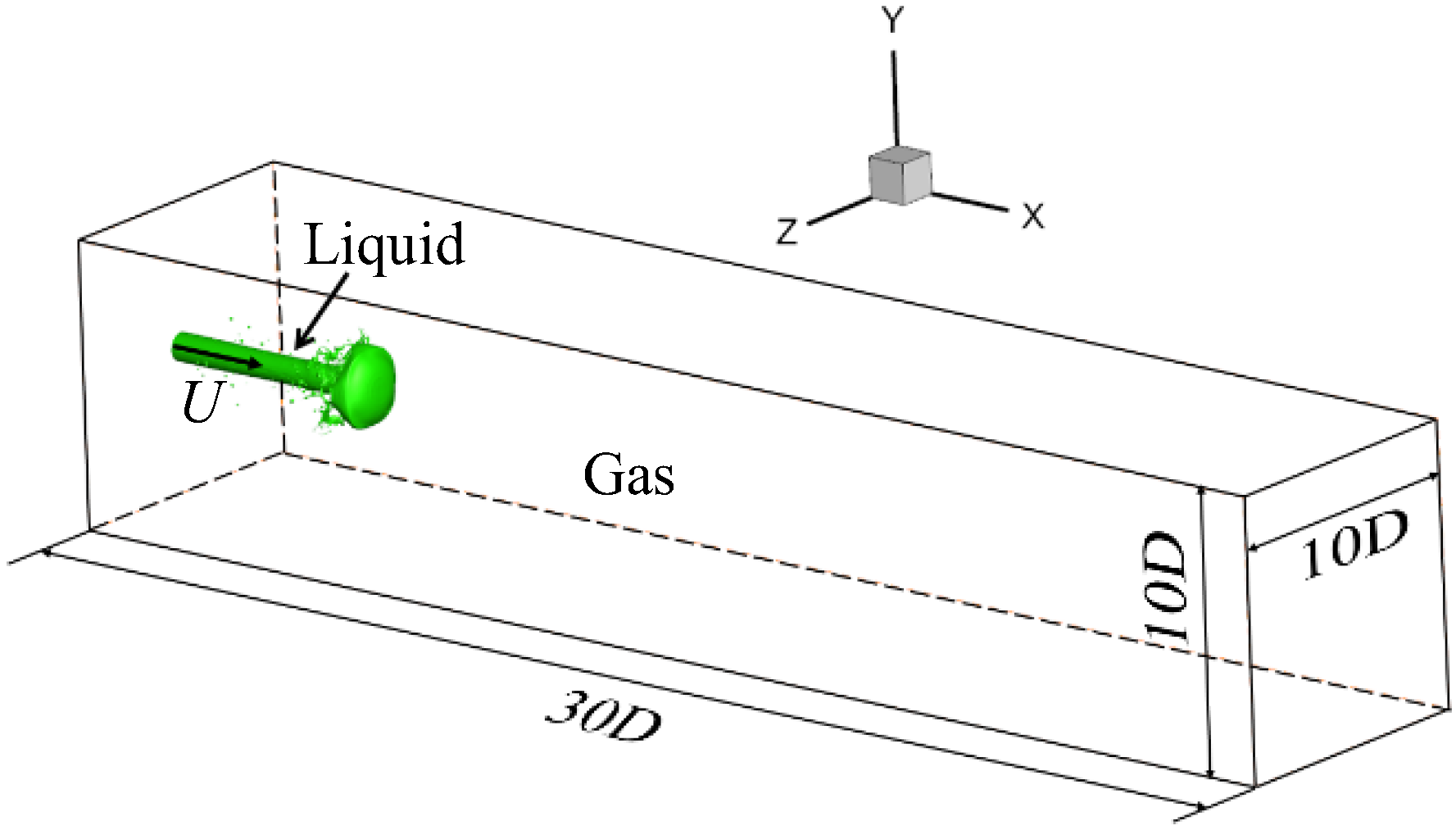
The physical setting of the basic verification case is that a jet of liquid diesel is injected into the static high-pressure gas from a cylindrical hole with a diameter of
D = 100 μm. The properties of the diesel and static gas are shown in
Table 1. The size of the computational domain is
, as shown in
Figure 1. The direction of the liquid jet is along the positive direction of the
x-axis. The velocity boundary condition is adopted for the left inlet, outlet boundary condition is adopted for the right outlet, and symmetrical boundary condition is adopted for the four sides.
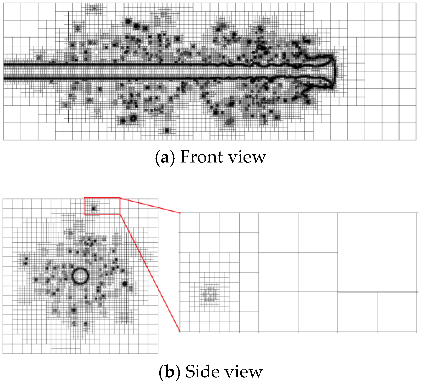
Three different grid resolutions are selected for testing. The maximum scale of the three grids is 0.125 mm, and the minimum grid scale is shown in
Table 2.
Figure 2 shows the distribution of the adaptive mesh of case 3 on the axisymmetric plane. It can be clearly seen that the grid near the gas–liquid interface is densified level by level (darker color), while the grid distribution is sparse for the surrounding gas area.
At
t = 72 μs, the gas–liquid interface of jet breakup under three grid resolutions is shown in
Figure 3. It can be found that the finer the grid size is used, the more complete the atomization structure, including liquid film, liquid filament, liquid ring, and size droplets, can be described. Especially in cases 2 and 3, many fine liquid ligaments were successfully captured upstream of the liquid core, intertwined, and wound around the liquid core to form a ring. At the same time, under the action of gas–liquid relative velocity difference, wave stripes appear on the surface of the liquid jet head.
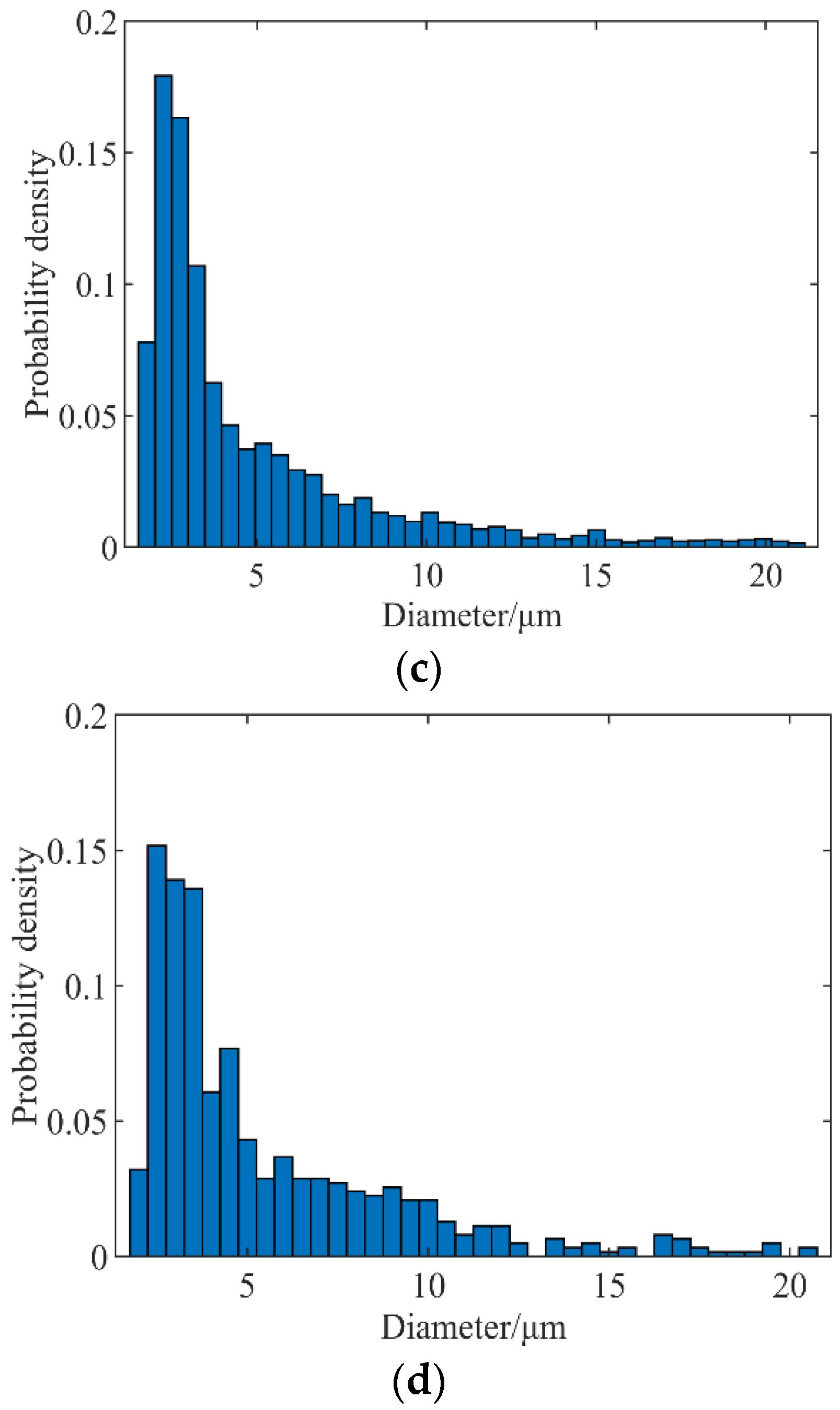
The probability density distribution of droplet diameters, under several cases, are quantitatively compared in
Figure 4. From the droplet diameters corresponding to the peak point of probability density, it can be seen that the droplet diameter corresponding to case 1 is about 8 μm, case 2 is about 4 μm, and case 3 is about 2 μm. The result of case 3 is in good agreement with the results in literature [
4], which shows that refining the grid can enhance the capture ability of small-scale droplet structure.
The results of Sauter mean diameter (SMD) are compared in
Table 3, the relative error between the SMD under the grid resolutions of cases 2 and 3 and corresponding value in the literature were no more than 6%, while case 1 was more than 20%. Therefore, using the minimum grid scale of 0.98 μm can accurately capture the details of the flow field of jet breakup, and there is no need to further refine the grid. Therefore, all simulation calculations in this paper use this grid scale.
4. Calculation Parameters
This work mainly studies the dynamic response of jet breakup, when there is a forced disturbance at the inlet. Based on the basic test case (
Table 1), a flow direction forced sinusoidal disturbance is applied to the velocity at the nozzle with the form of:
where
is the injection velocity of the jet, y is the steady velocity without disturbance,
is the velocity disturbance amplitude, and
is the disturbance frequency. This paper mainly focuses on the frequency response of jet. Therefore, the disturbance amplitude
is taken as a fixed value of 5%.
In order to select the appropriate disturbance frequency, Rayleigh linearized dispersion theory [
27] is introduced. Rayleigh deduced the dispersion equation for the development of surface disturbance of incompressible infinite inviscid jet with linearization theory in 1878. It was revealed that the growth rates of disturbance waves with different wavelengths were different, there was a disturbance wave with maximum growth rate on the jet surface, and the corresponding disturbance wavelength was the dominant wavelength. When the amplitude of the dominant disturbance wave reaches the jet radius, the jet is pinched off into droplets. The droplet diameter and jet penetration can be deduced theoretically. The assumptions of this theory are summarized as (1) the liquid jet is initially stationary in air and an incompressible infinite cylindrical jet; (2) ignoring the viscosity of jet and air; and (3) without considering gravity. The equation is:
where
is the disturbance growth rate,
is the disturbance oscillation frequency,
is the wave number,
,
is the disturbance wavelength,
is the liquid jet radius,
is the liquid jet density,
is the surface tension coefficient, and
and
represent the first kind of modified Bessel function of orders 0 and 1, respectively. When the long wave disturbance
, the growth rate of jet disturbance is greater than 0, and the jet will be unstable. When the short-wave disturbance
, the capillary contraction on the jet surface is limited. Therefore, the jet will be stable. The critical wavelength of jet instability is
. For our cases, the capillary velocity is
, so the jet velocity
[
28]. Therefore, the corresponding theoretical critical disturbance frequency of the jet is
. When the disturbance frequency
f < 95.5 kHz, the amplitude of the jet surface increases gradually, which may lead to the instability of the jet. When
f > 95.5 kHz, the amplitude of jet surface wave decreases gradually, and the jet remains stable.
Figure 5 shows the variation of jet surface disturbance growth rate with dimensionless wave number
kR. It can be seen that when
, the disturbance growth rate reaches the maximum, and the jet surface wave is the most unstable, with a corresponding nozzle disturbance frequency of
. Because the liquid jet and air selected are viscous, in addition, the jet has a velocity and is not infinite, which is different from the theoretical condition, and the range of the disturbance frequency selected in the numerical calculation is expanded to between 0 and 3000 kHz.
5. Results and Discussion
5.1. Overall Structures
Shinjo et al. [
4] have studied the liquid jet breakup process with undisturbed nozzle at three different velocities. Their research shows that the jet atomization mainly occurs at the jet tip edge, under the undisturbed condition of the nozzle. Here, we focus on the coupling effect of nozzle disturbance and jet tip disturbance on jet disintegration. The nozzle velocity disturbance of a certain frequency will form surface waves on the liquid core. The surface wave presents a different evolution process, with time, in different frequencies.
Figure 6 and
Figure 7 show the evolution results with frequencies of 300 and 66.6 kHz, respectively. It can be observed that the amplitude of the surface wave on the liquid core caused by the disturbance of 300 kHz frequency decreases gradually, while the amplitude in 66.6 kHz increases gradually. It is consistent with the results of capillary instability analysis in previous section.
Figure 8 shows the velocity distribution of the gas–liquid interface at 93 μs. The disturbance of different frequencies has different effects on the disintegration of the jet tip. When the frequency is relatively low, the wavelength of the liquid core surface wave (caused by the nozzle disturbance) is longer, and the amplitude of the surface wave gradually increases, resulting in obvious interference to the jet tip. For high-frequency disturbance, the surface wave gradually attenuates in the later stage, and the impact on the jet tip gradually decreases. For example, the shape of the jet head under 66.6 kHz is obviously inconsistent with that under undisturbed and high-frequency disturbance cases. The liquid velocity at the wave node of liquid core fluctuation is higher, and the velocity of surrounding droplets is relatively low.
5.2. Ligament Formation
The results of Shinjo et al. [
1,
4] show that the liquid ligaments can come from the jet tip and liquid core. The ligament formation first occurs at the tip edge, and the nearby vortices determine the direction of ligament formation. The ligament formation strongly depends on its local velocity field and is concentrated near We~O(1); the definition of Weber number is
, where
is the relative velocity between the liquid and gas phases, and
is the baseline radius of the liquid ligament. However, the ligament formation on the liquid core is mainly due to the re-collide of the ligaments and droplets generated by the breakup of the jet tip with the liquid core surface, which will feed disturbances to the surface, accelerating the instability process. One or more ligaments may be generated at one time, and the number of ligaments depends on the initial wave crest shape, wave crest size, and local flow field.
After different frequencies of disturbance are applied to the nozzle, the ligament formation on the jet tip and liquid core is different from the above undisturbed case. According to the results in the previous section, the velocity disturbances of different frequencies form surface waves of different wavelengths on the liquid core, and the surface waves increase or decay with time, thus affecting the breakup of the jet head and surface of the liquid core. The jet head and liquid core surface breakup are coupled to form a complex disintegration mechanism.
Firstly, the ligament formation on the liquid core surface is analyzed. In
Figure 8, the surface wave amplitude with short wavelength gradually attenuates with time, and the liquid core surface tends to be smooth in the later stage (
f = 450, 1500 kHz); however, the temporal evolution of surface wave attenuation also interferes with the temporal evolution of the jet head. Therefore, the process of jet head breakup under high frequency disturbance case is not exactly the same as that of the nozzle without disturbance. This effect decreases with the increase of the disturbance frequency of the nozzle. The statistical analysis of the spray field will be carried out in the next section.
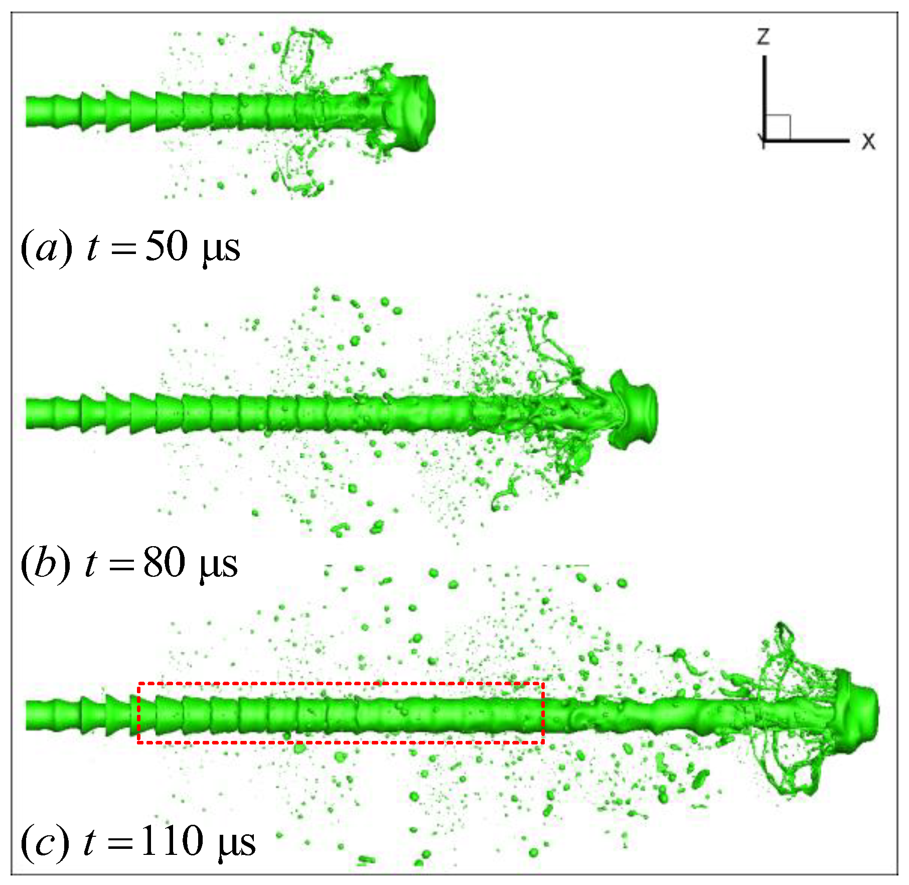
Figure 9 shows the morphological evolution and liquid ligament formation near the jet tip. Different from the undisturbed case, the unstable jet surface wave (also known as “cone crest” by some researchers [
10]) has a great interference on the breakup of the jet tip. It can be clearly seen that the velocity of the cone crest and liquid core is greater than that of the jet tip. When the jet tip is squeezed, a hole appears near the tip edge. The hole continues to expand under the action of surface tension, and a ring-like liquid ligament is formed at the tip edge. Because the velocity of the ring-like ligament is less than that of the crest, the crest continues to move downstream relative to the ligament. The above process is shown by the blue arrow in
Figure 9c–f. Then, the crest merges with the liquid near the tip edge, and several long streamwise ligaments are formed under the tensile action of the ring-like ligament, as shown by the red arrow in
Figure 9e–f. Due to the fusion effect of the crest, the streamwise liquid ligaments, generated here, are longer and thicker than those under undisturbed case.
On the cone crest away from the jet tip, the dynamic process of liquid ligament formation is different, due to the different position of droplet impact and local flow field. The ligament formation on the cone crest, far from the tip, is mainly due to the re-collision between the droplets and the wave crest moving downstream, resulting in the instability and breakup of the wave crest.
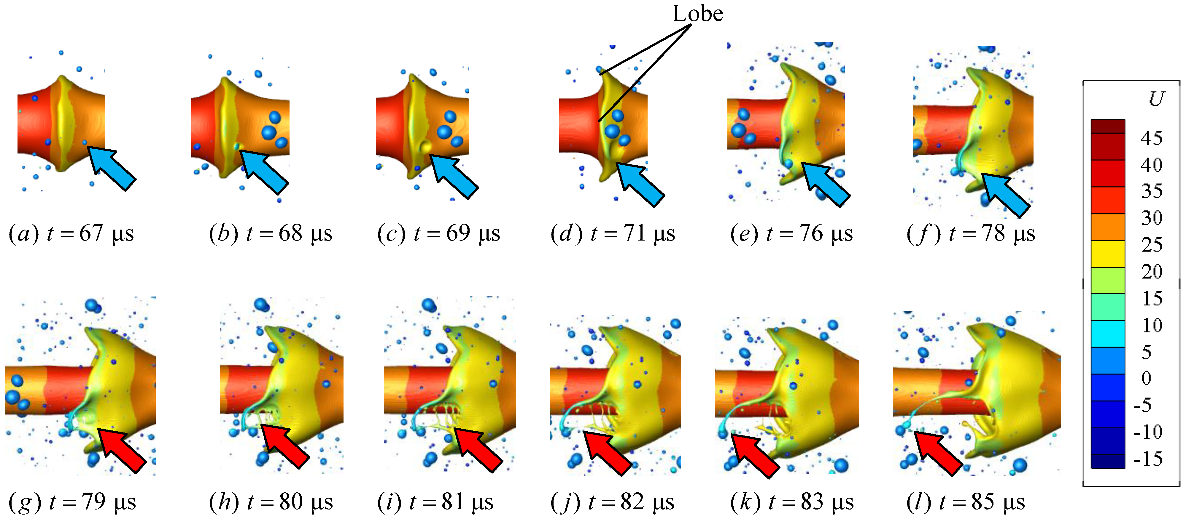
Figure 10 shows one of the ligament formation mechanisms. The instability starts from the initially axisymmetric surface waves. With the development of 3-D character of the instability, the cone crest divides into distinct rounded ‘lobes’, as shown in
Figure 10d. A similar process was observed in the study of Jarrahbashi et al. [
10]. In addition, during the development and stretching of the cone crest, the crest is impacted by a small droplet, which disturbs the crest and produces dents at the lobe near the impact point. This process is shown by the blue arrow in
Figure 10a–f. Then, due to the effect of surface tension, holes are formed near the lobe, the holes continue to stretch and become larger, and a narrow tubular liquid structure is formed between the edge of the lobe and hole near the edge, which was called “rim bridge” by Jarrahbashi et al. [
10].
Here, because there are many holes formed by droplet impact, multiple “middle bridges” appear. Then, under the capillary action, rim bridge, and middle bridges break at the minimum cross-sectional area to form liquid ligaments, and the liquid ligaments formed by the rim bridge are thicker than those formed by the middle bridges. The above process is shown by the red arrow in
Figure 10g–l.
Figure 11 shows the instability of the cone crest closer to the jet tip. Different colored arrows in the figure track the impact of different droplets on the cone crest. As shown by the blue arrows in
Figure 11, when
t = 52 μs, a small droplet collides with the liquid core near the crest, and the crest amplitude is still small. With the gradual increase of the crest amplitude, the disturbance continues to spread to the edge of the cone crest, resulting in an indentation near the lobe. Due to the effect of surface tension, a hole is generated after the indentation is broken, and the hole continues to develop and become larger. The middle bridges are not formed here, which is different from the mechanism shown in
Figure 10. Then, the ligament at the edge of the hole approaches the liquid core under the action of nearby vortex suction, and the axial velocity of the ligament becomes larger, as shown by the blue arrow, when the
t = 78–82 μs. In addition, compared with
Figure 10, the impact frequency of droplets on the crest is greater. Since the cone crest here is closer to the jet head, more droplets, generated by the edge of the jet tip, collide with the crest here, so as to induce more holes on the crest surface. This process promotes the instability of the cone crest and produces more liquid ligaments. In
Figure 11, arrows of different colors show the process of droplets hitting cone crest at different positions.
5.3. Droplet Formation
Shinjo et al. [
4] have reported that droplets are mainly formed from the tip of the liquid ligaments in a short-wave mode, in which the propagating capillary wave is generated by the contraction movement of the tip, and the pinch-off wavelength is about 3–4 times of the baseline radius of the ligament. Their results show that the instability of the liquid ligament is due to the stretching of the ligament, instead of the development of the most unstable wave (
). Therefore, the process of droplet formation of ligaments could not be consistent with the Rayleigh instability experiment. Shao et al. [
29] found two droplet formation mechanisms of the swirling liquid film, based on Gerris code, namely liquid film and ligament breakup. Similar phenomena can also be observed in the cases in this paper.
Here, we focus on the characteristics of the whole spray field caused by the disturbance frequency of the nozzle. In previous work [
30], we discussed the evolution of SMD and volume of atomization with perturbation frequency.
Figure 12 shows the cumulative probability density distribution of sphericity, normalized by the volume of injected liquid. The sphericity adopted here is the ratio of
D32 and
D30. It can be found that the curves, corresponding to the frequencies range of 66.6 kHz–1260 kHz, deviate greatly from the undisturbed case. When the frequency increases from 66.6 kHz to 150 kHz, the droplet volume decreases rapidly.
Figure 13 shows the proportion of droplets with sphericity above 0.9. It can be seen that, with the increase of nozzle disturbance frequency, the volume fraction of spherical droplets in the shed liquid presents a fluctuating result. The frequency with the smallest proportion of spherical droplets is 150 kHz, only 13.7%. At this frequency, the proportion of highly deformed droplets is larger, which will promote the subsequent secondary breakup. At high frequency, it is gradually close to the case of no disturbance. It shows that, in a certain frequency range, the velocity disturbance at the nozzle will affect the formation of spherical droplets, resulting in a larger proportion of irregular droplets, which promotes the further fragmentation of droplets.
The cumulative density function of the atomized liquid fraction is shown in
Figure 14, which can be seen at time 93 μs; the atomization volume is the largest at 30 kHz and smallest at 300 kHz under the cases of 11 different nozzle disturbance frequencies. They account for 8.07% and 4.96% of the injected liquid respectively. The maximum atomization volume is 62.7% higher than the minimum atomization volume, indicating that the atomization effect of different nozzle disturbance frequencies is obviously different. The curve with disturbance frequency of 30 kHz (blue dotted line) and curve with disturbance frequency of 66.6 kHz (black dotted line) are above the curve corresponding to undisturbed case (red dotted line) when the droplet diameter is less than 50 μm, indicating that the proportion of small droplets generated by disturbance frequency below 66.6 kHz is higher than that under undisturbed case. However, when the nozzle disturbance frequency continues to increase to 150 kHz, the curve (magenta dotted line) is always below the undisturbed red curve, indicating that the disturbance of this frequency has a slowing effect on the overall atomization, and the rate of producing small droplets is lower than that without disturbance. When the disturbance frequency is 300 kHz (red solid line), the slowing effect is more obvious.
From the range of 0–300 kHz, it can be found that, when the disturbance generated by the nozzle increases gradually (f = 30, 66.6 kHz), the proportion of small droplets below 20 μm is greater than that under the undisturbed case. At 150 and 300 kHz, the corresponding disturbance is attenuated, and the small droplet ratio is less than that under undisturbed case.
When the droplet diameter is less than 20 μm, the blue and black solid lines, corresponding to the cases of the disturbance frequency of 450 and 600 kHz, are above the red dotted line, indicating that the disturbance in this frequency range can promote the formation of small droplets. In addition, no large droplets of more than 50 microns are produced, and the total atomization volume is still smaller than the undisturbed condition. Therefore, the disturbance in this frequency range also promotes the uniformity of atomization and produces fewer large-sized liquid clusters and liquid filaments, which is more conducive to subsequent stable combustion. In the frequency range of 1260 to 2100 kHz, the curve gradually approaches the undisturbed case. However, when the frequency further increases, at 3000 kHz, the curve gradually deviates from the undisturbed case, the proportion of small droplets decreases, and the atomization process slows down.


