Article

Energy-Efficient Trajectory Optimization for UAV-Enabled Cellular Communications Based on Physical-Layer Security

1
Institute of Engineering Thermophysics, Chinese Academy of Sciences, Beijing 100190, China
2
Army Academy of Artillery and Air Defense, Hefei 230031, China
*
Author to whom correspondence should be addressed.
Aerospace 2022, 9(2), 50; https://doi.org/10.3390/aerospace9020050
Submission received: 2 December 2021 / Revised: 13 January 2022 / Accepted: 17 January 2022 / Published: 20 January 2022
(This article belongs to the Special Issue Energy Efficiency of Small-Scale UAVs)

Abstract

:
Low-altitude cellular-enabled Unmanned Aerial Vehicles (UAVs) provide potential supplementary platforms to assist air-to-ground cooperative communication. This paper investigates a joint safety information interaction scheme for a UAV-enabled network, which involves the complex constraints of three-dimensional trajectory planning, average energy efficiency optimization, and physical-layer security. Specifically, by modeling the UAV and the Ground Station (GS) as the transmit sources, we define the secure Energy Efficiency (EE) as the ratio of the total secrecy rate to the energy consumption of the whole system. Then, to achieve secure and energy-efficient communication in eavesdropping scenarios, we formulated the optimization problem as maximizing both the uplink/downlink secure EE of the system, subject to the constraints of the UAV’s mobility and the allowable transmit power. For this highly coupled non-convex problem, a composite solution of joint fractional programming, alternate optimization, the bisection method, and the interior-point method is proposed to obtain the achievable EE. Simulation and performance analysis gave the conclusions that the joint optimization of trajectory and power allocation is capable of maximizing the information secure EE. Additionally, the secure EE increases with the increase of the average transmit power, which finally tends to be stable.

1. Introduction

High-altitude large-range communication and low-altitude high-density communication are two major development directions of aerial-platform-assisted communication, as shown in Figure 1. The former is represented by the High-Altitude Long-Endurance (HALE) Solar-Powered UAVs (SP-UAVs) [1] and SpaceX’s Starlink Network [2]. Benefited by the advantages of orbit resources, spectrum resources, long endurance at high altitude, and wide coverage, these platforms have the potential to provide emergency communications and high-quality communications in remote areas [3,4]. The low-altitude platforms are represented by tethered aerostats/UAVs, relaying communication UAVs, etc., which serve as an efficient supplement to Fourth-Generation (4G) and Fifth-Generation (5G) communication [5]. In particular, 5G communication demands massive Base Stations (BSs) to achieve dense communication coverage, which requires significant costs. Compared with ground BSs, low-altitude UAV-enabled BSs have the advantages of low cost, high efficiency, effective coverage enhancement, and flexible deployment [5,6,7]. Therefore, the applications of low-altitude platforms have begun to attract the extensive attention of academic researcher, especially the construction of the universal network of the integration of the heavens and Earth.
The challenges of implementing the low-altitude UAV-assisted communication involve delay, energy consumption, interference avoidance, information security, etc. Firstly, as to the energy consumption problem, the UAV-aided platform is inevitably limited by energy (batteries or oil). However, the aerial BS communication is generally expected to be sustainable and have wide coverage [5]. To solve this problem, trajectory optimization provides a solution that can use restricted energy to achieve more mission gains, especially when the energy bottleneck cannot be broken (at present, the battery density bottleneck is less than 400, while oil-powered UAVs generally fly in dozens of minutes to several hours). Secondly, the ground BS generally has problems such as occlusion and fading, which can be alleviated to some extent in the air, benefited by the mobility of UAVs. On the other hand, the UAV also needs to optimize its path according to the channel environment [8]. Many research works have focused on the joint optimization of energy limitation and fading via path planning. Reference [5] optimized the UAV’s trajectory with the consideration of both communication throughput and energy consumption, and Reference [9] formulated the optimization problem subject to the maximum tolerable signal leakage of the eavesdropper and the minimum data rate requirement of each user, to maximize the system EE by the joint design of resource allocation and the trajectory. Additionally, the EE was maximized by jointly optimizing the backscatter devices’ scheduling, the carrier emitters’ transmission power, and the UAV’s trajectory in [10].
The second important problem of a UAV-assisted network that should be considered is information security. As shown in Figure 2, UAVs not only need to consider the normal receiving of their own remote control and telemetry signals, but also need to consider the information security of their payload, to avoid malicious interference and eavesdropping. To cope with such a problem, physical-layer security is exploited as an alternative security technology. The physical-layer security protects the communication phase of the network by exploiting the imperfections of the communication medium [11]. Compared to cryptography, it uses the randomness of the physical medium and the difference between the legitimate channels and the eavesdropping channels, with the advantages of dispensing with the encryption key, lower computational complexity, and resources savings [12,13]. Therefore, physical-layer security is suitable to be applied in the UAV-assisted network. However, there are two challenges in the application: (1) the difference between the uplink channel and downlink channel; (2) the variable dimensions of joint optimization, especially power, which is the most important factor of the constraint choices. Many researchers are concerned about the related investigations/ The achievable secrecy rate was improved by the transmit jamming approach for the randomly deployed UAV-enabled multi-antenna mmWave communication networks in [14]. Analogously, the jamming policy of the jammer UAV was also applied to maximize the system energy efficiency in [15], the joint optimization with the resource allocation and the trajectory of the information UAV. Furthermore, the system security EE was maximized by jointly optimizing the UAV trajectory, transmit power, and user scheduling subject to the constraints of both UAV mobility and peak transmit power in [16], while the average transmit power was not taken consideration. In [17], the secrecy EE maximization problem was investigated via jointly optimizing the communication scheduling, the source/relay power allocation, and the UAV trajectory in a UAV-enabled mobile relaying system. Specifically, the research referring to the uplink channel is a new focus direction, which has attracted the attention of researchers.
The above-analyzed aspects constitute the complex constraints that the UAV-enabled communication must consider, that is the three-dimensional trajectory planning, the average energy efficiency optimization, and the physical-layer security. Based on the above background, this paper intends to investigate the joint energy-efficient and security scheme for both the uplink and downlink of the UAV-enabled system. Explicitly, our objective was to maximize the secure EE via jointly considering the secrecy rate and the system’s energy consumption. The difficulty is that maximizing the secrecy rate requires the UAV to be closer to ground stations and farther away from eavesdroppers. Meanwhile, the maneuverability of the UAV also needs to be considered, of which the path planning needs to strike an optimal balance between maximizing the secrecy rate and minimizing the system’s energy consumption.
Tackling the above challenges, the contributions are briefly summarized as follows:
(1)
A UAV-assisted communication scheme was studied, which combines the average transmit power, the peak transmit power, path planning, and both the uplink and downlink secure EE;
(2)
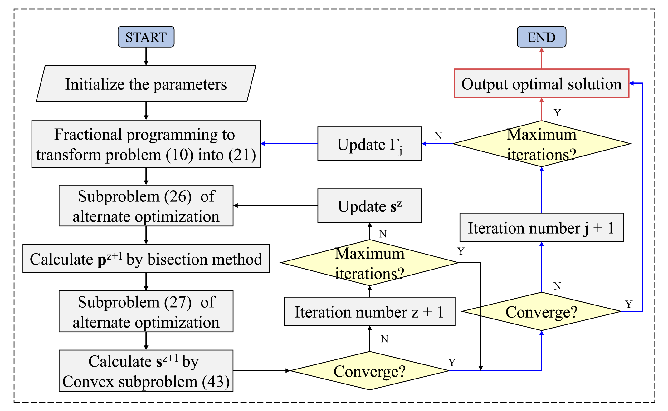
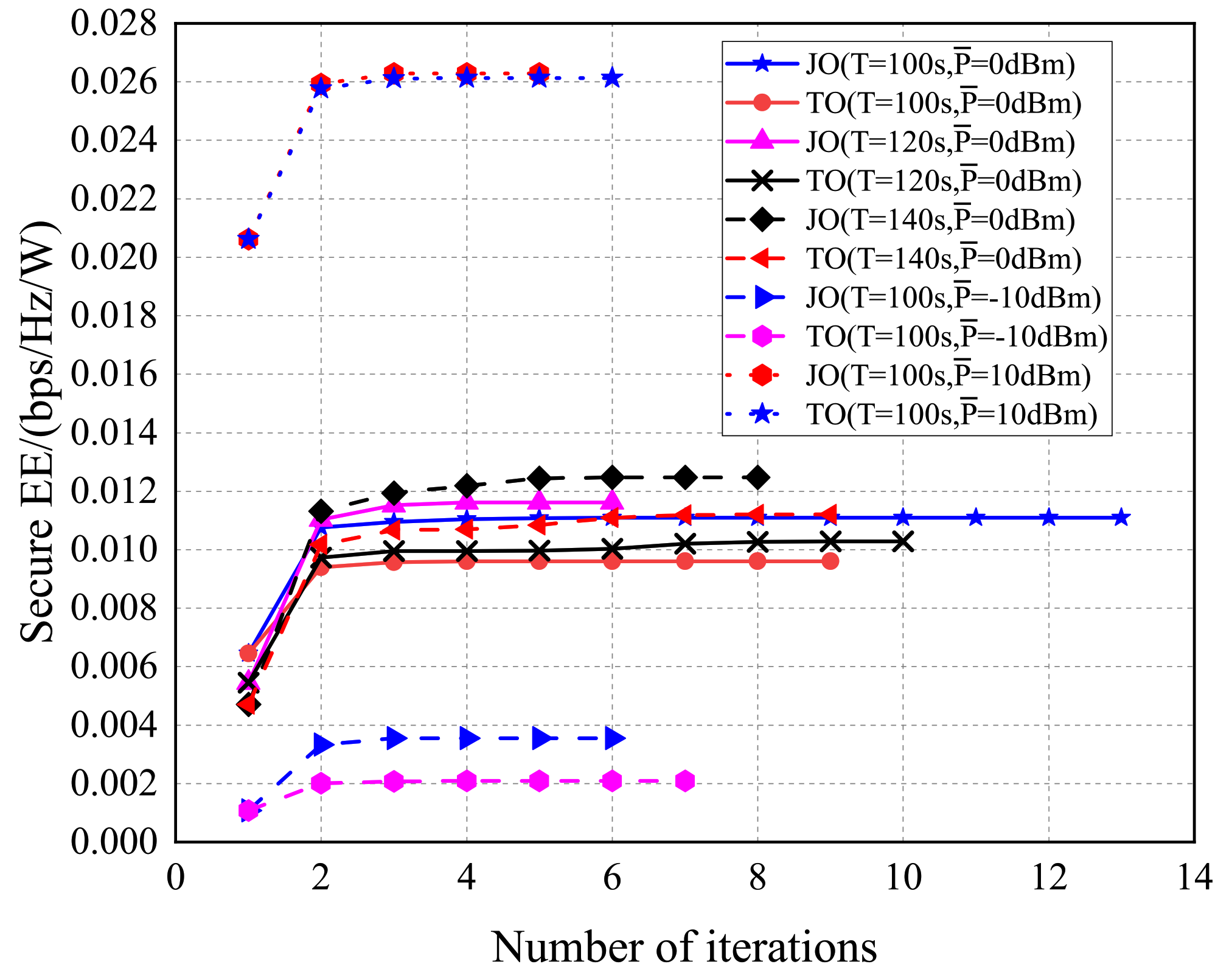
Due to the optimization problems and constraints having strong coupling and non-convexity, a composite solution of joint fractional programming, alternate optimization, the bisection method, and the interior point method is proposed to solve the problem, which can quickly obtain the optimal trajectory and transmit power;
(3)
The variation trend of secure EE affected by the average power and flight time was analyzed. Generally, secure EE improves with the increase of the average transmit power in the downlink and converges to a stable value as the flight time increases;
(4)
Compared with the comparable benchmarks, the proposed scheme achieved a higher secure EE. In the downlink communication, the secure EE was improved at least 12%, which is four-times that of the worst benchmark scheme. For uplink channels, the secure EE improved by at least 13%, which is two-times that of the worst benchmark.
The rest of this paper is arranged as follows: Section 2 describes the system model and power consumption model, as well as the problem formulation. Then, the proposed method solving the problem is expounded in Section 3. According to the solution scheme, the simulation results are demonstrated in Section 4. The conclusions are summarized in Section 5 finally.

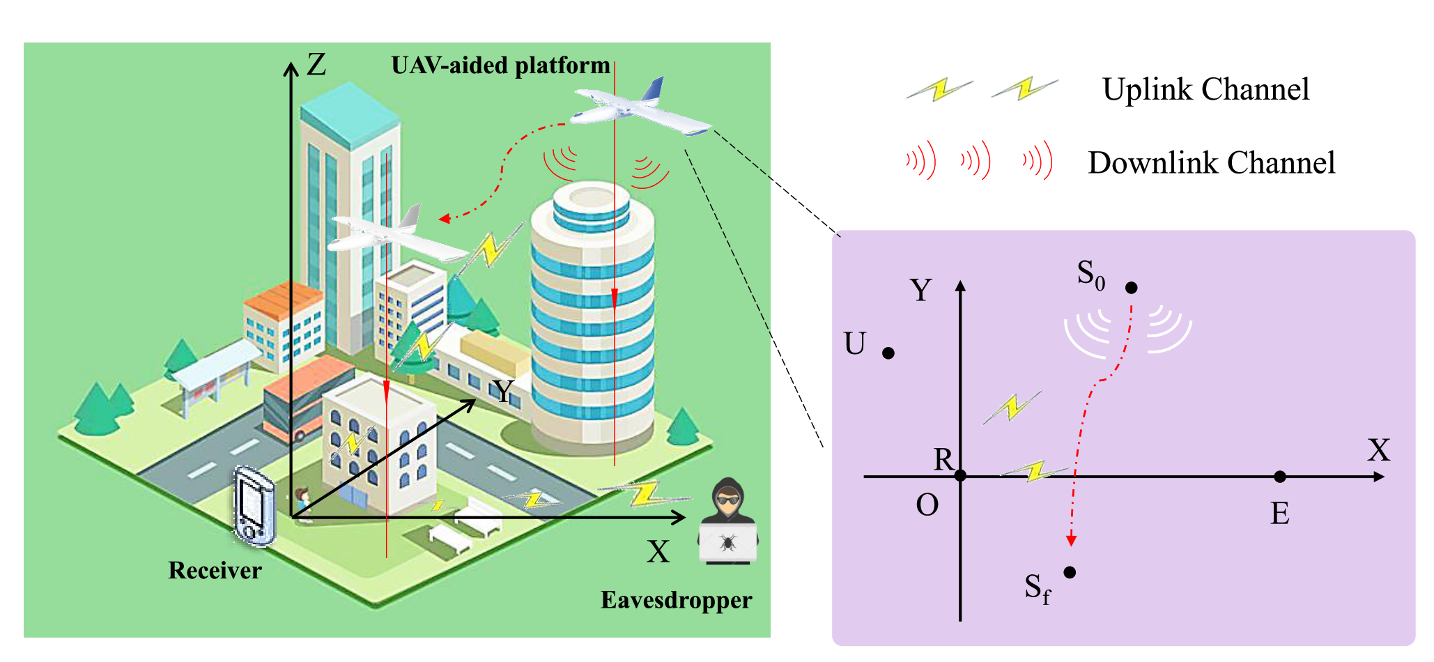
2. System Model and Problem Formulation

The UAV-assisted wireless communication system is composed of a fixed-wing UAV and a ground station. Reference [18] investigated the influence of the path loss compensation factor and aerial base stations’ altitude on the users’ coverage probability. However, in this paper, our attention is on one legitimate user, so the users’ coverage probability is not a significant factor. For convenience, we considered that the UAV, which is denoted by U, flies at a constant height H, which depends on the surrounding environment, and is capable of ensuring the flight safety and satisfying the requirements of the mission. For the uplink and downlink communication, the channel between the eavesdropper and the ground station is modeled as a combination of distance-dependent path loss and the small-scale Rayleigh fading, while the communication between the ground node to the UAV can be modeled as the Rician channel or Line-of-Sight (LoS) channel.
Then, the following assumption are needed throughout the paper. The UAV knows the location of the ground station, and if the UAV is equipped with an optical camera or Synthetic Aperture Radar (SAR), it will detect the location of the eavesdropper [19]. For simplicity, there is no loss of generality in assuming that the ground station denoted by R and the eavesdropper denoted by E are at the same altitude. Figure 3 is the system’s three-dimensional (3D) model and its horizontal plane. Define the horizontal line between R and E as the X-axis. Meanwhile, let D denote the distance between the ground node and the eavesdropper, then the corresponding coordinates of the ground node and the eavesdropper are s r = ( 0 , 0 ) and s e = ( D , 0 ) . Furthermore, for the UAV, let T denote the total flight time, s 0 and s f denote the coordinates of its initial and final positions, and v 0 and v f denote its initial and final velocities. Those parameters were determined before the optimization. For convenience, we divided the overall flight duration T into N time slots, and each time slot is denoted by δ t . Next, since the two scenarios were modeled diversely, we discuss them respectively.

2.1. Downlink Scenario

The energy-efficient physical-layer security for the downlink channel of the UAV-assisted wireless communication system was investigated first. We denote the UAV’s trajectory by s = s [ 1 ] , s [ 2 ] , , s [ N + 1 ] T and the transmit power by p = p [ 1 ] , p [ 2 ] , , p [ N ] T for convenient expression. Our goal was to maximize the average secure EE denoted by Γ s , p , which is defined as the ratio of the total secrecy rate to the energy consumption of the whole system, with the constraints of the UAV’s trajectory s and the transmit power p .

2.1.1. System Model

As shown in Figure 3, the UAV broadcasts information to the ground station. Due to the eavesdropper and ground station being on the ground, the channels between them to the UAV are regarded as LoS communication. Considering that δ t is sufficiently small, in the ith time slot, we may actually assume that the UAV’s transmit power p [ i ] , position s [ i ] , velocity v [ i ] , and acceleration a [ i ] are constant. Then, the channel power gain from the UAV to the ground receiver in this time slot is:
h UR [ i ] = β 0 s [ i ] s r 2 + H 2 ,
where β 0 denotes the channel power gain at the reference distance d 0 = 1 m. Accordingly, the channel rate from the UAV to the ground node can be obtained by:
R UR [ i ] = log 2 1 + γ 0 p [ i ] s [ i ] s r 2 + H 2 ,
where γ 0 = β 0 / σ 2 is the reference signal-to-noise ratio (SNR) and σ 2 is the additive white Gaussian noise power. Similarly, the eavesdropper’s achievable rate received from the UAV is given by:
R UE [ i ] = log 2 1 + γ 0 p [ i ] s [ i ] s e 2 + H 2 .
Thus, for this UAV-assisted wireless communication system, the achievable average secrecy rate ( b p s / H z ) during the entire flight can be calculated by Equation (4), where [ a ] + = max a , 0 .
R ¯ s e c = 1 N i = 1 N log 2 1 + γ 0 p [ i ] s [ i ] s r 2 + H 2 log 2 1 + γ 0 p [ i ] s [ i ] s e 2 + H 2 + .
Evidently, as the position of the UAV changes, the secrecy rate also changes.

2.1.2. Energy Model

According to [5], the consumption of transmit power can be ignored compared with the UAV’s propulsion energy consumption. By choosing v 0 = v f , we may obtain the UAV’s average propulsion power through Equation (5), in which c 1 and c 2 are two parameters determined by the UAV’s property and the flight environment and g is the gravitational acceleration.
E ¯ s e c = 1 N i = 1 N c 1 v [ i ] 3 + c 2 v [ i ] 1 + a [ i ] 2 a [ i ] v T [ i ] 2 v [ i ] 2 g 2 .

2.1.3. Optimization Problem Formulation

The value of secure EE is defined by the ratio of the system’s secrecy rate to the energy consumption. Specifically, the average secure EE of the overall flight can be formulated as Equation (6) by substituting Equations (4) and (5).
Γ s , p = R ¯ s e c s , p E ¯ s e c s , p = i = 1 N log 2 1 + γ 0 p [ i ] s [ i ] s r 2 + H 2 log 2 1 + γ 0 p [ i ] s [ i ] s e 2 + H 2 + i = 1 N c 1 v [ i ] 3 + c 2 v [ i ] 1 + a [ i ] 2 a [ i ] v T [ i ] 2 v [ i ] 2 g 2 .
In practice, we maximize the average secure EE with the considerations of the UAV’s mobility constraints and transmit power constraints. Thus, the optimization problem of the downlink channel can be formulated as:
max s , p : Γ s , p s . t . s [ 1 ] = s 0 , v [ 1 ] = v 0 , s [ N + 1 ] = s f , v [ N + 1 ] = v f , v [ i + 1 ] = v [ i ] + a [ i ] δ t , s [ i + 1 ] = s [ i ] + v [ i ] δ t + 1 2 a [ i ] δ t 2 , i = 1 , , N , v [ i ] v max , a [ i ] a max , 1 N i = 1 N p [ i ] P ¯ , 0 p [ i ] P max , i = 1 , 2 , , N ,
where v [ i ] and a [ i ] respectively mean the Euclidean norm of v [ i ] and a [ i ] .
Next, we explain the constraints in detail. In Problem (7), as the initial and final positions and velocities of UAV denoted by s 0 , s f , v 0 , and v f have been determined, we have the following constraints:
s [ 1 ] = s 0 , v [ 1 ] = v 0 , s [ N + 1 ] = s f , v [ N + 1 ] = v f .
Furthermore, the location and velocity in ( i + 1 ) th time slot are related to those of ith time slot, which can be expressed as:
v [ i + 1 ] = v [ i ] + a [ i ] δ t , s [ i + 1 ] = s [ i ] + v [ i ] δ t + 1 2 a [ i ] δ t 2 .
Then, the UAV’s maximum velocity and acceleration are called v max and a max , which depend on the mobility of the UAV. For random i, the Euclidean norm of v [ i ] is no more than v max ; meanwhile, that of a [ i ] does not exceed a max ; thus, these constraints can be expressed as:
v [ i ] v max , a [ i ] a max .
Moreover, the UAV’s transmit power p [ i ] is limited by the peak power, which is denoted by P max . For the average transmit power during the overall flight, it is no more than a given average transmit power denoted by P ¯ :
1 N i = 1 N p [ i ] P ¯ , 0 p [ i ] P m a x .

2.2. Uplink Scenario

For the energy-efficient physical-layer security of the UAV-enabled wireless communication system, there are some similarities between the uplink and downlink scenarios. Let us denote the ground node’s transmit power by q = q [ 1 ] , q [ 2 ] , , q [ N ] T and the secure EE of the uplink scenario by Γ s , q for the convenience of presentation. Next, we only analyze the differences.

2.2.1. System Model

In the uplink communication, the ground station broadcasts a message to the UAV. The communication from it to the UAV can be still regarded as the LoS channel; thus, this channel rate in the ith time slot can be calculated by Equation (2) via replacing the UAV’s transmit power p with the ground station’s transmit power q .
However, the channel between the eavesdropper and the ground station is modeled as a combination of distance-dependent path loss and small-scale Rayleigh fading. Therefore, the power gain of this channel is:
h RE = β 0 D κ μ ,
where μ is the exponential distribution random variable with unit mean and κ is the pass-loss exponent. Explicitly, log 2 1 + γ 0 q [ i ] D κ μ has the property of being concave. By Jensen’s inequality, an upper bound of the achievable rate from the ground node to the eavesdropper can be calculated by:
R RE [ i ] = E μ log 2 1 + γ 0 q [ i ] D κ μ log 2 1 + γ 0 q [ i ] D κ E μ [ μ ] = log 2 1 + γ 0 q [ i ] D κ ,
where E μ f ( μ ) stands for the mathematical expectation of function f ( μ ) with variable μ .
Accordingly, the achievable average secrecy rate ( b p s / H z ) of the uplink can be calculated by Equation (14).
R ¯ s e c = 1 N i = 1 N log 2 1 + γ 0 q [ i ] s [ i ] s r 2 + H 2 log 2 1 + γ 0 q [ i ] D κ + .

2.2.2. Optimization Problem Formulation

The system’s overall energy consumption of uplink communication is similar to the downlink channel, then the optimization problem is formulated as:
max s , q : Γ s , q = i = 1 N log 2 1 + γ 0 q [ i ] s [ i ] s r 2 + H 2 log 2 1 + γ 0 q [ i ] D κ + i = 1 N c 1 v [ i ] 3 + c 2 v [ i ] 1 + a [ i ] 2 a [ i ] v T [ i ] 2 v [ i ] 2 g 2 s . t . s [ 1 ] = s 0 , v [ 1 ] = v 0 , s [ N + 1 ] = s f , v [ N + 1 ] = v f , v [ i + 1 ] = v [ i ] + a [ i ] δ t , s [ i + 1 ] = s [ i ] + v [ i ] δ t + 1 2 a [ i ] δ t 2 , i = 1 , , N , v [ i ] v max , a [ i ] a max , 1 N i = 1 N q [ i ] Q ¯ , 0 q [ i ] Q max , i = 1 , 2 , , N .
In Problem (15), the optimization problem is also restricted by the UAV’s mobility and the average and peak ground station’s transmit power, denoted by Q ¯ and Q max .
Remark 1.
In summary, the differences between the downlink and uplink scenarios are listed as follows:
(1) 
The transmit sources of downlink and uplink scenarios are different, as the former is the UAV, while the latter is the ground station;
(2) 
The channels from the transmit sources to the eavesdropper of the two scenarios are distinct. Explicitly, the two channels are respectively air-to-ground communication and ground-to-ground communication.

3. Secure EE Maximization

In Primal Problems (7) and (15), the objective functions are expressed as the form of a fraction, which results in difficulties in solving them. To the best of our knowledge, there is not a standard method to deal with such non-convex problems. Therefore, we introduced some optimization approaches such as fractional programming and alternate optimization, to design a low-complexity solution scheme, whose flowchart is demonstrated in Figure 4. Since the problems (7) and (15) have a homologous construction, we solved Problem (7) subsequently. In particular, for Problem (15), we only demonstrate the different parts between its method and the method of Problem (7).

3.1. Fractional Programming

We firstly denote the maximum secure EE, the optimal trajectory, and transmit power by Γ * and ( s * , p * ) , respectively. Thus, Γ * can be calculated as:
Γ * = R ¯ s e c s * , p * E ¯ s e c s * , p * = max ( s , p ) W R ¯ s e c s , p E ¯ s e c s , p ,
where W is the feasible domain of Problem (7). Then, we introduce Lemma 1 according to [20,21].
Lemma 1.
The maximum secure EE of the problem (7) can be achieved if and only if:
max ( s , p ) W R ¯ s e c s , p Γ * E ¯ s e c s , p = R ¯ s e c s * , p * Γ * E ¯ s e c s * , p * = 0 ,
for R ¯ s e c s , p 0 and E ¯ s e c s , p > 0 , ( s , p ) W .
Accordingly, solving the problem (7) is equivalently transformed into searching for the optimal solution Γ * and ( s * , p * ) for the following problem:
max ( s , p ) W R ¯ s e c s , p Γ E ¯ s e c s , p .
Specifically, adopting the fractional programming algorithm to solve Problem (18), at the ( j + 1 ) th iteration, Γ j is a given parameter to solve the following subproblem:
max ( s , p ) W R ¯ s e c s , p Γ j E ¯ s e c s , p .
Then, let ( s , p ) Γ j denote the optimal solution of Subproblem (19); thus, the secure EE Γ j + 1 calculated at this iteration is obtained by:
Γ j + 1 = R ¯ s e c s , p Γ j E ¯ s e c s , p Γ j .
The specific steps of fractional programming are shown in Algorithm 1. For fractional programming, the iterations are supposed to be terminated when Equation (17) is satisfied. However, considering the time consumption of the calculation, we chose a maximum allowed number of iterations J and define the following stop condition for the algorithm with a given convergence tolerance:
R ¯ s e c s , p Γ j E ¯ s e c s , p ε ,
where ε is a given convergence tolerance. Reference [13] indicated that the sequence Γ j generated by the fractional programming algorithm is convergent. In summary, solving Problem (7) is equivalent to dealing with the parametric programming problem (18) in the condition of Equation (17). Next, the parametric programming problem (18) can be solved through solving the subproblem (19) iteratively.
Algorithm 1: Fractional programming algorithm.
Input: 
γ 0 , H, c 1 , c 2 , g
Output: 
Γ * , s * , p *
1:
Choose an appropriate initial value Γ 0 , and set the iteration time j = 0 ;
2:
repeat
3:
  For the given Γ j , solve Problem (19) to obtain ( s , p ) Γ j (alternate optimization);
4:
  Calculate Γ j + 1 by Equation (20);
5:
   j = j + 1 ;
6:
until the constraint (21) or j > J is satisfied;
7:
return  Γ * = Γ j , ( s * , p * ) = ( s , p ) Γ j 1 .
Then, our goal is to obtain the optimal solution of Subproblem (19), denoted by ( s , p ) Γ j , which is still challenging due to the non-convexity of the objective function with respect to s and p . To solve this problem, we employed alternate optimization, which minimizes (or maximizes) a function jointly over all variables by iteratively alternating minimizations over the individual subsets of variables [22]. For Problem (19), partition the variables into p and s two subsets. Explicitly, Problem (19) is transformed into two steps iteratively: one is optimizing the transmit power p with a given UAV trajectory s , while the other is optimizing the UAV trajectory s with a given transmit power p . We present the two steps in detail next.

3.2. Alternate Optimization

For convenience, we firstly reformulate Problem (19) as:
max ( s , p ) W G s , p = Δ R ¯ s e c s , p Γ j E ¯ s e c s , p .
Then, based on the above analysis, at the ( z + 1 ) th iteration of alternate optimization, the first step is to optimize the transmit power p with a given UAV trajectory s z :
max ( s z , p ) W G s z , p ,
where z represents the zth iteration of the alternate optimization algorithm.
Afterwards, we denote the solution of Problem (23) by p z + 1 . The next step is to optimize the UAV trajectory s with the calculated transmit power p z + 1 :
max ( s , p z + 1 ) W G s , p z + 1 .
Let s z + 1 denote the optimal solution of Problem (24). Via the two steps, now we obtain the optimal solution at the ( z + 1 ) th iteration, which is denoted by s z + 1 , p z + 1 . Similar to fractional programming, a preset maximum allowed number of iterations was chosen for z as Z, and the stop condition of alternate optimization algorithm is given with a convergence threshold ζ :
G s z + 1 , p z + 1 G s z , p z ζ .
The steps of alternate optimization are detailed in Algorithm 2, which is also suitable for the uplink scenario. Observing the two steps of alternate optimization, we deal with the difficulty of how to obtain the optimal solution of each step at the ( z + 1 ) th iteration next. Explicitly, subsequently, we focus on solving Subproblems (23) and (24).    
Algorithm 2: Alternate optimization algorithm.
Input: 
Γ j
Output: 
( s , p ) Γ j
1:
Choose an appropriate starting point ( s 0 , p 0 ) W , and set the iteration time z = 0 ;
2:
repeat
3:
  For the given s z , solve Subproblem (23) to obtain the optimal solution p z + 1 (bisection method);
4:
  Based on the calculated p z + 1 , search for the optimal solution s z + 1 of Subproblem (24) (convex programming);
5:
   z = z + 1 ;
6:
  Calculate G s z , p z ;
7:
until the constraint (25) or z > Z is satisfied;
8:
return  ( s , p ) Γ j = s z , p z .

3.3. Bisection Method

In the first step, the UAV’s transmit power p is optimized with a given UAV trajectory s z for the downlink communication. When the UAV’s trajectory s z is given, both its velocity v z and acceleration a z are determined. By substituting Equations (4) and (5) into Problem (23) and ignoring the constant terms, which have no effect on the problem, Problem (23) is transformed into:
max ( s z , p ) W i = 1 N log 2 1 + k i p [ i ] log 2 1 + l i p [ i ] + ,
where:
k i = γ 0 s z [ i ] s r 2 + H 2 ,
and:
l i = γ 0 s z [ i ] s e 2 + H 2 .
In terms of Problem (26), Reference [23] indicated that its optimal solution p z + 1 is given by:
p z + 1 i = min p ^ i + , P m a x k i > l i , 0 k i l i ,
where:
p ^ i = 1 2 l i 1 2 k i 2 + 1 λ 1 l i 1 k i 1 2 l i 1 2 k i .
In Equation (30), the parameter λ is a constant, which ensures p z + 1 in the feasible domain. Searching for values via the bisection method, for convenience, the search range should be calculated first. Evidently, λ is a positive constant, and p ^ i increases with the decrease of λ . Thus, according to the given s z , we can obtain a group λ ^ by substituting p ^ i = 0 and p ^ i = P max into Equation (30). The minimum and maximum are the left and right boundaries of the search range, respectively.
Especially, for Problem (15), the optimal solution of the ground station’s transmit power q z + 1 can be calculated by Equations (26)–(28), through replacing the UAV’s transmit power p with the ground station’s transmit power q and replacing l i with l, which is calculated by:
l = γ 0 D κ .

3.4. Convex Approximation

In this subsection, we aim at solving Subproblem (24) with a given p z + 1 . Distinctly, both the objective function and the constraints of Problem (24) are non-convex. Refer to [24]. The Sequential Parametric Convex Approximation (SPCA) method is capable of dealing with the problem whose objective function is convex and the constraints are non-convex. Thus, in order to solve Problem (24), we transformed the objective function into its concave lower bound. Firstly, Equation (32) is known to hold evidently.
1 + a [ i ] 2 a [ i ] v T [ i ] 2 v [ i ] 2 g 2 1 + a [ i ] 2 g 2 .
Afterwards, we set P i z + 1 = γ 0 p z + 1 i for the simplicity of notation and introduce the slack variables α = α 1 , , α N T , β = β 1 , , β N T , and ω = ω 1 , , ω N T , to rewrite the objective function of Problem (24) as Function (33).
max ( s , p z + 1 ) W i = 1 N log 2 1 + P i z + 1 α i log 2 1 + P i z + 1 β i Γ j i = 1 N c 1 v [ i ] 3 + c 2 ω i 1 + a [ i ] 2 g 2 .
Correspondingly, the introduction of slack variables results in additional constraints as shown below:
s [ i ] s r 2 + H 2 α i 0 , β i s [ i ] s e 2 H 2 0 , H 2 β i , ω i 2 v [ i ] 2 , 0 ω i .
Next, according to the properties of a convex function, its first-order Taylor expansion is its global under-estimator [25]. Thus, we have Inequation (35).
log 2 1 + P i z + 1 α [ i ] log 2 1 + P i z + 1 α z [ i ] P i z + 1 α [ i ] α z [ i ] ln 2 α z [ i ] 2 + P i z + 1 α z [ i ] .
Based on the above analysis, Problem (24) is transformed into Problem (36), whose form satisfies the requirements of the SPCA method.
max ( s , p z + 1 ) W i = 1 N P i z + 1 α [ i ] ln 2 α z [ i ] 2 + P i z + 1 α z [ i ] log 2 1 + P i z + 1 β i Γ j i = 1 N c 1 v [ i ] 3 + c 2 ω i 1 + a [ i ] 2 g 2 s . t . s [ i ] s r 2 + H 2 α i 0 , β i s [ i ] s e 2 H 2 0 , H 2 β i , ω i 2 v [ i ] 2 , 0 ω i .
Then, we solved Problem (36) by the SPCA method. There are two non-convex constraints in this problem. At each iteration, we replaced each of the non-convex constraints by its upper convex approximation. Explicitly, due to the properties of a convex function, the inequations (37) hold.
v [ i ] 2 v z [ i ] 2 + 2 v z [ i ] v [ i ] v z [ i ] T , s [ i ] s e 2 s z [ i ] s e 2 + 2 s z [ i ] s e s [ i ] s z [ i ] T .
By substituting the above inequations into the constraints of Problem (36), it can be written as Problem (38) finally.
max ( s , p z + 1 ) W i = 1 N P i z + 1 α [ i ] ln 2 α z [ i ] 2 + P i z + 1 α z [ i ] log 2 1 + P i z + 1 β i Γ j i = 1 N c 1 v [ i ] 3 + c 2 ω i 1 + a [ i ] 2 g 2 s . t . s [ i ] s r 2 + H 2 α i 0 , β i s z [ i ] s e 2 2 s z [ i ] s e s [ i ] s z [ i ] T H 2 0 , H 2 β i , ω i 2 v z [ i ] 2 + 2 v z [ i ] v [ i ] v z [ i ] , 0 ω i .
As a result, Problem (38) has a concave objective function and convex constraints, which can be solved by the interior-point method [25].
For the uplink communication, although it has distinct objective function and constraints compared to the downlink channel, it is feasible to solve it through an analogous procedure. In particular, the channel from the ground station to the eavesdropper is ground-to-ground communication, which is modeled as a combination of distance-dependent path loss and the small-scale Rayleigh fading. Observing Equation (13), we can conclude that the channel rate is related to the ground station’s transmit power q and is irrelevant to the UAV’s location. Accordingly, the UAV’s trajectory only needs to take the location of the ground station into consideration and ignore the eavesdropper. Explicitly, the subproblem to obtain the optimal solution of the UAV’s trajectory s z + 1 is transformed into solving Problem (39).
max ( s , q z + 1 ) M i = 1 N Q i z + 1 α [ i ] ln 2 α z [ i ] 2 + Q i z + 1 α z [ i ] Γ j i = 1 N c 1 v [ i ] 3 + c 2 ω [ i ] 1 + a [ i ] 2 g 2 s . t . s [ i ] s r 2 + H 2 α i 0 , ω i 2 v z [ i ] 2 + 2 v z [ i ] v [ i ] v z [ i ] , 0 ω i .

3.5. Computational Complexity Analysis

By dealing with the primal problem via fractional programming and alternate optimization, the two obtained subproblems are solved finally through the bisection method and interior-point method. Herein, we analyzed the computational complexity of the interior-point method referring to [25]. For convenience, let C 1 , C 2 , F 1 , and F 2 stand for the parameters determined by the objective function and the convergence threshold. Then, the iterative number of the interior-point method can be evaluated by Equation (40).
I 1 = O C 1 N + 2 log 2 F 1 N + 1 N + 2 + C 2 N + 1 log 2 F 2 N + 1 .
Furthermore, according to [25], let λ min and λ max denote the left and right boundaries, and the convergence threshold is denoted by ξ ; thus, the iterative number of the bisection method can be calculated by Equation (41).
I 2 = O log 2 λ max λ min / ξ .
Let j ε and z ζ represent the iterative numbers of the corresponding algorithms depending on convergence thresholds ε and ζ , respectively. Hence, the overall computational complexity of the proposed algorithm is supposed to be roughly estimated by Equation (42).
j ε z ζ I 1 + I 2 .
Specifically, as for a practical application with the consideration of the tradeoff between the accuracy and the computing time, the total iterations can be adjusted by the convergence threshold and the maximum allowed iterative number of each subalgorithm.

4. Simulation Results and Performance Analysis

This section presents the performance of our proposed scheme JO compared with three benchmarks, TO, PO, and CON, by the simulation results. To be specific, the description of the three benchmarks is detailed in Table 1, wherein the secure EE of JO was obtained via our proposed scheme, while those of PO and TO were obtained through the bisection method and convex programming, respectively, while that of CON can be calculated directly. Additionally, the proposed scheme with the different transmit powers and the different flight time were compared to provide a guidance for practical application. Before presenting the above comparison, the corresponding simulation parameters are listed in Table 2.

4.1. Downlink Performances of PO/JO/TO/CON

This section presents the performance of the proposed scheme JO compared with three benchmarks in downlink communication. Explicitly, the maximum allowed number of iterations J was set as 30. Figure 5 demonstrates that both the JO and TO schemes with different flight times or average transmit power all converged rapidly. This verified that we can apply our proposed algorithm and the benchmarks in the scopes of the simulation parameter settings.

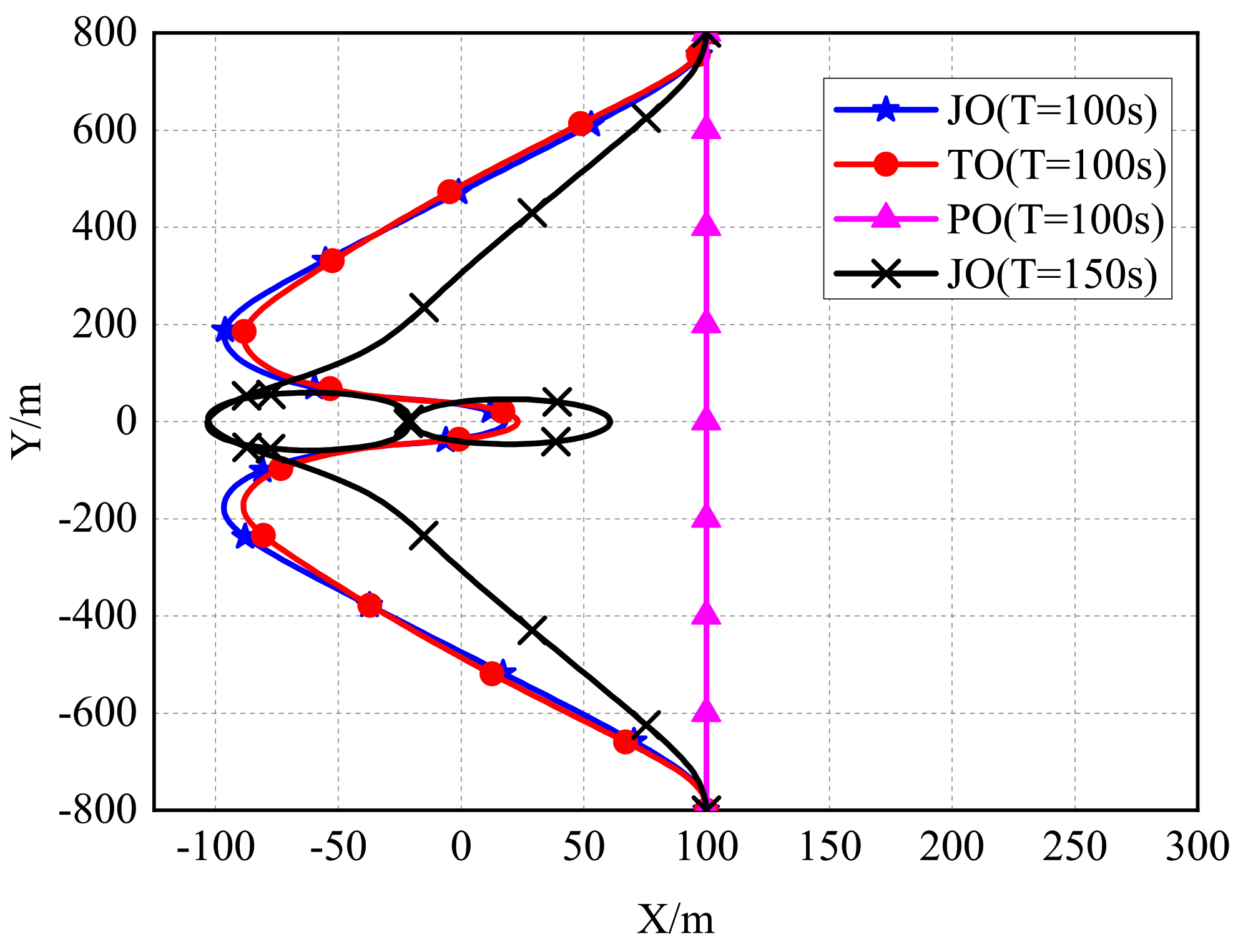
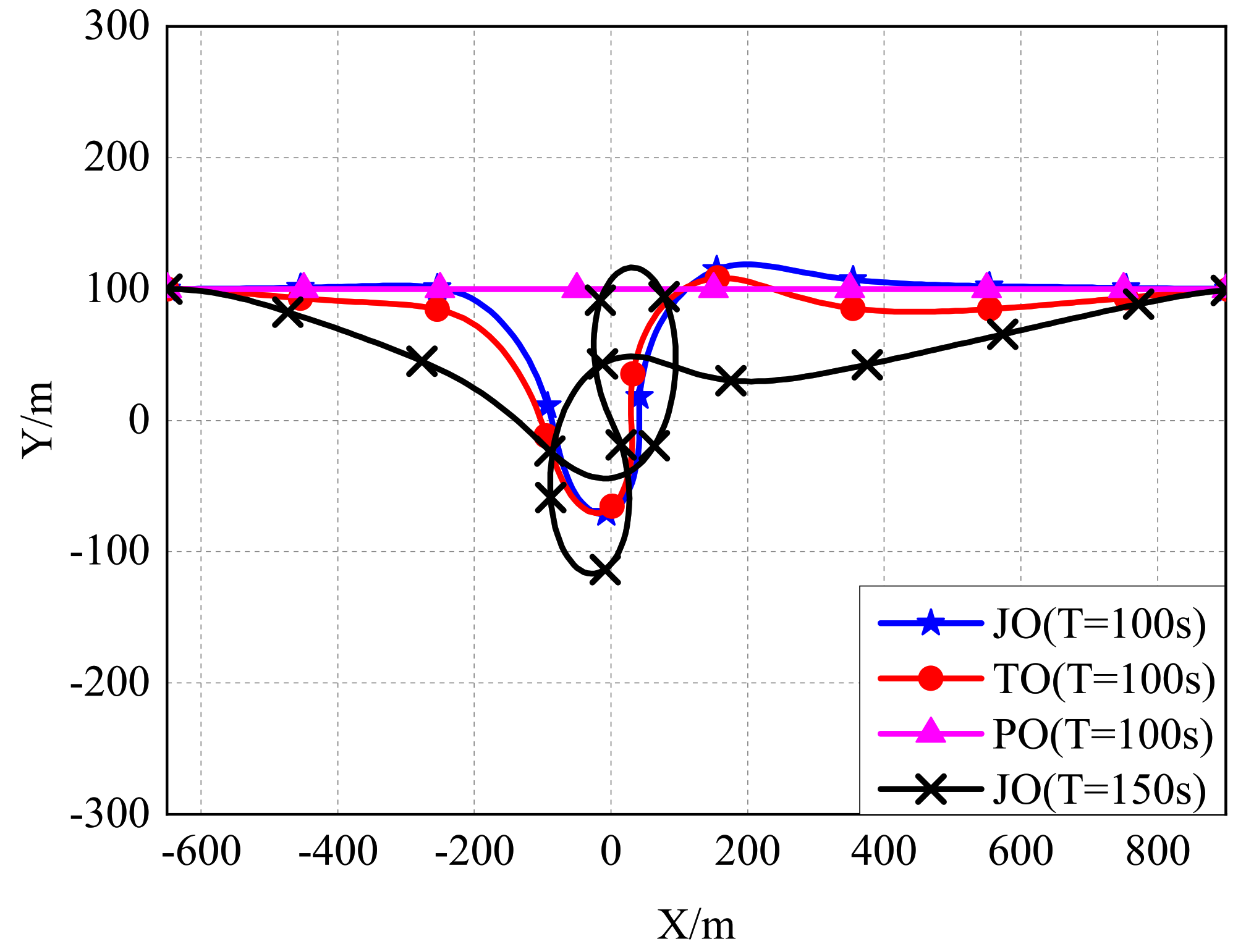
4.1.1. Trajectory Comparison of PO/JO/TO

Firstly, in order to discuss how the trajectory of the UAV influences the secure communication, we plot the obtained UAV’s trajectories on the horizontal plane of the flight height based on the different schemes in Figure 6 with the flight time T = 100 s and the UAV’s average transmit power P ¯ = 0 dBm. According to our design, the trajectory of CON is the same as that of PO; thus, the figure does not show it. Except PO, the trajectories of JO and the benchmark TO all apply trajectory optimization. Observe that with the same flight time, these optimized trajectories intend to search for the optimal balance between the ground node and the eavesdropper to obtain a higher secrecy rate. When the flight time further increases to T = 150 s, the trajectory demonstrates that the UAV cruises around the ground node as long as possible before flying to the final point, which has the proven the viewpoint.

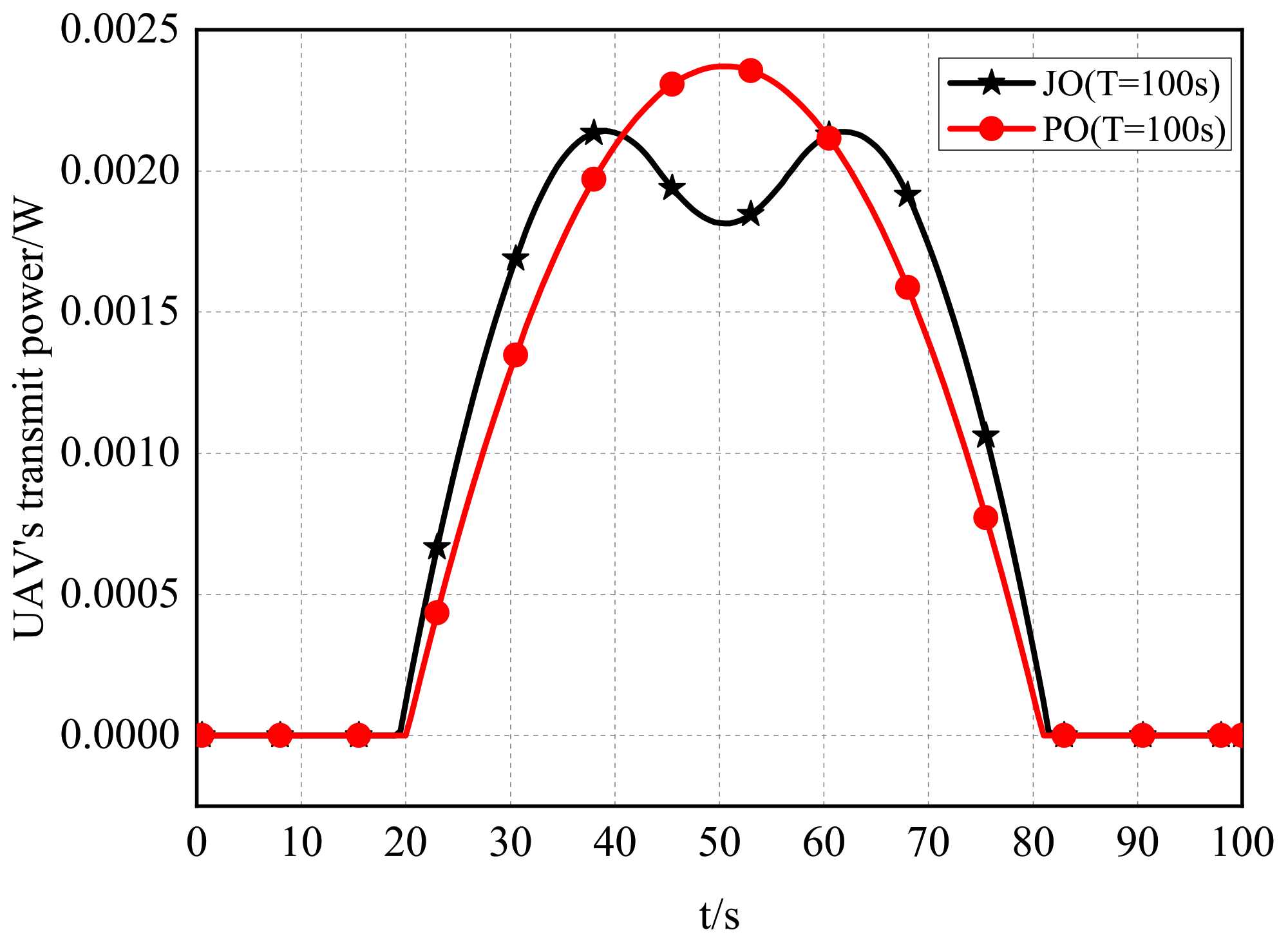
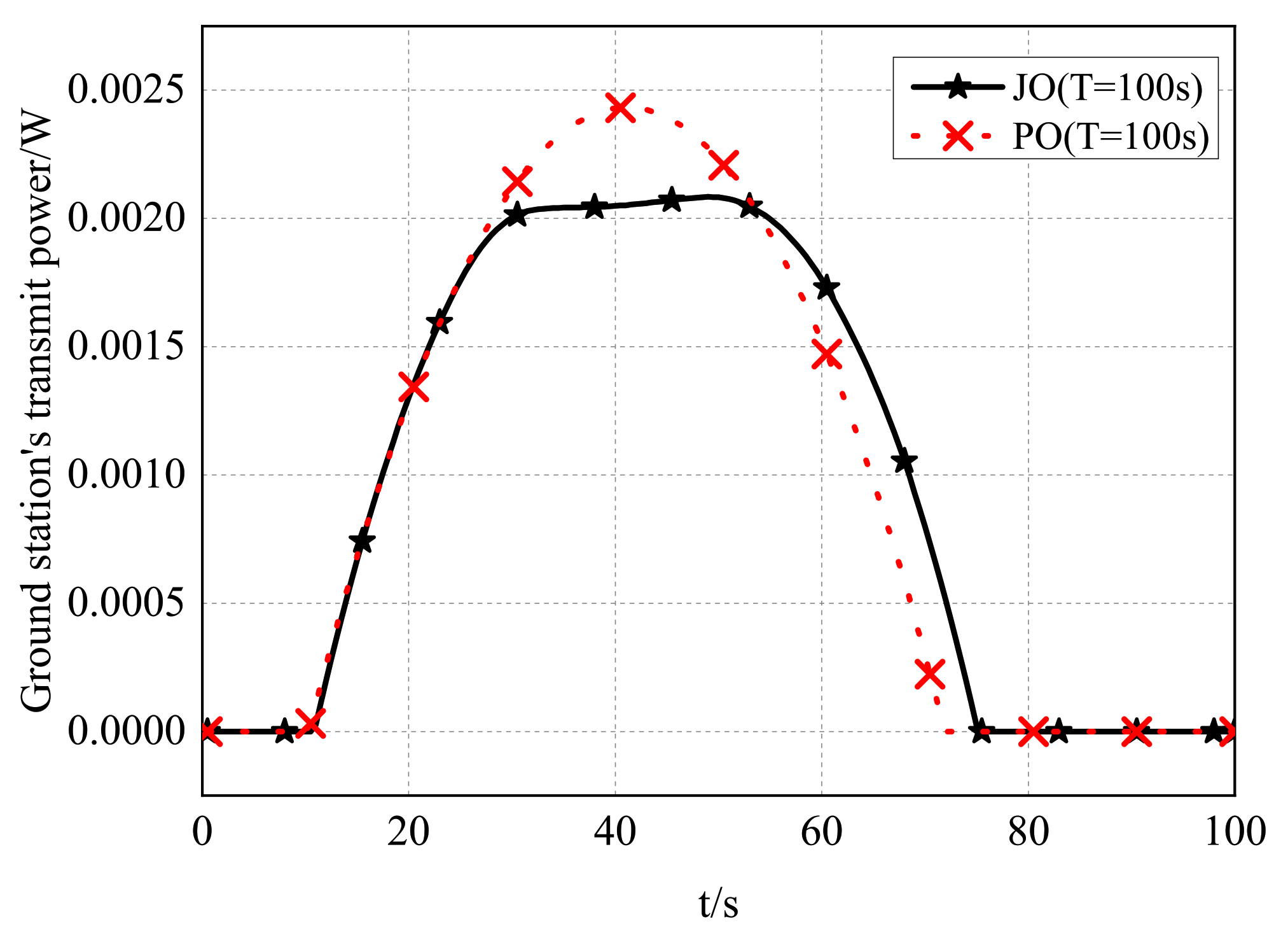
4.1.2. Comparison of the Transmit Power of PO/JO

Accordingly, considering the UAV’s transmit power is also a significant factor, the UAV’s transmit power of JO and the benchmark PO with T = 100 s and P ¯ = 0 dBm are shown in Figure 7. Explicitly, the transmit power corresponds to the trajectory, which means the transmit power is zero at the beginning and the end and increases and decreases according to the change of the position of the UAV, so as to maximize the secure EE.

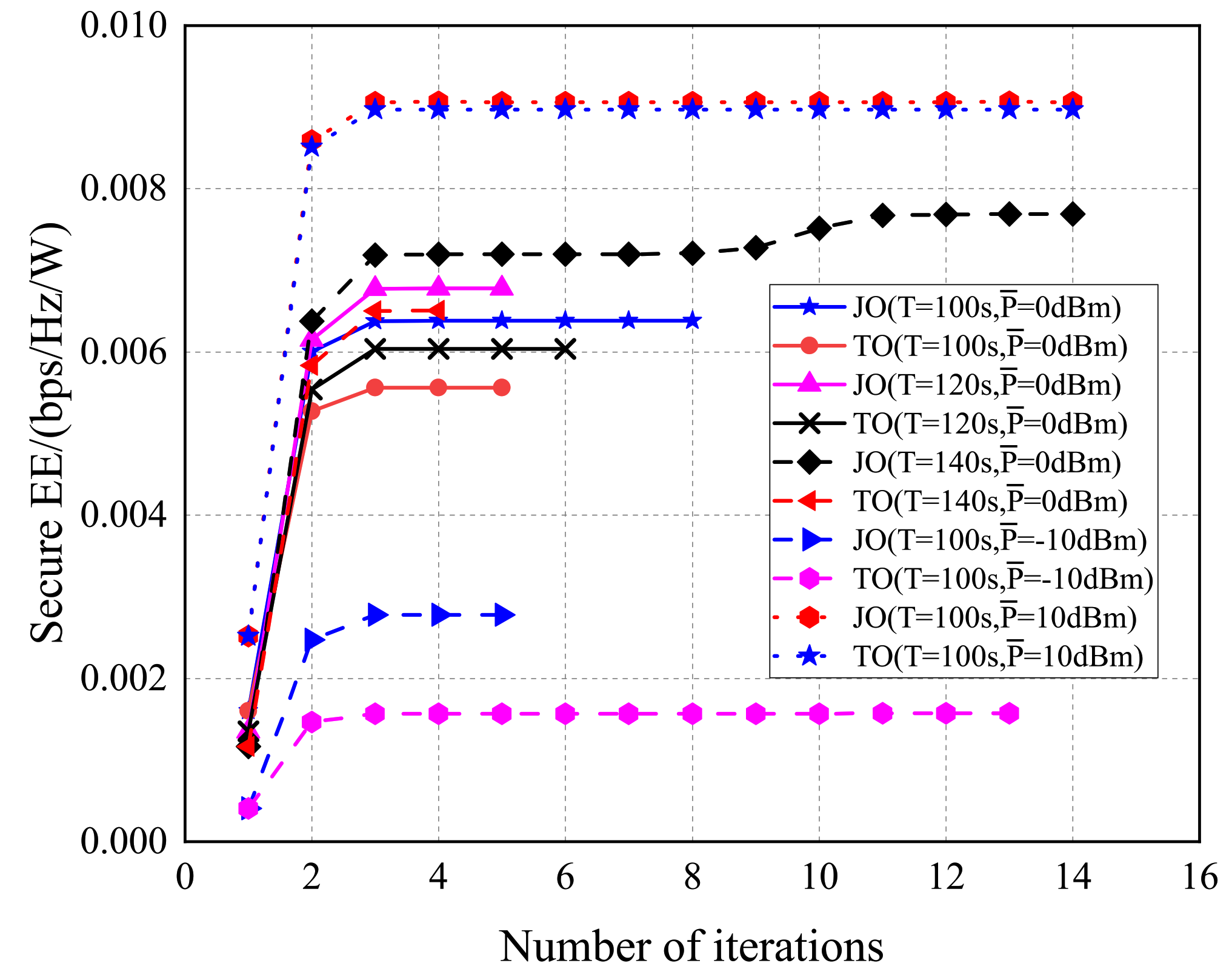
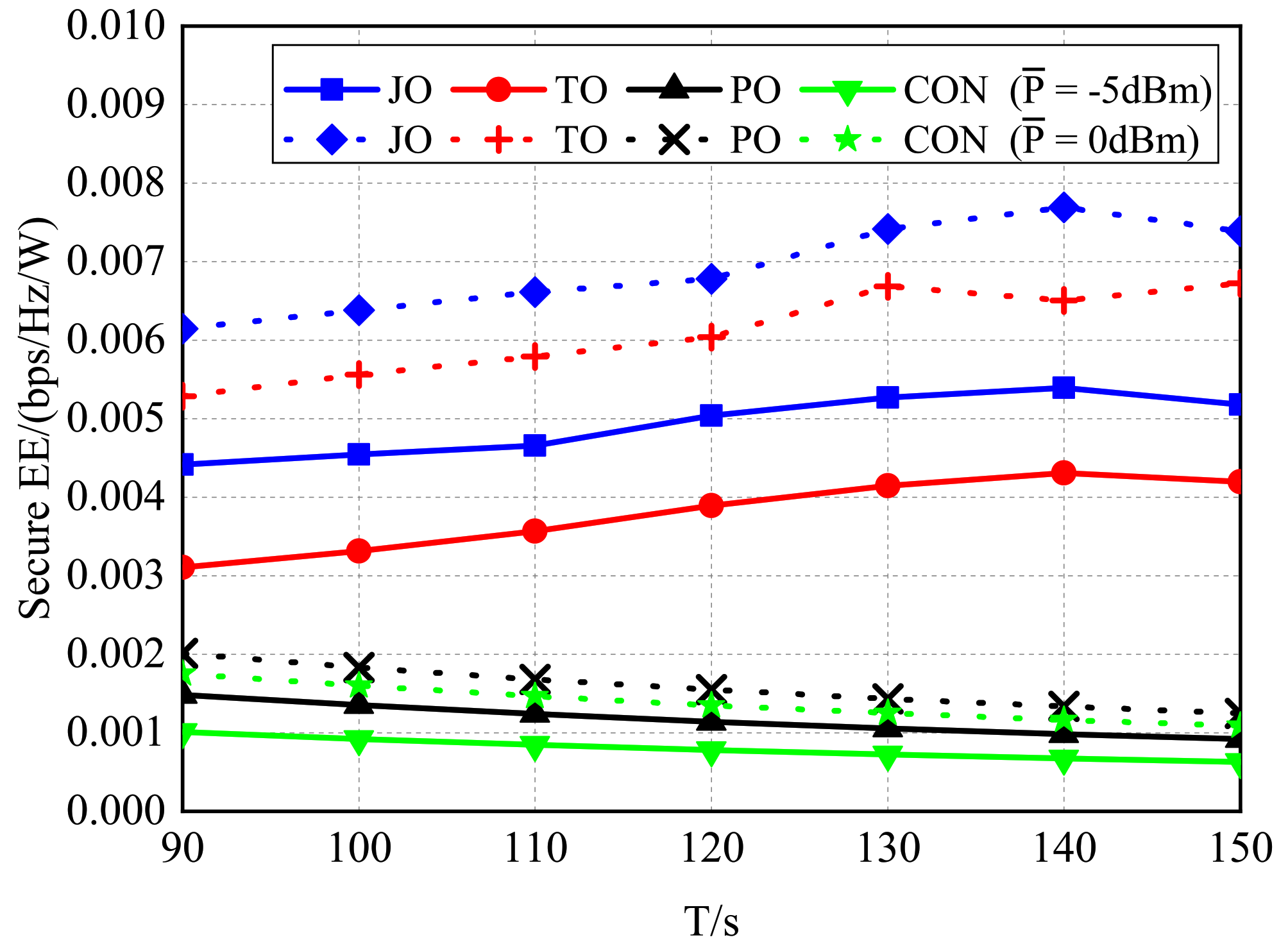
4.1.3. Comparison of the Secure EE of PO/JO/TO/CON with Various Flight Times

Next, to certify the effectiveness of JO and the relationship between the secure EE and the flight time, we present the secure EE of different algorithms with the various flight times in Figure 8. The dashed line represents the scenario with the average transmit power P ¯ = 0 dBm, and the continuous line represents the scenario with P ¯ = −5 dBm.
It was observed that with the same average transmit power, the proposed JO algorithm always obtained the maximal secure EE, while the benchmark TO was the second, followed by the PO scheme, and finally, CON obtained the lowest secure EE, as expected.
Furthermore, along with the increase of the flight time T, the secure EE of JO and TO firstly increased then began to fluctuate. In contrast, the secure EE of PO and CON decreased all the time. This is reasonable, since the trajectories of JO and TO were optimized, and the UAV was able to cruise for a longer time in the place, where it achieved a higher secrecy rate by enhancing the legitimate channel and weakening the eavesdropping channel, to neutralize the increase of energy consumption. However, due to the further trajectory requiring more energy cost, the secure EE will fluctuate when the flight time T is sufficiently large, as the improvement of the secrecy rate does not enable balancing the additional energy consumption. Additionally, for the PO and CON schemes, the obtained secrecy rates were constant, while the UAV’s energy consumption increased with the improvement of flight time T to overcome air resistance. As a result, the secure EE of these two algorithms decreased with the increase of T.

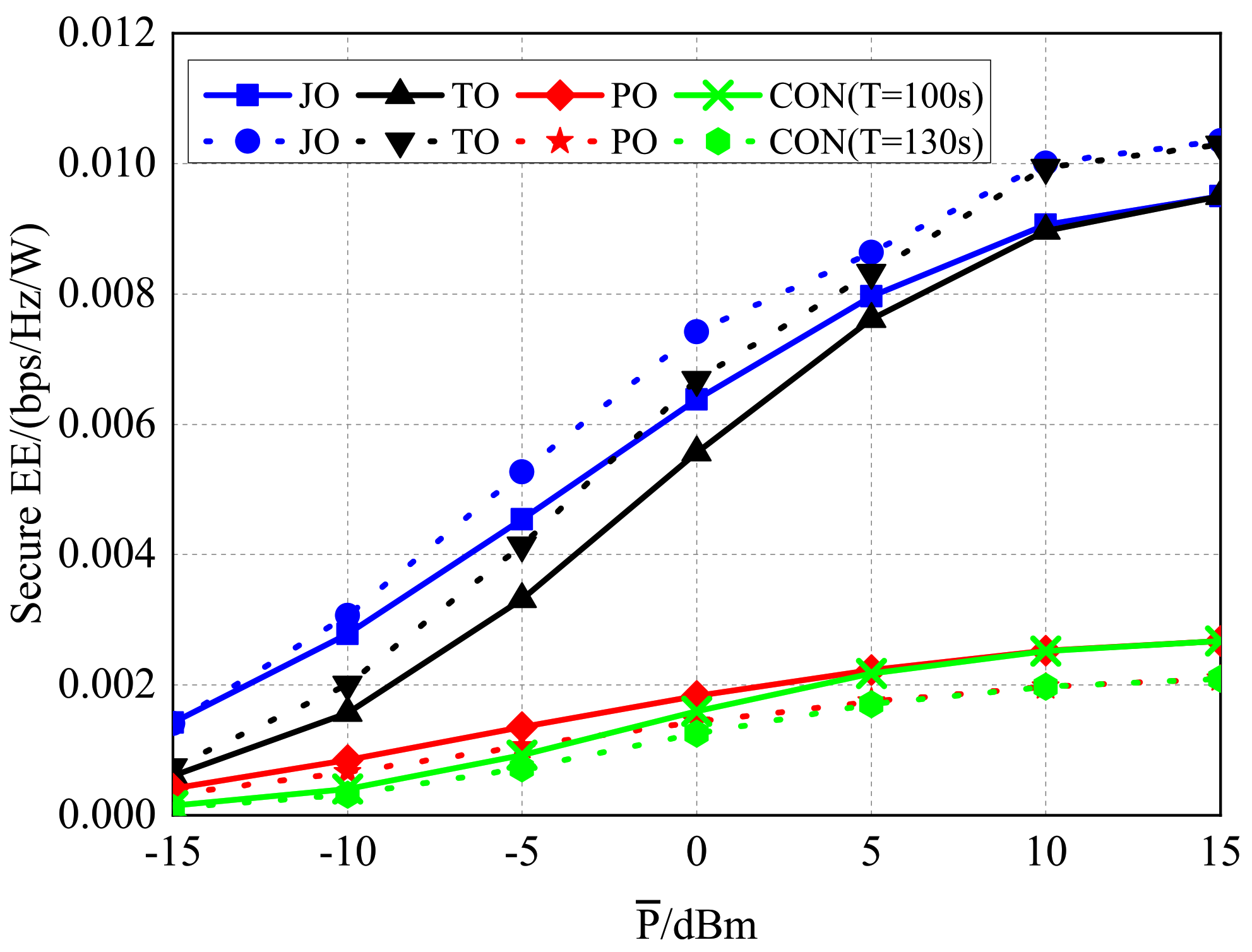
4.1.4. Comparison of the Secure EE of PO/JO/TO/CON with Different Average Transmit Powers

In order to investigate the influence of the average transmit power P ¯ on the secure EE, we plot the secure EE of these schemes with the different average transmit power in Figure 9. Explicitly, the secure EE of all schemes increased with the improvement of the average transmit power P ¯ , but the increasing trends gradually slowed down. In addition, along with the improvement of P ¯ , the secure EE of PO with T = 130 s exceeded that of CON with T = 100 s first, while the latter also obtained a higher secure EE when P ¯ ≥ 0 dBm. Meanwhile, the gap between the secure EE of JO with T = 130 s and that of TO with T = 100 s gradually decreased. The two phenomena indicated that the efficiency of power optimization weakened along with the increase of the average transmit power.

4.2. Uplink Performance of PO/JO/TO/CON

In this section, by setting 30 as the maximum allowed number of iterations J, Figure 10 proves the fast convergence of both the JO and TO schemes with different flight times or average transmit power, which verified that we can apply our proposed algorithm and the benchmarks in the scopes of the simulation parameter settings.

4.2.1. Trajectories of PO/JO/TO

In regard to the uplink communication, we intended to study the same problems, including the influence of the trajectory, the instantaneous transmit power, the flight time, and the ground node’s average transmit power. Moreover, our proposed algorithm was efficient or not. Figure 11 shows the horizontal trajectories of the UAV at the flight height generated by the different algorithms with Q ¯ = 0 dBm. It was observed that due to the trajectory optimization, JO and TO came close to the ground station firstly, then flew to the final point directly. In particular, when the flight time increased from T = 100 s to T = 150 s, JO cruised around the ground node for more time to achieve the secure EE gain, then flew directly to the final point to meet the constraints of the UAV’s trajectory and mobility.

4.2.2. Transmit Powers of PO/JO

Then, the instantaneous transmit powers of JO and the benchmark PO with the flight time T = 100 s are shown in Figure 12, which had the same trend. As the trajectories of JO and PO all came close to the ground station firstly, then went away to reach the final point, their transmit powers corresponded to their trajectories. Compared with the benchmark PO, the proposed JO had a longer time when the transmit power was not zero. This is because the UAV in the JO scheme cruised around the ground node for a longer time.

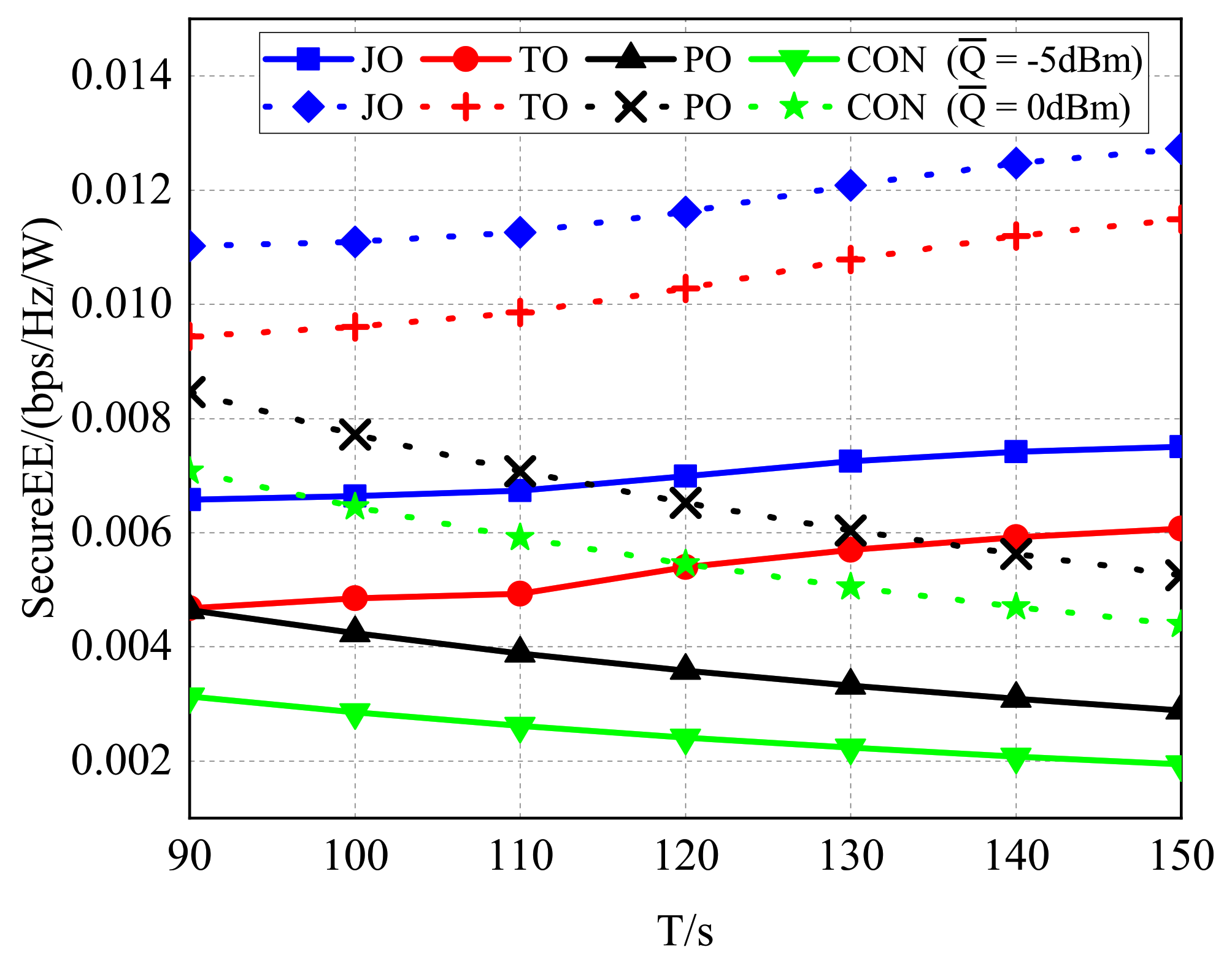
4.2.3. Comparison of the Secure EE of PO/JO/TO/CON with Various Flight Times

Next, Figure 13 and Figure 14 respectively compare the secure EE performances of diverse schemes versus T and Q ¯ . Specifically, the dashed line represents Q ¯ = 0 dBm and the continuous line represents Q ¯ = −5 dBm in Figure 13, while the dashed line represents T = 130 s and the continuous line represents T = 100 s in Figure 14. With the same Q ¯ , the proposed JO always achieved the maximal secure EE, while the benchmark CON obtained the minimum, as expected.
By observing Figure 13, we can discover that with the increase of T, the secure EE of both JO and TO gradually increased. In contrast, the secure EE of PO and CON still decreased all the time. Of particular note, with the flight time increasing, the gap between the secure EE of JO and that of TO and the gap between the secure EE of PO and that of CON gradually decreased. This proved that the effect of power optimization decreased with the improvement of the energy consumption.
Figure 13. Secure EE with different flight times T in uplink.
Aerospace 09 00050 g013
Figure 14. Secure EE with different average transmit powers Q ¯ in uplink.
Aerospace 09 00050 g014

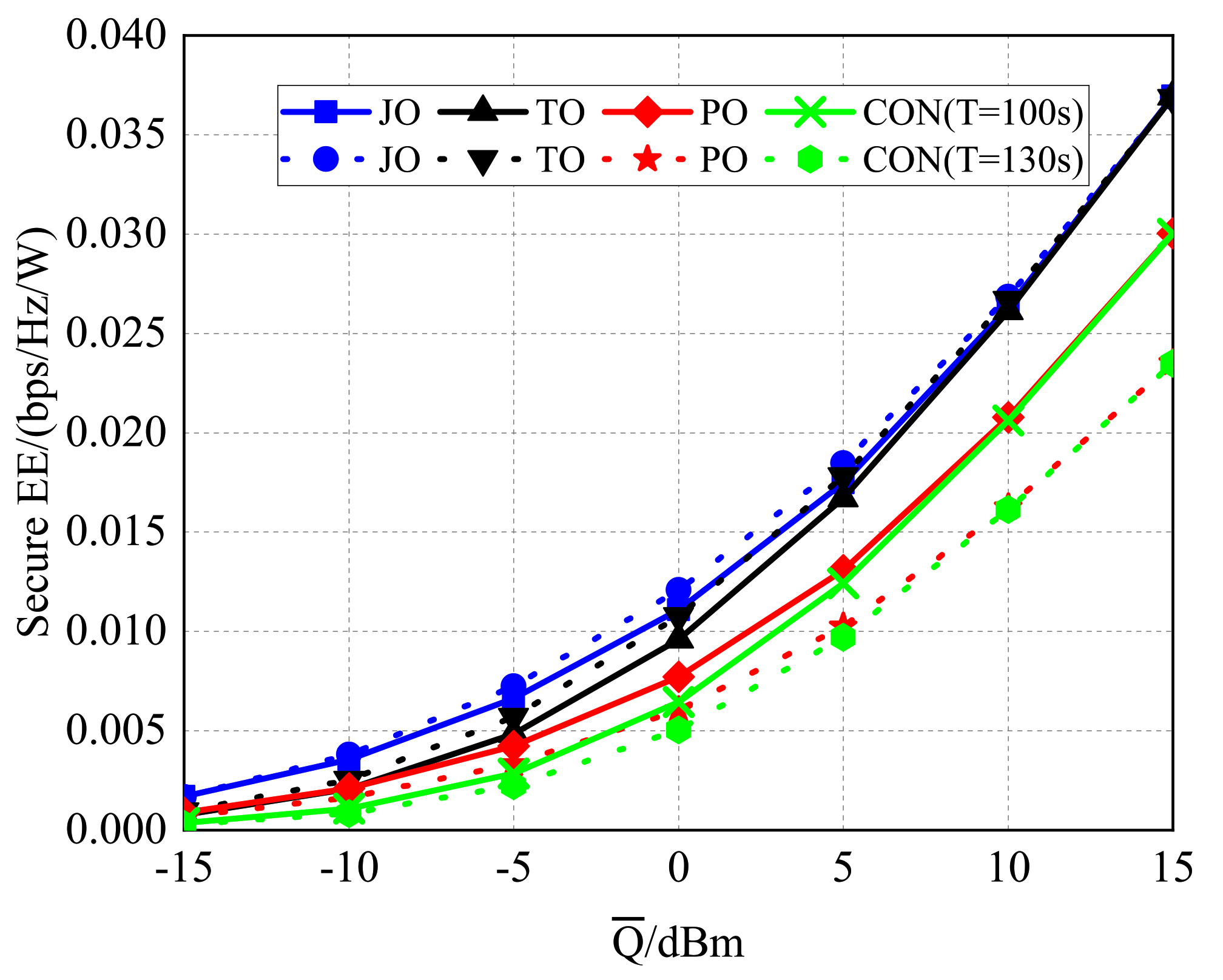
4.2.4. Comparison of the Secure EE of PO/JO/TO/CON with Different Average Transmit Powers

Furthermore, the secure EE of different algorithms with the various average transmit powers is plotted in Figure 14. With the increase of Q ¯ , all the secure EE increased evidently. Additionally, the secure EE of PO with T = 130 s exceeded that of CON with T = 100 s firstly, while the latter also obtained a higher secure EE when Q ¯ 0 dBm. Meanwhile, the secure EE of JO with T = 130 s exceeded that of TO with T = 100 s firstly, while the latter also obtained higher secure EE when Q ¯ 10 dBm, which demonstrated that the influence of power optimization weakened with the increase of the average transmit power.

5. Conclusions

This paper proposed a secure communication scheme assisted by UAVs, which jointly optimizes the transmit powers, the secure EE, and the trajectory planning. The optimization problem was formulated as maximizing both the uplink/downlink secure EE, for which the difficulty lied in the high coupling and non-convexity. To solve such a problem, we designed a two-step scheme: (1) introducing fractional programming and the alternate optimization to divide the original optimization problem into two optimization subproblems; (2) in the two subproblems, the bisection method and the interior-point method were applied to optimize the source’s transmit power and the UAV’s trajectory. Through numerical simulation and performance analysis, the following conclusions can be obtained:
(1)
As for the original non-convex problems, the design scheme was feasible to solve both the downlink and uplink problems effectively, which could obtain the optimal solution quickly;
(2)
The proposed scheme achieved a higher secure EE, with a downlink channel increase of at least 12% and at least 13% in the uplink channels when T = 120 s and P ¯ = 0 dBm, which were several times better than the worst benchmarks;
(3)
In downlink, the secure EE of the proposed scheme increased with the increase of the flight time and average transmit power, which converged to a stable value. However, in uplink, the secure EE also grew with the increase of the flight time and average transmit power, while it increased rapidly with the improvement of the average transmit power;
(4)
The overall computational complexity of the proposed algorithm was affected by the convergence threshold and the maximum allowed iterative number of each subalgorithm, as well as the number of time slots. Considering the low complexity of the interior-point method and the bisection method, the overall computational complexity was comparatively low.
As for future research, the information exchange between multiple UAVs and multiple ground nodes is worth investigating, which needs system allocation to satisfy the communication requirement while minimizing the sum of the costs.

Author Contributions

Conceptualization, Y.Y. and D.W.; methodology, Z.Y. and D.W.; software, Z.Y., D.W. and Y.Y.; validation, Z.Y.; formal analysis, Z.Y.; investigation, Z.Y.; resources, Z.Y. and X.M.; data curation, Z.Y.; writing—original draft preparation, Z.Y., Y.Y. and D.W.; writing—review and editing, Z.Y., Y.Y. and D.W.; visualization, Z.Y. and Y.Y.; supervision, X.M.; project administration, Y.Y.; funding acquisition, Y.Y., D.W. and X.M. All authors have read and agreed to the published version of the manuscript.

Funding

This research was funded by the National Natural Science Foundation of China under Grants 61901448, 61871401, and 12002340.

Institutional Review Board Statement

Not applicable.

Informed Consent Statement

Not applicable.

Data Availability Statement

Not applicable.

Conflicts of Interest

The authors declare no conflict of interest.

References

  1. Hu, Y.; Yang, Y.; Ma, X.; Li, S. Computational optimal launching control for balloon-borne solar-powered unmanned aerial vehicles in near-space. Sci. Prog. 2019, 103, 36850419877755. [Google Scholar] [CrossRef] [PubMed]
  2. Foust, J. SpaceX’s space-Internet woes: Despite technical glitches, the company plans to launch the first of nearly 12,000 satellites in 2019. IEEE Spectr. 2019, 56, 50–51. [Google Scholar] [CrossRef]
  3. Wang, X.; Yang, Y.; Wang, D.; Zhang, Z. Mission-oriented cooperative 3d path planning for modular solar-powered aircraft with energy optimization. Chin. J. Aeronaut. 2021. [Google Scholar] [CrossRef]
  4. Zhu, X.; Guo, Z.; Hou, Z. Solar-powered airplanes: A historical perspective and future challenges. Prog. Aerosp. Sci. 2014, 71, 36–53. [Google Scholar] [CrossRef]
  5. Zeng, Y.; Zhang, R. Energy-efficient UAV communication with trajectory optimization. IEEE Trans. Wirel. Commun. 2017, 16, 3747–3760. [Google Scholar] [CrossRef] [Green Version]
  6. Zeng, Y.; Zhang, R.; Lim, T.J. Wireless communications with unmanned aerial vehicles: Opportunities and challenges. IEEE Commun. Mag. 2016, 54, 36–42. [Google Scholar] [CrossRef] [Green Version]
  7. Gu, J.; Wang, H.; Ding, G.; Xu, Y.; Xue, Z.; Zhou, H. Energy-Constrained Completion Time Minimization in UAV-Enabled Internet of Things. IEEE Internet Things J. 2020, 7, 5491–5503. [Google Scholar] [CrossRef]
  8. Yuan, Z.; Yang, Y.; Hu, Y.; Ma, X. Channel-Aware Potential Field Trajectory Planning for Solar-Powered Relay UAV in Near-Space. IEEE Access 2020, 8, 143950–143961. [Google Scholar] [CrossRef]
  9. Cai, Y.; Wei, Z.; Li, R.; Ng, D.W.K.; Yuan, J. Energy-Efficient Resource Allocation for Secure UAV Communication Systems. In Proceedings of the 2019 IEEE Wireless Communications and Networking Conference (WCNC), Marrakesh, Morocco, 15–18 April 2019; pp. 1–8. [Google Scholar]
  10. Yang, G.; Dai, R.; Liang, Y.-C. Energy-efficient uav backscatter communication with joint trajectory design and resource optimization. IEEE Trans. Wirel. Commun. 2020, 20, 926–941. [Google Scholar] [CrossRef]
  11. Yang, N.; Wang, L.; Geraci, G.; Elkashlan, M.; Yuan, J.; Renzo, M.D. Safeguarding 5g wireless communication networks using physical-layer security. IEEE Commun. Mag. 2015, 53, 20–27. [Google Scholar] [CrossRef]
  12. Liang, Y.; Poor H., V.; Shamai, S. Secure communication over fading channels. IEEE Trans. Inf. Theory 2008, 54, 2470–2492. [Google Scholar] [CrossRef] [Green Version]
  13. Wang, D.; Bai, B.; Chen, W.; Han, Z. Secure green communication via untrusted two-way relaying: A physical layer approach. IEEE Trans. Commun. 2016, 64, 1861–1874. [Google Scholar] [CrossRef]
  14. Zhu, Y.; Zheng, G.; Fitch, M. Secrecy Rate Analysis of UAV-Enabled mmWave Networks Using Matérn Hardcore Point Processes. IEEE J. Sel. Areas Commun. 2018, 36, 1397–1409. [Google Scholar] [CrossRef] [Green Version]
  15. Cai, Y.; Wei, Z.; Li, R.; Ng, D.W.K.; Yuan, J. Joint trajectory and resource allocation design for energy-efficient secure uav communication systems. IEEE Trans. Commun. 2020, 68, 4536–4553. [Google Scholar] [CrossRef] [Green Version]
  16. Hua, M.; Wang, Y.; Wu, Q.; Dai, H.; Huang, Y.; Yang, L. Energy-Efficient Cooperative Secure Transmission in Multi-UAV-Enabled Wireless Networks. IEEE Trans. Veh. Technol. 2019, 68, 7761–7775. [Google Scholar] [CrossRef] [Green Version]
  17. Xiao, L.; Xu, Y.; Yang, D.; Zeng, Y. Secrecy energy efficiency maximization for uav-enabled mobile relaying. IEEE TGCN 2019, 4, 180–193. [Google Scholar] [CrossRef] [Green Version]
  18. Shakoor, S.; Kaleem, Z.; Do, D.-T.; Dobre, O.A.; Jamalipour, A. Joint optimization of UAV 3D placement and path loss factor for energy efficient maximal coverage. IEEE IoT J. 2021, 8, 9776–9786. [Google Scholar]
  19. Zhang, G.; Wu, Q.; Cui, M.; Zhang, R. Securing UAV communications via joint trajectory and power control. IEEE Trans. Wirel. Commun. 2019, 18, 1376–1389. [Google Scholar] [CrossRef] [Green Version]
  20. Dinkelbach, W. On nonlinear fractional programming. Manag. Sci. 1967, 13, 492–498. [Google Scholar] [CrossRef]
  21. Schaible, S. Fractional programming. II, on Dinkelbach’s algorithm. Manag. Sci. 1976, 22, 868–873. [Google Scholar] [CrossRef]
  22. Bezdek, J.C.; Hathaway, R.J. Some notes on alternating optimization. In Proceedings of the 2002 AFSS International Conference on Fuzzy Systems, Calcutta, India, 3–6 February 2002; pp. 288–300. [Google Scholar]
  23. Gopala, P.K.; Lai, L.; Gamal, H.E. On the secrecy capacity of fading channels. IEEE Trans. Inf. Theory 2008, 54, 4687–4698. [Google Scholar] [CrossRef] [Green Version]
  24. Wang, D.; Bai, B.; Zhao, W.; Han, Z. A survey of optimization approaches for wireless physical-layer security. IEEE Commun. Surv. Tutor. 2018, 21, 1878–1911. [Google Scholar] [CrossRef] [Green Version]
  25. Boyd, S.; Vandenberghe, L. Convex Optimization; Cambridge University Press: New York, NY, USA, 2004; pp. 561–630. [Google Scholar]
Figure 1. Three-dimensional communication network (high-altitude large-range communication and low-altitude high-density communication).
Aerospace 09 00050 g001
Figure 2. Urban low-altitude intelligent communication network and information security threat.
Aerospace 09 00050 g002
Figure 3. System’s three-dimensional (3D) model and its horizontal projection.
Aerospace 09 00050 g003
Figure 4. Flowchart of the overall proposed algorithm.
Aerospace 09 00050 g004
Figure 5. Energy efficiency versus the number of iterations in downlink.
Aerospace 09 00050 g005
Figure 6. UAV trajectories of the different schemes in downlink.
Aerospace 09 00050 g006
Figure 7. UAV transmit power of the different schemes with T = 100 s.
Aerospace 09 00050 g007
Figure 8. Secure EE with different flight times T in downlink.
Aerospace 09 00050 g008
Figure 9. Secure EE with different average transmit powers P ¯ in downlink.
Aerospace 09 00050 g009
Figure 10. Energy efficiency versus the number of iterations in uplink.
Aerospace 09 00050 g010
Figure 11. UAV trajectories of the different schemes in uplink.
Aerospace 09 00050 g011
Figure 12. Ground node transmit power of the different schemes with T = 100 s.
Aerospace 09 00050 g012
Table 1. Scheme descriptions.
NamesDescriptionsParameters
JOOur proposed schemeCalculated
TOTrajectory optimization with given powerChoose P ¯ as the given power
POPower optimization with a given trajectoryChoose v 0 as the constant velocity
CONGiven power and trajectoryChoose P ¯ and v 0
Table 2. Simulation parameter settings.
Parameter DefinitionNotationsValue
Common Parameter Settings
The height the UAV flies atH100 m
The coordinates of R s r s r ( 0 , 0 )
The coordinates of E s e s e ( 300 , 0 )
Time slot δ t 0.5 s
Maximum velocity v m a x v m a x = 20 m/s
Maximum acceleration a m a x a m a x = 2 m/s 2
Channel gain β 0 50 dB
Noise power σ 2 100 dBm
Energy consumption parameters c 1 c 1 = 9.26 × 10 4
c 2 c 2 = 2250
Convergence threshold ε , ζ ε = 10 5 , ζ = 10 5
Specific Parameter Settings for Downlink Communication
The UAV’s initial and final positions s 0 , s f s 0 ( 100 , 800 ) , s f ( 100 , 800 )
Maximum UAV’s transmit power P m a x P m a x = 4 P ¯
Average UAV’s transmit power P ¯ P ¯ = 15 , 10 , 5 , 0 , 5 , 10 , 15 dBm
Flight timeT T = 90 , 100 , 110 , 120 , 130 , 140 , 150 s
The UAV’s initial and final velocities v 0 , v f v 0 = v f = ( s f s 0 ) / T
Specific Parameter Settings for Uplink Communication
The UAV’s initial and final positions s 0 , s f s 0 = ( 650 , 100 ) , s f = ( 950 , 100 )
Maximum UAV’s transmit power Q m a x Q m a x = 4 Q ¯
Average UAV’s transmit power Q ¯ Q ¯ = 15 , 10 , 5 , 0 , 5 , 10 , 15 dBm
Flight timeT T = 90 , 100 , 110 , 120 , 130 , 140 , 150 s
The UAV’s initial and final velocities v 0 , v f v 0 = v f = ( s f s 0 ) / T
Publisher’s Note: MDPI stays neutral with regard to jurisdictional claims in published maps and institutional affiliations.

