
Reverse Design of a Novel Coupling Strut for Vibration Attenuation in the Helicopter Cabin

Abstract
:1. Introduction
2. Dynamic Model and Analysis Method
2.1. Governing Equation for Longitudinal Wave Propagation
2.1.1. Rod without Resonators
2.1.2. Rod with Resonators
2.2. Propagation Constant of the Infinite Periodic Strut
2.3. Vibration Transmission of the Finite Strut
- (1)
- Free-Free Condition
- (2)
- Fix-Fix Condition
3. Simulation Analysis and Results Discussion
3.1. Illustrative Example
3.2. Parametric Influence Study
3.3. Reverse Design
4. Conclusions
- (1)
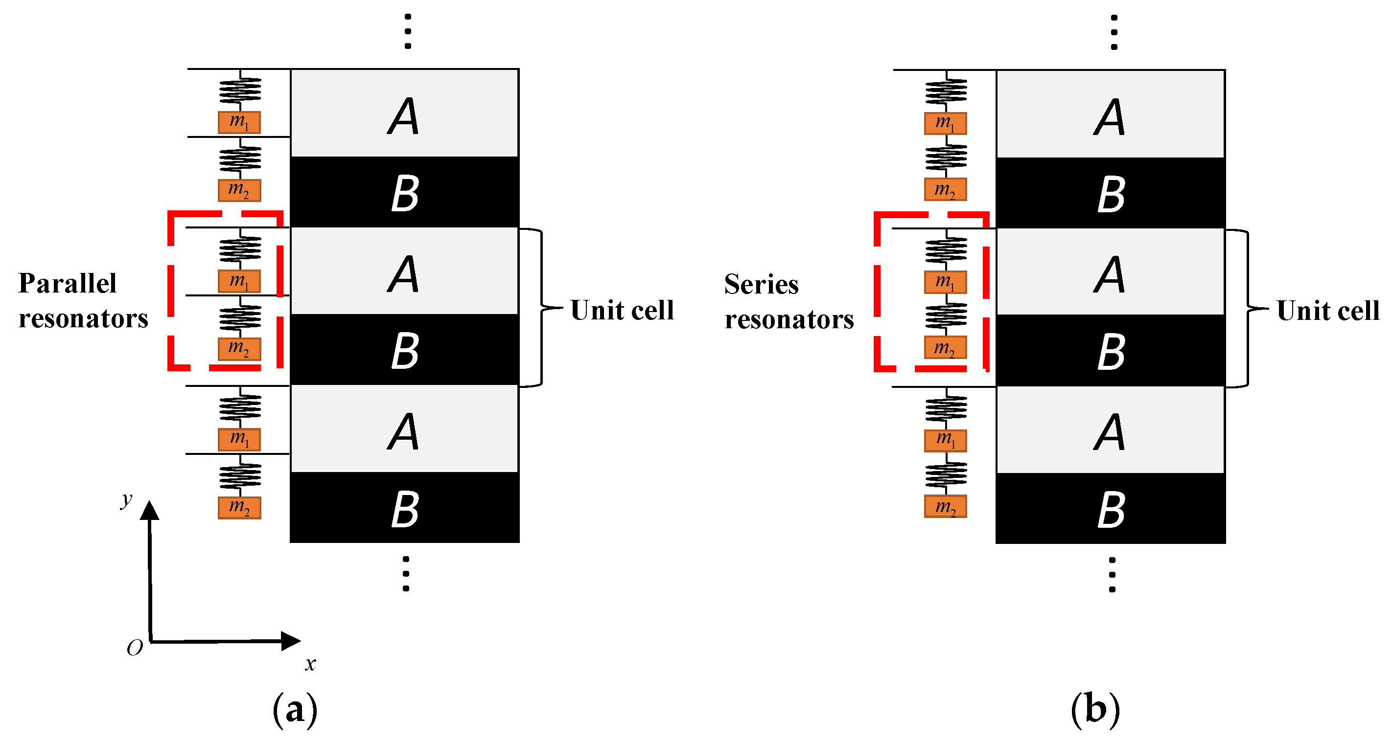
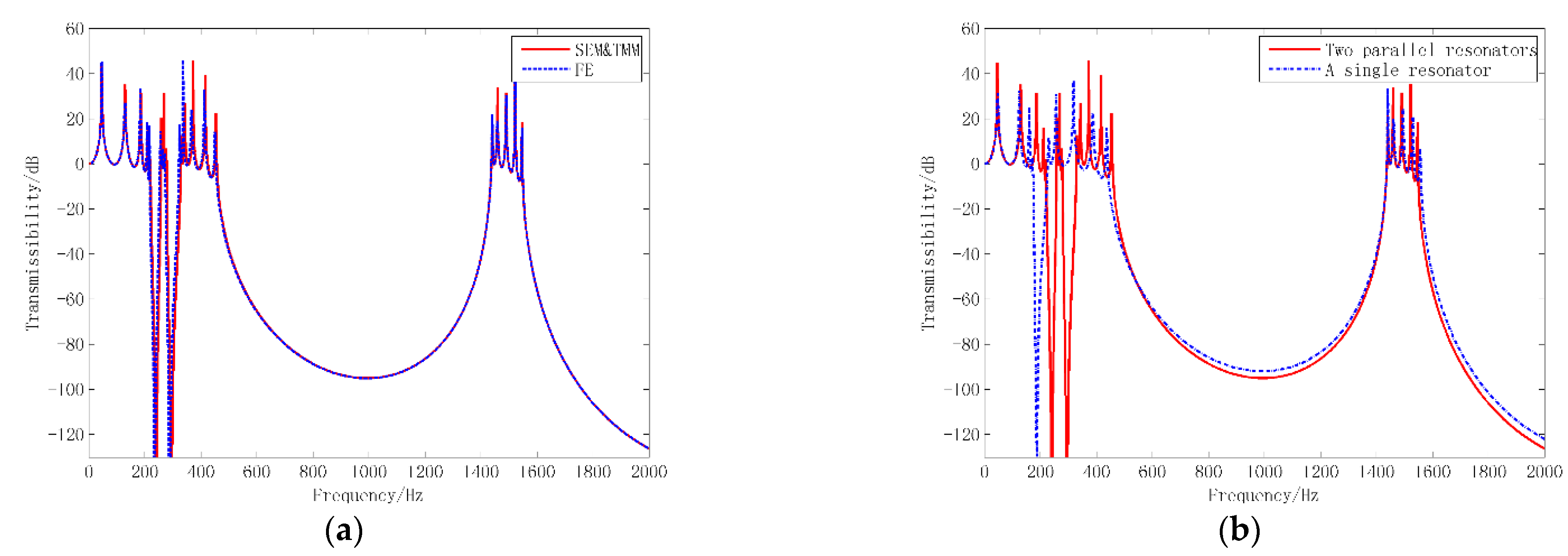
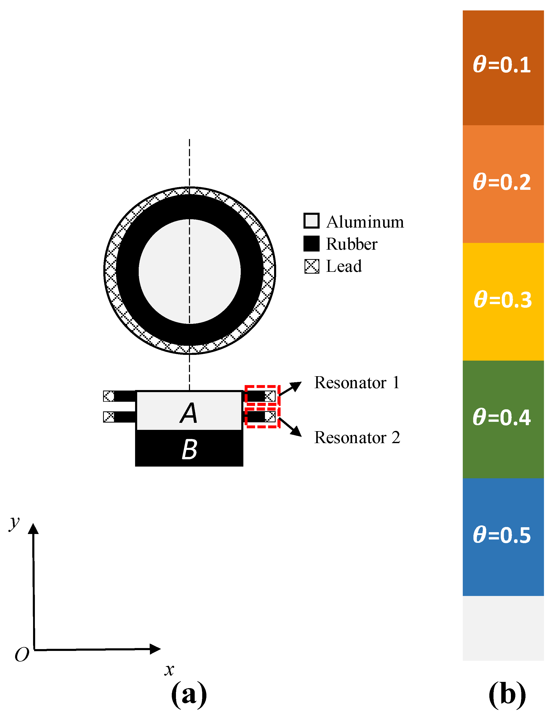
- When the total mass of lead of the resonators remains the same, the parallel two resonators can generate more band gaps, which has advantages in multi-bandgap design.
- (2)
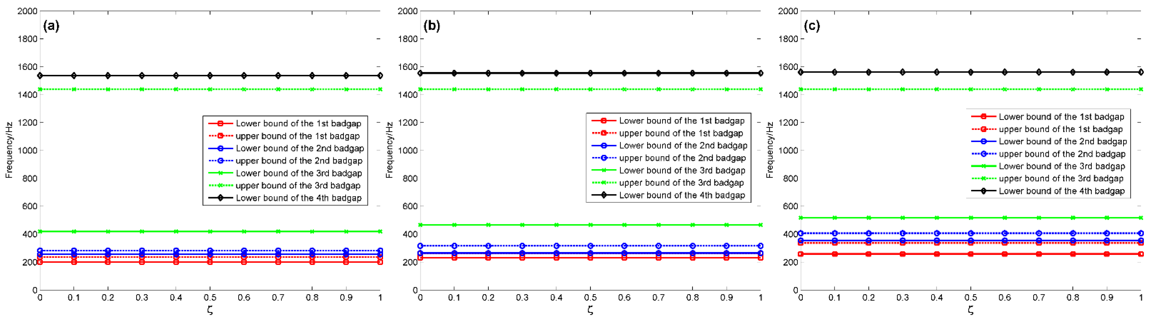
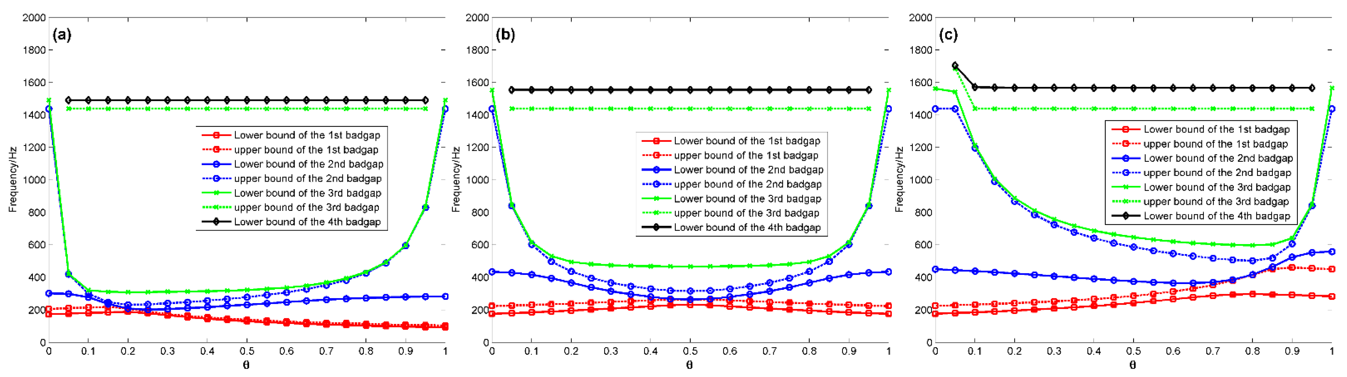
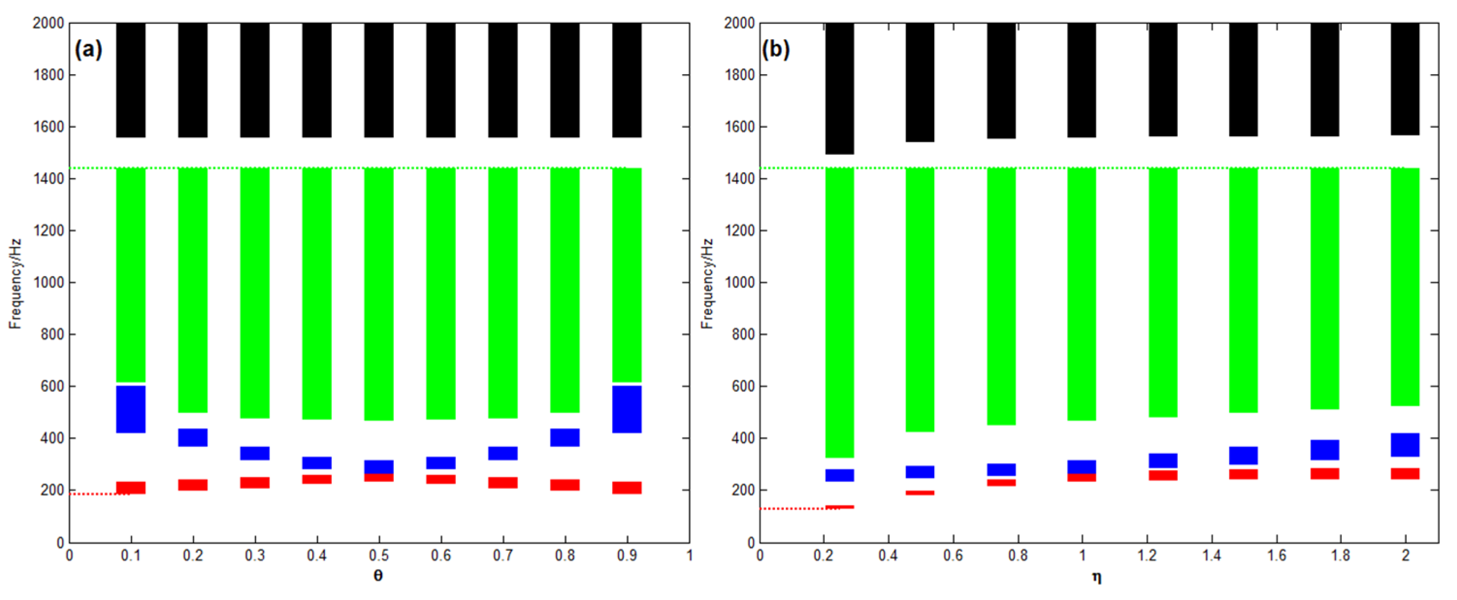
- Under ideal infinite periodic conditions, the coupling mechanism between the LR and Bragg band gaps can be achieved by setting graded mass ratio .
- (3)
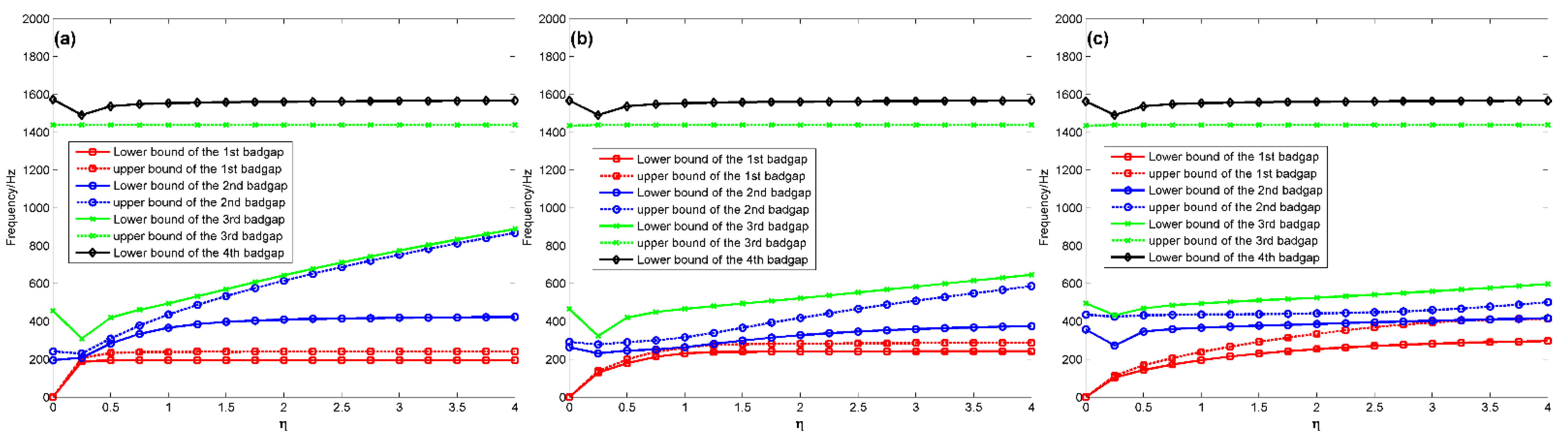
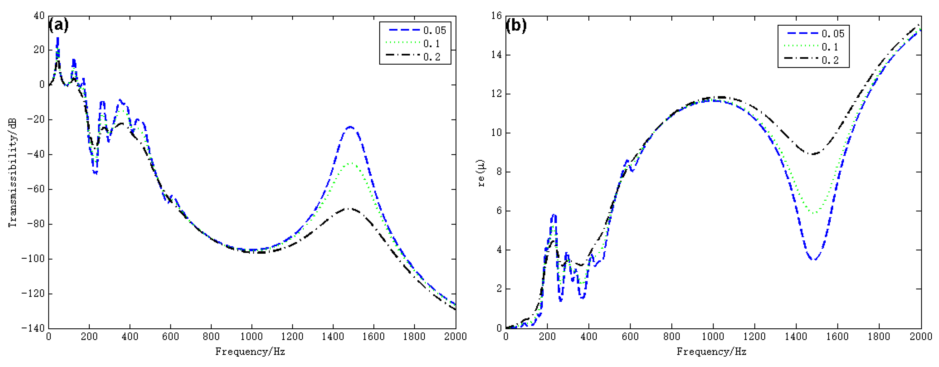
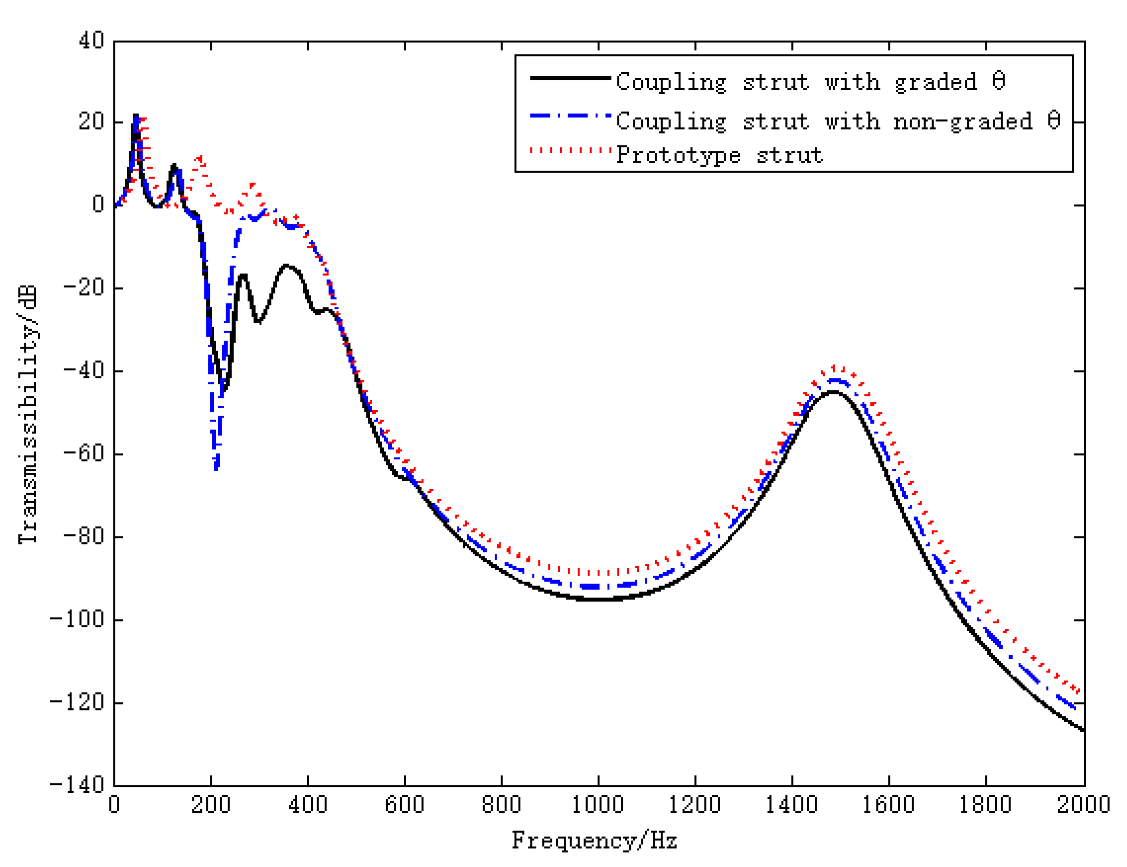
- The coupling strut with graded widens the width of bandgap of the prototype strut by 155 Hz in the low frequency direction when the loss factor set to be 0.1.
- (4)
- When the loss factor set to be 0.1, the proposed strut has better performance on vibration attenuation than the prototype one in the range of 152 Hz to 500 Hz, with a max improvement reaching 43.25 dB at 226 Hz.
- (5)
- In the case of , the proposed strut has a significant advantage on the vibration attenuation within 500–2000 Hz. The vibration transmissibility of the proposed strut decreases by up to 8.9 dB over the prototype strut at 2000 Hz.
- (6)
- For the coupling strut proposed in this paper, only the main constraints (e.g., simple boundary conditions, length and mass) are considered to provide the basic ideas and procedures of the design and optimization. The proposed design scheme can be easily extended to manage more complex situations as well. In future works, with an eye on practical implementation, many other constraints should be included, such as strength, stiffness, fatigue life, and so on.
Author Contributions
Funding
Institutional Review Board Statement
Informed Consent Statement
Data Availability Statement
Conflicts of Interest
References
- Simon, F.; Haase, T.; Unruh, O.; Pohl, M.; Tijs, E.; Wijntjes, R.; Van Der Wal, H.; Ghiringhelli, G.L. Activities of european research laboratories regarding helicopter internal noise. Aerosp. Lab. 2014, 7, 1–14. [Google Scholar]
- Cheng, L.; Xia, Y. Review of civil aircraft cabin noise standards and control method. Sci. Technol. Vis. 2015, 27, 130. [Google Scholar]
- Pasco, Y.; Berry, A.; Grewal, A.; Chapleau, S.L. Active control of transmission noise in a Bell 407 helicopter. In Proceedings of the 70th Annual Forum of the American Helicopter Society, Montreal, QC, Canada, 20–22 May 2014; American Helicopter Society: Fairfax, VA, USA, 2014; pp. 174–182. [Google Scholar]
- Millott, T.A.; Yoerkie, C.A.; Welsh, W.A.; MacMartin, D.G.; Davis, M.W. Flight test of active gear-mesh noise control on the S-76 aircraft. In Proceedings of the Annual Forum Proceedings-American Helicopter Society, Washington, DC, USA, 20–22 May 1998; American Helicopter Society: Fairfax, VA, USA, 1998; pp. 241–250. [Google Scholar]
- Sutton, T.J.; Elliot, S.J.; Brennan, M.J.; Heron, K.H.; Jessop, D.A.C. Active Isolation of Multiple Structural Waves on a Helicopter Gearbox Support Strut. J. Sound Vib. 1997, 205, 81–101. [Google Scholar] [CrossRef]
- Maier, R.; Hoffmann, F.; Tewes, S.; Bebesel, M. Active Vibration Isolation System for Helicopter Interior Noise Reduction. In Proceedings of the 8th AIAA/CEAS Aeroacoustics Conference & Exhibit, Breckenridge, CO, USA, 17–19 June 2002; p. 2495. [Google Scholar]
- Ma, X.J.; Lu, Y.; Wang, F.J. Active Structural Acoustic Control of Helicopter Interior Multifrequency Noise Using Input-Output-Based Hybrid Control. J. Sound Vib. 2017, 405, 187–207. [Google Scholar] [CrossRef]
- He, C.; Zhang, F.; Jiang, J.H. Adaptive Boundary Control of Flexible Manipulators with Parameter Uncertainty Based on RBF Neural Network. Shock Vib. 2020, 6, 1–13. [Google Scholar] [CrossRef]
- Petitjean, B.; Legrain, I.; Simon, F.; Pauzin, S. Active Control Experiments for Acoustic Radiation Reduction of a Sandwich Panel: Feedback and Feedforward Investigations. J. Sound Vib. 2002, 252, 19–36. [Google Scholar] [CrossRef]
- Lepage, A.; Mortain, F.; Coste, L. Active Structural Acoustic Control of a Helicopter Trim Panel. In Proceedings of the Internoise 2005, the Institute of Noise Control Engineering, Rio de Janeiro, Brazil, 7–10 August 2005. [Google Scholar]
- Flanneley, W.G. The Dynamic Antiresonant Vibration Isolator. In Proceedings of the American Helicopter Society 22th Annual Forum, Washington, DC, USA, 11–13 May 1966; pp. 152–160. [Google Scholar]
- Braun, D. Vibration Isolator. U.S. Patent 4,619,349, 28 October 1986. [Google Scholar]
- Peter, K. Recent Advances in Eurocopter’s Passive and Active Vibration Control. In Proceedings of the American Helicopter Society 64th Annual Forum, Montréal, QC, Canada, 29 April–1 May 2008. [Google Scholar]
- Halwes, D.R. LIVE–Liquid Inertia Vibration Eliminator. In Proceedings of the American Helicopter Society 36th Annual Forum, Washington, DC, USA, 13–14 May 1980. [Google Scholar]
- He, C.; Lim, K.M.; Zhang, F.; Jiang, J.H. Dual-tuning mechanism for elastic wave transmission in a triatomic lattice with string stiffening. Wave Motion 2022, 112, 102951. [Google Scholar] [CrossRef]
- Yadav, A.; Gerislioglu, B.; Ahmadivand, A.; Kaushik, A.; Cheng, G.J.; Ouyang, Z.; Wang, Q.; Yadav, V.S.; Mishra, Y.K.; Wu, Y.; et al. Controlled self-assembly of plasmon-based photonic nanocrystals for high performance photonic technologies. Nano Today 2021, 37, 101072. [Google Scholar] [CrossRef]
- Asiri, S.; Baz, A.; Pines, D. Periodic Struts for Gearbox Support System. J. Vib. Control 2005, 11, 709–721. [Google Scholar] [CrossRef]
- Singh, A.; Pines, D.; Baz, A. Active/Passive Reduction of Vibration of Periodic One-Dimensional Structures Using Piezoelectric Actuators. Smart Mater. Struct. 2004, 13, 698–711. [Google Scholar] [CrossRef]
- Asiri, S.; Baz, A.; Pines, D. Active Periodic Struts for a Gearbox Support System. Smart Mater. Struct. 2006, 15, 1707–1714. [Google Scholar] [CrossRef]
- Szefi, J.T. Helicopter Gearbox Isolation Using Periodically Layered Fluidic Isolators. Ph.D. Dissertation, Mechanical and Nuclear Engineering Department, Pennsylvania State University, University Park, PA, USA, 2003. [Google Scholar]
- Szefi, J.T.; Smith, E.C.; Lesieutre, G.A. Formulation and Validation of a Ritz-Based Analytical Model for Design of Periodically-Layered Isolators in Compression. In Proceedings of the 19th AIAA Applied Aerodynamics Conference, Washington, DC, USA, 11–14 April 2001; p. 1684. [Google Scholar]
- Szefi, J.T.; Smith, E.C.; Lesieutre, G.A. Formulation and Validation of a Ritz-Based Analytical Model of High-Frequency Periodically Layered Isolators in Compression. J. Sound Vib. 2003, 268, 85–101. [Google Scholar] [CrossRef]
- Szefi, J.T.; Smith, E.C.; Lesieutre, G.A. Design and Analysis of High-Frequency Periodically Layered Isolators for Helicopter Gearbox Isolation. In Proceedings of the 44th AIAA/ASME/ASCE/AHS/ASC Structures, Structural Dynamics, and Materials Conference, Norfolk, VA, USA, 7–10 April 2003; p. 1784. [Google Scholar]
- Szefi, J.T.; Smith, E.C.; Lesieutre, G.A. Design and Testing of a Compact Layered Isolator for High-Frequency Helicopter Gearbox Isolation. In Proceedings of the 45th AIAA/ASME/ASCE/AHS/ASC Structures, Structural Dynamics & Materials Conference, Palm Springs, CA, USA, 19–22 April 2004; p. 1947. [Google Scholar]
- Wang, F.; Torbati, M.M.; Ma, X.; Lu, Y. Design of near-periodic struts for helicopter gearbox vibration isolation using multicell optimization. AIAA J. 2019, 57, 2634–2647. [Google Scholar] [CrossRef]
- Wang, F.J.; Lu, Y. Research on a Gearbox Periodic Strut for Helicopter Cabin Noise Reduction. Acta Aeronaut. Astronaut. Sin. 2016, 37, 3370–3384. [Google Scholar]
- Lu, Y.; Wang, F.J.; Ma, X.J. Research on the Vibration Characteristics of a Compounded Periodic Strut Used for Helicopter Cabin Noise Reduction. Shock Vib. 2017, 2017, 1–12. [Google Scholar] [CrossRef] [Green Version]
- Lu, Y.; Wang, F.J.; Ma, X.J. Helicopter Interior Noise Reduction Using Compounded Periodic Strut. J. Sound Vib. 2018, 435, 264–280. [Google Scholar] [CrossRef]
- Liu, Z.; Zhang, X.; Mao, Y.; Zhu, Y.Y.; Yang, Z.; Chan, C.T.; Sheng, P. Locally resonant sonic materials. Science 2000, 289, 1734–1736. [Google Scholar] [CrossRef]
- Oudich, M.; Li, Y.; Assouar, B.M.; Hou, Z. A sonic band gap based on the locally resonant phononic plates with stubs. New J. Phys. 2010, 12, 083049. [Google Scholar] [CrossRef]
- Goffaux, C.; Sánchez-Dehesa, J.; Yeyati, A.L.; Lambin, P.; Khelif, A.; Vasseur, J.O.; Djafari-Rouhani, B. Evidence of fano-like interference phenomena in locally resonant materials. Phys. Rev. Lett. 2002, 88, 225502. [Google Scholar] [CrossRef] [Green Version]
- Liu, Z.; Chan, C.T.; Sheng, P. Three-component elastic wave band-gap material. Phys. Rev. 2002, 65, 165116. [Google Scholar] [CrossRef] [Green Version]
- Wang, G.; Wen, X.; Wen, J.; Shao, L.; Liu, Y. Two-dimensional locally resonant phononic crystals with binary structures. Phys. Rev. Lett. 2004, 93, 154302. [Google Scholar] [CrossRef] [PubMed]
- Wang, G.; Wen, J.; Wen, X. Quasi-one-dimensional phononic crystals studied using the improved lumped-mass method: Application to locally resonant beams with flexural wave band gap. Phys. Rev. 2005, 71, 104302. [Google Scholar] [CrossRef]
- Hsu, J.C.; Wu, T.T. Lamb waves in binary locally resonant phononic plates with two-dimensional lattices. Appl. Phys. Lett. 2007, 90, 201904. [Google Scholar] [CrossRef]
- Liang, X.; Zhang, F.; Jiang, J. Ultra-wideband outward-hierarchical metamaterials with graded design. Int. J. Mech. Mater. Des. 2022, 18, 69–184. [Google Scholar] [CrossRef]
- He, C.; Lim, K.M.; Liang, X.; Zhang, F.; Jiang, J. Tunable band structures design for elastic wave transmission in tension metamaterial chain. Eur. J. Mech. A/Solids 2022, 92, 104481. [Google Scholar] [CrossRef]
- Thompson, D.J. A continuous damped vibration absorber to reduce broad-band wave propagation in beams. J. Sound Vib. 2008, 311, 824–842. [Google Scholar] [CrossRef]
- Brennan, M.J. Characteristics of a wideband vibration neutralizer. Noise Control Eng. J. 1997, 45, 201–207. [Google Scholar] [CrossRef]
- Strasberg, M.; Feit, D. Vibration damping of large structures induced by attached small resonant structures. J. Acoust. Soc. Am. 1996, 99, 335–344. [Google Scholar] [CrossRef]
- Nishida, E.; Koopmann, G.H. A method for designing and fabricating broadband vibration absorbers for structural noise control. J. Vib. Acoust. 2007, 129, 397–405. [Google Scholar] [CrossRef]
- Carcaterra, A.; Akay, A.; Bernardini, C. Trapping of vibration energy into a set of resonators: Theory and application to aerospace structures. Mech. Syst. Signal Process. 2012, 26, 1–14. [Google Scholar] [CrossRef]
- Doyle, J.F. Wave Propagation in Structures: Spectral Analysis Using Fast Discrete Fourier Transforms. The Spectral Element Method, 2nd ed.; Springer: Berlin/Heidelberg, Germany, 1997; pp. 152–157. [Google Scholar]
- Lee, U.; Joohong, K.; Andrew, Y.L. Spectral element method in structural dynamics. Shock Vib. Dig. 2000, 23, 451–465. [Google Scholar] [CrossRef]
- Xiao, Y.; Wen, J.; Wen, X. Longitudinal wave band gaps in metamaterial-based elastic rods containing multi-degree-of-freedom resonators. New J. Phys. 2012, 14, 033042. [Google Scholar] [CrossRef]
- Jouaillec, F.; Ohayon, R. Fluid-Structure Vibration Analysis of Infinite Periodic Stiffened Cylinders. In Proceedings of the ASME/Pressure Vessels and Piping Conference, Computational Methods for Coupled Fluid-Structure Analysis, ASME, New Orleans, LA, USA, 24 June 1985; pp. 1–6. [Google Scholar]
- Wen, J.S.; Wen, J.H.; Yu, D.L.; Wang, G.; Liu, Y.Z.; Han, X.Y. Phononic Crystal; National Defense Industry Press: Beijing, China, 2009. [Google Scholar]
- Ernst, F.G. Rubber Springs Design; Newnes-Butterworths: London, UK, 1974. [Google Scholar]
- Hussein, M.I.; Hulbert, G.M.; Scott, R.A. Dispersive Elastodynamics of 1D Banded Materials and Structures: Analysis. J. Sound Vib. 2006, 289, 779–806. [Google Scholar] [CrossRef]
- Hussein, M.I.; Hamza, K.; Hulbert, G.M.; Scott, R.A.; Saitou, K. Multiobjective Evolutionary Optimization of Periodic Layered Materials for Desired Wave Dispersion Characteristics. Struct. Multidiscip. Optim. 2006, 31, 60–75. [Google Scholar] [CrossRef] [Green Version]
- Wen, J.H.; Wang, G.; Yu, D.L.; Zhao, H.G.; Liu, Y.Z.; Wen, X.S. Study on the Vibration Band Gap and Vibration Attenuation Property of Phononic Crystals. Sci. China Ser. Technol. Sci. 2008, 51, 85–99. [Google Scholar] [CrossRef]


| Materials | Density /kg·m−3 | Elastic Modulus /GPa | Shear Modulus /Gpa | |
|---|---|---|---|---|
| Parameters of the rod | Aluminum | 2700 | 73 | 28.7 |
| Rubber | 1291 | 0.0024 | 0.001 | |
| Parameters of the resonators | Rubber | 1291 | 0.0024 | 0.001 |
| Lead | 11,600 | 40.8 | 14.9 |
| Part | Material | Inner Radius /m | Outer Radius /m | Length/m |
|---|---|---|---|---|
| Rod | Aluminum | \ | 0.025 | 0.02 |
| Rubber | \ | 0.0215 | 0.015 | |
| Resonator 1 | Rubber | 0.0250 | 0.0350 | 0.005 |
| Lead | 0.0350 | 0.0371 | 0.005 | |
| Resonator 2 | Rubber | 0.0250 | 0.0350 | 0.005 |
| Lead | 0.0350 | 0.0381 | 0.005 |
| Mass /kg | Equivalent Stiffness /N·m−1 | Resonance Frequency /Hz | ||
|---|---|---|---|---|
| Parallel resonators | Resonators 1 | 0.0273 | 93,368.56 | 294.16 |
| Resonators 2 | 0.0410 | 93,368.56 | 240.18 | |
| Single resonator | 0.0683 | 93,368.56 | 186.04 | |
| Cell 1 | Cell 2 | Cell 3 | Cell 4 | Cell 5 | |
|---|---|---|---|---|---|
| Outer radius of lead of resonator1/m | 0.0395 | 0.0391 | 0.0386 | 0.0381 | 0.0376 |
| Outer radius of lead of resonator 2/m | 0.0355 | 0.0361 | 0.0366 | 0.0371 | 0.0376 |
Publisher’s Note: MDPI stays neutral with regard to jurisdictional claims in published maps and institutional affiliations. |
© 2022 by the authors. Licensee MDPI, Basel, Switzerland. This article is an open access article distributed under the terms and conditions of the Creative Commons Attribution (CC BY) license (https://creativecommons.org/licenses/by/4.0/).
Share and Cite
Ding, M.; Jiang, J.; Zhang, F.; Liang, X.; Shen, N. Reverse Design of a Novel Coupling Strut for Vibration Attenuation in the Helicopter Cabin. Aerospace 2022, 9, 843. https://doi.org/10.3390/aerospace9120843
Ding M, Jiang J, Zhang F, Liang X, Shen N. Reverse Design of a Novel Coupling Strut for Vibration Attenuation in the Helicopter Cabin. Aerospace. 2022; 9(12):843. https://doi.org/10.3390/aerospace9120843
Chicago/Turabian StyleDing, Ming, Jinhui Jiang, Fang Zhang, Xiao Liang, and Nansun Shen. 2022. "Reverse Design of a Novel Coupling Strut for Vibration Attenuation in the Helicopter Cabin" Aerospace 9, no. 12: 843. https://doi.org/10.3390/aerospace9120843