1. Introduction
According to statistics, the vast majority of major aviation fatalities in the world are Controlled Flight Into Terrain (CFIT). CFIT means that the aircraft is in a fully airworthy state prior to and at the time of collision with the ground or water, and the crash results in serious aircraft damage, injuries, or casualties [
1].
The United States took the lead in addressing CFIT by launching the Ground Proximity Warning System (GPWS) [
2], and in 1976 agreed to authorize the use of GPWS for commercial aircraft. The GPWS can provide excessive descent rate warning [
3,
4], excessive terrain closure warning [
5,
6], negative climb rate after take-off warning [
7,
8], unsafe terrain clearance warning [
9], glide slope warning [
10], and other mode alarm functions. Each mode receives various flight parameters of the aircraft as input data, and compares these parameters with a variety of internally stored warning thresholds. If any warning threshold is exceeded, audible and visual warnings are provided to the crew. The deployment of GPWS significantly improved the safety of aircraft during take-off and approach landing, and played a key role in reducing the occurrence of CFIT [
11,
12]. Furthermore, a large number of scholars have improved the warning capability of GPWS. For example, reference [
13] improved reliability by using warning judgment by weighted fusion of correction altitudes provided by multiple sensors. Reference [
14] generated the terrain clearance floor envelope enclosing the runway, and suppressed warnings within the envelope to avoid excessive nuisance warnings during landing. When different mode alarms occur at the same time, reference [
15] proposed a time-based mode switching method. GPWS is a reactive system, and only when the aircraft enters a hazardous zone will it give a warning. In order to reduce nuisance warnings, GPWS provides the pilot minimal lead time, requiring swift action to avert the hazard. A system that provides a preview of ground hazards based on the projected aircraft trajectory would allow the pilot to anticipate potential danger and plan evasive action with lower workload.
Since the beginning of the 21st century, with the rapid development of digital map technology, navigation technology, and satellite positioning technology, the Enhanced Ground Proximity Warning System (EGPWS) came into being [
16]. EGPWS is also known as the Terrain Awareness and Warning System (TAWS) [
17,
18]. EGPWS adds Forward Looking Terrain Avoidance (FLTA) and terrain display functions in addition to the original mode alert function. FLTA can provide a “look-ahead” function, which improves the pilot’s awareness of the surrounding terrain and gives the pilot more time to plan and act prior to hazard arrival. As the core function of the TAWS, FLTA has received extensive attention from researchers since it was proposed. Reference [
19] designed the FLTA envelope by establishing the normal trajectory, vertical trajectory, and inclined recovery trajectory of the helicopter. References [
20,
21] designed the vertical envelope of FLTA by establishing the aircraft’s standard vertical avoidance maneuver trajectory. Reference [
22] studied the time threshold of a forward-looking alarm, and analyzed the alarm performance under different time thresholds. Reference [
23] proposed a forward-looking warning method that uses terrain matching to correct the relative position error between helicopter and terrain. In addition, for the interference warning, reference [
24] proposed a method to adjust the FLTA envelope according to the Required Navigation Performance (RNP) of aircraft.
Although the proposed methods can provide the FLTA function for the crew, the traditional FLTA envelope adopts a trapezoidal side boundary. When the aircraft turns, it is prone to nuisance alarms, which reduces the reliability of the FLTA. To solve this problem, this paper proposes a resilient forward-looking terrain avoidance warning method. The method adjusts the beginning width of the FLTA through the navigation error and terrain resolution. During turning flight, the FLTA side boundary is modified by the roll angle to construct a resilient adjustable side boundary model, which reduces nuisance alarms and improves the reliability of the alerts.
2. Helicopter Terrain Awareness and Warning System (HTAWS)
HTAWS is to evaluate whether the aircraft will crash into the ground through the information provided by airborne sensors such as radio altitude, atmospheric data, attitude, instrument landing, and terrain/obstacle database, and generate corresponding auditory and visual signals. HTAWS comprises two functions, the mode alert and the FLTA alert. The mode alert compares the current state information of the aircraft provided by the onboard sensor to compare with combinations of states used to define hazardous operation to inform the alert logic. The mode alert includes 6 modes: excessive descent rate warning (Mode 1), excessive terrain closure warning (Mode 2), negative climb rate after take-off warning (Mode 3), unsafe terrain clearance warning (Mode 4), glide slope warning (Mode 5), and altitude call and excessive roll/pitch warning (Mode 6) [
25].
The objective of the FLTA alert is to compute a virtual three-dimensional envelope in the space of the aircraft’s forward motion based on current flight state. When alerting is enabled (for helicopters, the activation conditions include when the airspeed is greater than 21 m/s, the landing gear is retracted or the flight height is greater than 3 m, and the current altitude is greater than the calculated clipping height) [
25], the aircraft automatically obtains data information such as terrain and obstacles, and compares the spatial position relationship between the envelope and the surrounding terrain in real time. When the surrounding terrain penetrates the envelope, an alert is triggered. The schematic diagram of FLTA flight is shown in
Figure 1. The envelopes for FLTA are divided into caution envelopes and warning envelopes. The construction process of the two envelopes is identical, consisting of 4 parts, namely, the look-down boundary, the look-ahead boundary, the look-up boundary, and the side boundary. The safety margin of the warning envelope is smaller than the caution envelope’s margin [
26], and
Figure 2 shows FLTA’s implementation block diagram.
The look-down boundary is mainly determined by the aircraft’s minimum safe altitude loss ΔH. During cruise flight, ΔH is generally a fixed value. However, during take-off or landing, ΔH changes with the distance from the aircraft to the nearest runway [
26]. To avoid false alarms when the aircraft flies over the terrain at a relatively low altitude, a cut-off boundary is set. When the cut-off boundary is larger than the look-down boundary, the cut-off boundary is used as the new look-down boundary. The cut-off boundary starts from a predetermined offset position below the aircraft and extends ahead of flight at a predetermined cut-off angle. The cut-off angle calculation formula is
where
γ is the flight path angle.
θsx is the upper limit of the cut-off angle.
δb is the base value.
The look-ahead boundary is determined by the look-ahead distance and the corresponding influence coefficient. For the helicopter, the look-ahead distance is equal to the sum of the reaction distance and the distance from cruise to hover. The look-ahead distance calculation formula is
where
V is the flight speed.
g is the gravitational acceleration.
α is the nominal pitch angle for hovering.
T is the reaction time of the pilot.
The look-up boundary is determined by the altitude loss, look-up distance, and look-up extended angle. The look-up distance is equal to the look-ahead distance multiplied by various coefficients. To avoid hazardous terrain, the aircraft must pull up and. Alerts are computed using Equation (3), where altitude loss is defined as the vertical distance flown from maneuver initiation to the start of the climb.
where
dHc represents the loss altitude of the caution alert and
dHw represents the loss altitude of the warning alert.
Vz is the vertical speed.
a is the acceleration during the pull-up maneuver.
The side boundary is defined by the beginning width
Bw, the centerline deflection angle
θ, and the side deviation angle
δ, as shown in
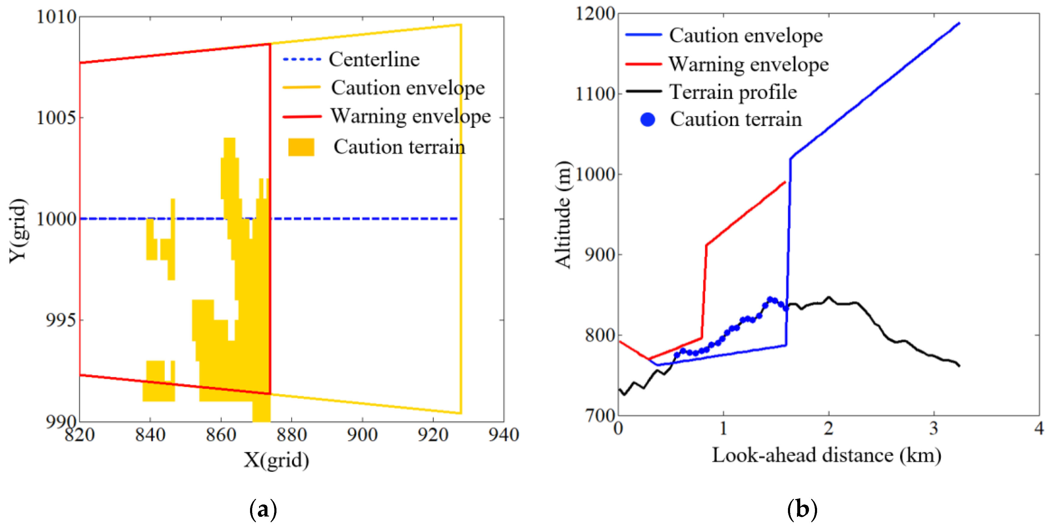
Figure 3. The centerline of the side boundary starts from the current position of the aircraft and extends to both sides with a fixed deviation angle to form a trapezoidal side boundary. The trapezoidal boundary provides the best prediction of hazardous terrain during rectilinear flight (i.e., the radius of turn is infinite). As the radius of turn decreases, less of the aircraft’s projected trajectory will lie within the trapezoidal boundary, increasing the likelihood of a mismatch between anticipated and actual terrain height. When the aircraft turns, the accuracy of terrain awareness will be reduced.
Construction of the trapezoidal boundary and the extraction of terrain data within the boundary consists of the following 5 steps.
(1) Using the current position (
c0,
r0) of the aircraft, calculate the row and column coordinates of the four endpoints of the trapezoidal boundary on the digital terrain elevation map as
where
DLA is the look-ahead distance and
k3 is the coefficient of the caution look-up distance.
(2) Construct a polygonal database from vertex coordinates. Store the maximum ordinate Rmax, starting abscissa Cmax, and reciprocal of slope k corresponding to each line segment.
(3) Arrange the coordinate data of the sampling points stored in (2) in ascending order. Using the scan line method, the terrain between the line segments is retrieved and stored.
(4) For each terrain data element retrieved, calculate the distance dl from the beginning width Bw. Arrange dl in ascending order, and partition the retrieved terrain data according to the set distance threshold.
(5) For the forward-looking alert, an alert is issued as long as there is a large terrain penetration boundary. Therefore, the maximum value of each row in the split terrain data is compared with the envelope to realize a forward-looking alert judgment.
FLTA enhances the flight crew’s perception of the surrounding terrain and facilitates less abrupt maneuvering due to earlier planning. When the aircraft turns, the traditional trapezoidal boundary centerline increasingly deviates from the real flight trajectory along the centerline distance. In
Figure 3, the red hazardous terrain not in front of the flight will lead to a false alarm and the yellow hazardous terrain in front of the real flight will cause a missing alarm. These interference alarms will affect the normal flight of the crew and reduce the reliability of the FLTA alert.
3. Resilient Forward-Looking Terrain Avoidance Warning Method (RFLTA)
The resilient forward-looking terrain avoidance warning method retains the look-down boundary, the look-ahead boundary, and the look-up boundary of the traditional method, and modifies the horizontal boundary. The method combines the current map resolution and 3 times the real-time estimation error of the navigation system to construct the beginning width. The forward-looking alert envelope is adjusted according to the aircraft roll angle. When the aircraft is flying in a straight line, the trapezoidal side boundary is used to extract the terrain data within the envelope, and when the aircraft is turning, the terrain data are extracted using the pipe-shaped side boundary shown in
Figure 4, where the square represents the terrain grid, the green squares represent terrain elevation extracted from the side boundary, and the red and yellow squares represent the hazardous terrain.
Construction of the pipe-shaped boundary and the extraction of terrain data within the boundary are described in the following 7 steps.
(1) Using the real-time estimation error
σxy provided by the aircraft navigation system and the resolution
res of the map data used by the aircraft, adjust the beginning width
Bw of the boundary as
(2) Using the current position of the aircraft (
c0,
r0), speed
V, attitude, and other information, calculate the radius
R of the pipe-shaped boundary, the coordinates of the center of the circle (
xo,
yo), the center angle α, and the coordinates of the baseline endpoints (
cs,
rs), (
ce,
re).
where
φ is the aircraft roll angle.
θ is the angle between the centerline and the east.
(3) Set the sampling number S. Sample the equal central angle of the pipe-shaped boundary to obtain the coordinates of the sampling point on the arc. Take the endpoint of the baseline as the fixed point, expand the sampling point according to the set deviation angle δ, and obtain the coordinates of the sampling point after the deviation.
Set a fixed number of samples
NS, and take (
cs,
rs) and (
ce,
re) as the starting points (
ca,
ra), respectively, to sample along the arc with equal center angle. The sampling coordinate on the arc is (
ci,
ri). Expand (
ci,
ri) with the set deviation angle
δ, and calculate the sampling coordinate on the pipe-shaped boundary as follows.
where
i represents the
i-th sampling point.
(4) Connect each sampling point end to end to construct an approximate pipeline-shaped polygon. A polygonal database is constructed to store the maximum ordinate Rmax, the initial abscissa Cmax, and the reciprocal of the slope k corresponding to each line segment.
(5) Arrange the coordinate data of the sampling points stored in (2) in ascending order. Using the scan line method, the terrain between the line segments is retrieved and stored.
(6) For each terrain data element retrieved, calculate the distance dl from the starting width Bw and the distance LR from the center of the circle and compute the corresponding central angle α and arc length LM. Arrange LM in ascending order, and split the retrieved terrain data according to the set distance threshold.
(7) For the forward-looking alert, an alert is issued when terrain penetrates the boundary. The maximum value of each row in the partitioned terrain data is compared with the envelope to realize a forward-looking alert judgment.
4. Experimental Results and Analysis
The resilient forward-looking terrain avoidance warning method is tested and verified using real terrain elevation data and simulated flight. The size of the digital terrain elevation map used in the experiment is 540 km × 540 km, and the map resolution is 30 m. The terrain contour map and the three-dimensional simulated flight trajectory are shown in
Figure 5 and
Figure 6, respectively. The initial height of the simulated flight trajectory is 518.16 m and the initial speed is 25.72 m/s. The width of the safety corridor generated by the navigation and positioning error is 90 m. The flight status data are updated at 50 Hz.
The RFLTA caution and warning alert tests are carried out for rectilinear and curvilinear flight, respectively. The roll angle, forward-looking distance (DLA), radio altitude, and remaining impact time are counted as shown in
Table 1. The RFLTA caution alert and warning alert results are shown in
Figure 7 and
Figure 8.
As can be seen from
Figure 7 and
Figure 8, when the hazardous terrain ahead of the flight penetrates the caution envelope, the system issues the alert "Caution Terrain". When the hazardous terrain ahead of the flight penetrates the warning envelope, the system issues the alert "Warning Terrain". Aside from the mode alert, when the alert occurs, the method computes the remaining impact time based on the current flight state parameters for the flight crew’s reference. As shown in
Table 1, for the caution alert shown in
Figure 7, the remaining time for the aircraft to hit the nearest hazardous terrain is 10.46 s. For the warning alert shown in
Figure 8, the time to impact is 5.86 s.
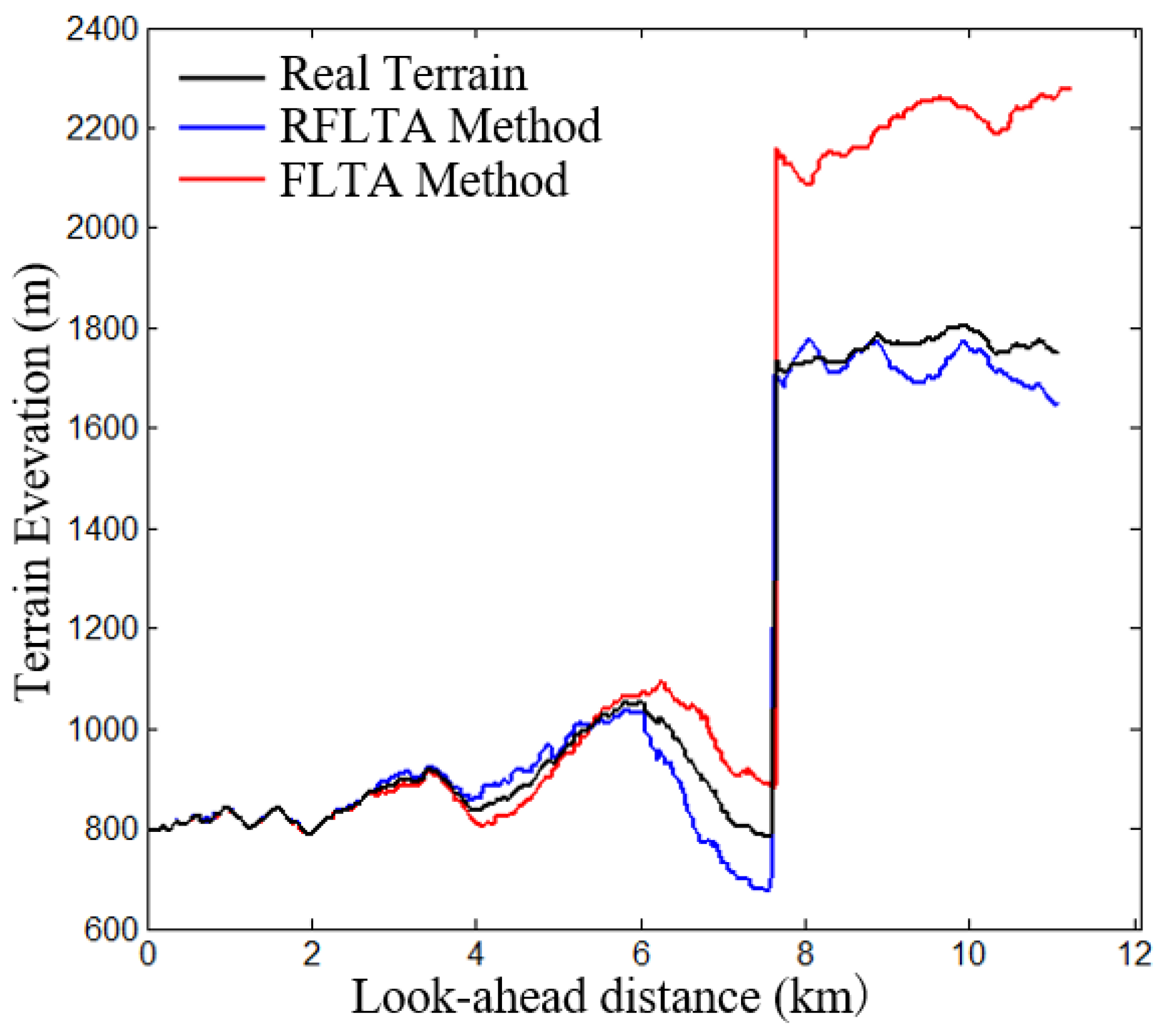
To further test the performance of the RFLTA method, under the same time epoch of the turning flight, the traditional alert envelope and the resilient alert envelope are used to experiment, respectively, and the experimental results are shown in
Figure 9. The horizontal boundaries of the two methods are drawn on the horizontal flight trajectory curve, and the terrain elevations extracted by the two methods are compared with the terrain elevations of the real trajectory, as shown in
Figure 10 and
Figure 11, respectively. For the two turning flights in
Figure 5, we count the interference alarm and the elevation difference with the real terrain profile under two methods, as shown in
Table 2. The interference alarm includes false alarm
NF and missing alarm
NM. If the terrain profile below the real trajectory does not penetrate the alert boundary, and the extracted terrain profile penetrates the alert boundary, it is recorded as a false alarm. Conversely, if the terrain profile below the real trajectory penetrates the warning boundary, and the extracted terrain profile does not penetrate the alert boundary, it is recorded as a missing alarm. The terrain profile information calculates the mean
HM and standard deviation
HS of the elevation difference between the extracted terrain profile and the actual terrain profile.
It can be seen
Figure 9,
Figure 10 and
Figure 11 that the traditional FLTA method has a caution alert, while the RFLTA method does not generate an alert. From the terrain elevation curve directly below the real flight trajectory, it can be seen that the terrain elevation extracted by the RFLTA method better reflects the actual overflown terrain than the traditional FLTA method. As there is no hazardous terrain along the actual flight path, the traditional FLTA has issued a false alarm. Compared to the trapezoidal boundary, the pipe-shaped boundary is closer to the trajectory of the aircraft when it turns.
Table 2 summarizes the alarms under two turning flights. The number of false alarms and missed alarms of the pipe-shaped boundary proposed in this paper is reduced. Moreover, the extracted terrain profile more accurately reflects the actual overflown terrain, thus providing improved terrain awareness and reliability of the HTAWS.


