Article

Flight/Propulsion Integrated Control of Over-Under TBCC Engine Based on GA-LQR Method

School of Power and Energy, Northwestern Polytechnical University, Xi’an 710072, China
*
Author to whom correspondence should be addressed.
Aerospace 2022, 9(10), 621; https://doi.org/10.3390/aerospace9100621
Submission received: 22 September 2022 / Revised: 13 October 2022 / Accepted: 17 October 2022 / Published: 19 October 2022
(This article belongs to the Special Issue Advances in Hypersonic Aircraft Propulsion Technology)

Abstract

:
Turbine-based combined cycle (TBCC) engines are one of the ideal powers for reusable air-breathing supersonic aircraft, but the flight/propulsion integrated control and mode transition restricts its use. This paper takes the Mach 4 over-under TBCC engine as the research object. The inlet is established by the quasi-one-dimensional calculation theory, which can reflect the shock wave position. An iterative method is proposed, which points out that the flow rate in the mode transition depends on the flow capacity. By connecting the input and output that affect each other, the simulation of the coupling characteristics of the aircraft and engine are realized. A GA-LQR-based controller design method is proposed and verified through the aircraft’s climb and mode transition conditions. The simulation shows that the integrated control system can ensure the stability of the aircraft and the safe operation of the engine in the above two situations. During the mode transition process, the aircraft altitude and Mach number fluctuate less than 1%, and the normal shock wave of inlet is in a safe position.

1. Introduction

With the development of supersonic technology, the turbine-based combined cycle engine has become one of the ideal powers for reusable air-breathing supersonic aircraft [1]. Since the 1960s, many verification tests related to TBCC engines have been implemented all over the world. The more well-known ones are the inlet mode transition experiment in the United States [2,3], LAPCAT in Europe [4,5] and HYPR in Japan [6]. However, so far, some technical difficulties such as the mode transition and flight/propulsion integration have not been solved, which restricts the actual use of the TBCC engines [7].
In the process of the mode transition, the operating point of the engine changes greatly, and a fluctuation in the air flow is prone to occur. The intake system of over-under TBCC engines often has a complex shock wave system. The operating conditions of the inlet during the mode transition are related to the turbine engine and the ramjet, so the flow fluctuations may easily cause the inlet not to start. Therefore, safe mode transition becomes a key issue. On the high Mach number transient engine cycle code (HiTECC) platform, Daniel A. Haid developed a calculation simulation model of the TBCC mode transition system and obtained the events and timing of the entire process [8]. Huang and others established an integrated model of a small tandem TBCC engine and analyzed the control law during the mode transition under continuous thrust or flow conditions [9,10]. Zhang and others simulated the mode transition of Ma4 and Ma7 over-under TBCC engines and achieved a smooth transition of the engine thrust and air flow [11,12]. According to the public papers in this field, there are relatively few studies on the mode transition process of over-under TBCC engines, and most of the existing studies do not consider the working state of the inlet.
As TBCC technology is not yet fully mature, there is little research on the TBCC engine control. Daniel, of SPIR-ITECH in the United States, proposed a control strategy for TBCC engines and simulated the performance of the control system during the entire working process [8], but the problem of the coupling between the channels is not considered. Ma, of the Harbin Institute of Technology, has studied TBCC engine control with safety margins, and designed and verified a full envelope performance/safe switching control system [13]. Based on a real-time engine model, Nie, of the Beijing Power Machinery Institute, proposed a multivariable control method for the mode transition of series TBCC engines, which achieved a continuous change of thrust and flow in the mode transition [14]. Except for the last research example, these studies mainly considered steady-state control, and did not consider issues such as the mode transition. At the same time, the research on over-under TBCC mode transition control is still lacking.
Since supersonic aircraft often adopt a flight/propulsion integrated design, when simulating a TBCC engine, it is also necessary to consider the coupling of the aircraft and engine. Turki Alsuwian, at the University of Dayton, proposed a longitudinal adaptive control method for supersonic aircraft [15]. Sun [16] and Zhong [17] studied an adaptive fault-tolerant controller design method under external disturbances, actuator faults and input saturation; then, it was verified through a longitudinal aircraft model. Feng and others [18] designed a coordinated control scheme through a sliding mode control and the dynamic coupling matrix to achieve the precise tracking of the altitude and the velocity. Zheng [19] established an integrated flight/propulsion mode transition simulation system and studied the control law on this basis. The above research mainly considered the aircraft control problem, but the engine model adopted was relatively simple and could not further simulate the coupling characteristics of the aircraft and the engine.
In this paper, the flight/propulsion integrated control is studied on a Mach 4 over-under TBCC engine. First, a TBCC model that can reflect the position of the shock wave in the inlet is established. This model also can perform a mode transition simulation. Then, through co-simulation with the aircraft model, a flight/propulsion integrated model is created. Finally, based on the GA-LQR method, the design method of the flight/propulsion integrated control system is studied. By simulating the climb and mode transition, the flight/propulsion integrated control system was verified.

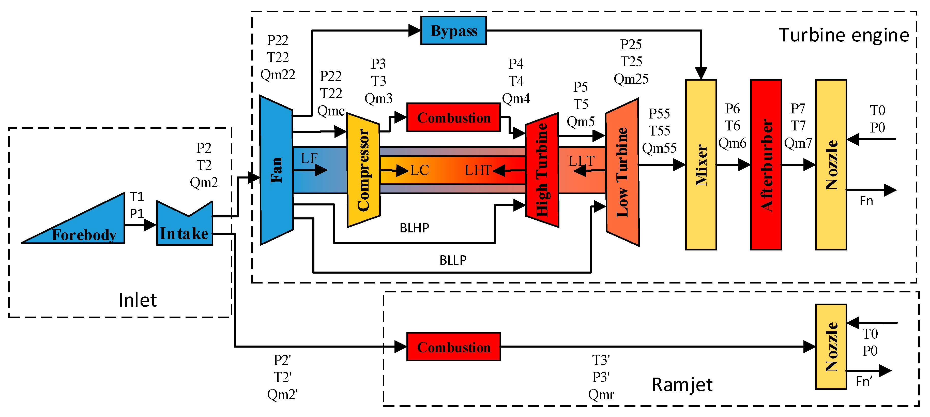
2. Model Establishment of Over-Under TBCC Engine

This research focuses on the Ma4 over-under TBCC, whose structure is shown in Figure 1. The airflow enters the supersonic intake after being compressed by the forebody. After being compressed by the shock wave, it becomes subsonic and then enters the ramjet and the turbine engine through the mode selection valve. Finally, the gas is exhausted through two nozzles.
The over-under TBCC engine mainly includes three parts: an inlet, a ramjet and a turbine engine. Each of the above parts needs its own aerodynamic conditions for safe operation. The inlet needs to provide high-efficiency gas compression capabilities for the other two components within a large Mach number range; the ramjet and the turbine engine need to work under the inlet conditions to provide the required thrust for the aircraft. These three need to match each other when they work.
In order to ensure the gas compression capacity within a larger Mach number range, the inlet adopts a mixed-pressure type, and the forebody has three wedge angles. The ramjet operates in a subsonic combustion regime with a design point of the Ma4 inlet. An amount of 5% of the gas at the inlet of the combustor is used for cooling. The pressure dynamics are considered when doing the modeling. The turbine engine is a twin-shaft mixed-exhaust turbofan engine with a small duct ratio, and the effects of the rotor dynamics, water injection pre-cooling and bleed air are considered in the modeling. In addition, it is considered that the two nozzles exhaust separately and do not affect each other.

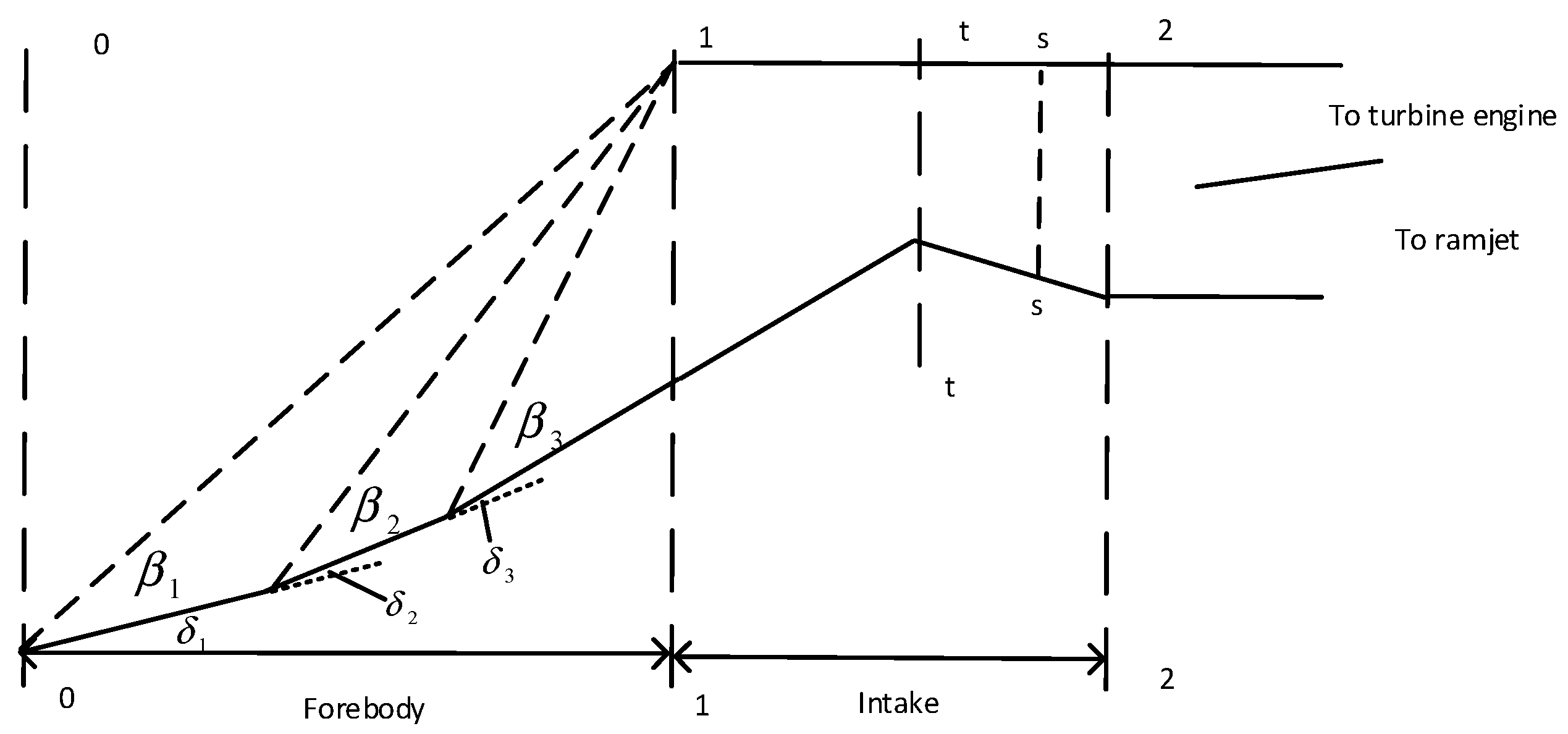
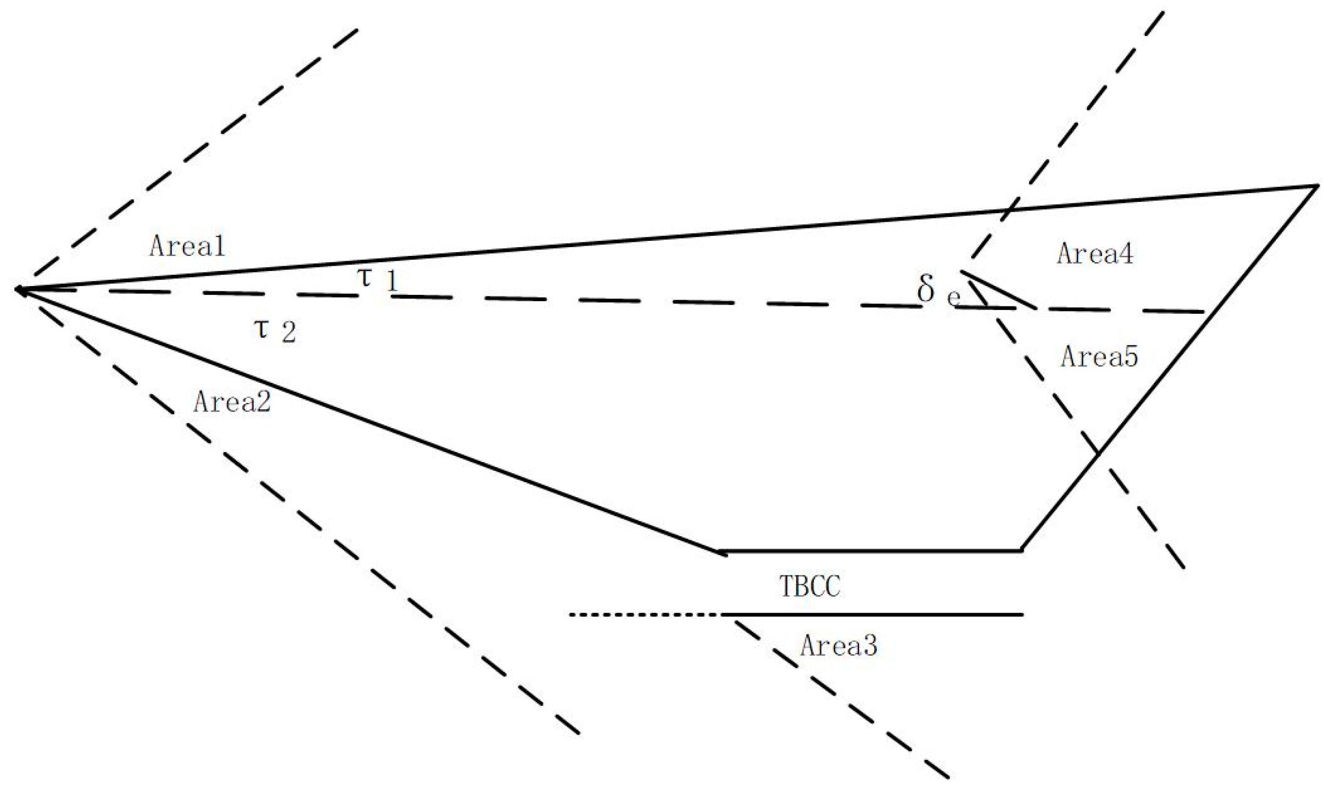
2.1. Mixed Compression Inlet

Generally, when establishing the inlet module of the performance calculation model, the methods of the total pressure recovery coefficient and flow coefficient are mostly adopted. The advantage is that the calculation is simple, but this method will ignore a lot of information inside the inlet. The research object of this paper is a three-wedge angle, four-wave system mixed-pressure inlet. Under the design point, there are three oblique shock waves in the forebody part and a normal shock wave in the internal inlet part. The location of these shock waves determines whether the engine can operate safely, which is very important for the subsequent engine controller design.
Another way to establish an inlet model is to perform CFD calculations. This method can accurately reflect the situation in the inlet with a high accuracy. However, in order to achieve the integrated flight/propulsion control, the inlet needs to consider the influence of the altitude, Mach number, angle of attack and engine back pressure. Due to the large amount of calculation, this method cannot be accepted. At the same time, this method is too slow to be simulated in large numbers.
According to the related research [20], the quasi-one-dimensional method with variable specific heat can achieve results similar to the CFD calculation. Therefore, in response to the above problems, this article proposes the quasi-one-dimensional inlet calculation method, which can reflect the shock wave positions in the inlet and provide a reference for the subsequent controller design; it can also be quickly calculated to achieve a large number of simulation requirements.
Figure 2 shows the inlet’s structure. The dotted line in the figure is the oblique shock wave under the design point, which intersects the lip. Assuming that the function f1 is a zero-dimensional oblique shock calculation formula using the variable specific heat, this part of the precursor model is shown in Equation (1). The subscripts f1 and f2 represent the parameters after the first or second shock wave. The specific oblique shock calculation method is shown in reference [21].
( P f 1 , T f 1 , M a f 1 ) = f 1 ( P 0 , T 0 , M a 0 , α + δ 1 ) ( P f 2 , T f 2 , M a f 2 ) = f 1 ( P f 1 , T f 1 , M a f 1 , δ 2 ) ( P 1 , T 1 , M a 1 ) = f 1 ( P f 2 , T f 2 , M a f 2 , δ 3 )
The input of this module is the total temperature, total pressure, Mach number and angle of attack of the aircraft. The total temperature and total pressure are mainly determined by the altitude and speed of the aircraft. The angle of attack affects the airflow turning angle of the first oblique shock wave; in addition, the angle of attack also affects the airflow compression on the aircraft surface, thereby changing the total pressure.
The internal part is similar to the forebody, which is calculated by the method of the variable cross section tube flow and variable specific heat normal shock wave. The heat transfer effect is not considered here. From front to back, there are four parts: the supersonic contraction, supersonic expansion, normal shock and subsonic expansion. Suppose f2 is the flow balance formula, and f3 is the calculation formula of the shock wave, then the inlet model is as in Equation (2). X = A s / A 1 , which is the ratio of the normal shock wave area to the inlet throat area. If x is less than 1, the shock wave is pushed out of the inlet, and, if x is greater than 2.2, the shock wave is drawn into the combustion. The subscript s represents the cross section of the normal shock wave, and the superscript ’represents the parameters after the normal shock wave.
( P t , T t , M a t ) = f 2 ( P 1 , T 1 , M a 1 , A t / A 1 ) ( P s , T s , M a s ) = f 2 ( P t , T t , M a t , x ) ( P s , T s , M a s ) = f 3 ( P s , T s , M a s ) ( P 2 , T 2 , M a 2 ) = f 2 ( P s , T s , M a s , x , A t / A 2 )
The value of x is affected by the back pressure at the outlet of the intake. It cannot be obtained when calculating this component. Therefore, it is selected as the guessed variable and iteratively determined by the balance equation. In summary, the current modeling method takes into account the influence of different aircraft attitudes and engine states.
It should be noted that the inlet has the total pressure recovery coefficient, as shown in Equation (3). Therefore, the inlet is first ensured to conform to the design characteristics when being modeled. The engine is considered as a whole in the follow-up research. The one-dimensional inlet model is only used to provide certain information for the control system to ensure the safety of the engine. So, some of the flow characteristics inside the inlet are not considered, such as the shockwave reflections and interactions and the boundary layer separation. As will be mentioned in Section 3, the subsequent results will not be affected due to the engine controller
σ = 0.015 M a 0 4 + 0.156 M a 0 3 0.593 M a 0 2 + 0.782 M a 0 + 0.629

2.2. Model Synthesis Iteration

In the TBCC engine, there is a strong correlation between the working state of the intake and the two engines, which can be described by the flow balance equation. Therefore, on the basis of obtaining the characteristics of the three, it is necessary to select appropriate iterative variables, and perform comprehensive iterative calculations on the intake and the two engines to ensure the correct matching. Thus, compared with the traditional model, the over-under TBCC engine needs to add the positive shock wave position mentioned in the previous section as an iterative variable.
The TBCC engine can work in three states: the ramjet mode, turbine mode and mode transition. Therefore, an iterative solution method needs to be set up separately for each working condition. In the ramjet mode, Equation (4) is selected as the balance equation. The states of the inlet and the ramjet state are matched with each other by changing the value of x.
f ( x ) = P 3 P 3 c P 3
P 3 is the total pressure at the outlet of the combustion chamber, obtained from the calculation process of the inlet and combustion chamber; P 3 c is calculated from back to front with the known factor of the nozzle’s throat area and back pressure. This equation actually represents the balance of the flow rate between the intake and the ramjet. By constantly changing the initial guess-value of the component model, when f(x) = 0, the flow rate and pressure of each component of the TBCC engine are balanced, and the inlet matches the ramjet engine.
f ( x ) = Q m 2 Q m 2 f Q m 2
In the turbine mode, in addition to the balance equation of the turbine engine itself, Equation (5) can be added to achieve the flow balance of the intake and the turbine engine. In Equation (5), Qm2 is the inlet flow rate and Qm2f is the calculated flow rate of the fan component.
The mode transition requires a joint solution for the intake, ramjet and turbine engine. For the supersonic gas flow, the downstream fluctuations will not affect the upstream gas. Therefore, if the altitude and Mach number are constant during the transition process, the inlet flow rate is constant, which is not affected by the turbine engine and the ramjet.
Q m i n = Q m 2 + Q m 2
In Equation (6), Qmin is the inlet flow rate; Qm2 is the flow rate of the turbine engine; and Q m 2 is the ramjet’s flow rate. If it is assumed that the thermodynamic parameters of the inlet are uniform, the ramjet and turbine engine’s flow rates can be calculated by the position of the mode transition valve. In the calculation of the ramjet and the turbine engine themselves, a reasonable intake back pressure can be obtained. The two back pressures may be different, so the above assumption that the parameters are uniform is unreasonable. Some of the CFD studies also support this view [22].
In the actual process, the modal transition valve is located behind the normal shock wave. The airflow is at a subsonic speed, so the traditional subsonic intake should be referred to. At this time, the flow rate depends on the engine’s flow capacity. If the inlet flow rate is large, it overflows and the gas enters another flow channel. Therefore, the gas flow rate of a certain flow channel should be added as an iterative variable, and the mode transition process can be solved with Equation (7).
f ( x ,   Q m t ) = P 3 P 3 c P 3 f ( x ,   Q m t ) = Q m 2 + Q m 2 Q m i n Q m i n
From the above analysis, it can be seen that, in the case of the current TCCC engine, the actual modal transition valve position affects the total pressure-loss coefficient, and the flow rate of the two engines mainly depends on their own flow capacity. It should be noted that, in the process of the turbine engine mode and modal conversion, Equation (5) or Equation (7) will be added separately. When the turbine engine is modeled, there are some balance equations to ensure the matching of its components; this article will not discuss them, and the current method does not make any changes to it.
The verification of some of the parameters of the model is shown in Table 1. The geometric parameters are unchanged, and only the control variables are changed relative to expectations. It can be seen that the error in the three working conditions is less than 1%.

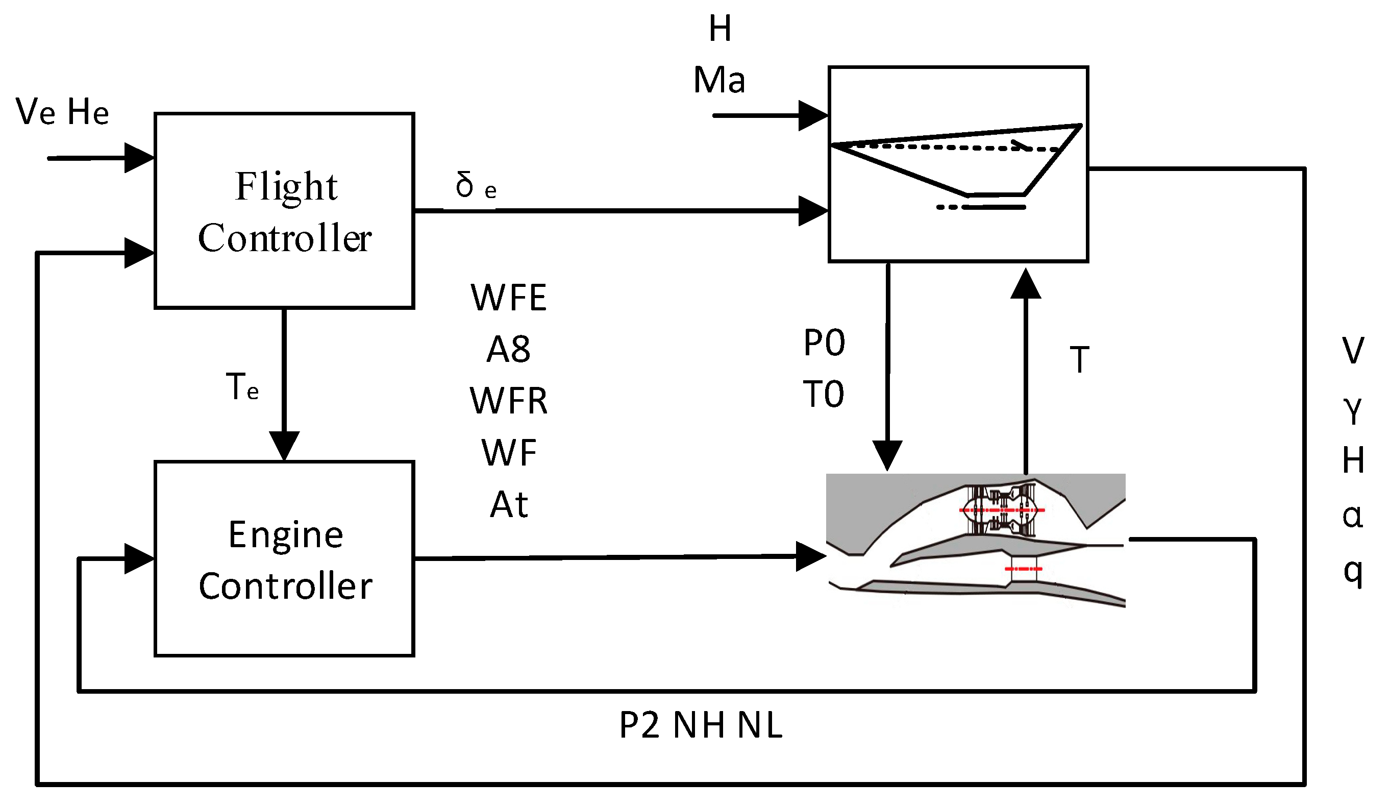
3. Flight/Propulsion Integrated Simulation Implementation

The supersonic vehicle is shown in Figure 3. The model is regarded as a rigid body, and only the longitudinal movement is considered. According to the relevant dynamics knowledge, the longitudinal motion model of the aircraft, as shown in Equation (8), can be obtained. The five state variables are the flight speed V, the flight path angle γ, the flight altitude h, the angle of attack α, and the pitch angle speed q. m is the mass; Iyy is the moment of inertia; g is the acceleration of gravity; r = re + h, re is the radius of the earth; and L, D, T, and Myy are the lift, drag, engine thrust and pitch moment of the aircraft.
V ˙ = T c o s α D m g s i n γ r 2   γ ˙ = L + T s i n α m V ( g V 2 r ) c o s γ V r 2   h ˙ = V s i n γ α ˙ = q γ ˙ q ˙ = M y y I y y
In Equation (8), the thrust is calculated by the TBCC model; and L, D and M y y are fitted by the aerodynamic single-point calculation results [23,24,25]. The fitting results are shown in Equation (9), where ρ is the density; S is the reference area; and c ¯ is the reference length. The main influencing factors of C L , C D and C M are the angle of attack α, flying Mach number Ma and elevator angle δE [24,25,26].
L = 1 2 ρ V 2 S C L D = 1 2 ρ V 2 S C D M y y = 1 2 ρ V 2 S c ¯ C M
When building the flight/propulsion integrated model, the corresponding input and output, which can influence each other, need to be connected. For an aircraft, the influence of the engine is the thrust and its related torque, and these factors will change its attitude. For the engine, the altitude, speed and angle of attack of the aircraft will affect the inlet conditions and geometry of the inlet, which, in turn, affects the state of the engine [27]. After connecting these inputs and outputs, a flight/propulsion integrated model can be obtained to simulate the coupling of the aircraft and the engine.
Figure 4 shows the structure of the flight/propulsion integrated simulation system. Ve and He are the expected speed and altitude; Te is the expected thrust; WFE is the main fuel of the turbine engine; WFR is the turbine engine afterburner fuel; A8 is the turbine engine nozzle throat area; WF is the ramjet fuel; At is the throat area of the ramjet nozzle; and NH and NL are the engine’s high- and low-pressure rotor speeds. The simulation platform is mainly composed of the flight/propulsion integrated model and the controller module. The integrated model is used to simulate the aircraft and the TBCC. The flight controller module receives the control expectation, and then calculates the aircraft elevator angle and engine thrust expectation, according to the control law. The main function of the engine controller module is to receive the desired thrust and calculate the engine control variables. The two work together to achieve the flight/propulsion integrated control.
For the elevator angle, it can be changed at a high frequency without constraints. For the engine control, the WFR and WF are used to ensure that the thrust meets the requirement. WFE ensures that the NH is constant; A8 maintains a constant NL; and At ensures a constant total pressure after the inlet P2. The three loops adopt a closed-loop control to keep the engine working safely. It takes 3 s for the nozzle area to change from the maximum to the minimum, and 1 s for the fuel actuator.

4. Flight/Propulsion Integrated Controller Design and Simulation Result

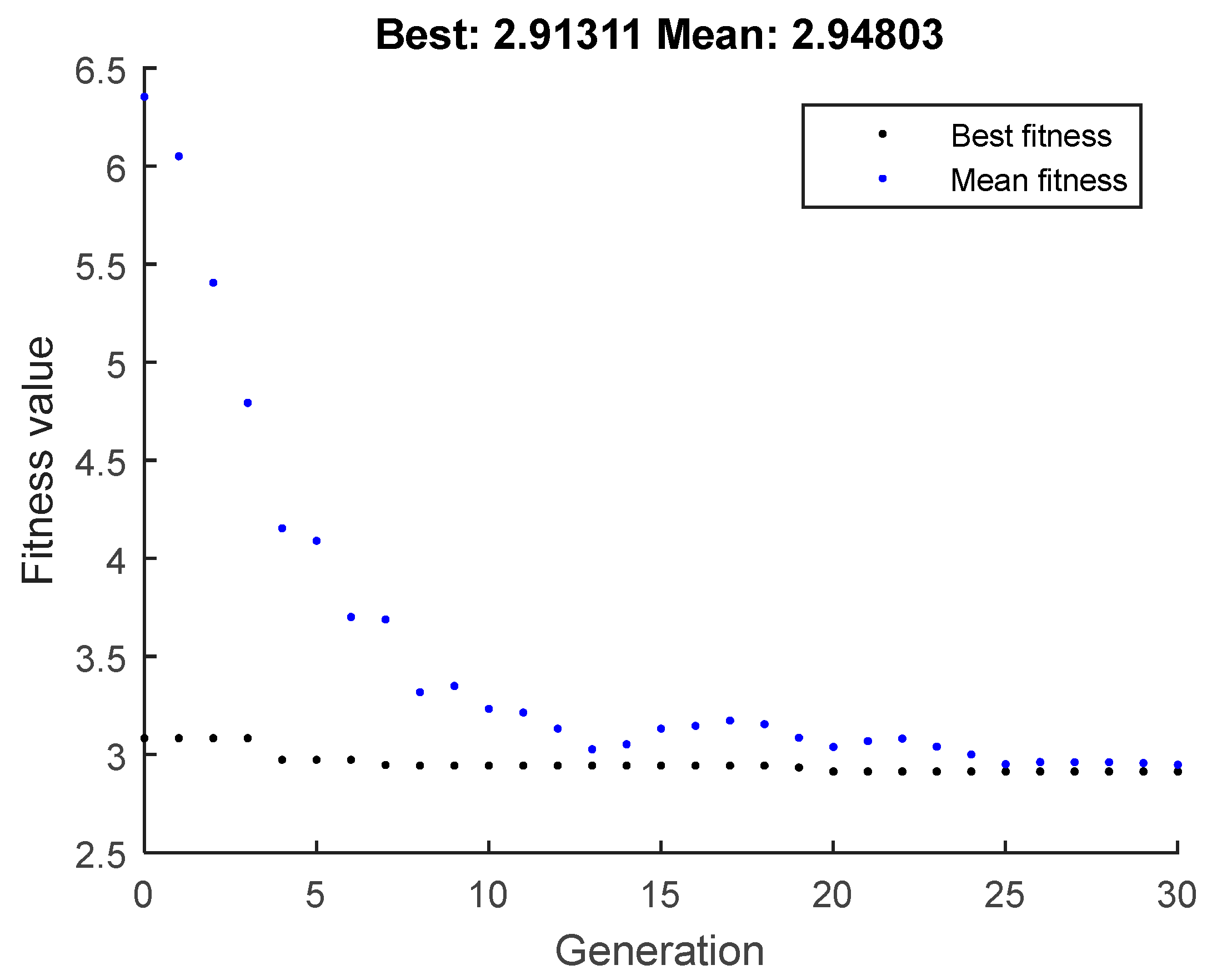
4.1. Controller Design

Flight/propulsion integrated controller design is mainly divided into three parts: finding the steady-state point, the model linearization and the controller design [15]. The first step is to find the state where each derivative in Equation (8) is zero under certain circumstances. It can be achieved by solving a system of nonlinear equations. The model linearization is to perform a Taylor series expansion near the steady-state point to obtain a linear aircraft model, as shown in Equation (10), where Δ y = Δ x = [ Δ V Δ γ Δ H Δ α Δ q ] T and Δ u = [ Δ T e Δ δ E ] T .
{ Δ x ˙ = A Δ x + B Δ u Δ y = C Δ x
The input of the controller consists of two parts.   Δ u * maintains the steady state after the state change. Δud maintains the system stability and dynamic quality. Δ u * is obtained by solving the nonlinear equations, and Δud needs to be designed.
Δ u c = Δ u * + Δ u d
When designing the controller, the main concern is the response of the altitude and speed. So, in order to eliminate the steady-state error, the PI controller is used. First, the state of the system is augmented. The augmented state vector is shown in Equation (11), where * superscript represents the steady-state value after the state has changed.
Δ X P I = [ Δ V   Δ γ   Δ h   Δ α   Δ q   ξ V   ξ h ] T ξ V = ( Δ V Δ V * ) d t = e V d t ξ h = ( Δ h Δ h * ) d t = e h d t
Δud is as follows:
Δ u d = C P I Δ x P I
The matrix CPI is obtained by the linear quadratic index, where Q and R are the weight coefficients. In order to simplify the problem, they are set as a diagonal matrix.
= Δ x P I T Q Δ x P I + Δ u d T R Δ u d
In the end, the controller design becomes the following vector optimization.
d = [ Q γ   Q h   Q α   Q q   Q ξ V   Q ξ h   R β   R δ E   ]
As the state has been expanded, the A and B matrices need to be modified accordingly. The augmented system and corresponding matrix are as follows:
[ x ˙ e ] = [ A 0 0 0 ] [ x   e ] + [ B 0 0 I ] [ u e ]

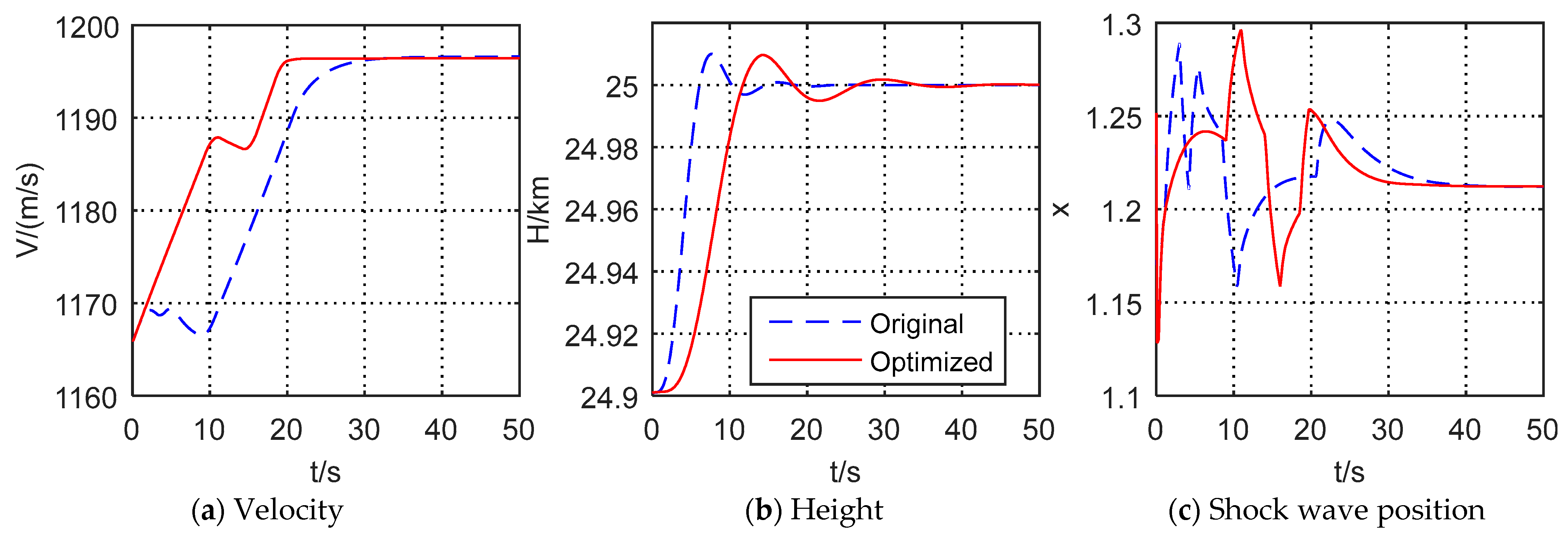
4.2. Climbing Simulation and Result

First, take the climbing process as an example to illustrate the controller optimization method. The starting point is at an altitude of 24.9 km and a Mach number of 3.9; the end point is at an altitude of 25 km and a Mach number of 4. It should be noted that the TBCC works in the ramjet mode at this time. The ramjet uses an open-loop control of the fuel flow to change the engine state. The throat area of the nozzle controls the pressure before combustion in a closed loop to further ensure the normal operation of the inlet.
J ( d ) = m = 1 6 [ ω m I m ( d ) ]
The performance index is shown in Equation (17), where ωm is the weighted value, and Im is the performance index. Performance Index 1 represents whether the state of the aircraft does not diverge under the input of the controller, and this represents its stability, to a certain extent. The performance indicators of No. 2–6 are shown in Table 2. The weight of the system stability is 10, and the weight of the other performance indices is 1.
In order to reduce the computational burden, the weight matrix is set as a diagonal matrix, so the GA needs to optimize eight parameters. The lower limit of the parameters is 0.001, and upper limit is 100.
It can be seen from Figure 5, with the optimization of the algorithm, the average evaluation function drops rapidly, and finally fluctuates within a certain range. The optimal evaluation function slowly decreases, and finally stabilizes at a certain value, which shows that the algorithm has found the local optimal solution to this optimization problem. After the optimization, the optimal set of parameter evaluation indexes is 2.91, which shows that the performance of the system has been optimized under the design indexes.
The results before and after the optimization are shown in Figure 6. The aircraft speed responses are significant increased, in which the speed settling time is reduced from 29 s to 20 s, and the altitude settling time is changed from 9 s to 14 s, but still within 20 s. At the same time, under this group of controllers, there is no steady-state error in the altitude and speed response. Before and after the controller is modified, there is no obvious change in the minimum shock wave position of the inlet, which shows that the current controller can optimize the step response of the altitude and speed with the margin unchanged.
At the beginning of the climb, the height increases faster than the speed, so it reaches the expected value first. At this time, the controller starts to change the state of the aircraft, resulting in fluctuations of the speed. For the controller, before the optimization, the height increases too quickly. Therefore, it takes a longer time to adjust the status of the aircraft, and the speed cannot be increased for 9 s. For the optimized controller, by slowing down the altitude response, that time is reduced to 5 s. The flight status changes faster.
In the whole process, the increase in height will reduce the flow at the engine inlet, and the normal shock wave will move backward. On the contrary, a rising speed increases the engine inlet flow rate and makes the normal shock wave move forward. So, in the two simulations, the normal shock wave moved back and forth. But, under the action of the closed-loop controller, the normal shock wave in the inlet gradually returned to a safe position, and finally a margin of 0.2 was guaranteed. Therefore, the safe operation of the inlet can be ensured by controlling the inlet pressure before combustion

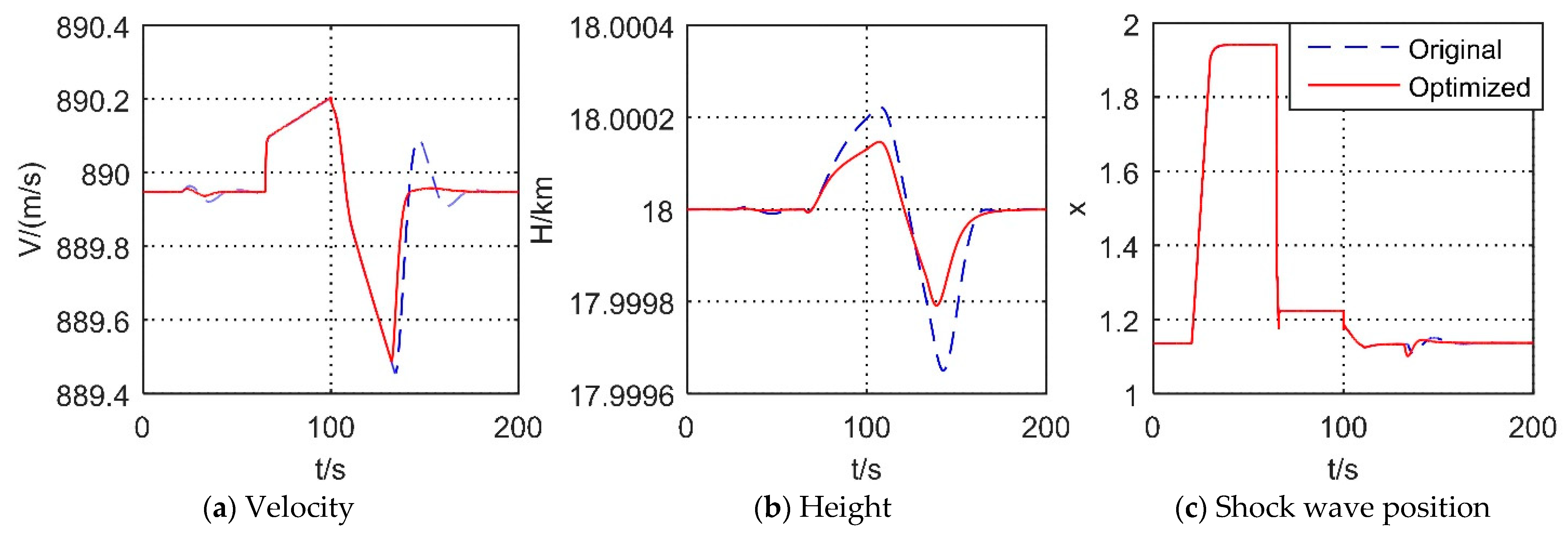
4.3. Flight/Propulsion Integrated Mode Transition Simulation Result

Similarly, the above-mentioned controller design and optimization methods can be used to perform flight/propulsion integrated mode transition simulations. It should be noted that the Mach number is 3 during the modal transition process, and the aircraft needs to be linearized. At the beginning of the mode transition, the ramjet is in the cold state, and the turbine base is in the afterburner state. Then, the ramjet ignites and gradually increases its fuel flow, while the turbine engine gradually reduces its fuel flow. Finally, the turbine engine closes the afterburner and continues to throttle. In this process, the performance indicators are the stability, speed and altitude fluctuations, and the weighting values are the same as above.
The simulation result is shown in Figure 7. It can be seen that both controllers can ensure the stability of the aircraft during the mode transition process. However, after the optimization, the altitude and Mach number fluctuations of the aircraft are significantly reduced, which shows that the generic algorithm is effective for the selection of the LQR parameters.
At 20 s, there was a small fluctuation in the attitude of the aircraft, but, after the controller was optimized, the fluctuations in altitude and speed were reduced by more than 50%. At the same time, the thrust change was reduced from 1.7% to 0.9%. This was caused by the pre-opening of the nozzle throat area. The reason for the pre-opening is that the ignition of the ramjet will cause the engine’s flow capacity to drop rapidly, thereby causing the normal shock wave to move to the throat. After the pre-opening, the positive shock wave will move to the outlet of the inlet, leaving a certain margin to ensure the safe operation of the engine during its ignition. After the pre-opening, the flow rate of the ramjet will increase, and its negative thrust will increase accordingly. Also, the total thrust drops, but it will return to stability under the action of the flight/propulsion integrated controller.
At 65 s, the ramjet ignites, so the thrust increases instantaneously, causing the speed and altitude of the aircraft to change rapidly. At this time, the normal shock wave moves quickly to the throat, changing from 1.9 to 1.2, but there is a margin of more than 20% before and after the whole process.
From 60 s to 100 s, the thrust of the turbine engine gradually decreases, and the thrust of the ramjet gradually increases, until the afterburner is turned off at 100 s. At this time, the thrust changes down instantly, and the flight’s altitude and speed also begin to decrease. After 100 s, the thrust is mainly provided by the ramjet. Under the flight/propulsion integrated control system, the attitude of the aircraft gradually stabilizes, and the mode transition process ends. During the entire mode transition process, it takes 185 s to stabilize the attitude of the aircraft before the controller is optimized, and only 145 s after the optimization. At the same time, the altitude fluctuation is reduced by 60%.
In summary, the flight/propulsion integrated controller can ensure the stability of the aircraft under this mode transition control law. During the whole process, the fluctuation of speed and altitude does not exceed 1%, and there is no steady error. At the same time, the engine control system can ensure that the thrust changes as expected, and also that the normal shock wave of the inlet is in a safe position during the whole process.

5. Conclusions

An over-under TBCC engine model for control is established. The inlet module is established by the quasi-one-dimensional theory through the shock calculation formula and flow balance formula. This can reflect the shock wave position under different conditions and solve the problem of determining the inlet starting. The inlet meets the requirement of the total pressure recovery coefficient and can be calculated quickly for the controller design.
An iterative method is proposed for the mode transition. The iterative variables and balance equations are designed for the ramjet mode, turbine engine mode and mode transition, respectively. Through the analysis of the flow rate balance, it is shown that the flow rate of the different channels depends on the flow capacity. The final TBCC model error is less than 1% under the three working conditions
A framework for a flight/propulsion integrated control simulation system is proposed. The integrated system is established by connecting the inputs and outputs that affect each other, which achieves the simulation of the coupling characteristics of the aircraft and the engine.
Based on the GA-LQR theory, a design method for the flight/propulsion integrated controller is established. The simulation shows that the controller can achieve the stability of the aircraft attitude and the safe operation of the engine under the conditions of the climb or mode transition. The settling time of the climbing process is less than 20 s, and the overshoot is less than 10%. During the mode conversion process, the altitude and speed of the aircraft fluctuate less than 1%, and the normal shock wave in the inlet is in a safe position. The current flight/propulsion integrated controller can deal with different situations. This research lays the foundation for the realization of supersonic vehicle flight/propulsion integrated controls.

Author Contributions

Conceptualization, Y.G. and H.Y.; methodology, H.Y. and J.W.; software, H.Y. and J.W.; validation, H.Y. and J.W.; formal analysis, H.Y.; investigation, H.Y. and J.W.; resources, Y.G. and X.Y.; data curation, H.Y.; writing—original draft preparation, H.Y.; writing—review and editing, H.Y.; visualization, H.Y.; supervision, Y.G. and X.Y.; project administration, Y.G.; funding acquisition, Y.G. All authors have read and agreed to the published version of the manuscript.

Funding

This research was funded by National Science and Technology Major Project, grant number J2019-V-0003-0094.

Institutional Review Board Statement

Not applicable.

Informed Consent Statement

Not applicable.

Data Availability Statement

Not applicable.

Conflicts of Interest

The authors declare no conflict of interest. The funders had no role in the design of the study; in the collection, analyses, or interpretation of the data; in the writing of the manuscript; or in the decision to publish the results.

References

  1. Le, D.; Vrnak, D.; Slater, J. A Framework for Simulating Turbine-Based Combined—Cycle Inlet Mode-Transition. In Proceedings of the AIAA/ASME/SAE/ASEE Joint Propulsion Conference & Exhibit, Atlanta, GA, USA, 30 July–1 August 2012. [Google Scholar] [CrossRef] [Green Version]
  2. Saunders, J.D.; Stueber, T.J.; Suder, K.L. Testing of the NASA Hypersonics Project’s Combined Cycle Engine Large Scale Inlet Mode Transition Experiment (CCE LIMX). In Proceedings of the 58th Joint Army-Navy-NASA-Air Force (JANNAF) Propulsion Meeting, Arlington, TX, USA, 1 January 2012. [Google Scholar]
  3. Foster, L.E.; Saunders, J.D.; Sanders, B.W. Highlights from a Mach 4 Experimental Demonstration of Inlet Mode Transition for Turbine-Based Combined Cycle Hypersonic Propulsion. In Proceedings of the 48th AIAA/ASME/SAE/ASEE Joint Propulsion Conference & Exhibit, Atlanta, GA, USA, 30 July–1 August 2012. [Google Scholar] [CrossRef]
  4. Steelant, J. Achievements Obtained for Sustained Hypersonic Flight within the LAPCAT Project. In Proceedings of the 15th AIAA Inter-national Space Planes and Hypersonic Systems and Technologies Conference, Dayton, OH, USA, 28 April–1 May 2008. [Google Scholar] [CrossRef]
  5. Bulman, M.J.; Siebenhaar, A. Combined Cycle Propulsion: Aerojet Innovations for Practical Hypersonic Vehicles. In Proceedings of the 17th AIAA International Space Planes and Hypersonic Systems and Technologies Conference, San Francisco, CA, USA, 11–14 April 2011. [Google Scholar] [CrossRef]
  6. Miyagi, H.; Kimura, H.; Kishi, K. Combined Cycle Engine Research in Japanese HYPR Program. In Proceedings of the 34th AI-AA/ASME/SAE/ASEE Joint Propulsion Conference and Exhibit, Cleveland, OH, USA, 13–15 July 1998. [Google Scholar] [CrossRef]
  7. Liu, J.; Yuan, H.; Ge, N. Turbine Based Combined Cycle Inlet Mode Transition at Different Operation Conditions. In Proceedings of the 21st AIAA International Space Planes and Hypersonics Technologies Conference, Xiamen, China, 6–9 March 2017. [Google Scholar] [CrossRef]
  8. Daniel, A.H.; Eric, J.G. Integrated Turbine-Based Combined Cycle Dynamic Simulation Model. In Proceedings of the 58th Joint Army-Navy-NASA-Air-Farce (JAN-NA) Interagency Propulsion Meeting, Arlington, TX, USA, 18 April 2011. [Google Scholar]
  9. Huang, H.; Wang, Z.; Cai, Y. Analysis of mode transition with thrust smoothing of small turbine/ramjet combined cycle engine. J. Aerosp. Power 2010, 24, 2756–2762. [Google Scholar] [CrossRef]
  10. Huang, H.; Wang, Z.; Liu, Z. Exploring Mode Transition with Air Mass Flow Smoothing of Small Turbine/Ramjet Engine (TRE). J. Northwest. Polytech. Univ. 2010, 28, 234–239. [Google Scholar] [CrossRef]
  11. Zhang, M.; Zhou, L.; Wng, Z. Simulation and Analysis of Mode Transition Performance for an Over-Under TBCC Engine. J. Propuls. Technol. 2018, 39, 35–43. [Google Scholar] [CrossRef]
  12. Zhang, M.; Wang, Z.; Liu, Z. Analysis of Mode Transition Performance for a Mach 4 Over-Under TBCC Engine. J. Propuls. Technol. 2017, 38, 15–322. [Google Scholar] [CrossRef]
  13. Ma, J. Control Study for Over-Under TBCC Engine with Safety Boundaries. Master’s Thesis, Harbin Institute of Technology, Harbin, China, 2018. [Google Scholar]
  14. Nie, L.; Li, Y.; Dai, D. Study on Mode Transition Multi-Variable Control for Turbine-Based Combined Cycle Engine. J. Propuls. Technol. 2017, 38, 968–974. [Google Scholar] [CrossRef]
  15. Alsuwian, T.M.; Ordonez, R.; Jacobsen, L. Adaptive Control for Longitudinal Dynamics of Hypersonic Vehicle at Subsonic Speeds. In Proceedings of the AIAA Modeling and Simulation Technologies Conference, Denver, CO, USA, 5–9 June 2017. [Google Scholar] [CrossRef]
  16. Sun, J.G.; Song, S.M.; Peng, L. Adaptive anti-saturation fault-tolerant control of hypersonic vehicle with actuator faults. Proc. Inst. Mech. Eng. Part G J. Aerosp. Eng. 2019, 233, 2066–2083. [Google Scholar] [CrossRef]
  17. Zhong, Z.Y.; Sun, J.G. Robust fault-tolerant control design for hypersonic vehicle with input saturation and actuator faults. Proc. Inst. Mech. Eng. Part G J. Aerosp. Eng. 2021, 236, 1563–1576. [Google Scholar] [CrossRef]
  18. Feng, X.; Wang, Y.; Wu, Q. Longitudinal coordination control of hypersonic vehicle based on dynamic equation. Proc. Inst. Mech. Eng. Part G J. Aerosp. Eng. 2019, 233, 5205–5216. [Google Scholar] [CrossRef]
  19. Zheng, J.; Chang, J.; Ma, J. Modeling and analysis for integrated airframe/propulsion control of vehicles during mode transition of Over-Under Turbine-Based-Combined-Cycle engines. Aerosp. Sci. Technol. 2019, 95, 105462. [Google Scholar] [CrossRef]
  20. Fu, Q. Research on the Control Law of Dual Mode Scramjet. Ph.D. Thesis, Northwestern Polytechnical University, Xi’an, China, 2019. [Google Scholar]
  21. Qin, L. Solution of Shock with Variable Specific Heat for Calculation of Hypersonic Inlet. J. Aerosp. Power 2000, 15, 105–108. [Google Scholar] [CrossRef]
  22. Huang, H.; Huang, G.; Zuo, F. CFD Simulation of TBCC Inlet Based on Internal WaveRider Concept. In Proceedings of the 21st AIAA International Space Planes and Hypersonics Technologies Conference, Xiamen, China, 6–9 March 2017. [Google Scholar] [CrossRef]
  23. Yu, H.; Guo, Y. Modeling and Simulation of Parallel TBCC Aircraft/Engine Integrated System. In Proceedings of the 39th Chinese Control Conference (CCC), Shenyang, China, 27–29 July 2020. [Google Scholar] [CrossRef]
  24. Jia, L.; Chen, Y.; Gao, Y. Integrated design and optimization of high speed vehicle and turbine based propulsion system. In Proceedings of the 21st AIAA International Space Planes and Hypersonics Technologies Conference, Xiamen, China, 6–9 March 2017. [Google Scholar] [CrossRef]
  25. Marrison, C.I.; Stengel, R.F. Design of Robust Control Systems for a Hypersonic Aircraft. J. Guid. Control. Dyn. 1998, 21, 58–63. [Google Scholar] [CrossRef]
  26. Qu, X.; Wang, J.; Ren, Z. Hypersonic Vehicle Longitudinal Control Using Adaptive Time-varying Terminal Sliding Modes. In Proceedings of the 12th Biennial International Conference on Engineering, Construction, and Operations in Challenging Environments, Honolulu, HI, USA, 14–17 March 2010. [Google Scholar] [CrossRef]
  27. Zheng, J.; Chang, J.; Ma, J. Analysis of aerodynamic/propulsive couplings during mode transition of over-under turbine-based-combined-cycle engines. Aerosp. Sci. Technol. 2020, 99, 105773. [Google Scholar] [CrossRef]
Figure 1. The structure of Ma4 over-under TBCC.
Aerospace 09 00621 g001
Figure 2. Schematic diagram of the inlet.
Aerospace 09 00621 g002
Figure 3. Schematic diagram of supersonic vehicle.
Aerospace 09 00621 g003
Figure 4. Structure of flight/propulsion integrated control system.
Aerospace 09 00621 g004
Figure 5. Result of genetic algorithm.
Aerospace 09 00621 g005
Figure 6. Comparison before and after controller’s optimization of the climb.
Aerospace 09 00621 g006
Figure 7. Comparison before and after controller’s optimization of the mode transition.
Aerospace 09 00621 g007
Table 1. Engine parameters verification.
Working
Status
Parameter CategoryDesign ParametersModel
Parameters
Percentage
Error
Ma = 4
H = 25 km
α = 1.8
Air flow Rate50.61 kg/s50.6102 kg/s0.004%
Total Pressure before Combustion201.2 kPa201.7 kPa0.2%
Thrust26.13 kN26.16 kN0.1%
Ma = 4
H = 25 km
α = 1.4
Air flow Rate50.61 kg/s50.6102 kg/s0.004%
Total Pressure before Combustion201.2 kPa201.4 kPa0.1%
Thrust32.73 kN32.85 kN0.4%
Ma = 3
H = 18 km
α = 1.8
Total Pressure before Combustion185.49 kPa185.52 kPa0.02%
Table 2. Performance index.
I V , T s 50 5% Settling Time of V Divided by 20 s
I H , T s 50 3% Settling Time of H Divided by 20 s
I V , O S 05 Overshoot of V Divided by 5%
I H , O S 05 Overshoot of H Divided by 5%
Publisher’s Note: MDPI stays neutral with regard to jurisdictional claims in published maps and institutional affiliations.

