Article

Effect of Fuel-Injection Distance and Cavity Rear-Wall Height on the Flameholding Characteristics in a Mach 2.52 Supersonic Flow

Science and Technology on Scramjet Laboratory, National University of Defense Technology, Changsha 410073, China
*
Author to whom correspondence should be addressed.
Aerospace 2022, 9(10), 566; https://doi.org/10.3390/aerospace9100566
Submission received: 13 August 2022 / Revised: 19 September 2022 / Accepted: 21 September 2022 / Published: 29 September 2022
(This article belongs to the Special Issue Aerospace Combustion Engineering)

Abstract

:
The ethylene-fueled flameholding characteristics of a cavity-based scramjet combustor are experimentally and numerically investigated. The test facility used the air heater, which heats air from room temperature to total temperature 1477 K. A nozzle is installed behind the heater outlet to increase the air speed to Mach 2.52. Two cavity geometries with different rear-wall heights of 8 mm and 10 mm and two injection distances upstream of the cavities of 10 mm and 40 mm are compared to show the effect of these parameters. The CH* spontaneous emission images obtained by dual-camera synchronous shooting and the wall-pressure distribution obtained by a pressure-scan system are used to capture the flame dynamics. The global equivalence ratio range for different combination schemes is controlled from 0.14 to 0.27 in this paper. The results show that the conventional cavity (the rear-wall height is 10 mm) and the shorter injection distance can effectively decrease the lean blowoff limit of the combustor, while the rear-wall-expansion cavity (the rear-wall height is 8 mm) and the longer injection distance can effectively increase the rich blowoff limit. Compared with the injection distance, the rear-wall height of the cavity has little effect on the oscillation distribution of the shear layer-stabilized flame. However, the fuel-injection distance and cavity rear-wall height both have great influence on the spatial distribution of the flame.

1. Introduction

The complex flow field environment in scramjet combustors brings great challenges to flame stabilization and efficient combustion, so flame stabilization in the supersonic combustor usually requires the help of various flame stabilizers, such as transverse injection [1], backward steps, slopes, struts, and cavities [2,3,4,5,6], etc. For the case where the fuel transverse injection works alone, it is difficult to stabilize the flame in the supersonic flow [7,8,9] unless the total enthalpy of the incoming flow reaches the self-ignition condition of the fuel. Therefore, it is necessary to select a suitable flameholder combined with transverse injection to achieve stable combustion. The cavity has attracted extensive attention and research because of its simple structure, great flame stabilization effect, low intrusion of flow field, small total pressure loss, and relatively simple thermal protection [10,11,12,13,14]. Although the flow-channel geometry of a scramjet combustor based on q cavity flameholder is very simple, the flow, mixing, and combustion mechanisms are extremely complex. The flame stabilization process is affected by many factors and the mechanism is not completely clear yet, so it is necessary to conduct more in-depth research.
Supersonic combustion characteristics are usually affected by flow conditions, injection schemes, cavity configurations, and other factors. Though the design scheme of multiple injection holes and cavities is often adopted in practice, the method of single injector combined with single cavity is usually adopted in fundamental research. The influence of transverse injection ethylene upstream of the cavity on flame stabilization has received extensive attention in recent years. Micka et al. [15] investigated the combustion characteristics of fuel injected upstream of the cavity in flight Mach numbers of 4.3–5.4 and observed two flame stabilization modes. By changing the injection distance and the length:depth ratio of the cavity, Li et al. [16] observed the flame stabilization mode transition of the cavity shear layer and jet wake from the high-speed image of flame spontaneous light. They concluded that the injector position and cavity length:depth ratio should be comprehensively considered from combustion stability and combustion heat release, and the flame should be in cavity shear-layer stabilization mode as much as possible under the premise of ensuring proper air–fuel mixing. Wang et al. [8] observed that the combustion tended to be more stable with increased cavity length:depth ratio or decreased upstream transverse injection distance. Zhang et al. [17] found that increasing the distance between the injector and cavity would have a great impact on the stability of combustion in the case of a high equivalence ratio.
In terms of cavity configuration, scholars name and classify cavities according to their configuration characteristics as open cavity, closed cavity, and transitional cavity. In recent years, a new type of cavity with the height of the rear wall slightly lower than the height of the leading edge has received extensive attention [18]. In this paper, it is called the rear-wall-expansion cavity [19]. It can be considered that the rear-wall-expansion cavity is the transition between the conventional cavity and the back step in structure. Therefore, its performance should be in between. Yang et al. [20] conducted experimental and simulation studies on the reaction flow fields with rear-wall-expansion cavities. The results showed that combustion efficiency will gradually decrease as the rear-wall height decreases, and even the ignition cannot be successful. The main reason for this phenomenon is that as the rear-wall height of the cavity decreases, the gas flows through the cavity into a larger flow channel, experiencing the process of expansion acceleration and intensifying the impact on the rear wall of the cavity combined with the reduced volume of the recirculation region, so the flame stabilization condition in the cavity is deteriorated. Therefore, the concept of rear-wall-expansion limit is proposed and suggested to be maintained at 20–40%. Cai et al. [21] investigated the combustion characteristics of cavities with different rear-wall-expansion rates. It was found that the rear-wall-expansion cavity can keep the flame into shear-layer stabilization mode at a high equivalence ratio. Many studies [17,20,21,22] show that the transition from combustion mode to jet wake mode can be delayed by using the rear-wall-expansion cavity, and this ability will be gradually enhanced with the increase of rear-wall-expansion rate within a certain range. It has a positive effect on preventing the undesirable combustor thermal choke under a high equivalence ratio. However, there are few research on the rear-wall-expansion cavity, and its flame stabilization characteristics still need to be further studied.
The flame in the combustor is not always stable, and flame oscillation can lead to flame blowoff or local pressure overload in some situations, which can result in engine shutdown or structural damage. Therefore, investigation of the dynamic characteristics of flame blowoff and further discovery of the influencing factors in extending the flame stability limits of combustors are needed. The phenomenon of flame blowoff is mainly caused by the local mixture being below the flammable limits [23,24]. The flame front becomes more distorted with a high Karlovitz number [25,26], and the local flame blowoff phenomenon may be induced by turbulence under a high Karlovitz number [27]. Furthermore, there are many factors that affect the blowoff limits, such as the cavity geometry, injection scheme, and incoming flow parameters, etc. Rasmussen et al. [28] observed that the flame blowoff fuel flow rates were higher for floor injection than for rear-wall fueling. This was attributed to larger quantities of unburned fuel bypassing the recirculation zone and ultimately escaping the cavity in the case of floor injection. It was also observed that blowout limits were affected by changing the cavity closeout angle. Owens et al. [29] investigated flame stability in a cavity with upstream kerosene injection. The effects of air-stagnation temperature that strongly altered the air entrainment were underlined and the local equivalence ratio were found to be key factors affecting flame stability. Wang and Song et al. [30] studied flame stability in a scramjet combustor with kerosene injection upstream of the cavity, and found that the lean blowoff limit increased with increasing total pressure or decreasing total temperature, and total temperature had a more significant effect. Wang et al. [31] investigated the lean blowoff characteristics in an ethylene-fueled scramjet combustor with different sized cavity flameholders. Flow residence time plays a leading role in small cavities, causing lean ignition and blowoff limits to decrease with increasing cavity size. The local equivalence ratio plays a leading role in large cavities, causing lean ignition and blowoff limits to increase with cavity size.
The primary goal of this study was to expand the understanding of the flame stabilization mechanism of the cavity flameholder. Ethylene flames with different rear-wall heights and injection distances in the supersonic combustor are compared and analyzed in terms of the flame structure, combustion heat release, and flame oscillation. In addition, the effects of flameholder geometry and injection distance on stability limits are analyzed to provide guidelines for the design of scramjet combustors.

2. Experimental and Computational Description

2.1. Experimental Setup

The experiments were performed in a direct-connect wind-tunnel facility at the National University of Defense Technology. The facility is composed of an air heater, a scramjet combustor, a fuel-supply system, and a measure control system. An Ma2.52 nozzle is installed behind the air heater that heats air with mass flow rate of about 0.75 kg/s from room temperature to total temperature ( T 0 ) 1477 K and increases the total pressure ( P 0 ) of vitiated air to 1.44 MPa by means of air/O2/alcohol combustion. Detailed inflow conditions are listed in Table 1.
The details of the model scramjet are shown in Figure 1. The entrance of the isolator is a rectangle with a width of 50 mm and a height of 30 mm, which extends straight to the combustor entrance. The top wall and side wall of the combustor are both provided with windows for optical measurement. A cavity with rear-wall height of 10 mm or 8 mm can be employed as flameholder and installed on the lower wall of the combustor, in accordance with non-expansion (baseline) or slight expansion effects. Both cavity flameholders have the same front-wall depth of 10 mm and rear-wall ramp angle φ = 45°, but they have different lengths of bottom wall, i.e., 40 mm and 42 mm, respectively. In order to study the combustion characteristics at different injection distances, two fueling injectors of 3 mm diameter are located 10 mm and 40 mm upstream of the cavity. For simplicity, the label “HhDdERer” is used to denote the operation condition with cavity rear-wall height H = h, injection distance D = d, and the global equivalence ratio ER = er.
A spark-ignition plug is mounted on the cavity bottom wall 17 mm away from the cavity front wall, as shown in Figure 2. The capacitive-discharge spark system is the most frequently used electrostatic ignition source in practice. An igniter with excitation energy of 5 J and excitation frequency of 50 Hz is used in this study. Synchronous imaging using two cameras is used. The high speed-cameras are equipped with a center wavelength of 310 nm, full height half width of 10 nm. An Edmund Optics 65-198 filter is placed in the direction of the observation window on the side wall and the top wall of the wind tunnel, in order to obtain the dynamic evolution of CH* spontaneous emission from different perspectives. The camera is set at 10,000 fps with a shutter time of 1/20,000 s. Static pressure taps with sampling frequency of 200 Hz are installed along the bottom wall of the combustor to obtain the wall-pressure distribution. The pressure transducers have uncertainties of ±0.5% in this study. During the experiment, the injection pressure, mass flow rate, and other data can be measured by the data-acquisition system on the experimental platform.

2.2. Computational Setup

Three-dimensional steady Reynolds-averaged Navier–Stokes (RANS) equations [32] simulation are employed to explore the fuel distributions of nonreacting flow in the scramjet combustor for different cavity rear-wall heights. The RANS method can reflect low-field characteristics with lower computational cost than LES (large eddy simulation) and DNS (direct numerical simulation). The governing equations are expressed in vector form as follows [33]:
ρ t + ( ρ u i ) x i = 0 ( ρ u i ) t + ( ρ u i u j ) x i + P x i = τ i j x i ( ρ E ) t + [ ( ρ E + p ) u i ] x i = ( τ i j u j + λ T x i + ρ n = 1 N D n h n Y n x i ) x i ( ρ Y n ) t + ρ Y n u i x i = ( ρ D n Y n x i ) x i + ω . n
where N is the total number of components. Y n , D n and h n are the mass fraction, mean mass diffusion coefficient, and total enthalpy of component n, respectively. ρ , P , T , λ , u i and u j are the density, pressure, temperature, thermal conductivity and velocity component of the x i and x j directions of mixture gas, respectively. τ ij is the viscous shear stress tensor:
τ ij = μ ( u i x j + u j x i 2 3 u k x k δ i j )
The mixture gas follows the ideal gas equation of state:
p = ρ R T n = 1 N Y n M n
where R is the gas constant of the mixture and M n is the molar mass fraction of component N.
E is the total energy per unit volume of the multicomponent mixture, defined as:
E = n = 1 N Y n h n p ρ + 1 2 u k u k
The equations are solved along with the density-based (coupled) double-precision solver of commercial fluid software Fluent. The two-equation SST k-ω turbulence model [34] is used, which is insensitive to initial values and has proved to be very suitable for mixing layer and jet-flow problems [35,36,37]. The turbulence model equation is:
ρ k t + ρ k u i x i = [ Γ k k x j ] x j + G k Y k + S k ρ w t + ( ρ w u i ) x i = [ Γ w w x j ] x j + G w Y w + S w + D w
where Γ k and Γ w are the effective diffusion coefficients of k and ω . Y k and Y w are dissipative terms. D w is the cross-diffusion term. G k and G w represent the generation of turbulent kinetic energy and specific dissipation, respectively. S k and S w are the source terms that are defined. More information on the above formulas can be found in the literature [38,39].
A schematic of the computational domain with cavity studied here is presented in Figure 3. The computational domain is the same as the model scramjet combustor. The pressure inlet condition is used for the inflow conditions of the airstream and the fuel. All parameters are set according to the experiments, which are the same as those listed in Table 1. The pressure outlet condition is used for the outlet and all parameters are set according to the atmosphere. No-slip and no-heat flux boundary conditions are applied at all the solid walls (top wall, bottom wall, and side walls). Second-order space upwind format and Roe averaged flux difference splitting (Roe-FDS) is adopted.

2.3. Code Validation and Grid Independence Analysis

Figure 4 shows the three-dimensional structured grid distribution of the computational domain. The O-type grid is used for the jet nozzle, and the grid points are clustered towards walls, the fuel nozzle, and the cavity shear-layer regions to ensure the accuracy of the numerical simulation. Three grid resolutions are employed in the grid independence study: a coarse grid (1,712,676 cells), a moderate grid (3,126,276 cells) and a refined grid (4,359,016 cells). All are structured by the commercial software ICEM.
The conventional cavity and injection distances upstream of the cavity of 10 mm are selected as an analysis object of calculation, and global equivalence ratio is 0.22.
The wall-pressure distribution data from the experiments in nonreacting condition are used to evaluate the numerical solver. Figure 5 depicts the static pressure distributions from the numerical simulations and experiments along the bottom wall of the cavity. It shows that the numerical results are slightly different from the experimental data, which may be caused by the boundary conditions or the turbulence model used in the numerical simulations. The error range is controlled at 5%, except point 6 and point 10. These pressure-distortion points are caused by the interaction between the flow field wave-system structure and the boundary layer, which is caused by installation error. It is inevitable in a supersonic wind-tunnel facility. Generally speaking, the discrepancy is acceptable, and thus it can be concluded that the numerical approach employed in this paper is suitable and the influence of the mesh can be ignored. Considering the calculation accuracy and cost, this paper adopts the moderate grid for numerical simulations.

3. Results and Discussion

3.1. Flame Stability Limits

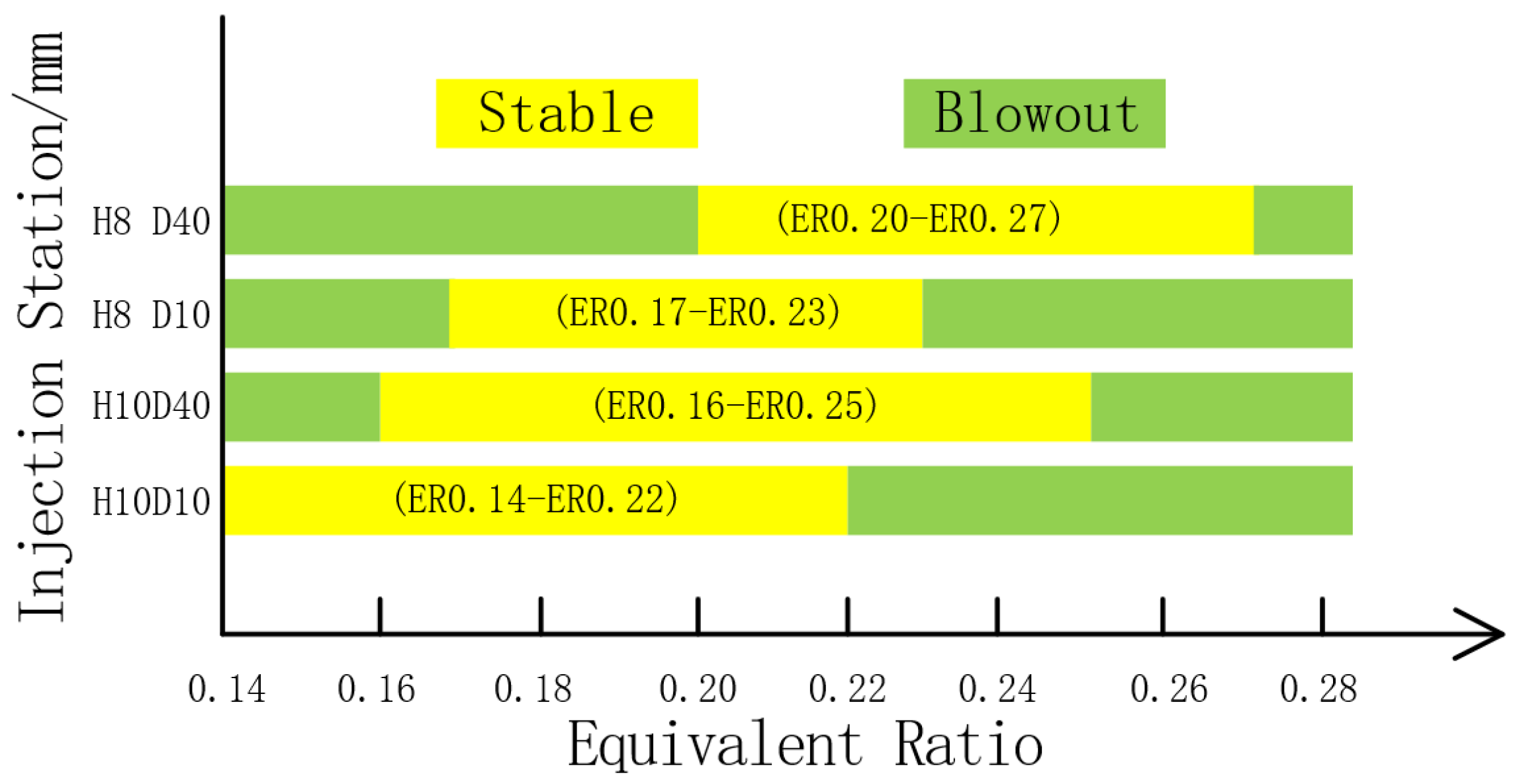
Figure 6 shows the flame stability limits for different injection distances and cavity rear-wall heights. The experiment found that the conventional cavity and the shorter injection distance can effectively broaden the lower limit of the global equivalence ratio for the combustor operation, but the rear-wall-expansion cavity and the longer injection distance can improve the upper limit of the global equivalence ratio for the combustor operation. It is necessary to note that the size of the cavity used in this paper is relatively small in order to facilitate optical observation, thus the flame stability limit of the combustor is narrow. If the overall equivalence ratio is further reduced or increased beyond the flame stability limit given in Figure 6, flame blowoff or unsuccessful ignition will occur.
High-speed photography is a kind of high-repetition frequency diagnosis technology. It can provide data support for studying the combustion mechanism and dynamic evolution process of flame morphology in supersonic flow fields through high-frequency, short-time recording. With reasonable image-processing capacity, high-speed photography is a popular means of flow field observation in supersonic combustion experiments.
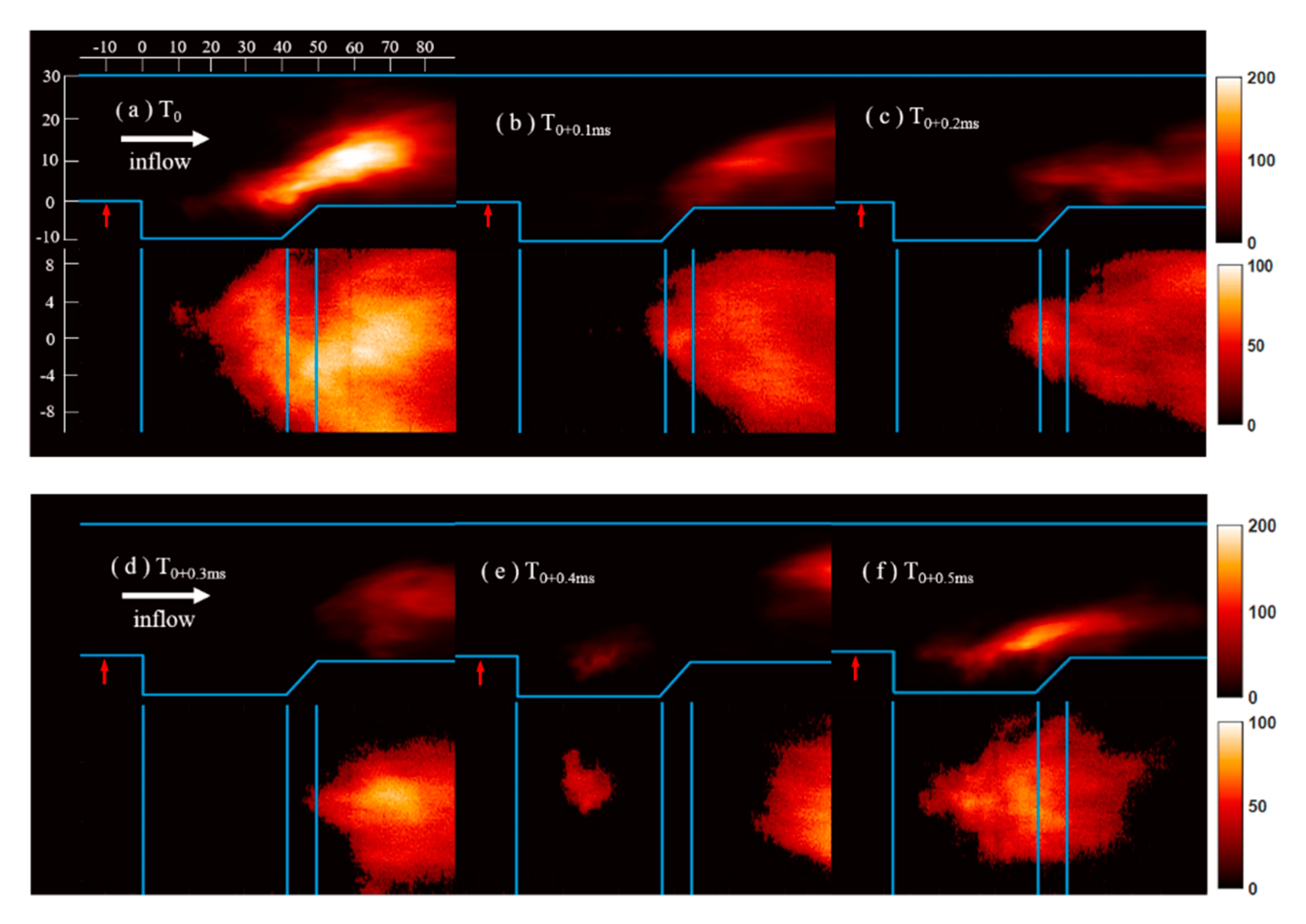
Figure 7 shows the flame blowoff and flashback process of case H8D10ER0.23 near blowoff conditions, including both top and side views at the same instant. The flame flashback process lasts about 0.6 ms, during which the cavity-stabilized flame is near blowoff and then reignited. The flame front is stabilized in the cavity shear layer at the initial instant T0. The CH* distribution indicates that strong combustion takes place near the cavity trailing edge and then spreads into the mainstream, leading to intense heat release. Due to the influence of the high-speed mainstream and the excessive consumption of the fuel inside the cavity, the flow field in the cavity cannot support the stabilization of the flame front at T0+0.1ms and T0+0.2ms, and the flame is blown downstream of the cavity. The fuel in the mainstream cannot be effectively ignited due to the disappearance of the flame front. The range of the heat-release zone decreases obviously. At time t0+0.3ms, as the flame front is far away from the low-speed region in the cavity, the combustor is in a state of the near blowoff. No flame is found in the cavity, and the fuel in the shear layer is reaccumulated with the supplement of the transverse injection. Then, the flame in the cavity shear-layer is reignited by the internal high-temperature fluid and active group at T0+0.4ms. The shear-layer flame develops and is finally established at T0+0.5ms. At the same time, it can be found from Figure 7e,f that the original flame downstream of the cavity is gradually blown off.
The flame oscillation frequency will be more intense with further increases in equivalence ratio. However, the fuel in the cavity shear layer cannot be reignited if the original flame is blown downstream of the cavity. Instead, with the original flame gradually disappears from the observation window, the combustor finally flames out. The reason for this phenomenon may be that the increased penetration depth of fuel leads the flame further into the mainstream, so the flame is more influenced by the high-momentum inflow. Meanwhile, the fuel-rich section of the cavity shear layer is lengthened, and the internal flow field environment is not conducive to flame stabilization, so the flame oscillation will be more intense. At the same time, the temperature and active groups inside the flow field of the cavity have not accumulated well due to the strong flame oscillation, because the fuel in the cavity cannot be reignited. Therefore, the flame is blown off under the action of several coupling factors.
In practice, there will be different requirements for engine combustor thrust due to different working conditions, and the phenomenon of different flame stability limits will have certain reference significance to broaden the working boundary of the engine.

3.2. Effects of Transverse Injection Distance

The experiment finds that changing the injection distance will cause a great influence on flame stability limits, chemical reaction-zone distribution, and flame oscillation. Different image-processing technology will be adopted in this section to capture the flame dynamics.
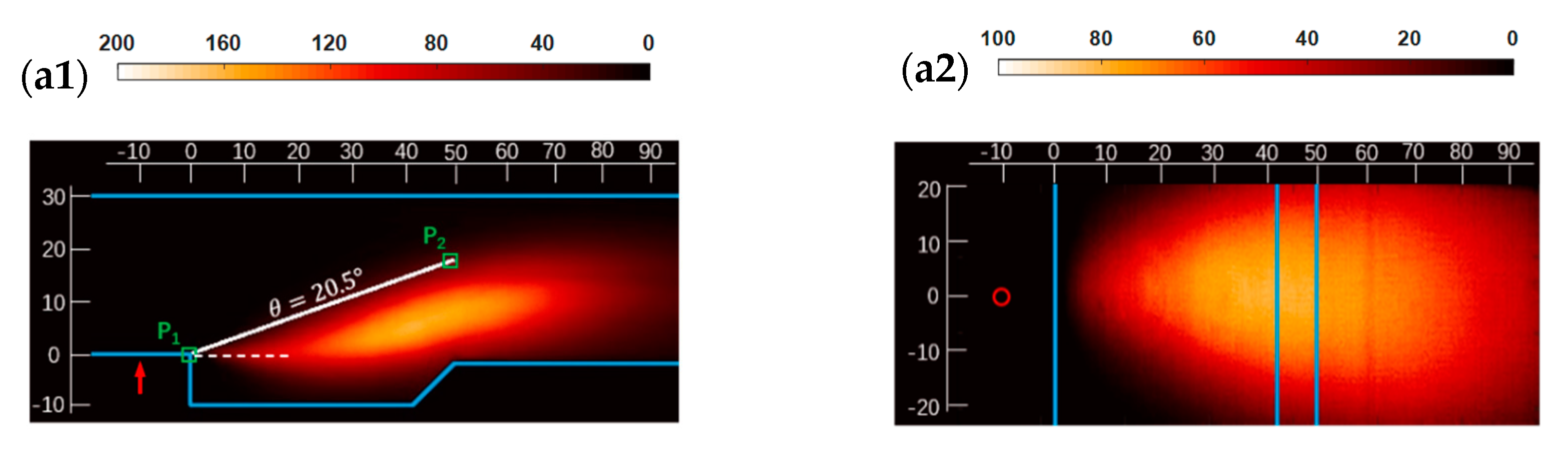
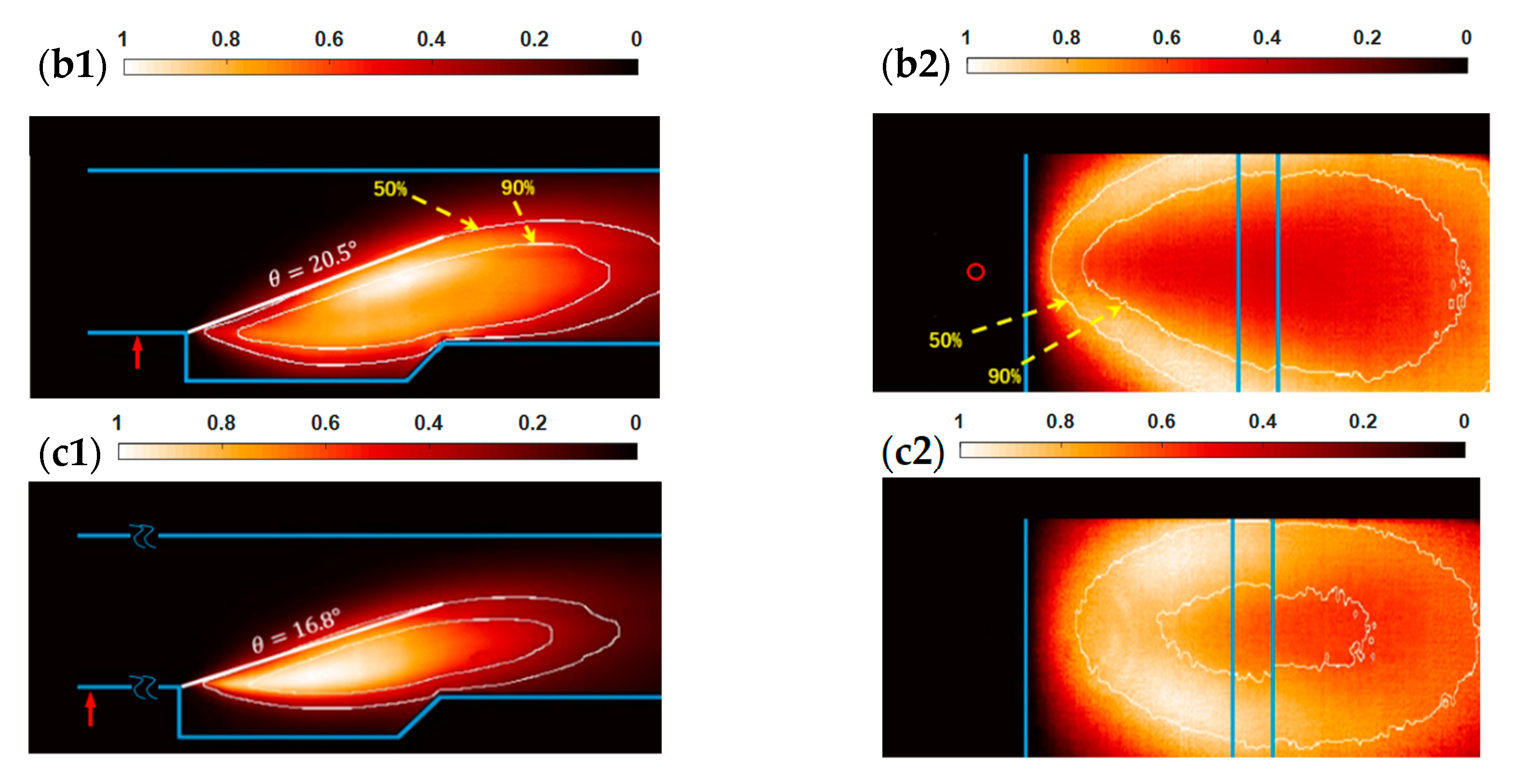
Figure 8 shows the time-averaged spontaneous emission images and standard deviation images of the CH* signal. In order to improve the contrast of image, the standard deviation image is normalized by the global highest value. White lines indicate 50% and 90% probability contour lines of the flame image. In the present study, the processing method of flame-probability definition is to select 5000 CH* spontaneous emission images, and each image is binarized based on intensity threshold. Then, the image is superimposed and averaged to obtain the flame-probability image. Finally, different probability contour lines are extracted and superimposed on the standard deviation images. The flame-probability image matrix has values ranging from 0 to 1, where 1 means that the flame of the index point always exists and 0.5 means that there is a 50% probability of flame appearing in 5000 pictures. The flame-probability images emphasize the location of the flame signal, but weaken the intensity information of chemical reaction.
Because the upper boundary of flame signal area is often not a straight line, it is difficult to achieve a unified standard under different conditions by manually adding the flame-propagation angle. Therefore, the following method is adopted to define the flame-propagation angle. First, determine the positions of P1 and P2, where P1 is the cavity leading edge and P2 is the index point of the 50% probability contour line of the pixel column where the cavity trailing edge is located. Then, the angle between the extracted straight line and the horizontal line is the flame-propagation angle defined in this paper. Based on the above method, it can be found that the extracted straight line is basically tangential to the upper edge of the flame, which means that the upper edge of the flame is not a straight line. The flame-propagation angle can also be estimated through the flame-probability image.
Figure 8a shows time-averaged CH* spontaneous emission images from different perspectives. The flame structure is similar within the working condition range of the experiment, so case H8D10ER0.2 is selected as an example. The side-view results show that the flame front is anchoring at the front of the cavity shear layer and gradually spreads to the interior of the cavity and the mainstream. The flame-propagation angle is 20.5°, and the flame present is in cavity shear-layer stabilized combustion mode [15]. The top-view results show that under the condition of single injector, the flame in the cavity shear-layer stabilized mode concentrates downstream of the jet and spreads to the side wall gradually. This means that chemical reaction intensity decreases gradually from the center to both sides.
The standard deviation images of CH* signal are shown in Figure 8b,c, which represent the fluctuation of CH* signal at different positions in the combustor. The distribution of normalized signals is similar when the rear-wall height or equivalence ratio is changed at the same injection distance. H8D10ER0.2 and H8D10ER0.2 are selected to compare the impact of injection distance on flame oscillation characteristics. Figure 8b1,c1 show that under the condition of single injector, the high-brightness strip is mainly in the 90% probability contour, but Figure 8b2,c2 show that the high-brightness strip is within the 50% and 90% probability contour envelope. The difference is mainly because the flame images obtained from each perspective are the two-dimensional integral results of the flame spatial structure. Therefore, a more practical conclusion can be obtained by superposition of two perspectives: the high-brightness strip is wrapped in 50% and 90% probability contour lines on both sides of the flame cone in 3D space, i.e., this part of the flame often disappears due to oscillation. The standard deviation inside the flame cone is only about half of the strongest point. This is because under the condition of single injector, the fuel is mainly concentrated near the central section, so the flame stabilization of this part is higher than that of the two sides. By comparing the flame standard deviation images of Figure 8b,c at different injection distances, the following two conclusions can be obtained. (1) Under the condition of short injection distance, the flame oscillation intensity near the shear layer is obviously lower than the mainstream; however, under the condition of long distance injection, the strongest oscillation point is mainly concentrated near the leading edge of the shear layer and gradually expands to the main flow and downstream of the shear layer. The main reason for the difference may be that the flame-propagation angle is smaller in the long-distance injection scheme, which leads to lower flame height in the mainstream, so the mainstream has a relatively small effect on the flame. (2) At the same equivalence ratio, with the increase in injection distance, the wrapping range of the two flame-probability contour lines will obviously shrink. The height of the flame in the mainstream decreases and the flame-propagation angle decreases. The flame-propagation angle decreases by 18% from H8D10ER0.2 to H8D40ER0.2. The results indicate that the short-distance condition can effectively increase the chemical reaction area and make the fuel ignite fully.
It can be found from the time-averaged CH* spontaneous emission image in Figure 8a that the range wrapped by the flame 90% probability contour line basically coincides with the high CH* signal area. This indicates that this region is not only the stable existence zone of flame but also the strong heat-release zone of shear-layer flame.
In order to further analyze the effect of injection distance on the reaction-zone distribution during the stable combustion process, the location of the reaction center is extracted from the flame image. First, the flame images from two perspectives are transformed into grayscale images, then the position coordinates (xr, yr and zr) of the reaction center area are calculated by the brightness weighted-average method. The origin of coordinates is taken from the intersection of the spanwise central section and the cavity leading edge. The values xr, yr, and zr are streamwise, spanwise, and longitudinal coordinates, respectively, which can be calculated by Equation (6):
x r = i = 1 n ( x i I i ) / i = 1 n I i + j = 1 m ( x j I j ) / j = 1 m I j 2 y r = j = 1 m ( y j I j ) / j = 1 m I j z r = i = 1 n ( z i I i ) / i = 1 n I i
where xi, xj, yj, and zi are the image matrix index coordinates obtained from the top view and side view at the same time. Ii and Ij are the signal intensity of image matrix index points from two perspectives. The streamwise coordinate X is shared by two perspectives. However, due to the difference in the direction of spatial integration, there is a slight deviation in the weighted average of the two coordinates, so the coordinates of two directions are taken for averaging. The values yj and zi are obtained separately from the top and side views, respectively.
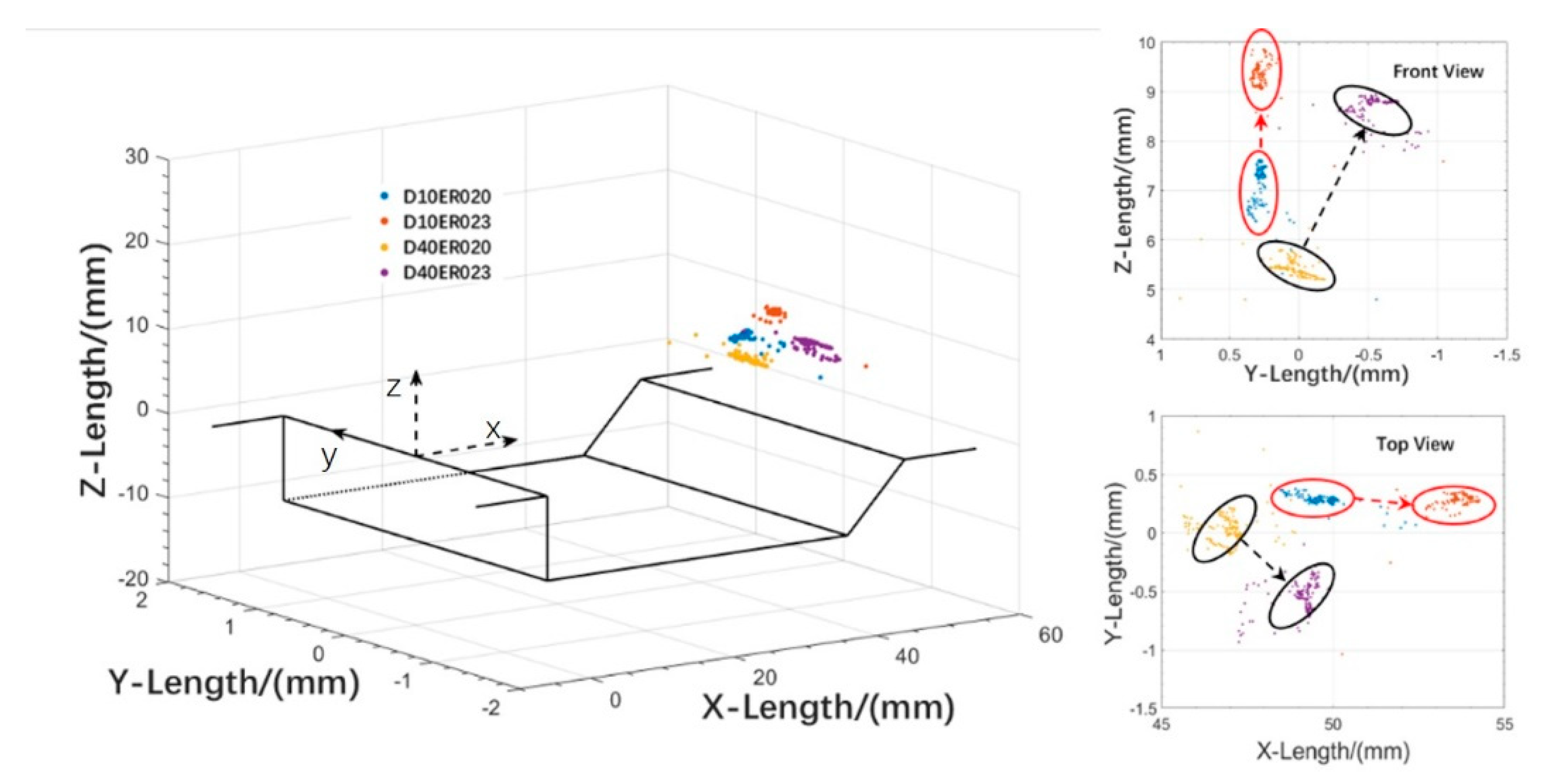
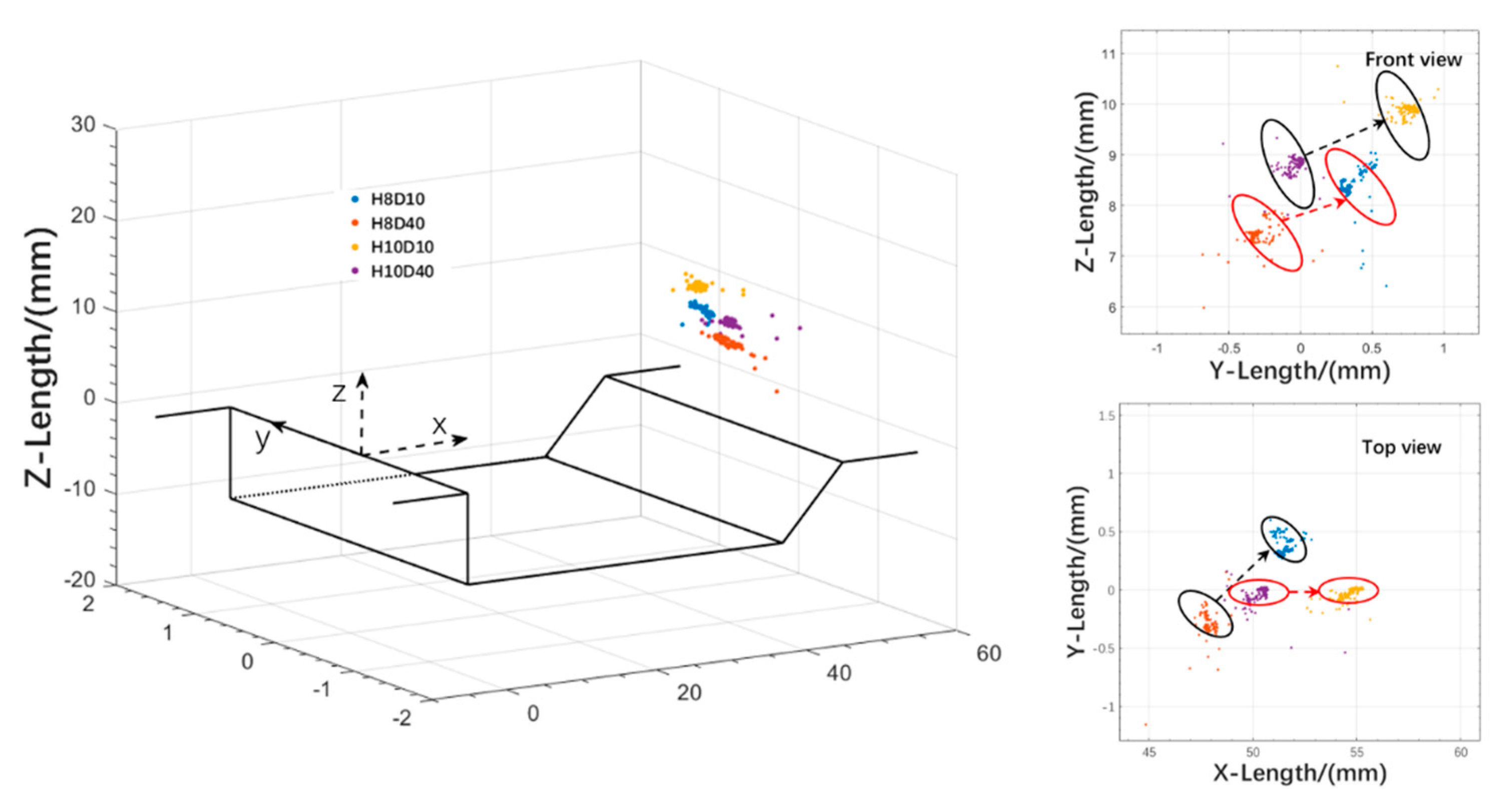
Figure 9 shows the calculation results of 150 CH* spontaneous emission images for 15 ms after the spark plug is closed, each data point corresponding to an image. The time-evolution information of the reaction center position is given from three- and two-dimensional space. The high-frequency distribution region of the flame reaction center position of the same injection scheme is marked using the same color marker area. It can be found that the position of the flame reaction center is slightly different with different equivalence ratios, but the overall distribution is near y = 0, indicating that the flame mainly oscillates near the downstream of the injector. This shows that the downstream of injector is more suitable for stable combustion. As the equivalence ratio increases, the central area of the flame will move backward along the flow direction (X) and further rise to make the flame deeper into the mainstream direction (Z). The position of the reaction center of case H8D10ER0.23 even exceeds the rear wall of the cavity. Combined with the flame-probability contour lines in Figure 8b,c, it can be seen that under the condition of stable combustion, the flame reaction area of short-distance injection is more widely distributed and deeper into the mainstream. Combined with the flame-probability contour lines in Figure 8b,c, it can be seen that the flame reaction area is more widely distributed and deeper into the mainstream under the condition of short-distance injection.
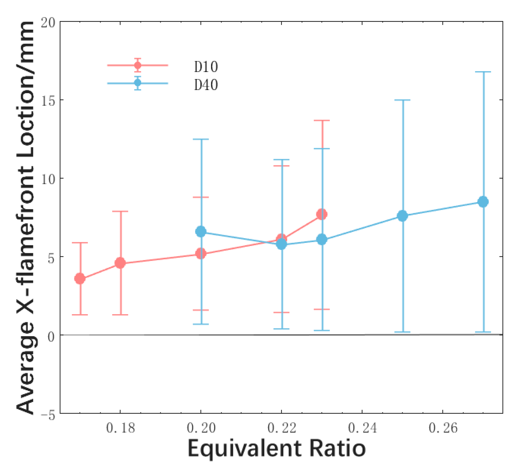
In order to study the differences in flame stabilization between different injection schemes, Figure 10 shows the distribution of average flame front position and its standard deviation under different equivalence ratios and two injection distances. The rear-wall-expansion cavity is selected as the flameholder, and the black solid line represents the flow direction position of the cavity leading edge. It can be found that the flame front position oscillates violently when the combustion is in the cavity shear-layer stabilized mode and gradually moves away from the cavity leading edge with increased equivalence ratio. This is mainly because the interaction between the fuel jet and the cavity shear layer increases with the increase in injection pressure, resulting in the increase of the unsteady characteristics of the shear layer and flame front oscillation [24]. At the same time, the mass of the fuel entering the cavity shear layer increases, and the rich combustion area of the initial section in the shear layer becomes longer. The local fuel–air equivalence ratio is conducive to the downstream movement of the flame front. However, the long-distance injection scheme has a singularity in case H8D40ER0.2. The average value of the flame front position is bigger than in case H8D40ER0.22, and there is an inverse growth. This may be because the interaction between the fuel jet and the cavity shear layer will be reduced when the injection distance increases. Therefore, when the global equivalence ratio is low, the long-distance injection will make it easier for the flame to reach blowoff, which leads to the flame front moving downstream and the flame oscillation increasing. However, such singularity does not appear in the short-distance injection scheme, indicating that when the global equivalence ratio is reduced to reach the flame stability limit of the combustor under the short-distance injection scheme, it is not the lean blowoff limit of the engine. Instead, under the conditions of this experiment, the difficulty of ignition in the short-distance injection scheme at low equivalence ratio is greater than that of flame stabilization.
As the equivalence ratio further increases, the distance between the flame front and the cavity leading edge of case H8D10 will exceed that of H8D40. The flame front position and its standard deviation in H8D10 reach a peak at ER0.23, which is the flame stability limit of the short-distance injection scheme. The global equivalence ratio can be further improved in case H8D40, and the flame front position and its standard deviation reach a peak at the ER0.27, which is the flame stability limit of the long-distance injection scheme. The possible reason for the different flame stability limits of the scramjet combustor with different injection schemes is that: the interaction between the fuel jet and the cavity shear layer is weakened under the long-distance injection scheme and the global equivalence ratio requirement for the cavity shear layer to reach the combustion rich blowoff limit is improved. Generally speaking, the stability of the flame front along the flow direction of the short-distance injection scheme is higher than that of the long-distance injection scheme at low equivalence ratio, but the opposite is true at high equivalence ratio. This difference in flame stabilization is also the reason for the different flame stability limits of the combustor at different injection distances.
The injection distance will cause a significant influence on flame stabilization. The long-distance injection scheme can achieve a higher combustor equivalence ratio upper limit. However, since the short-distance injection scheme can effectively improve flame stabilization and combustion efficiency at medium and low equivalence ratios, the combustor can be properly adjusted as per injection scheme in actual work, to improve the engine-specific impulse and thrust.

3.3. Effects of Cavity Rear-Wall Height

The experiment finds that the change of the cavity rear-wall height will have little influence on flame oscillation compared with injection distance. This indicates that the fuel-mixing degree plays a leading role in the spatial oscillation of reaction position, which is mainly decided by the injection scheme, but they both have great influence on flame stability limits, flame spatial distribution, and combustion heat release.
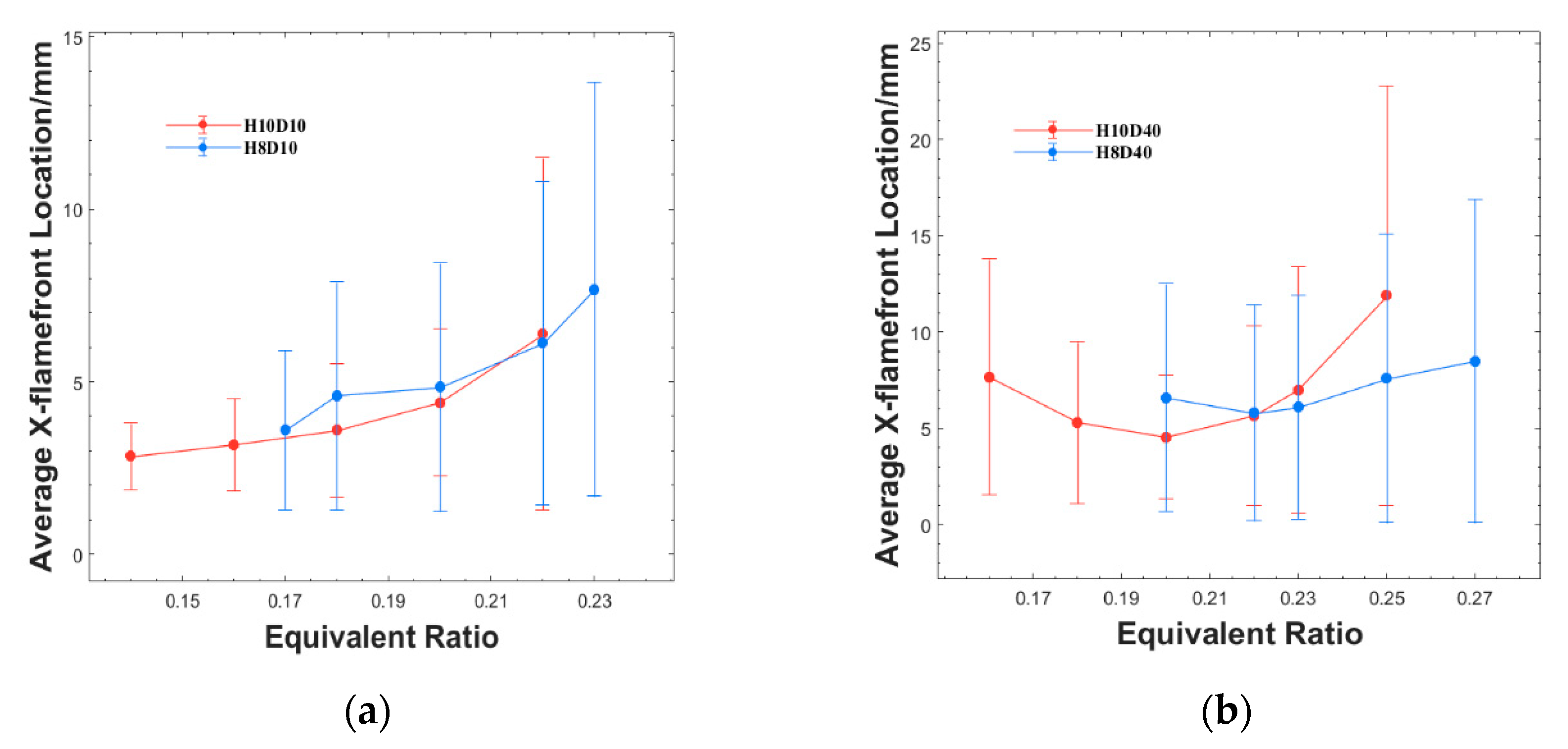
In order to study why the flame stability limit is different under different rear-wall heights, Figure 11 shows the distribution of average flame front position and its standard deviation under different cavity rear-wall heights and equivalence ratios. It can be found that under the same injection scheme, the distribution of the average flame front position and its standard deviation has the same trend. Figure 11a shows that under the short-distance injection scheme, the average flame front position gradually moves away from the cavity leading edge with the increase in equivalence ratio. The stable position of the flame front of the H10 cavity is closer to the cavity leading edge and the flame oscillation is smaller, indicating that the combustion is more stable at lower equivalence ratio. Figure 11b shows that under the long-distance injection scheme, the average flame front position and the standard deviation of the two types of cavity combustor show a trend of first decreasing and then increasing. However, as the equivalence ratio increases, the average flame front position of the conventional cavity will gradually exceed that of the rear-wall-expansion cavity under different injection schemes. This is because the increase of rear-wall height leads to enhanced interaction between the shear layer and the jet wake, resulting in enhanced mass exchange inside and outside the cavity. Therefore, the lean blowoff limit of flame can be reduced in conventional cavity, while the rich blowoff limit can be easily reached when the global equivalence ratio is high.
By comparing the position changes of flame front in conditions of different injection distances in Figure 11a,b, it can be found that under the same injection scheme but different cavity configurations, the position of the flame front has the same trend as the change in equivalence ratios. Under the experimental conditions of this paper, it is not the lean blowoff limit in the combustor when the short-distance injection condition reaches the near-blowoff condition. This is mainly due to the difficulty of ignition in cavity being greater than that of combustor flame stabilization, which is related to the discharge power of the spark plug and the flow field environment inside the cavity.
For the distribution difference of reaction centers under different cavity rear-wall height, Figure 12 shows the dynamic data of the reaction center location for different cases at ER = 0.22. It can be found that the location of the flame reaction center is slightly different. Under the same injection condition, with increased rear-wall height, the flame center will be further away from the cavity along the X axis and further into the mainstream along the Z axis. In other words, the heat-release area in the combustor is larger with increased rear-wall height. It will strengthen the ignition of the fuel with high penetration depth in the mainstream, thus improving the combustion efficiency of the fuel and improving the specific impulse of the combustor.
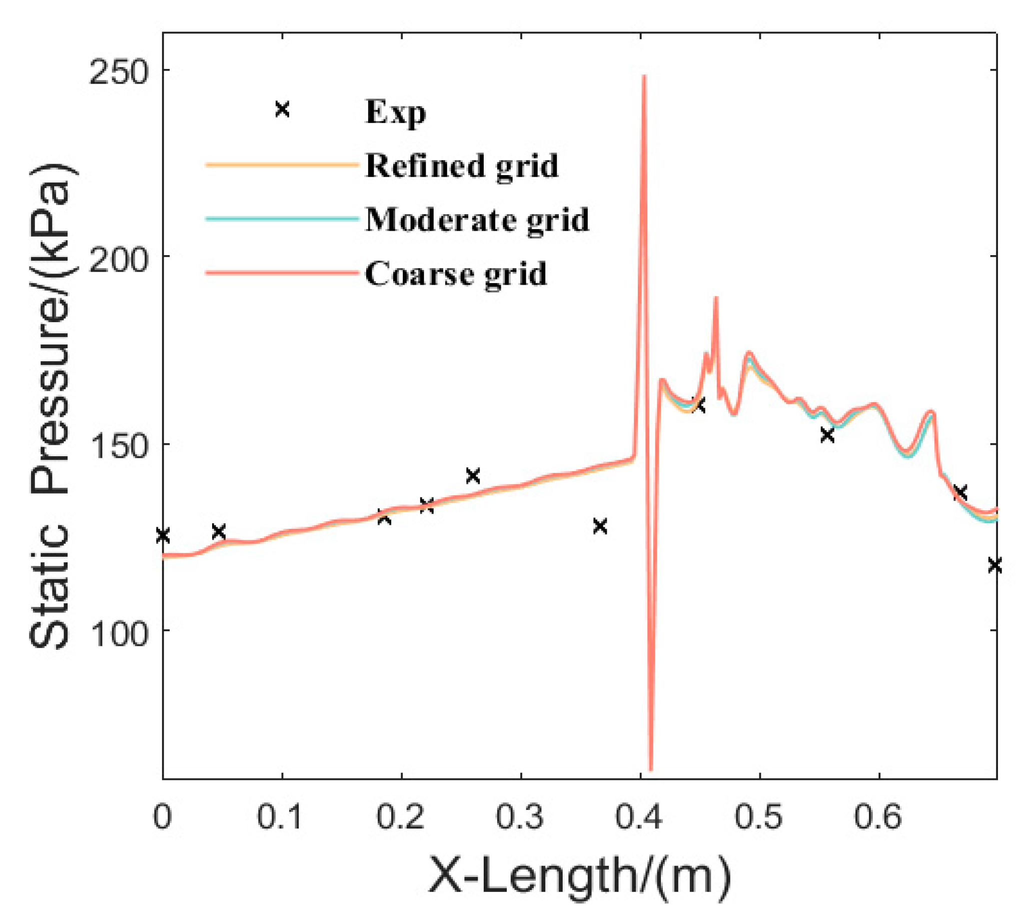
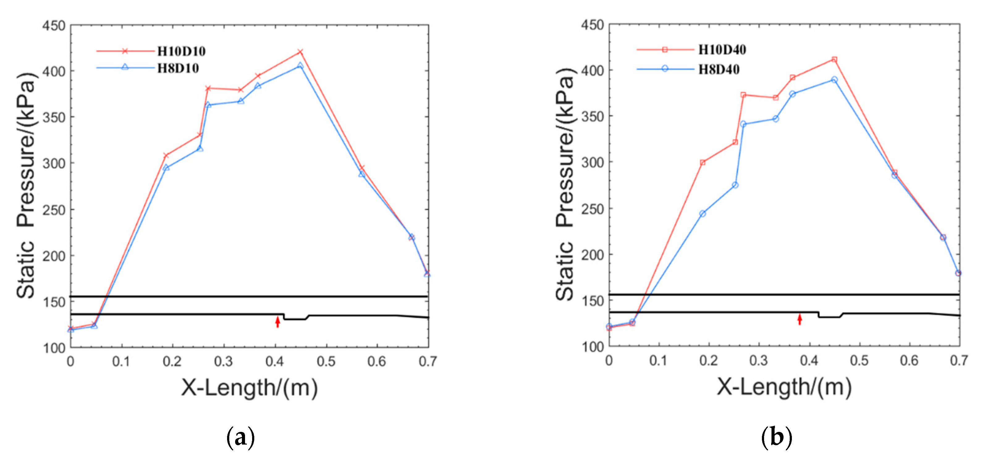
Figure 13a,b show the wall-pressure distribution at different rear-wall heights and the same injection distance when the equivalence ratio is 0.22. The isolator used is extended straight and has weak resistance to back pressure, so the back pressure causes the boundary-layer separation at the outlet of the isolator, which causes the pressure to transfer forward obviously. It can be found that the combustion heat release mainly occurs near the cavity under different working conditions. The peak pressure is located near the rear wall of the cavity, and then the pressure drops sharply in the downstream expansion section of the cavity. With the increase in rear-wall height, the wall-pressure is higher under the same injection condition. This is consistent with the result of the reaction center distribution shown in Figure 12. When the combustion is in the cavity shear-layer stabilization mode, the reaction zone penetrating into the mainstream can effectively ignite the fuel there, so as to improve combustion efficiency and enhance heat release. The combustion pressure ratios of different cases are extracted, and as listed in Table 2, it is found that the traditional cavity can effectively increase the pressure distribution in the combustor at different injection distances. In other words, the conventional cavity can effectively enhance combustion and heat release under stable combustion conditions.
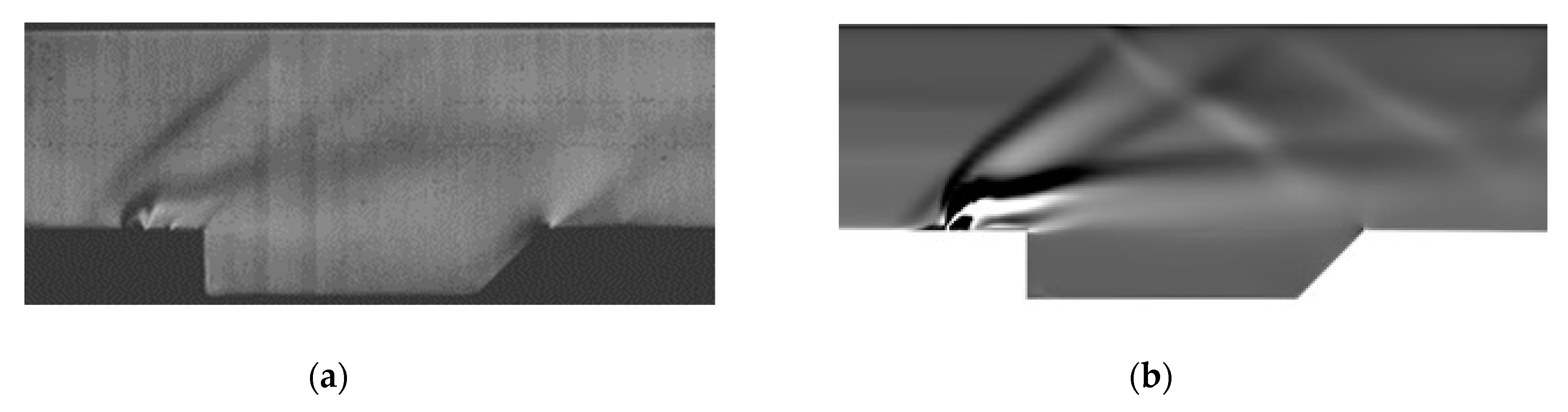
Figure 14 shows the time-averaged schlieren results of the experiments and the numerical calculation in the H10D10ER0.22 scheme. Notably, an oblique shock appears between the fuel injection and the front wall of the cavity in the experimental results. This shock comes from the installation of the replaceable cavity/injection section of the combustor, which is usually unavoidable in scramjet experiments and may have some influences on the flow around the jet and cavity, such as slightly changing the temperature and pressure of the flow approaching the jet and cavity, slightly distorting the cavity shear layer, etc. Though these influences deserve further investigation, we think they do not affect the main conclusions obtained in the present study.
Two schlieren results show the same basic flow field structure. The barrel shock, Mach disk, bow shock, separation shock, reflection shock, and slip line are captured by numerical calculation, further proving that the numerical approach employed in this paper is suitable. In the experimental result, the structure of the bow shock is relatively clear. The position of the interaction point between the upper wall and the bow shock is basically the same as the numerical calculation result. However, obvious local shadows can be seen near the rear wall of the cavity in the experimental result, due to the local density gradient change caused by the impact of the mainstream on the rear wall of the cavity. This phenomenon is not reflected in the numerical calculation result. This is mainly because the experimental schlieren image is the two-dimensional integration result of the first derivative of the entire flow field density along the optical axis of the camera and numerical calculation shows only the schlieren results on the mid-span z/D = 0 plane. In this area, the fuel injection is an obstacle relative to the mainstream, which reduces the impact of the mainstream on the rear wall of the cavity.
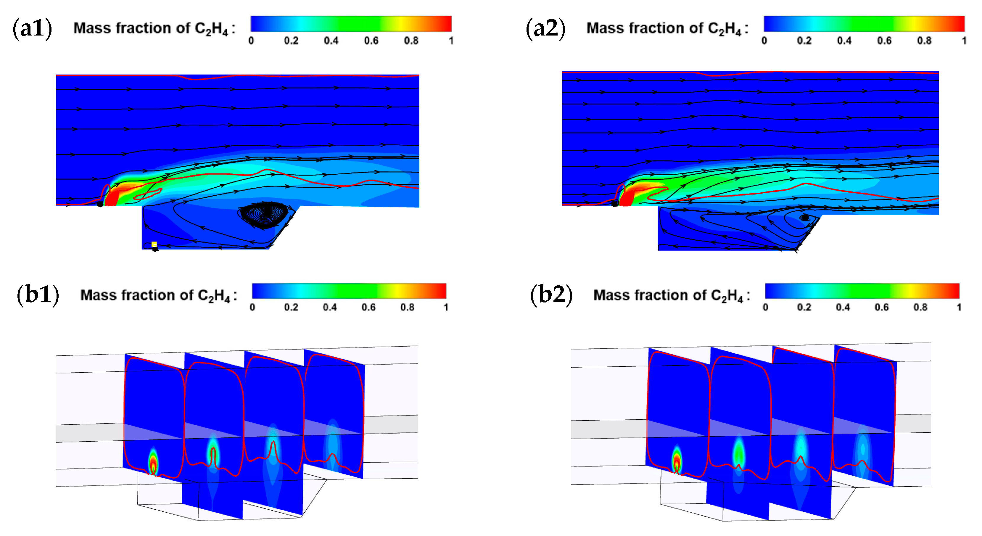
Figure 15 shows the calculated fuel distribution for different cavity rear-wall heights when the injection distance is 10 mm and the global equivalence ratio is 0.22. The solid red line represents the sonic line. Due to the impact of the cavity rear-wall expansion, the structure of the supersonic flow field changes greatly compared with the conventional cavity. This is because when the inflow flows through downstream of the cavity, it is equivalent to entering a larger flow channel. It can be found that the penetration depth of the fuel jet in the conventional cavity combustor (Figure 15a1) exceeds the center section of flow passage shown in Figure 15b1, but is not reached in the rear-wall-expansion cavity combustor shown in Figure 15b2. That explains the reason for the difference in the location of reaction center in different cavities.
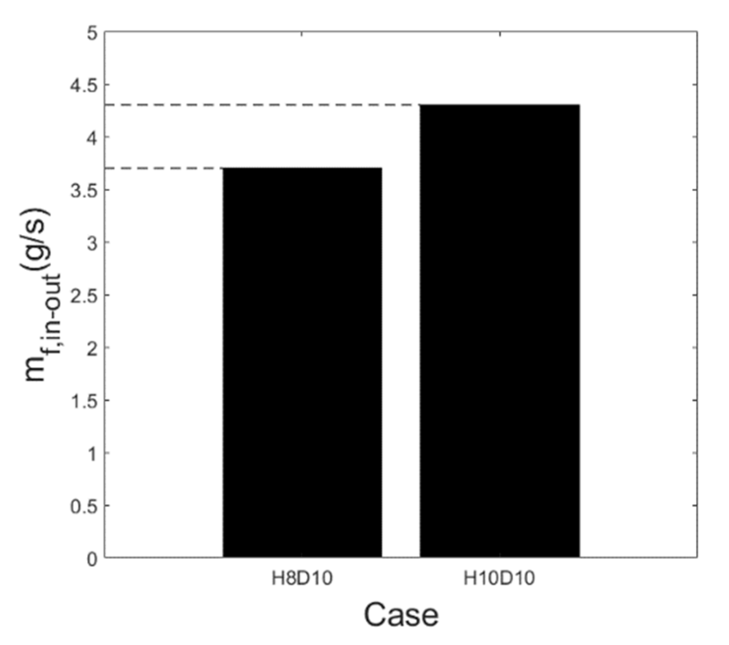
At the same time, it can be found that the sonic line of the rear-wall-expansion cavity is obviously decreased compared with that of the conventional cavity, indicating that the recirculation zone of the conventional cavity is larger and more fuel is wrapped in the range of the low-speed region. The fuel-entrainment rate shown in Figure 16, which is calculated by Equation (2), represents the fuel-entrainment capacity of the cavity flameholder, where A a c v is the projected area of the cavity lip section on the transverse section, ν is the transverse velocity, and Y C 2 H 4 is the local ethylene fuel mass fraction. The fuel-entrainment rate at the lip section of conventional cavity H10 is the highest, up to 4.3 g/s under current conditions, 16.2% higher than that of rear-wall-expansion cavity H8. This indicates that more fuel is entrained into the conventional cavity at the same injection pressure. Therefore, the conventional cavity can effectively reduce the lower equivalence ratio bound of flame stabilization; however, it leads to flame blowoff easily due to local rich combustion under the high injection pressure.
m f . i n o u t = = = A c a v ρ | ν | Y C 2 H 4 d A a c v

4. Conclusions

In this paper, the characteristics of supersonic combustion with ethylene injection upstream of the cavity are experimentally and numerically investigated under Ma2.52 supersonic flow conditions. The technologies of high-speed photography, pressure scan system, and image processing are used in the experiment. The effects of injection distance and cavity rear-wall height on flame stabilization and flame oscillation are revealed. The major conclusions are as follows.
1. The combustor exhibits a typical cavity shear-layer flame stabilization mode under the present experimental conditions. The flame stability limit is obtained by changing the fuel equivalence ratio gradually. The conventional cavity and the short injection distance can effectively broaden the lower limit of global equivalence ratio for the combustor, but the rear-wall-expansion cavity and the longer injection distance can improve the upper limit of the global equivalence ratio for the combustor.
2. Under the condition of a single injector upstream of the cavity, the flame oscillation area is mainly distributed on both sides of the flame cone. The strongest oscillation points are mainly concentrated in the mainstream zone under the short-distance injection. As the injection distance increases, the strong oscillation zone is more concentrated near the shear layer and gradually extends backward, which does not change obviously when the cavity rear-wall height is changed. In other words, it is found that the flame oscillation distribution of the shear-layer flame is not related to the cavity rear-wall height, but is mainly related to the injection distance.
3. Under the same cavity configuration, the lean blowoff limit decreases with decreased injection distance, but the flame will be more unstable at the high equivalence ratio, easily leading to flame blowoff. At the same equivalence ratio, the short-distance injection scheme can effectively enhance combustion. Therefore, under the medium and low equivalence ratio conditions, the injection distance can be appropriately shortened to extend the lean blowoff limit of the combustor and improve the specific impulse of the scramjet combustor, but when the scramjet needs more thrust in practice, the injection distance can be appropriately increased to obtain a higher thrust upper limit.
4. Under the same injection distance, the lean blowoff limit and combustion intensity increase with increased cavity rear-wall height. However, due to the improvement in the interaction between jet and cavity shear layer, the fuel entrained in and out of the cavity becomes stronger. This will decrease the rich blowoff limit of the combustor.

Author Contributions

Writing—original draft preparation, Z.H.; supervision, H.W.; writing—review and editing, F.L.; visualization, Y.T.; formal analysis, M.W.; resources, J.Z. All authors have read and agreed to the published version of the manuscript.

Funding

This work was supported by the National Natural Science Foundation of China (NSFC) (Grant nos.12172379, 12002381) and the Scientific Research Plan of the National University of Defense Technology in 2019 (ZK19-02).

Data Availability Statement

Not applicable.

Conflicts of Interest

The authors declare no conflict of interest.

References

  1. Huang, W. Transverse jet in supersonic crossflows. Aerosp. Sci. Technol. 2016, 50, 183–195. [Google Scholar] [CrossRef]
  2. Wang, Z.; Wang, H.; Sun, M. Review of cavity-stabilized combustion for scramjet applications. Proc. Inst. Mech. Eng. Part G J. Aerosp. Eng. 2014, 228, 2718–2735. [Google Scholar] [CrossRef]
  3. Yu, K.H.; Schadow, K.C. Cavity-actuated supersonic mixing and combustion control. Combust. Flame 1994, 99, 295–301. [Google Scholar] [CrossRef]
  4. Li, X.; Lei, Q.; Zhao, X.; Fan, W.; Chen, S.; Chen, L.; Tian, Y.; Zhou, Q. Combustion Characteristics of a Supersonic Combustor with a Large Cavity Length-to-Depth Ratio. Aerospace 2022, 9, 214. [Google Scholar] [CrossRef]
  5. Li, Z.; Gu, H. Investigation for Effects of Jet Scale on Flame Stabilization in Scramjet Combustor. Energies 2022, 15, 3790. [Google Scholar] [CrossRef]
  6. Jeong, E.; O’Byrne, S.; Jeung, I.S.; Houwing, A.F.P. The effect of fuel injection location on supersonic hydrogen combustion in a cavity-based model scramjet combustor. Energies 2020, 13, 193. [Google Scholar] [CrossRef]
  7. Kato, N.; Im, S. Flame dynamics under various backpressures in a model scramjet with and without a cavity flameholder. Proc. Combust. Inst. 2021, 38, 3861–3868. [Google Scholar] [CrossRef]
  8. Wang, H.; Wang, Z.; Sun, M.; Wu, H. Combustion modes of hydrogen jet combustion in a cavity-based supersonic combustor. Int. J. Hydrogen Energy 2013, 38, 12078–12089. [Google Scholar] [CrossRef]
  9. Li, F.; Sun, M.; Yang, Y.; Wang, H.; Sun, Y.; Li, F.; Liang, C. Mixed Flow Field Structure Analysis of Transverse Injection Upstream of the Cavity based on POD and DMD. In Proceedings of the 11th National Conference on Fluid Mechanics, Shenzhen, China, 4 December 2020. (In Chinese). [Google Scholar]
  10. Wang, Y.; Wang, Z.; Sun, M.; Wang, H.; Cai, Z. Effects of fueling distance on combustion stabilization modes in a cavity-based scramjet combustor. Acta Astronaut. 2019, 155, 23–32. [Google Scholar] [CrossRef]
  11. Li, F.; Wang, H.; Sun, M.; Cai, Z.; Sun, Y.; Huang, Y.; Zhu, J. Experimental study on cavity flame stabilization characteristics of two optimized combined fuel injection schemes. J. Soild Rocket. Technol. 2021, 44, 152–159. (In Chinese) [Google Scholar]
  12. Wang, Z. Flame Stabilization and Propagation in Supersonic Airflow; Science Press: Beijing, China, 2015. (In Chinese) [Google Scholar]
  13. Zhang, J.; Chang, J.; Wang, Z.A.; Gao, L.; Bao, W. Flame propagation and flashback characteristics in a kerosene fueled supersonic combustor equipped with strut/wall combined fuel injectors. Aerosp. Sci. Technol. 2019, 93, 105303. [Google Scholar] [CrossRef]
  14. Wang, H.; Wang, Z.; Sun, M.; Qin, N. Combustion characteristics in a supersonic combustor with hydrogen injection upstream of cavity flameholder. Proc. Combust. Inst. 2013, 34, 2073–2082. [Google Scholar] [CrossRef]
  15. Micka, D.J.; Driscoll, J.F. Combustion characteristics of a dual-mode scramjet combustor with cavity flameholder. Proc. Combust. Inst. 2009, 32, 2397–2404. [Google Scholar] [CrossRef]
  16. Li, F.; Sun, M.; Cai, Z.; Sun, Y.; Li, F.; Zhang, J.; Zhu, J. Experimental study of flame stabilization in a single-side expansion scramjet combustor with different cavity length-to-depth ratios. Acta Astronaut. 2020, 173, 1–8. [Google Scholar] [CrossRef]
  17. Zhang, Y.-X.; Wang, Z.-G.; Sun, M.-B.; Yang, Y.-X.; Wang, H.-B. Hydrogen jet combustion in a scramjet combustor with the rearwall-expansion cavity. Acta Astronaut. 2018, 144, 181–192. [Google Scholar] [CrossRef]
  18. Cai, Z.; Yang, Y.; Sun, M.; Wang, Z. Experimental investigation on ignition schemes of a supersonic combustor with the rearwall-expansion cavity. Acta Astronaut. 2016, 123, 181–187. [Google Scholar] [CrossRef]
  19. Yang, Y.; Wang, Z.; Zhang, Y.; Sun, M.; Wang, H. Flame stabilization with a rearwall-expansion cavity in a supersonic combustor. Acta Astronaut. 2018, 152, 752–756. [Google Scholar] [CrossRef]
  20. Yang, Y. Study on Supersonic Flow Mode and Flame Stabilization Mechanism with Rearwall-Expansion Cavity. Master’s Thesis, National University of Defense Technology, Changsha, China, 2018. (In Chinese). [Google Scholar]
  21. Cai, Z.; Zhu, X.; Sun, M.; Wang, Z. Experimental study on the combustion process in a scramjet combustor with a rear-wall-expansion geometry. J. Aerosp. Eng. 2018, 31, 04018077. [Google Scholar] [CrossRef]
  22. Malhotra, A.; Vaidyanathan, A. Aft wall offset effects on open cavities in confined supersonic flow. Exp. Therm. Fluid Sci. 2016, 74, 411–428. [Google Scholar] [CrossRef]
  23. Kirik, J.W.; Goyne, C.P.; McDaniel, J.C.; Rockwell, R.D. Aerodynamics of Lean Blowout in a Premixed Dual-Mode Scramjet. J. Propuls. Power 2018, 34, 819–822. [Google Scholar] [CrossRef]
  24. Kirik, J.W.; Goyne, C.P.; McDaniel, J.C.; Rockwell, R.D.; Cantu, L.M.L.; Gallo, E.C.A.; Cutler, A.D. Aerodynamic Characterization of a Cavity Flameholder in a Premixed Dual-Mode Scramjet. J. Propuls. Power 2018, 34, 739–749. [Google Scholar] [CrossRef]
  25. Nilsson, T.; Carlsson, H.; Yu, R.; Bai, X.-S. Structures of turbulent premixed flames in the high Karlovitz number regime—DNS analysis. Fuel 2018, 216, 627–638. [Google Scholar] [CrossRef]
  26. Di Sarli, V.; Di Benedetto, A.; Russo, G. Large Eddy Simulation of transient premixed flame-vortex interactions in gas explosions. Chem. Eng. Sci. 2012, 71, 539–551. [Google Scholar] [CrossRef]
  27. Savard, B.; Bobbitt, B.; Blanquart, G. Structure of a high Karlovitz n-C7H16 premixed turbulent flame. Proc. Combust. Inst. 2015, 35, 1377–1384. [Google Scholar] [CrossRef]
  28. Rasmussen, C.C.; Driscoll, J.F.; Hsu, K.-Y.; Donbar, J.M.; Gruber, M.R.; Campbell, C.D. Stability limits of cavity-stabilized flames in supersonic flow. Proc. Combust. Inst. 2005, 30, 2825–2833. [Google Scholar] [CrossRef]
  29. Owens, M.G.; Tehranian, S.; Segal, C.; Vinogradov, V.A. Flame-holding configurations for kerosene combustion in a Mach 1.8 airflow. J. Propuls. Power 2015, 14, 456–461. [Google Scholar] [CrossRef]
  30. Wang, Y.H.; Song, W.Y. Experimental investigation of influence factors on flame holding in a supersonic combustor. Aerosp. Sci. Technol. 2019, 85, 180–186. [Google Scholar] [CrossRef]
  31. Wang, H.; Song, X.; Li, L.; Huang, Y.; Sun, M. Lean blowoff behavior of cavity-stabilized flames in a supersonic combustor. Aerosp. Sci. Technol. 2021, 109, 106427. [Google Scholar] [CrossRef]
  32. Cai, Z.; Wang, Z.; Sun, M.; Bai, X.S. Effect of combustor geometry and fuel injection scheme on the combustion process in a supersonic flow. Acta Astronaut. 2016, 129, 44–51. [Google Scholar] [CrossRef]
  33. Du, Z.B.; Huang, W.; Yan, L.; Li, S.B. Reynolds-average Navier-Stokes study of steady and pulsed gaseous jets with different periods for the shock-induced combustion ramjet engine. Phys. Fluids 2019, 31, 055107. [Google Scholar]
  34. Menter, F.R. Two-equation eddy-viscosity turbulence models for engineering applications. AIAA J. 1994, 32, 1598–1605. [Google Scholar] [CrossRef]
  35. Bardina, J.E.; Huang, P.G.; Coakley, T.J. Turbulence modeling validation, testing, and development. NASA Tech. Memo. 1997, 110446. [Google Scholar]
  36. Huang, W.; Liu, W.D.; Li, S.B.; Xia, Z.X.; Liu, J.; Wang, Z.G. Influences of the turbulence model and the slot width on the transverse slot injection flow field in supersonic flows. Acta Astronaut. 2012, 73, 1–9. [Google Scholar] [CrossRef]
  37. Song, X.; Wang, H.; Sun, M.; Cai, Z.; Liu, C.; Yu, J. Mixing and combustion characteristics in a cavity-based supersonic combustor with different injection schemes. Acta Astronaut. 2019, 159, 584–592. [Google Scholar] [CrossRef]
  38. Li, L.-Q.; Huang, W.; Yan, L.; Zhao, Z.-T.; Liao, L. Mixing enhancement and penetration improvement induced by pulsed gaseous jet and a vortex generator in supersonic flows. Int. J. Hydrogen Energy 2017, 42, 19318–19330. [Google Scholar] [CrossRef]
  39. Li, L.; Huang, W.; Yan, L.; Li, S.-B. Parametric effect on the mixing of the combination of a hydrogen porthole with an air porthole in transverse gaseous injection flow fields. Acta Astronaut. 2017, 139, 435–448. [Google Scholar] [CrossRef]
Figure 1. Model scramjet combustor.
Aerospace 09 00566 g001
Figure 2. Spark-ignition plug.
Aerospace 09 00566 g002
Figure 3. Schematic of the computational combustor with a cavity.
Aerospace 09 00566 g003
Figure 4. Three-dimensional structured grid distribution.
Aerospace 09 00566 g004
Figure 5. Wall-pressure distribution of case H10D10ER0.22.
Aerospace 09 00566 g005
Figure 6. Flame stability limits for different injection distances and cavity rear-wall heights.
Aerospace 09 00566 g006
Figure 7. CH* images during the flame blowoff and flashback process of case H8D10ER0.23.
Aerospace 09 00566 g007
Figure 8. 5 kHz CH* images. (a1,a2) Time−averaged CH* images of case H8D10ER0.2; (b1,b2) standard deviation of CH* images of case H8D10ER0.2; (c1,c2) standard deviation of CH* images of case H8D40ER0.2.
Aerospace 09 00566 g008aAerospace 09 00566 g008b
Figure 9. The distribution of reaction center under different equivalence ratios and injection distances.
Aerospace 09 00566 g009
Figure 10. Average flame front position and its standard deviation under different injection distances and equivalence ratios.
Aerospace 09 00566 g010
Figure 11. Average flame front position and its standard deviation under different cavity rear-wall-height and equivalence ratios. (a) Injection distance D = 10 mm. (b) Injection distance D = 40 mm.
Aerospace 09 00566 g011
Figure 12. The distribution of reaction center under different rear−wall heights under the equivalence ratio 0.22.
Aerospace 09 00566 g012
Figure 13. Wall-pressure distribution for different cavity rear-wall heights under the equivalence ratio 0.22. (a) Injection distance D = 10 mm. (b) Injection distance D = 40 mm.
Aerospace 09 00566 g013
Figure 14. Experimental (a) and numerical (b) schlieren results.
Aerospace 09 00566 g014
Figure 15. Fuel distribution for different cases under equivalence ratio 0.22. (a1,a2) Conventional cavity combustor; (b1,b2) rear-wall expansion-cavity combustor.
Aerospace 09 00566 g015
Figure 16. Fuel-entrainment rate for different rear-wall height cavities.
Aerospace 09 00566 g016
Table 1. Nominal outflow conditions of the air heater.
Heater ParameterAir
T0(K)1477
P0(Mpa)1.44
Ma2.52
Y O 2 (%)23.38
Y C O 2 (%)10.16
Y H 2 O (%)7.13
Y N 2 (%)59.33
Table 2. Heater parameters of different cases.
CaseH10D10H8D10H10D40H8D40
Values3.53.3753.4173.23
Publisher’s Note: MDPI stays neutral with regard to jurisdictional claims in published maps and institutional affiliations.

