1. Introduction
Hypersonic vehicles with an extremely high flight speed can achieve fast transportation in commercial cruising and fast response in military applications, and have become a research hotspot all over the world [
1]. Though some vehicles such as X-15, Space Shuttle, Buran, SpaceShipOne, and X-37 have achieved hypersonic speed, achieving long-term flight in the atmosphere is still confronted with many challenges. One of the challenges is the significant aerodynamic heat [
2].
The opposing jet was proposed in the 1950s as an active thermal protection technology [
3], which has significant application potential in reducing the aerothermal load of hypersonic vehicles. By injecting a cooling gas in the opposite direction of the freestream from the nose, the jet pushes the shock wave away from the wall and directly carries away a part of the aerodynamic heat to provide effective thermal protection.
A series of experiments and numerical calculations have been conducted for the physics of the opposing jet. According to a series of experiments in which a jet is ejected from an orifice at the nose of a hemispherical body to the freestream, Finley [
3] described the physics of the opposing jet in detail and proposed that the jet state varied from the stable state to the unstable state and then to the stable state with the increasing pressure ratio (PR). Opposing jets ejected from a blunt body with a diameter of 50 mm into the Ma 3.98 freestream were evaluated by Hayashi [
4], who found that the jet state was unstable with a low PR, and no reduction in aerodynamic heat was observed in the unstable station. Daso [
5] conducted experiments on a 2.6% Apollo model with opposing jets in various jet flow rates, and concluded that an LPM appeared at the low jet flow rate while an SPM was accompanied by the higher flow rate. Daso [
5] also found that the state of the jet in LPM with a dispersed bow shock was unstable, whereas the state of the jet in SPM with a detached bow shock was stable. Based on the experiments of Daso, Venkatachari [
6] further explored the physics of the LPM and SPM by using a time-accurate numerical method, and found that both modes exhibited non-stationary behavior, and the LPM was much more unstable than the SPM. Deng [
7] also investigated the opposing jet physics by solving the three-dimensional, time-accurate Navier–Stokes equations, and found that the flow oscillation characteristics of the jet in LPM were low frequency and high amplitude, while those of the jet in SPM were high frequency and low amplitude.
The effects of the application of the opposing jet in the thermal protection and drag reduction have been widely investigated. The experiments conducted by Hayashi [
4] and Daso [
5] both revealed that only the jet in SPM can achieve effective thermal protection. Venukumar [
8] and Kulkarni [
9] investigated the drag reduction by experiments with a 60-degree apex angle cone model with the opposing jet, and found that the opposing jet had a significant drag reduction effect. Huang [
10] predicted the heat and drag reductions of the opposing jet in SPM by solving the steady-state axisymmetric N-S equations coupled with the k-ε turbulence model, and found that a larger PR was beneficial for the heat and drag reductions. Shen [
11] investigated the heat and drag reduction efficiencies of the opposing jet in the SPM by solving the steady-state axisymmetric N-S equations coupled with the SST k-ω turbulence model, and found that the reduction efficiencies of the heat and drag can be improved with optimized jet temperature and pressure. Parametric investigations of drag reduction of the opposing jet were conducted by Kim [
12] with the numerical method adopting the steady-state axisymmetric N-S equations coupled with the Spalart–Allmaras turbulence model, and showed that a high nozzle exit Mach number (Ma), high total temperature, and low molecular weight of the gas were beneficial for a higher drag reduction with a low mass flow rate.
Moreover, improving the opposing jet efficiency by changing the ejection method or the geometric structure of the jet outlet has also become a growing research field in recent years. Sriram [
13] carried out experiments on a single jet and micro-jets, and observed that the cooling performance of the micro-jets was much better than that of the corresponding single jet. Gerdroodbary [
14] further investigated the heat reduction of the single jet and micro-jets by simulation, and found that the micro-jets had a better thermal protection performance than the single jet at a low PR. Li [
15] investigated the heat and drag reductions of the opposing jet with different jet strategies, and found that the pentacle shape had the best performance in drag and heat reduction. Zhang [
16] proposed a pulsed opposing jet, and found that the pulsed jet was more effective in the heat reduction but less effective in the drag reduction than the steady jet. Ding [
17] proposed a conception of double-layer combined cooling, where the jet is ejected into the outer layer made of porous material from the cooling channel of the inner layer to form a cooling film. Shen [
18] proposed a combinational opposing jet ejected from a nozzle orifice and a transpiration orifice, and found that a suitable cooling effect can be achieved with a small coolant with an acceptable intensity of hot fuel gas jet and low-temperature transpiration. Zhang [
19,
20] proposed a combined opposing jet consisting of a circular jet and an annulus jet, and compared the heat and drag reduction effects with those of the single jet, finding that the combined opposing jet can provide better thermal protection at a low jet flow rate.
Table 1 summarizes the above investigations of the opposing jet, including the freestream conditions, jet configurations, exploration method, etc. It can be seen that the basic characteristics, including jet modes and jet states, as well as the effects on the heat and drag reductions, have been fully discussed. However, there are still some problems worthy of further exploration regarding the application of the opposing jet. One of the most significant problems is that most of the discussions on the heat and drag reductions are based on the SPM jet, in which a steady-state numerical method is applied. However, related studies show that the SPM jet is not in an absolutely steady state [
6,
7]. Moreover, most discussions of the application conditions of the opposing jet are limited to the relatively low Ma and low altitude, which deviate from the practical operation conditions of the opposing jet in hypersonic vehicle. In our previous study [
21], the application of the opposing jet in hypersonic flows was investigated, and the effects of different numerical models on aerodynamic heat and drag were explored. We found that the high-temperature effects (chemical reactions, vibrational energy excitation) had a certain influence on the predictions of the aerodynamic performances. Moreover, the related numerical research is based on the simple blunt body obtained from the ground experiments or the scale model of a vehicle, whose results may have some limitations.
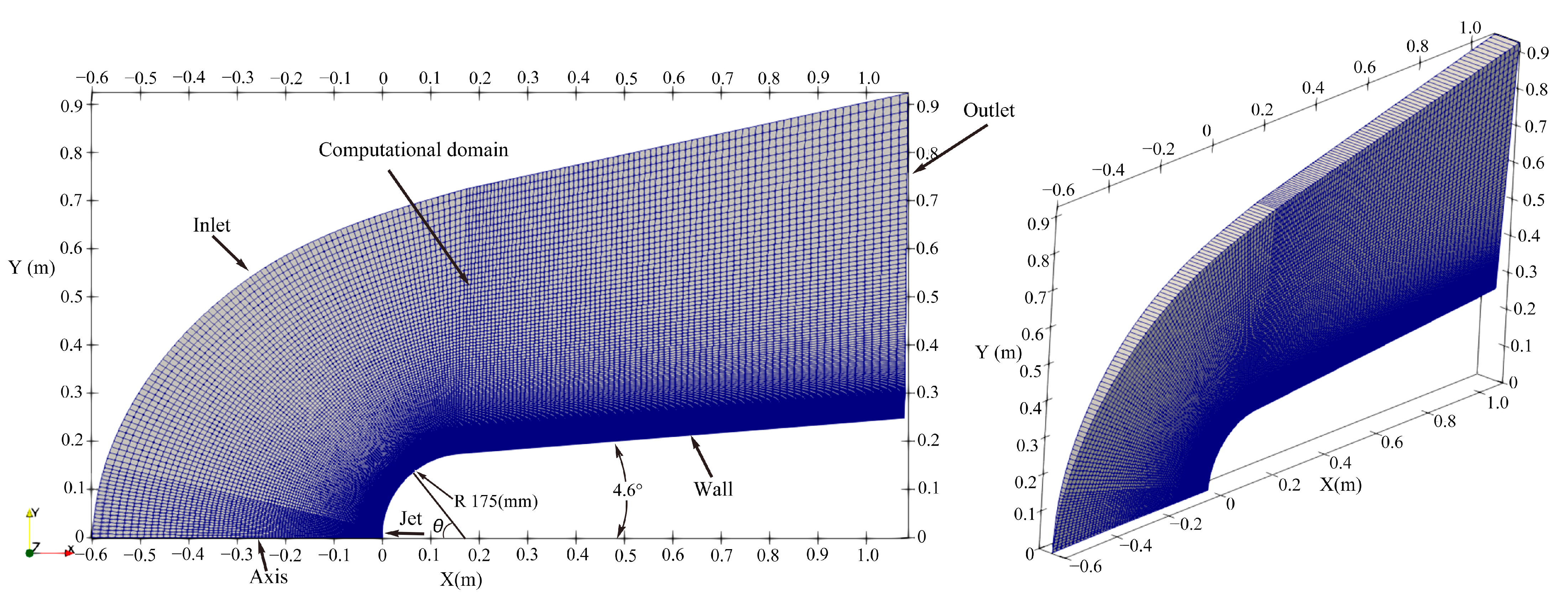
In the current work, we investigated the application of the opposing jet on the ELECTRE vehicle [
22], highlighting the actual operating conditions of the opposing jet. The numerical method of the time-accurate nonequilibrium N-S equations considering vibrational energy excitation and chemical reactions was adopted. The jet characteristics including jet mode, jet state, as well as corresponding jet physics in hypersonic nonequilibrium flows are discussed in detail. Combined with the jet characteristics, we investigated the performance of heat and drag reductions of the opposing jet at various flow rates.
2. Numerical Approach
The opposing jet is installed at the nose of ELECTRE vehicle, which flies at 53.3 km and 13 Ma. High flight speed leads to high temperatures, which result in vibrational energy excitation and a series of chemical reactions, such as O
2 and N
2 dissociations, NO formation, even ionization, etc. These chemical reactions will absorb part of the flow-field heat; thus, considering chemical reactions is vital for the accurate prediction of aerodynamic heat. Moreover, the rarefied gas environment appears at high altitudes, where the relaxation times of chemical reactions and various internal energies of gas molecules (translational, rotational, vibrational, and electronic energies) are prolonged. Once the relaxation time of chemical reactions or internal energies can be comparable to the flow characteristic time, the flow presents the nonequilibrium phenomenon, where the chemical reactions cannot be fully carried out and/or the temperatures of various internal energies are inconsistent with each other. Although particle methods such as the Direct Simulation Monte Carlo (DSMC) method can accurately describe these nonequilibrium phenomena with the Boltzmann equation, the extreme computational effort prevents their application to large geometries and continuum and near-continuum regimes (≤80 km). In order to improve computational efficiency, researchers have proposed a series of nonequilibrium N-S equations based on the conventional N-S equations, considering the energy transfer between various internal energies and the relaxation process of chemical reactions. The most widely used model is the two-temperature model proposed by Park [
23]. In the two-temperature model, one temperature characterizes the translational and rotational energies, named trans-rotational temperature (
Ttr), and the other temperature denotes the vibrational and electronic energies, named vibro-electronic temperature (
Tve).
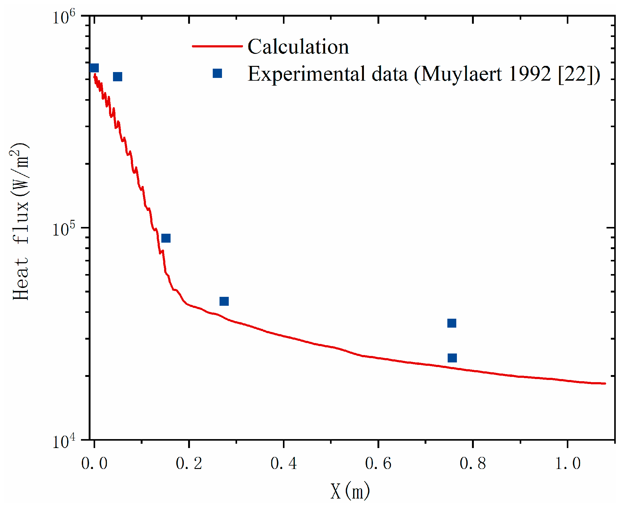
The thermal and chemical nonequilibrium around the ELECTRE vehicle at 13 Ma and 53.3 km were validated in reference [
22]. Thus, the time-accurate thermochemical nonequilibrium N-S equations (two-temperature model) considering thermal and chemical nonequilibrium are applied for the simulation of the ELECTRE vehicle with an opposing jet. According to the freestream conditions, at an altitude of 53.3 km and 13 Ma, the unit Reynolds number (
Re) is 2.13 × 10
4. In Deng’s research [
7], the laminar model was applied in the
Re 6.3 × 10
5; thus, the laminar model can be used in this work. The governing equations of the two-temperature model include the continuity equation for individual species (Equation (1)), momentum equations (Equation (2)), total energy equation (Equation (3)), and vibrational electronic energy equation (Equation (4)). The vibrational energies of different molecules in a mixture are assumed to be tightly coupled with each other; thus, the single vibrational energy equation is applied.
where
is the density of species
s (
),
is the direction vector (m),
t is the time (s),
ui and
uj and are the velocity vectors (m/s),
is the mass diffusion flux (kg/(m
2⋅s)),
is the Kronecker delta (dimensionless),
is the shear stress tensor (Pa),
p is the pressure (Pa),
E is the total energy per unit volume (J/m
3),
is the vibrational energy per unit volume (J/m
3),
and
are the vibrational energy per unit mass of species
s (J/kg),
is the heat conduction vector (J/(m
2⋅s)), and
is the enthalpy per unit mass of species
s (J/kg).
The chemical source term (kg/(m
3⋅s)),
, can be expressed as
where
and
are the forward and backward stoichiometric coefficients (dimensionless) of species
s in the reaction
r, respectively.
Ms is the molecular weight of species
s (
).
kf and
kb represent the forward and backward reaction rate coefficients (
), respectively. The five-species Park 93 chemical kinetic model [
24], including the dissociation reactions of N
2 and O
2 and the exchange reaction of forming NO, is applied for the calculations of
kf and
kb, and written as
where
Ta is the activation temperature (K),
Tc,f is the controlling temperature of the forward reaction defined as
Ttr0.7Tve0.3, and
Keq is the equilibrium constant (dimensionless) calculated by a function of temperature based on the curve-fitted method.
The viscous stress tensor,
, is written as
where
is the viscosity (
) for a mixture, which can be derived from individual species quantities by using corresponding mixing rules. The viscosity of heavy species
s is calculated by the Blottner model [
25], written as
The heat conduction vector,
qj, is assumed to follow the Fourier heat law, and is written as
where
and
are the trans-vibrational and vibro-electronic thermal conductivities (J/(m⋅s⋅K)) of a mixture, respectively, which can be calculated by individual species in accordance with corresponding mixing rules. The trans-vibrational and vibro-electronic thermal conductivities of heavy species
s are calculated by the Eucken model [
26], and written as
where
Cvt,s,
Cvr,s, and
Cvve,s are the translational, rotational, and vibro-electronic heat capacities at a constant volume (J/(kg⋅K)) for heavy species
s, respectively.
The mass diffusion flux for heavy species
s can be calculated by using the modified Fick’s model [
27], as
where
Ds and
Dr are the effective diffusion coefficients of species
s and
r in a mixture (m
2/s). The
Ds is defined as a function of the binary diffusion coefficient (
Ds,r), as follows:
The binary diffusion coefficient for the interactions of heavy species
s and
r,
Ds,r, can be calculated directly by the collision terms, and written as [
27]
where
represents the collision terms (m s) for the heavy species
s and
r, which can be calculated by the related collision integrals.
The average relaxation time between the translational and vibrational energies for molecule
s,
, can be expressed by
where the relaxation time between the translational and vibrational energies for molecule
s and
r,
, is calculated by the Millikan–White–Park model, as [
24]
with
and
where
p is the pressure with the unit of atm. The coefficients
As,r and
Bs,r can be obtained from a table.
ns,r is the number density of the colliding pair for the species
s and
r (m
−3), and
σv,s is the limited collision cross-section (m
2).
The viscosity and thermal conductivities of the mixture are calculated by individual species with Wilke’s mixing rule, which is derived from the Chapman–Enskog method based on kinetic theory and takes into account the collisions between different species in the mixture, written as [
27]
where
Q represents the viscosity (
μ) and thermal conductivity (
κtr,
κve) quantities, and
X is the molar fraction.
ϕs is a scaling factor, defined as
where
Mr and
Ms are the molecular weights of species
r and
s (kg/mol), respectively.
4. Results and Discussions
4.1. High-Temperature Effects
Hypersonic flights are always accompanied by high temperature, which induces a series of chemical reactions and vibrational energy excitation [
32]. When the hypersonic vehicles fly at a high altitude, the relaxation time of chemical reactions and vibrational energy will be greatly prolonged due to the rarefied environment. This will lead to the nonequilibrium effects in which the chemical reactions cannot be fully carried out and/or the vibrational energy of molecules cannot be equilibrium to the translational energy.
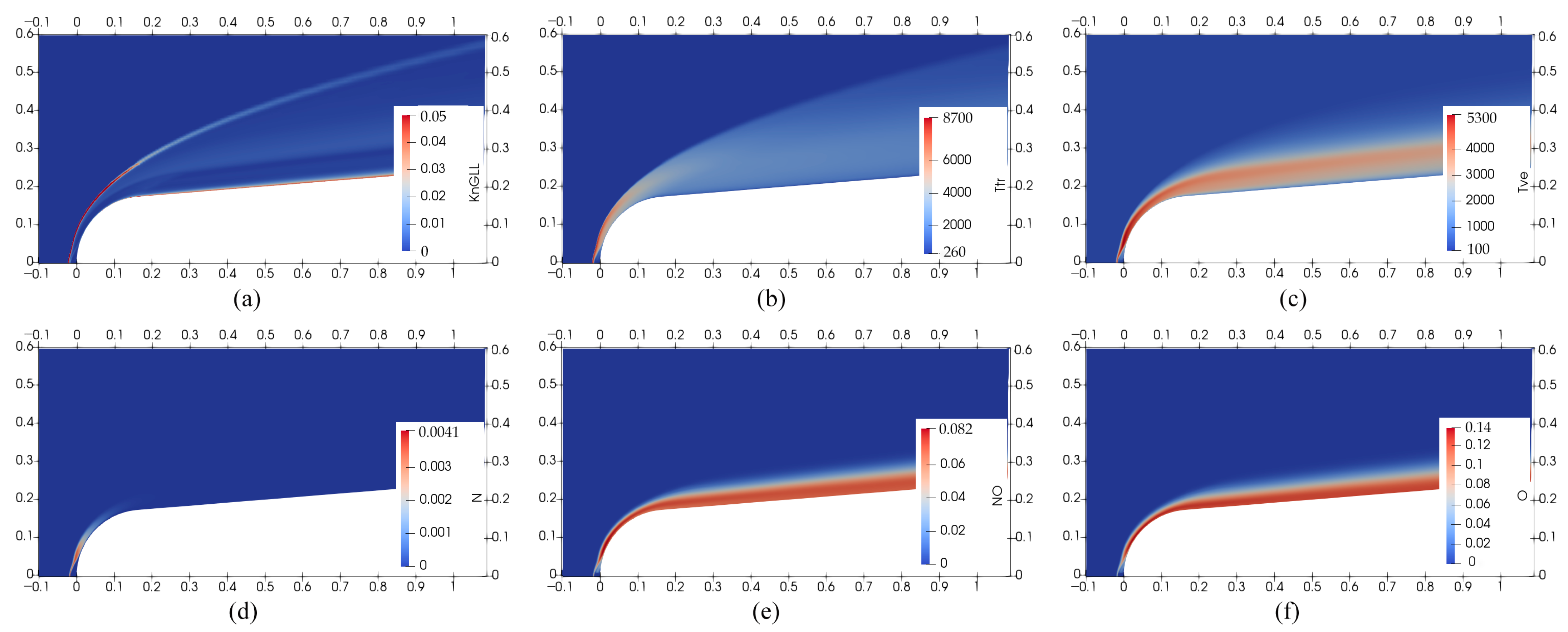
Figure 4 shows the flow features of the ELECTRE vehicle with the R7 jet in case 1 (0.6
mj), including local the Knudsen number (
KnGLL),
Ttr and
Tve, and mass fractions of N, NO, and O. As shown in
Figure 4a, the
KnGLL at the head shock reaches 0.05, indicating that the conventional CFD method is not appropriate [
33], and both the thermal nonequilibrium and chemical nonequilibrium should be considered. The comparison of
Figure 4b,c shows an obvious thermal nonequilibrium, in which the
Ttr is obviously bigger than
Tve at the shock wave. The chemical reactions adopted in this work include N
2 dissociation, O
2 dissociation, and exchange reaction for NO formation. The O
2 dissociation begins at 2500 K and ends at 4000 K, the N
2 dissociation starts at 4000 K and complete dissociation is achieved at 9000 K, and the NO exchange reaction occurs at 2500–9000 K [
34]. As shown in
Figure 4d–f, most O
2 near the wall is changed into NO and O through dissociation and exchange reactions. A small amount of N is generated at the shock wave ahead of the ELECTRE vehicle; this is because N
2 dissociation requires a higher temperature. It can be seen that the high-temperature effects must be considered in the practical application of the opposing jet in hypersonic vehicles.
4.2. Jet Transient Characteristics
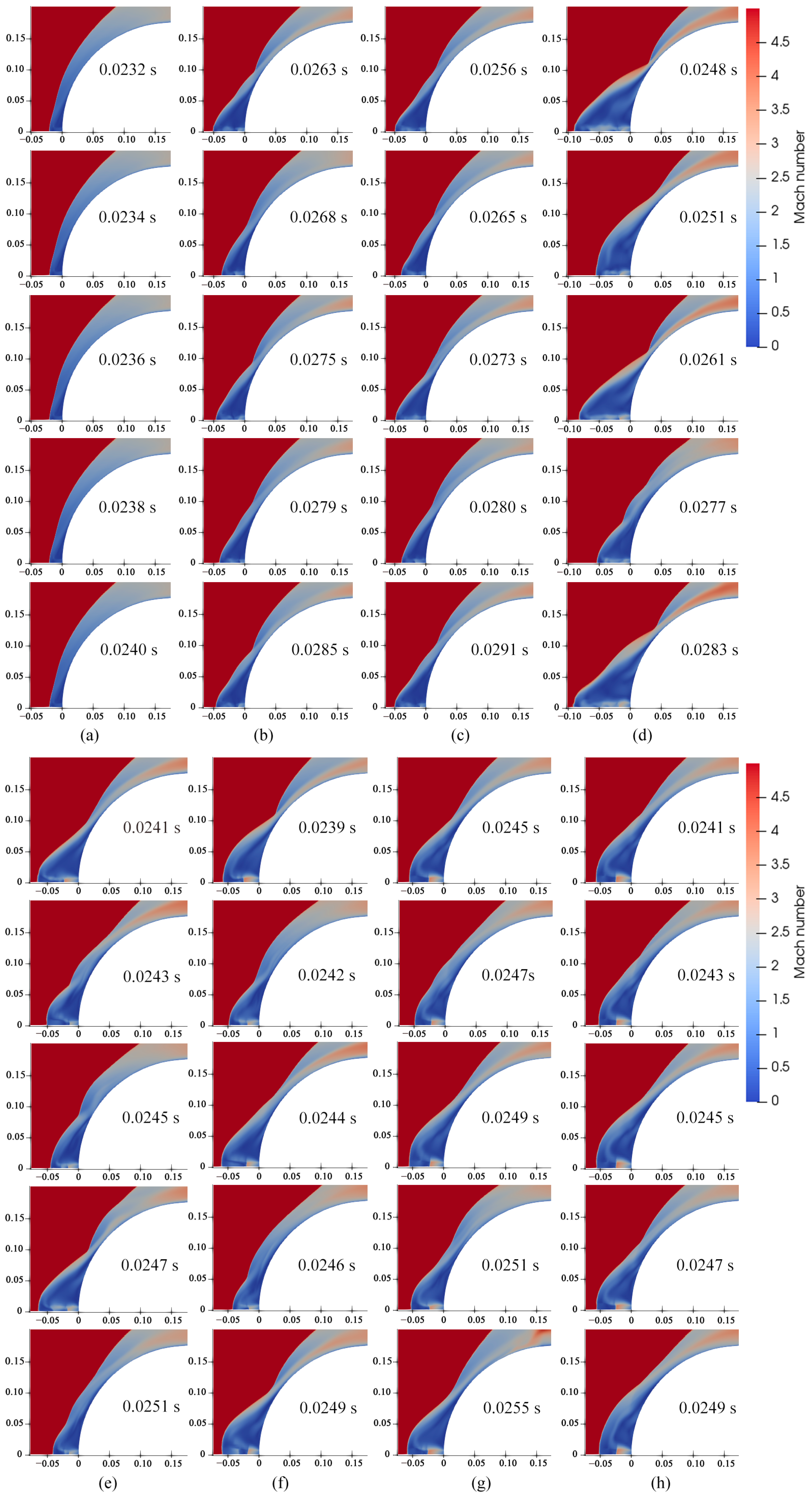
Figure 5 shows the Mach numbers of the R7 jet in cases 1–8 at different times. The shock wave distance (SSD) and the shape of the bow shock wave of the jet in case 1 have no variation at different times, indicating that the R7 jet is in a steady state under the 0.6
mj jet flow rate. In other cases, the SSD and the shape of the bow shock wave show a certain degree of change at different times, implying that the R7 jet will be unstable when the jet flow rate is greater than a critical value. Apparently, the oscillation amplitude of the SSD is the largest in case 4, which indicates that the instability of the jet is the strongest at the 2
mj flow rate.
As the jet flow rate increases, there are three jet modes in cases 1–8. At a low flow rate (case 1), the jet overflows from the jet inlet, pushes the shock wave away from the wall for a short distance, and hardly affects the shock shape. This jet mode is named the overflow mode in this work. With the increase in the jet flow rate (cases 2–4), the jet behaves as a long penetration mode (LPM), in which the jet needs to pass through multiple jet cells to be consistent with the ambient pressure. After case 4, the jet mode starts to transfer from LPM to the short penetration mode (SPM) with the increasing jet flow rate. Cases 5 and 6 show the above-mentioned transition, a notable feature of which is that there are single-cell and multi-cell jets in the jet motion. With a further increase in jet flow rate (cases 7 and 8), the jet presents the SPM accompanied by a Prandtl–Meyer expansion and obvious Mach disk.
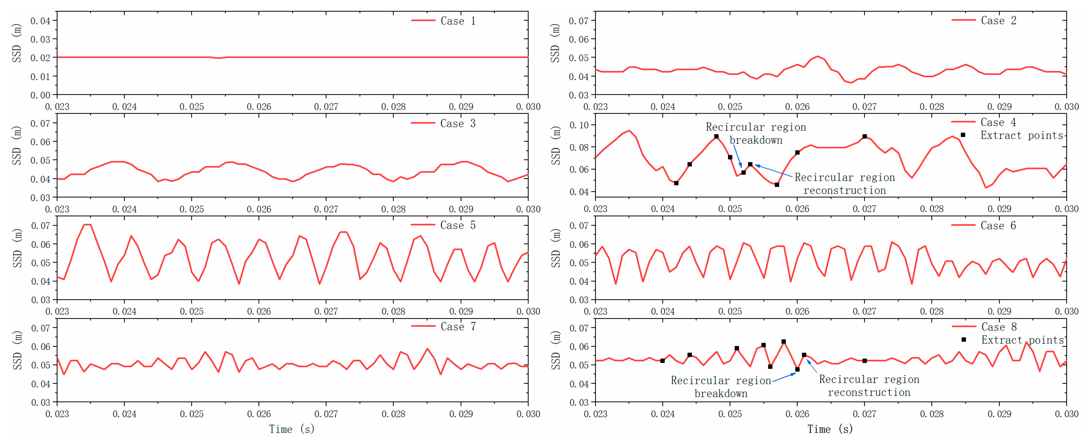
Figure 6 shows the SSD of R7 jet in cases 1–8 from 0.023 s to 0.03 s. As presented in cases 3–8, the SSD oscillation amplitude first increases and then decreases with the increasing jet flow rate, indicating that there is a jet with the strongest instability at a certain jet flow rate. As the jet is transferred from LPM to SPM (cases 4–7), the SSD oscillation amplitude decreases but the SSD oscillation frequency increases with the increasing jet flow rate. This conclusion is consistent with the results in references [
7,
21]. The SSD oscillation amplitude in cases 7 and 8 with SPM is much smaller than that in case 4 with LPM, indicating that the jet in SPM is more stable than that in LPM. Therefore, the jet state in SPM is also defined as nearly steady state in reference [
35].
Previous studies usually used PR as a dependent variable to characterize the jet mode. However, this parameter is not rigorous. As shown in
Table 1, the PR of case 1 is larger than that of case 3, while the jet flow rate of case 1 is lower than that of case 3. Apparently, the description that jet mode varies from overflow mode to LPM with decreasing PR is wrong. Therefore, the jet flow rate is the fundamental factor affecting the jet mode, which is consistent with Kim’s research [
12]. However, the SSD oscillation frequencies of case 2 and case 3 are different, indicating that PR affects the jet characteristics to a certain extent at a constant jet flow rate.
Finally, it can be concluded that the jet mode varies from the overflow mode to the LPM and finally to the SPM with the increasing jet flow rate. The jet presents a steady state in the overflow mode, and an unsteady state in the LPM and SPM.
Cases 4 and 8 of the R7 jet are selected to explore the transient characteristic of LPM and SPM, respectively, and several typical times are extracted (seen in
Figure 6) to analyze the unsteady mechanism of LPM and SPM. According to experiments of opposing jets at lower pressures, Shang [
36] found a self-sustained oscillatory motion existing in LPM, and it was explained that the motion was maintained by a feedback loop between the shear layer and the Mach disk. Chen [
37] investigated the LPM using large-eddy simulation and clarified the feedback mechanism whereby the self-sustained oscillatory motion is sustained by the upstream-propagating disturbance to the Mach disk through the recirculation subsonic region and downstream propagation in the conical shear layer.
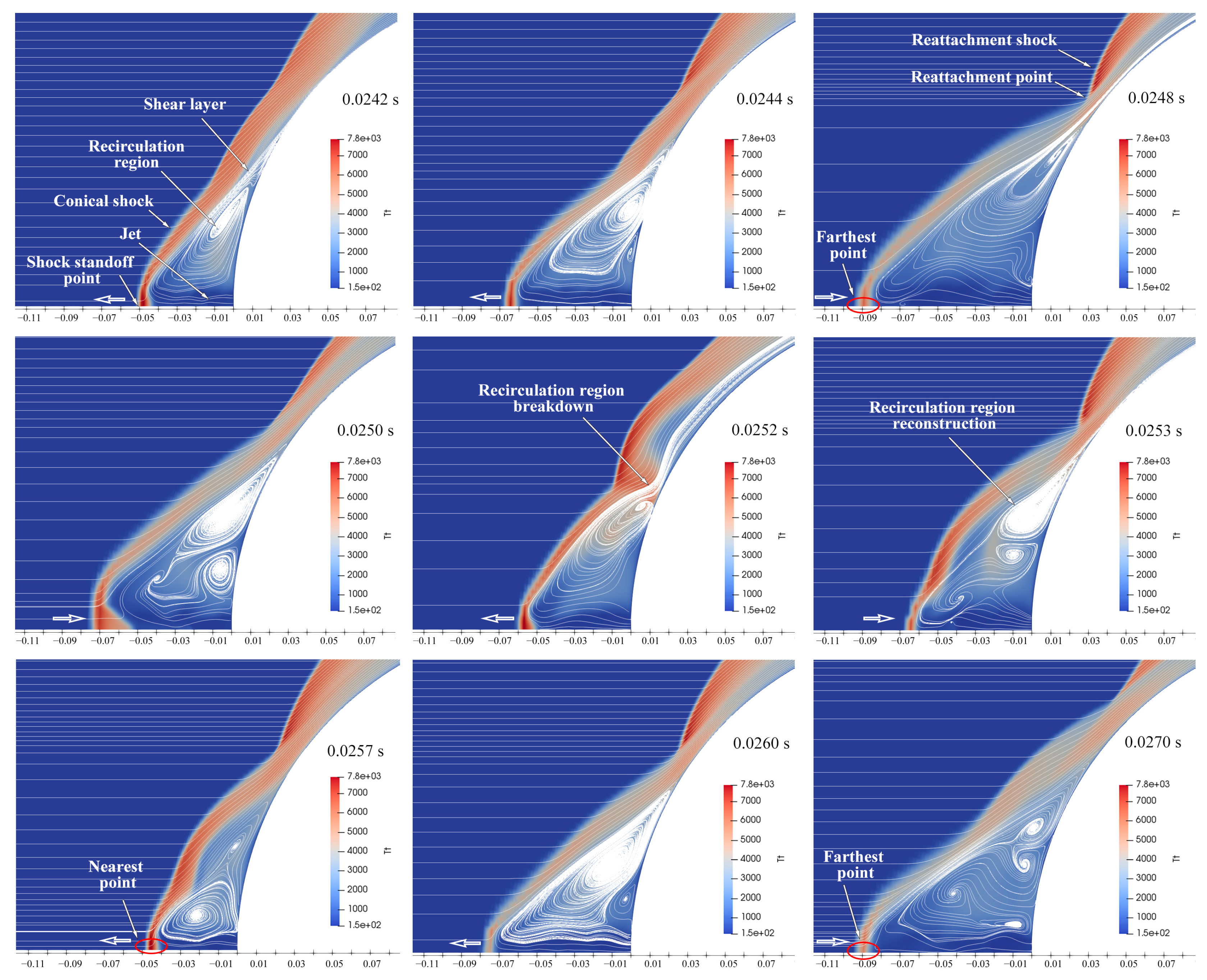
Figure 7 shows the variations in streamline and temperature of the opposing jet in LPM within 0.0242–0.0270 s. As shown, the shock standoff point oscillates periodically along the axis, which agrees with Shang’s experiments [
36]. As discussed by Shang [
36] and Chen [
37], the LPM transient characteristics depend on various interactions, including the shear layer/shock, the shear layer/jet boundary, and the shock/jet. These interactions are coupled with each other, which aggravates the complexity of the LPM mechanism. However, we propose a simple explanation to analyze the LPM transient characteristics, based on the relation between the recirculation region size and its pressure.
The shock standoff point moves gradually away from the wall starting at 0.0242 s until it reaches the farthest position at 0.0248 s. At the same time, the reattachment point gradually approaches the wall, and the recirculation region becomes larger and induces a decreasing pressure. The recirculation region cannot support the shock owing to lower pressure; thus, the shock standoff point starts to move towards the wall after 0.0248 s, accompanied by the shrinking of the recirculation region and the increasing pressure in the recirculation region. When the pressure in the recirculation region increases more than that of the reattachment point, the recirculation region collapses at 0.0252 s, i.e., the jet in the recirculation region flows directly downstream. At 0.0253 s, the reattachment point is attached to the surface again to quickly reconstruct the recirculation region. In the recirculation region reconstruction process (0.0252–0.0253 s), the shock standoff point moves away from the wall. Subsequently, the shock standoff point begins to move towards the wall until arriving to the nearest point at 0.0257 s. After 0.0257 s, the shock standoff point begins to move away from the wall again, and the jet movement starts to enter the next cycle that is similar to the movement at 0.0242–0.0257 s.
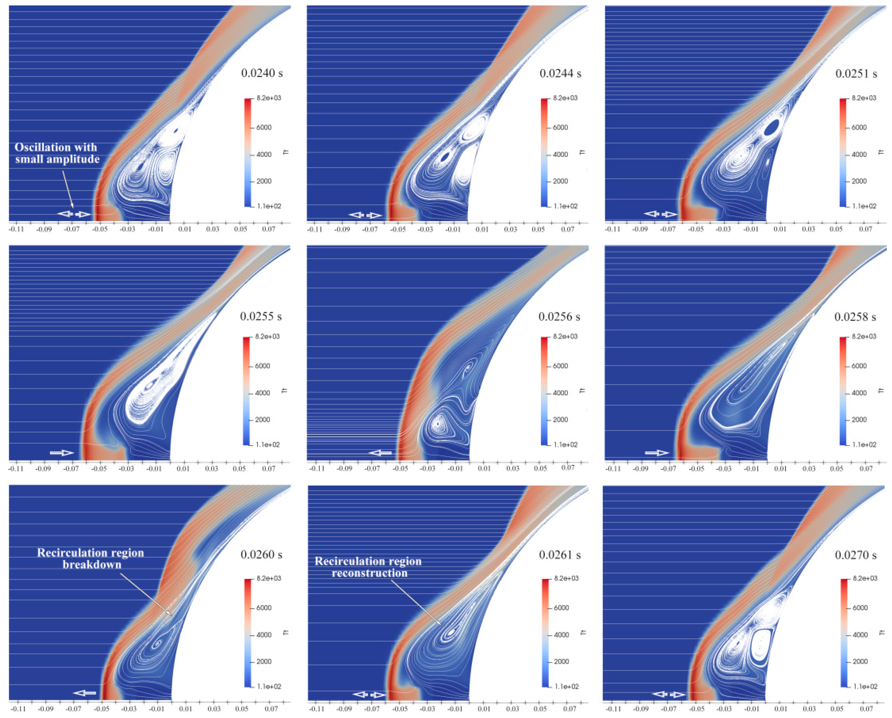
Figure 8 shows the transient characteristic of the opposing jet in SPM within 0.0240–0.0264 s. Combined with
Figure 6 (case 8), it can be seen that the shock standoff point oscillates with small amplitude in nearly half of an oscillation cycle. At this stage, the jet is in a relatively stable state and the shock shape is consistent with that in 0.0240 s. After 0.0240 s, the oscillation amplitude gradually increases, accompanied by an apparent change in the shock shape. Until 0.0260 s, the recirculation region collapse occurs, accompanied by the reattachment point being pushed away from the wall. Similar to LPM, the recirculation region is quickly reconstructed after its collapse, as shown in 0.0261 s. After the reconstruction of the recirculation region, the jet returns to a relatively stable state. All in all, we can easily conclude that the main reason for the jet instability in SPM is the recirculation region collapse.
4.3. Jet Modes
As investigated above, there are three jet modes with the jet flow rate increasing: overflow mode, LPM, and SPM.
Figure 9a–c shows the interactions between the freestream and these three jet mode. As shown in
Figure 9a, the jet in overflow mode pushes the stagnation point a short distance away from the wall, forming a recirculation region, inducing the separation of a boundary layer. The shear layer locates around the recirculation region, which represents the shear action of the jet and the freestream near the recirculation region. In the interaction between the freestream and the jet in LPM (
Figure 9b), the jet pushes the stagnation point of the freestream shock far away from the wall. At the same time, the shape of the freestream shock also changes significantly from the bow shock to the conical shock. Daso’s experiments revealed that the visibility of freestream shock structure was weak [
5]; thus, the shock is also called the wake bow shock in investigations [
6,
38]. In addition, a reattachment shock is formed in the shoulder of the blunt body, in which the aerodynamic heat attains peak value. In the interaction between the freestream and the jet in SPM (
Figure 9c), the jet presents as a Prandtl–Meyer expansion and terminates with an obvious Mach disk. The shape of the freestream shock changes back to the bow shock. There is also a reattachment shock in the jet in SPM, while the position of reattachment shock deviates obviously from the wall compared with that in LPM.
Numerous studies have shown that the jet must eventually be consistent with the ambient pressure after a series of expansion/compression, which means that the total pressure of the jet on the axis must be reduced to the pressure after the shock wave [
3,
20].
Figure 10a–c shows the jet structures of overflow mode, LPM, and SPM, and the corresponding values of Mach number and pressure on the axis. For overflow mode (
Figure 10a), the most obvious feature is that the Mach number of the jet is less than one in the whole jet, and the Mach number decreases gradually along the jet direction. At the stagnation point, the pressure reaches the peak value, and the Mach number reaches the minimum value. For LPM (
Figure 10b), the jet undergoes a series of expansion and compression caused by the boundary reflection until the jet pressure equals the pressure of the stagnation point. There are multiple jet cells, in which the jet velocity along the axis first increases and then decreases, while the change trend of pressure is opposite that of velocity. Certainly, the jet expansion is accompanied by the velocity increasing and the pressure decreasing, and the jet compression is followed by the velocity decreasing and the pressure increasing. Referring to the changes in Mach number and pressure along the axis, the expansion and compression shocks are drawn in
Figure 10b. Multiple shock structures exist in the LPM, but the intensity of the shock decreases with the jet going forward. For SPM (
Figure 10c), the jet expands around the lip of the nozzle outlet through expansion fans, and reflects off the jet boundary as compression waves, which coalesce into a barrel shock structure. When this barrel shock encounters the Mach disk, an oblique reflected shock forms, as shown in
Figure 10c. The value of the Mach number along the axis shows that the jet is accelerated before reaching the Mach disk, and decelerates sharply after the Mach disk until reaching the stagnation point. According to the peak value of pressure, the stagnation points of three jet modes are also denoted in
Figure 10a–c. It can be seen that although the SSD of the jet in SPM is smaller than that in LPM, the distance between the stagnation point and the freestream shock of the jet in SPM is larger than that in LPM.
4.4. Jet Radius Effects
The discussions in
Section 4.2 and
Section 4.3 on the jet characteristics are based on the R7 jet. To explore the influence of the jet radius on the jet characteristics, two other jets are provided: R14 and R21. The jet modes of the R7, R14, and R21 jets with the same flow rate and the same PR are investigated, as shown in
Figure 11 and
Figure 12, respectively.
In the investigation of jet modes of the three jets with flow rates from
mj to 6
mj, the jet pressures of R14 and R21 jets in these flow rates are set as 13,922 Pa to ensure that the jet outlet pressure is bigger than the pressure aftershock, so the jet can be ejected into the flow-field. The corresponding jet velocity is calculated by the given jet flow rate and pressure. At the same flow rate, the jet velocities of R7 jet, R14 jet, and R21 jet decrease, resulting in the decreasing jet total pressure. Due to different jet total pressures, the jet modes of the three jets in the same flow rate are different. As shown in
Figure 10, the R14 jet at the
mj–2
mj flow rates and the R21 jet at the
mj–6
mj flow rates are in overflow mode, while the R7 jet at the
mj–2
mj flow rates is in LPM. At the 6
mj flow rate, the jet mode of R7 is SPM, that of R14 is LPM, and that of R21 is overflow mode.
As shown in
Figure 12, the jet radius affects the jet mode to some extent. At the PR 1.27, the R7 jet is in LPM, while the R14 jet and the R21 jet are in overflow mode. At the PR 2.53, the R7 jet presents the characteristics of LPM, while the R21 jet has the characteristics of overflow mode. This indicates that the jet mode of the opposing jet not only depends on the PR, but also relies on the jet radius. Additionally, no LPM appears in the R21 jet in the PR range of 1.27 to 7.60, indicating that with an opposing jet with a large jet radius, the jet mode will directly transition from overflow mode to SPM with the increasing jet pressure/flow rate. This is attributed to the interaction between the jet and the shock. The small contact area between the shock and the small radius jet leads to a large contact stress; thus, the jet with small radius has stronger penetration ability. When the jet radius is larger than a critical value, the LPM representing the strong penetration ability disappears.
4.5. Heat and Drag Reductions
The heat reduction is defined as the aerodynamic heat ratio of the ELECTRE with a jet to that of the ELECTRE without a jet. Similarly, the drag reduction is the ratio of the drag of the ELECTRE with a jet to that of the ELECTRE without a jet.
Figure 13 shows the heat and drag reductions of R7, R14, and R21 jets at flow rates of
mj, 2
mj, 4
mj, and 6
mj. As shown in
Figure 13a, the R7 jet at
mj (case 3) and 2
mj (case 4) not only can provide effective thermal protection, but also further increases the aerothermal load on the ELECTRE vehicle. As found in
Section 4.3, the jet modes of R7 jet at
mj and 2
mj are LPM, indicating that the jet in LPM will worsen the aerodynamic heat environment around the hypersonic vehicles, which is consistent with the conclusions of Hayashi’s [
4] and Daso’s [
5] experiments. At 4
mj (case 6) and 6
mj (case 8), the R7 jet effectively reduces the aerodynamic heat, implying that the jet in SPM can provide thermal protection.
In 0.2–0.22 s, the heat reductions of the R14 and R21 jets have an apparent decrease. This is because the chemical reactions are added in 0.2 s, which adsorbs a part of the aerodynamic heat in the flow-field. The related calculation converges to 0.22 s; thus, the related discussions of the jet are based on the results after 0.22 s. The heat reductions of the R14 jet at mj–2 mj and the R21 jet at mj–6 mj almost have no oscillation in 0.22–0.30 s. This is because the jet modes of these jets are in the overflow mode, which corresponds to the steady state. Compared with the R7 and R14 jets, the R21 jet at the four flow rates provides better thermal protection, and the thermal protection effect is improved with the increasing jet flow rate. Therefore, it can be concluded that in the overflow mode, the opposing jet with a large radius has a better thermal protection effect, and the thermal protection effect can be enhanced with the increasing jet flow rate.
As shown in
Figure 13b, the R7 jet at the
mj–6
mj jet flow rates can provide effective drag reduction, which indicates that the opposing jet in both LPM and SPM can provide drag reduction. However, the drag reduction effects of R14 at the
mj–2
mj flow rates and R21 at the
mj–6
mj flow rates are inapparent, indicating that the jet in overflow mode cannot provide effective drag reduction. Compared with the R14 and R21 jets, the R7 jet can effectively reduce the drag in the
mj–6
mj flow rates, which indicates that a small jet radius contributes to the drag reduction.
Figure 14 shows the heat and drag reductions of R7, R14, and R21 jets at PR of 1.27, 2.53, 5.07, and 7.60. For the three jets, the boundary conditions (Mach number, static pressure, and static temperature) of PR1.27, PR2.53, PR5.07, and PR7.60 correspond to case 3, case 4, case 6, and case 8, respectively, as shown in
Table 1. As shown in
Figure 14a, in the four PRs, the thermal protection effects are enhanced with the increasing jet radius. At the same PR, the jet flow rate increases with the increasing jet radius. Thus, the fundamental reason for the improvement of the heat reduction effect is the jet flow rate increasing. As shown in
Figure 14b, in the same PR, although the drag reduction ability of the jet is enhanced with the increasing jet radius, the enhancement effect is not obvious. Especially in the PR1.27, the
Q/
Qno jet of R14 and R21 jets are only slightly lower than that of the R7 jet.
For the R21 jet, both the thermal protection and the drag reduction are enhanced with the PR increasing. As discussed in the above section, there is no LPM in the R21 jet at mj–6 mj flow rates. Therefore, the effect of heat and drag reductions of an opposing jet with a larger jet radius and no LPM occurring can be enhanced by increasing the PR/jet flow rate.
5. Conclusions
We investigated the ELECTRE vehicle with an opposing jet at an altitude of 53.3 km and 13 Ma by a numerical method adopting time-accurate, nonequilibrium N-S equations. The high-temperature effects existing in hypersonic flows, which include chemical reactions and vibrational energy excitation, were considered. This paper focused on the exploration of the jet characteristics, including jet state and mode, as well as its performances in heat and drag reductions in hypersonic nonequilibrium flow.
Three opposing jets with radii of 7 mm, 14 mm, and 21 mm (R7 jet, R14 jet, and R21 jet) were investigated. When the jet radius of the opposing jet is small (R7 jet), the jet mode varies from the overflow mode to the LPM and finally to the SPM with the increasing jet flow rate. However, with a large radius (R21 jet), the jet mode directly changes from the overflow mode to the SPM with the increasing jet flow rate. The jet in overflow mode presents a steady state, while the jets in LPM and SPM behave in an unsteady state.
For the overflow mode, the jet Mach number is less than one and the jet pressure is slightly bigger than the pressure after shock. The jet in overflow mode has little effect on the shock shape. For the LPM, the jet needs to experience multiple jet cells accompanied by a series of expansion and compression until the jet pressure is equal to the stagnation point pressure. For the SPM, a jet cell is generated by the Prandtl–Meyer expansion and terminated by an obvious Mach disk.
The jet in overflow mode and SPM can provide effective thermal protection, and the thermal protection effect can be enhanced by improving the jet flow rate. However, the jet in LPM worsens the aerodynamic heat environment around the ELECTRE vehicle. The jets in LPM and SPM can effectively reduce the aerodynamic drag, while the jet in overflow mode cannot provide effective drag reduction. The comparisons of the heat reductions of the R7, R14, and R21 jets at the mj–6 mj flow rates show that the R21 jet can provide better thermal protection in all jet flow rates and reduce the aerodynamic heat to 20% in the 6 mj flow rate. This indicates that the jet with a large radius and in the overflow mode can have a better thermal protection effect. Compared with R14 and R21 jets, the R7 jet can effectively reduce more aerodynamic drag, indicating that a small jet radius contributes to drag reduction.


