1. Introduction
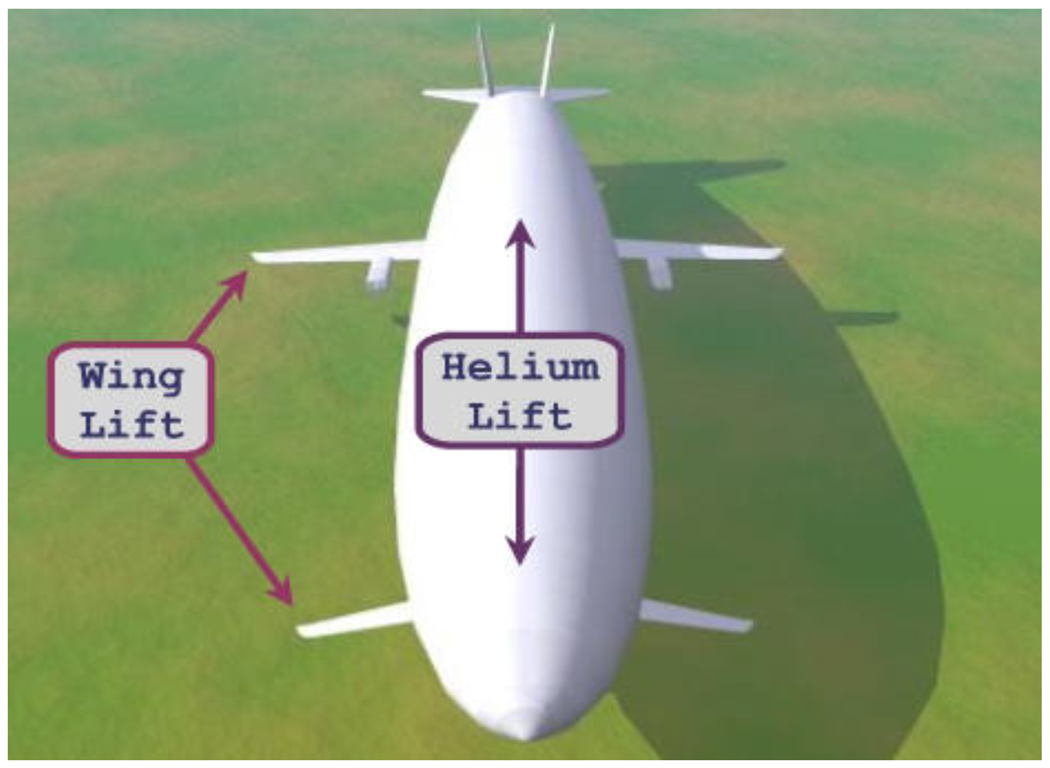
Airships are a type of aerostat, or lighter than air (LTA) aircraft, that can remain aloft in the air by virtue of buoyant or aerostatic lift. These aircraft have been around for the past several decades. Since the culmination of World War II, airships have been developed for a multitude of applications, both civil and military in nature. Hybrid buoyant (HB) airships are a type of powered, LTA aircraft, also known as
Dynastats and refer to the category of airship shown in
Figure 1 which generate lift as a combination of two sources, namely aerostatic (buoyant) lift and aerodynamic lift. The aerostatic lift is a result of the low-density lifting gas stored inside the hull of the airship, and the additional aerodynamic lift is produced by the attachment of wings to the conventional airship hull.
Stratospheric airships usually operate at altitudes of 15–25 km above sea level [
1,
2]. At these altitudes, the atmospheric conditions are relatively less intense and the wind directional changes are more stable [
3]. These airships vary significantly as compared to conventional aircraft in terms of general configuration, aerodynamic configurations, lift generation principles etc [
4]. HB airships have several advantages when compared to conventional airships [
5]. These airships have a much shorter ground roll, as compared to general aircraft. They also have significantly better ground handling capabilities as compared to conventional airships. HB airships can carry much heavier payload than similar sized conventional airships [
5]. They are also more aerodynamically efficient than conventional airships [
5,
6]. The capability of the HB airships to combine aerodynamic lift with buoyant lift allows it to sustain normal flight for significantly longer durations than conventional airships [
7]. In recent years, there has been increasing interest in development of these airships owing to their long endurance flight capabilities at high altitudes [
8]. The high endurance capabilities of the HB airships make it favourable for military applications such as high-altitude surveillance missions [
9], as well as for several commercial and strategic applications such as wireless broadband telecommunications [
10], digital broadcasting [
11], coastal surveillance [
12], remote sensing and GPS augmented navigation systems [
13].
However, in order to achieve the long endurance capabilities, it is not feasible to carry large volumes of fuel due to sizing and weight related constraints on the design. This issue can be overcome by utilizing solar energy to generate the power required by the airship to overcome drag-related losses and for other on-board functions. Solar energy is a renewable source of energy and can be exploited thoroughly, especially at the high altitudes where the airships are being designed to operate [
14]. As a result of the development in renewable sources of energy, solar energy is proving to be a highly efficient and durable source of clean energy for HB airships [
15]. A significant drawback of this mode of energy is the lack of solar power available during the night. This can be easily overcome though, by employing energy storage systems in the form of fuel cells which have a much greater specific energy density value (1000 Wh/kg) as compared to traditional lithium batteries (200∼300 Wh/kg) [
15]. This highlights the enormous potential of solar powered systems, especially in terms of weight reduction and energy storage capabilities.
In recent years, a significant amount of research work has been carried out focusing on the conceptual design of winged airships [
16,
17,
18]. Haque and their associates have major contributions on winged-hull dynastats. Majority of these studies have focused on the evaluation of the aerodynamic characteristics of winged-hull dynastats using numerical simulations, viz., computational fluid dynamics (CFD) solvers [
19,
20,
21,
22,
23] and experimental investigations using wind tunnels [
19,
24]. Very few attempts (e.g., [
25,
26]) have been made focusing on the conceptual design of winged airships. There are other studies that have focused on design optimization [
18], flight performance analysis [
27,
28], stability analysis [
29,
30], and fabrication methods to develop models for wind tunnel testings [
17] of winged hybrid airships. To the author’s knowledge, however, there is no study available in open literature focusing on the multidisciplinary design optimization of a winged hybrid airship.
Interest in unconventional configuration hybrid airships for various applications has piqued significantly. In the past, most studies developed conceptual designs for conventional airships with axisymmetric bodies of revolution. However, more recently, successful unconventional designs have been proposed. A few such configurations are the delta winged lifting-body [
31], multi-lobed tandem wing [
32,
33,
34,
35], tri-lobed hull [
15,
36] etc.
There are only a few examples of proposed winged-hull dynastats as the concept is gaining momentum only recently. One prominent winged dynastat concept is that of the Dynalifter, shown in
Figure 2, which was proposed and developed by Ohio Airships. The fuselage of the dynalifter was filled with cells containing a lifting gas (Helium). These cells can expand or contract as required, within the frame of the fuselage. Helium provides 30 to 80 percent of the lift, depending upon the circumstances, while internal combustion provides the forward motion. In another study by Liu et al. [
37], a hybrid airship called the Aeroship, has been developed. The study involved the integration of an airship module with a wing (propulsion) module to develop a HB airship capable of meeting certain mission requirements. Mackrodt [
31] calculated the aerodynamic analysis of a hybrid Zeppelin to obtain the optimum configuration for a winged Zeppelin airship, as shown in
Figure 3. This concept essentially consists of a slender delta wing incorporated into a rigid airship structure. Another possible design for a winged hull airship is the proposed Ames Megalifter [
38]. The design resembles that of a classic airplane with fixed wings attached to the hull of the airship.
WB-1010, shown in
Figure 4 and
Airship One, shown in
Figure 5 are two examples of modern winged-hull dynastats [
40].
There are few studies in open literature that have been focused on the design and analysis of the inflatable flying wing concept for various applications. Inflatable flying wing concepts are touted to be a viable alternative to the conventional aircraft. Feng and Ye [
43] demonstrated the aerodynamic performance of buoyancy lifting row flying-wings using numerical simulations. The study shows that the row straight flying-wings and row sweptback flying-wings increases the aerodynamic efficiency (lift over drag ratio) by 40% and 20%, respectively. Baraniello and Persechino [
44] proposed a conceptual design methodology for hybrid platforms including an inflatable flying wing, a conventional airship and two multi-lobed configurations for Earth observation and telecommunications. The key conclusion of the study is that hybrid airships are better configurations for high altitude applications in terms of power consumption, size, weight, and safety. Buckley et al. [
45] proposed a design methodology based on aerodynamic shape optimization for inflatable flying wing powered by solar energy for low altitude applications. The authors formulated the shape optimization problem to minimize the size of the airship corresponding to the size of the hangar by optimizing the span and envelope root chord. In this study, a widely used aerodynamic shape optimization methodology used in several studies on unconventional aircraft, viz., jet stream was utilized. The key outcome from the results indicate that such a configuration could be well suited for operations in remote areas.
This study presents the conceptual design of a solar powered winged-hull airship using the MDO approach, wherein the fourteen design variables obtained by coupling of the five modules of the airship (geometry, aerodynamics, energy, environment, structure), are optimized using the particle swarm optimization approach, for a given set of user-defined operating conditions.
2. Motivation
In recent years, interest in winged-hull airships has increased significantly. This is a result of the several advantages of such configurations over conventional airships, such as long endurance capabilities, improved aerodynamic and stability characteristics, improved resistance to wind and atmospheric fluctuations, among others. The combination of aerostatic buoyant lift with aerodynamic lift, along with the application of clean regenerative sources of energy to provide stable source of power leads to the numerous advantages mentioned above, of such configurations. This has led to the development of several winged-hull configurations based on data accumulated from wind tunnel testing, and numerical simulation analysis.
A hybrid airship has the potential to be much more fuel efficient and aerodynamically efficient, thereby making it a favourable candidate for a greener and economically efficient mode of transportation. In today’s world, where phenomena such as global warming and climate change are on the rise as a result of several decades of toxic fuel emissions caused by human activities, the need for greener, environmentally conscious designs of vehicles which rely on clean, renewable sources of energy, is of the utmost importance. Therefore, an optimization study which couples all the modules of the winged hull airship along with the concerned environmental and solar modules, in order to generate a good estimate of an initial design of such an airship, carries great benefits.
3. Description of Modules Used in the Study
In this study, the MDO framework involves five modules. The first one, viz., environment module, involves the parameters related to the specific operating location, e.g., temperature, pressure and density of ambient air, and wind speed. The next module, viz., geometry, describes the airship envelope profile generator, geometry and layout of the solar arrays, and the planform geometry of the wing. The third module, viz., aerodynamics, handles the interaction between the above two modules. The fourth module, viz., energy, describes the procedure to estimate the total energy supplied and total energy required. The last module, viz., structures, describes the mass breakdown models of the HB airship. The subsection that follows describes the key formulae and procedures utilized in this study pertaining to these modules.
An extended design structure matrix (XDSM) [
46] depicting the inter-dependency of the various modules is shown in
Figure 6.
As seen in
Figure 6, each of the modules requires and provides information to each other for the different stages of the MDO process. Flow of information is almost entirely sequential in nature. Coupling of the modules to the optimizer is carried out at the end of the process, after the processing of the penalty function, so as to ensure that the optimizer progresses towards the better regions of the design space.
3.1. Geometry Module
The geometry module constitutes the set of functions developed and utilized to generate the envelope and wing geometries of the airship, as well as the integration of the envelope surface with the wing planform.
3.1.1. Envelope Design
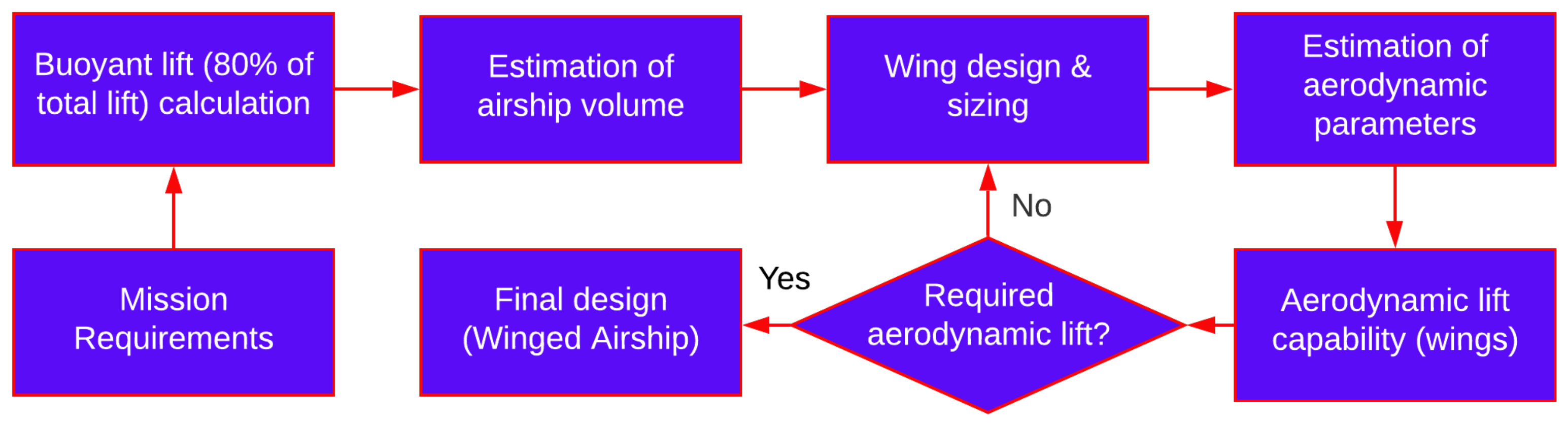
The steps involved in the sizing of envelope and wings of the HB airship are shown in
Figure 7.
For design of the airship envelope, a shape generation algorithm viz.,
Gertler-58 Shape Generator, is utilized. This shape generator has proven to be capable of capturing specific shapes of envelopes used in previous designs successfully [
47].
The general shape of the envelope in a 2D plane is given by the six-degree polynomial,
where,
,
,
,
,
and
are the coefficients of the polynomial which are essentially determined by five primary design variables (geometric parameters). These are - maximum diameter location of the envelope (
m), nose radius of the envelope (
), tail radius of the envelope (
), prismatic coefficient (
), and length over diameter (Fineness) ratio (
). The design variables are described in
Figure 8.
Now, the constraints applicable for an airship are applied, following which a set of six linear equations are obtained, which contain six unknowns [
47]. These equations can be expressed in matrix form as follows:
The above equations need to be solved for the six unknowns
,
,
,
,
, and
. The final equation becomes:
To obtain the final envelope surface, the curve generated from Equation (
3) is revolved about the desired axis to produce the axisymmetric shape of the airship. For the present study, the NPL low drag shape has been selected for the airship envelope profile. This shape has been developed by the National Physics Laboratory (NPL) [
38]. It essentially consists of two half prolate spheroids (or ellipsoids), as shown in
Figure 9.
The shape equation for the profile is defined as:
where the two design variables are the major and minor radius of the ellipse, i.e.,
a and
b, respectively.
In terms of the
Gertler-58 shape generator, the values of the five design variables required to accurately estimate the NPL low drag profile are given in
Table 1.
For the purposes of the present study, MATLAB® was used to implement the Gertlter-58 shape generator algorithm to obtain the desired airship envelope shape.
3.1.2. Wing Design
For the present study, the wing geometry is developed using the methodology based on Bézier surfaces as defined by Sóbester and Forrester [
48]. The methodology established for the design of the wing relies on the definition of a spanwise (
) vector. This vector describes the spanwise stations along which the airfoil sections are to be generated. This station vector is essentially an additional dimension, whose curvilinear axis is fixed to the wing leading edge (LE). The scale of this curvilinear axis is normalized. This implies that
describes the wing root section and
describes the wing tip section. Now, the spanwise variations of the various wing parameters such as chord, camber, sweep, dihedral, twist etc. can very easily be described in terms of
. The most significant advantage of this method is its ability to handle complex wing geometry definitions with ease. Now, it becomes very easy to define simple rectangular wings, or more complex box wings and transonic airliner wings etc.
The complete procedure can now be summarized in the following steps:
- 1.
Define the spanwise vector which describes the local stations where the airfoil cross sections are to be generated. This specifies the inter-airfoil step lengths between any two consecutive sections.
- 2.
Now, position the LE points of each airfoil section starting at the root, taking discrete step lengths as defined in Step 1. The direction of each step is defined using the local sweep and dihedral angle values at each station.
- 3.
Generate the required airfoil scaled to the local chord length.
- 4.
Rotate each section, first, around the LE by a magnitude equal to the local twist angle, and then, around the chord by the local dihedral angle.
- 5.
Finally, the required planform is obtained by interpolation across the spanwise airfoil sections.
In the present study, a design of an unswept, rectangular wing, with zero dihedral is used. Therefore, the total number of design inputs required for wing generation boils down to two variables, viz., wing planform area and wing aspect ratio. The position of the wing along the length of the airship envelope is determined such that the wing quarter chord line coincides with the center of buoyancy of the envelope. This region falls at a distance of approximately 45% of the envelope length, starting from the nose point.
The complete list of design variables finalized for the current study is shown in
Table 2.
3.2. Aerodynamics Module
This module constitutes the set of MATLAB® functions developed in order to calculate the lift and drag data of the winged hybrid airship.
3.2.1. Envelope Lift and Drag Estimation
For the estimation of drag of an airship envelope, Hoerner [
49] analyzed experimental data and developed an empirical relation for streamlined axisymmetric bodies of revolution in turbulent flows. The empirical relation is given as:
For the friction coefficient (
), Hoerner suggested a formula presented in Equation (
6), which is only dependent on the Reynolds number.
Combining Equations (
5) and (
6),
can be rewritten as:
The aerostatic (buoyant) lift for the hull can be estimated using the Archimedes principle:
As per FAA regulations [
50] concerning airship design standards, lifting capacity of Helium lifting gas is considered to be 1.05 kg/m
and its density is 0.1785 kg/m
, with a purity of 97% at standard sea level conditions. However, volume of the lifting gas is also dependent on variation in altitude, as well as temperature of the gas. This is especially notable when the difference in the gas internal temperature and external air temperature is significant, which causes superheating of the lifting gas. The change in aerostatic lift as a result of the variation in temperature of the lifting gas can be obtained using the ideal gas law as follows:
where
T refers to the gas temperature and
3.2.2. Estimation of Wing Aerodynamic Characteristics
To estimate the aerodynamic characteristics of a lifting surface and to determine the distribution of aerodynamic loads for any given arbitrarily shaped planform, the methodology developed by Matthew Brown [
51] has been utilized. In this, the cranked wing approach was used to define the arbitrary shapes of the planform. This is because this approach can be used to approximate almost any planform shape. The cranked wing approach can be summarized as follows: Each panel is defined by four characteristics, namely, the airfoil section used, length of the panel root and tip chords, the quarter chord location of the root and tip panel airfoil sections, and an incidence angle. Additionally, each point in the panel has a characteristic sweep and dihedral angle, and finally, the incidence angle of the airfoil sections and the properties of the airfoil are assumed to vary linearly along the panel.
Figure 10 describes the various parameters of this approach in detail.
To obtain the local aerodynamic force and pressure distributions, any available software such as
XFOIL [
52] can be utilized. This software is capable of resolving the chordwise loading of the wing airfoil sections. However, it is important to keep in mind the constraints of such methods in terms of flexibility and accuracy, as the accuracy of the airfoil section methods directly affect the accuracy of the finite wing end results. Once the chordwise loading is resolved, it is possible to estimate the spanwise loading using any appropriate lifting line theory. In a study on computational method for determining distributed aerodynamic loads on planforms of arbitrary shape in compressible subsonic flow [
51], the method of lifting line theory described by W.F. Phillips [
53] is utilized. This method is based on the 3D vortex lifting law. Essentially, a series of discrete horseshoe vortices are placed along the wing. Then the lift is calculated using the 3D vortex lifting law. A significant advantage of this method is its ability to accurately predict the lift for various types of lifting surfaces having arbitrary sweep, camber and dihedral. Additionally, the effects of airfoil thickness and flap deflection can also be effectively modeled using the chordwise airfoil data. The work flow of wing design and estimation of its aerodynamic performance are illustrated in
Figure 11.
3.3. Energy Module
The energy module consists of the solar irradiance model, and the generation of required solar array panels on the surfaces of the wing and envelope of the airship. The magnitude and intensity of solar radiation available to the solar arrays fixed on the wing and envelope surfaces directly affects the amount of power available for the various airship functions [
54]. Therefore, it is important to choose a suitable solar irradiance model which can give an accurate estimation of solar radiation available to the airship on any given day, at a given position in space. The solar irradiance model used for the present study is based on the model developed by Liang et al. [
55]. A model based on elemental approach has been developed to estimate the power generated by solar array.
Figure 12 shows the model of solar array from the developed approach over the surface of the airship envelope.
3.4. Environment Module
Performance of the HB airship is highly dependent on the surrounding atmospheric conditions. Any variations in the surrounding air temperature or density can result in an unintentional drop in performance of the airship. For the present study, the required environmental data is obtained from pre-established environment models. Atmospheric data is obtained from the
International Standard Atmosphere (ISA) model [
56]. For a given user specified altitude, the output consists of pressure, temperature, density and speed of sound values, as listed in the ISA table. Wind speed data is obtained by implementing the U.S. Naval Research Laboratory Horizontal Wind Model (HWM) [
57,
58] routine using built-in MATLAB
® functions. The output consists of the meridional and zonal wind component data as shown in
Figure 13 for a user specified position in space, for a given day and time.
4. Design Methodology
The flow chart depicted in
Figure 14 displays the overview of the entire optimization process.
Essentially, the optimization process requires the integration of five separate modules, viz., geometry, aerodynamics, energy, environment and structures. The design variables are the inputs to be used for these modules, which process the variables and generate the required output. The output is then put through an objective function, which tests the fitness of the same. The search for optimum values of the design variables is done using the particle swarm optimization technique. More on this technique is given in the next section. For the present study, MATLAB® has been chosen to carry out the optimization process, and generate the final optimum hybrid airship design.
4.1. Particle Swarm Optimization
Particle swarm optimization (PSO) is an evolutionary computational optimization method which was developed by Kennedy and Eberhart in 1995 [
59]. It is a method used for the optimization of continuous nonlinear functions. The particle swarm methodology originated as a result of the authors’ goal to simulate the unpredictable but choreographic movement of a bird flock.
PSO starts with a set of particles (or agents) analogous to individual birds of a flock which are randomly distributed across the design space (or search space) of the function. Each particle is also assigned a random velocity value, which cause the particles to “fly” across the design space. The objective function value is then evaluated at the current location of each of the particles. In order to determine the movement of the particles to a better region of the design space, a combination of the past history of the particle’s best locations (in terms of objective function values) and the overall best location of all the members of the swarm is utilized. This essentially means that each particle “remembers” its best fitness value and the location that resulted in this value, and combines this with the best current global location that has been found by a member of the swarm. These data are then used to perturb the particles to a supposedly better region of the design space. Eventually, the entire swarm of particles converges to an optimum fitness value of the objective function. This is analogous to the collective foraging of a bird flock to find food in a given region. In the original PSO algorithm, the velocity of each individual was determined using Equation (
11) [
59], given below. Each particle can then be displaced by the magnitude of velocity obtained using Equation (
12).
where
,
C and
are the three performance parameters called inertia weight, cognitive, and social coefficients, respectively;
and
represent random numbers, following the uniform distribution over [0, 1].
represent the individual particle best performance and
, the global best performance of the swarm (group of particles).
The PSO concept has undergone several changes and developments which have further improved the performance of the optimizer. The evolution of the algorithm from its initial phase to the current format, and an overview of current research as well as future application areas are available in [
60,
61,
62,
63,
64,
65]. The original PSO algorithm is depicted in
Figure 15.
Based on user-defined swarm options and optimization criteria, the selected optimizer will accurately converge to the global optima of the given objective function, which can be nonlinear or discontinuous as well.
4.2. Mass Estimation
Structural weight on the basis of wing parameters, namely wing span and aspect ratio is given by Equation (
13) [
66].
where,
b is the wing span and
AR is the wing aspect ratio.
Lifting gas (helium) mass required (
), assuming the gas fully inflates the airship envelope at operating altitude, is calculated as:
where,
is the atmospheric density at operating altitude,
and
are the molecular weights of helium and air, respectively, and
is the volume of the airship (or hull).
Accounting for the increase in envelope mass as a result of the material utilized during manufacturing, mass of the envelope (
) can be calculated with an additional factor (taken as 20% extra) [
1] as:
where,
is the specific mass of the envelope material and is equal to 0.2 kg/m
, and
is the wetter area of the envelope.
Considering the ratio of fin area (
) to the airship envelope volume (
) to be 0.0121 m
/m
, and accounting for a 20% increase in fin mass [
67] as a result of the structural material of the fin, the total mass of fins can be calculated as:
The propulsion subsystem mass (
) can be calculated as:
where,
is the power density and is equal to 440 W/kg.
can be estimated as:
where,
is the total drag comprising of airship drag, wing drag and an additional factor accounting for the interference between hull, wing and fin components,
is the propulsive efficiency, assumed as 72%, and
is the gear efficiency, assumed as 98% [
38].
Considering an additional increase of 30% to the mass of solar panels [
38] to account for the collector grid network and other auxiliary components, the total panel mass (
) can be calculated as:
where,
is the specific mass of the panel material and is equal to 0.3 kg/m
and
is the total surface area of the solar panels.
Required mass of the lithium battery (
) for storing the captured solar energy is estimated as:
where,
is the night time,
is the total power to be stored and
is the specific energy density of the battery and is equal to 200 Wh/kg [
68].
Mass of the complete energy system can be expressed as:
Other component masses (
) [
67] can be estimated as:
The complete structural subsystem mass is estimated as:
Finally, the total mass (
) of the winged airship can be estimated as:
where,
is the payload mass, and is assumed to be 250 kg for the present study.
5. Optimization Problem Formulation
The mass of the airship (
) has been selected as the objective function to be minimized. The optimization is subjected to weight balance, energy balance and an additional constraint to ensure that the solar panel layout is defined within the scope of the wing planform. As mentioned earlier, a total of fourteen design variables are required to completely define the geometry and surrounding atmospheric conditions of the winged hybrid airship. These are given in
Table 2. However, as the NPL low drag profile has been fixed for the envelope geometry, this entails that the values of the five design variables pertaining to the envelope geometry are thereby fixed, as given in
Table 1. Therefore, the total number of design variables which need to be optimized is reduced to nine, in the case of the winged hybrid configuration. These are described in
Table 3.
To generate the solutions for the conventional airship configuration, the total number of design variables required is further reduced to five, by simply eliminating the design variables concerning the wing planform and solar panel geometries. This condensed list is described in
Table 4.
Mumbai, India (19.07° N, 72.88° E) has been selected as the operating location for the optimization process. A swarm size of 50 was chosen for the particle swarm optimizer.
The objective function was formulated using the penalty function method described by Arora [
69]. This is a very straightforward technique to ensure that the optimizer marches away from the “bad” regions of the design space. In this method, the fitness value that is evaluated for a given point in the design space is penalized by a large amount if any of the constraints are violated.
To ensure uniformity, the range of the design variables are scaled down to the region [0, 1]. Therefore, for each variable, the optimizer strives to find the optimum values limited to this range. Using these dimensionless design variable parameters, the geometry and environment factors are defined so as to cover the entire spectrum of possible solutions as shown in
Table 5.
In
Table 5, most of the definitions of the optimization parameters are self explanatory. However, the understanding of a few of them requires some additional information. While the limits for the rest of the parameters are in appropriate units, the limits for parameter,
are dimensionless, i.e., in the range [0, 1]. This parameter defines the starting location of the solar panels on the wing planform surface. The MATLAB
® function that has been developed for the generation of the wing solar panels have been written in such a way, that the input required is the starting point of the solar panels as a fraction of the total wing leading edge distance. This, in turn, entails that
= 0 describes the starting location of the solar panels at the wing root section, while
= 1 describes the starting location at the wing tip section, which is, of course, not a viable solution.
Another point to note is that the two parameters which describe the starting () and ending () locations of the solar panel surface on the envelope have been defined in such a way that starting point remains within the front three-quarter region of the envelope, while the ending point remains within the aft three-quarter region of the envelope.
In the initial simulations, a wide range of [2, 14] was set for the wing aspect ratio (AR). Although this range was sufficiently large to cover the entire range of solutions, one significant problem that arose was the unusually large magnitudes of the wing span values in the final optimal solutions. This issue was partially resolved by reducing the range of the wing AR to a smaller region of [2, 4], which resulted in shorter, more viable wing spans. For the purposes of the present study, this modified range was deemed to be sufficient for further analysis. However, there is scope for further improvements in this regard.
The optimization problem can now be stated as:
,
The optimization is subjected to a total of five constraints, which comprise of three inequality and two equality constraints. The first two constraints, as seen above, are pretty straightforward: power balance and weight balance. The third and final inequality constraint is additionally required to ensure that the solar panel areas on the wing remain within the scope of the wing planform, and do not exceed the planform surface.
In the initial trial simulations, it was observed that the optimal configurations of the winged airship converged to regions of the design space where the power-generating load was almost entirely taken up by the solar panels on the envelope surface, with only minimal utilization of the wing planform surface. To bypass this type of convergence, it was decided that an additional constraint was required, which ensured a more even distribution of the solar panel area between the wing planform and envelope surface. The constraint imposed ensures that the ratio of wing panel area to the envelope panel area would be 1:3, i.e., 25% of the total solar panel area would have to be generated on the wing planform surface. This resulted in the first equality constraint which is seen above. The second and final equality constraint simply imposes a buoyancy ratio of 0.8 for the optimization study.
Based on available literature, an interference factor of 1.15 was set, in order to account for the increase in total drag as a result of the interference due to wings of the HB airship. Further analysis needs to be carried out in the form of wind tunnel testings and numerical (CFD) analysis, in order to obtain a more accurate figure for this factor. However, for the purposes of the present study, the current figure was deemed sufficient enough to provide a reasonable first estimate of the drag for further analysis.
The total list of design constants used in this study are given in
Table 6.
6. Results
In this section, the results of the study are presented. Key parameter data are compared in order to obtain a comprehensive understanding of the potential pitfalls and benefits of the winged hybrid airship with respect to the conventional airship configuration.
6.1. Optimal Solutions for Different Seasons
The optimization of the objective function has been carried out for four days of the year. These are spring solstice ( = 79, 20 March), summer solstice ( = 172, 21 June), autumn solstice ( = 266, 23 September) and winter solstice ( = 354, 21 December). The optimal configurations and other relevant data are first presented for the winged hybrid airship configuration, and then for the conventional airship configuration, before a comparison and analysis of key parameter values of the two configurations.
6.1.1. Winged Hybrid Airship Results
Key output parameter values are given in
Table 7.
Figure 16 depicts the optimum configurations for the four specified days of operation.
Control surface (fins) sizing has not been included as a part of the current study. The design of the fins, as seen in
Figure 16 is merely included in order to depict the possible final configurations of the HB airship. For the current purposes, the design of the fins is based on the study in [
72].
6.1.2. Conventional Airship Results
Key output parameter values are given in
Table 8.
Figure 17 depicts the optimum configurations for the four specified days of operation.
6.2. Comparison between Optimal Solutions of the Two Airship Configurations
Firstly, from the data given in
Table 7 and
Table 8, it is clearly evident that all the optimization constraints have been met satisfactorily. One constraint which seems to have not been met within a small margin of error is the imposed buoyancy ratio of 0.8 for the winged hybrid airship.
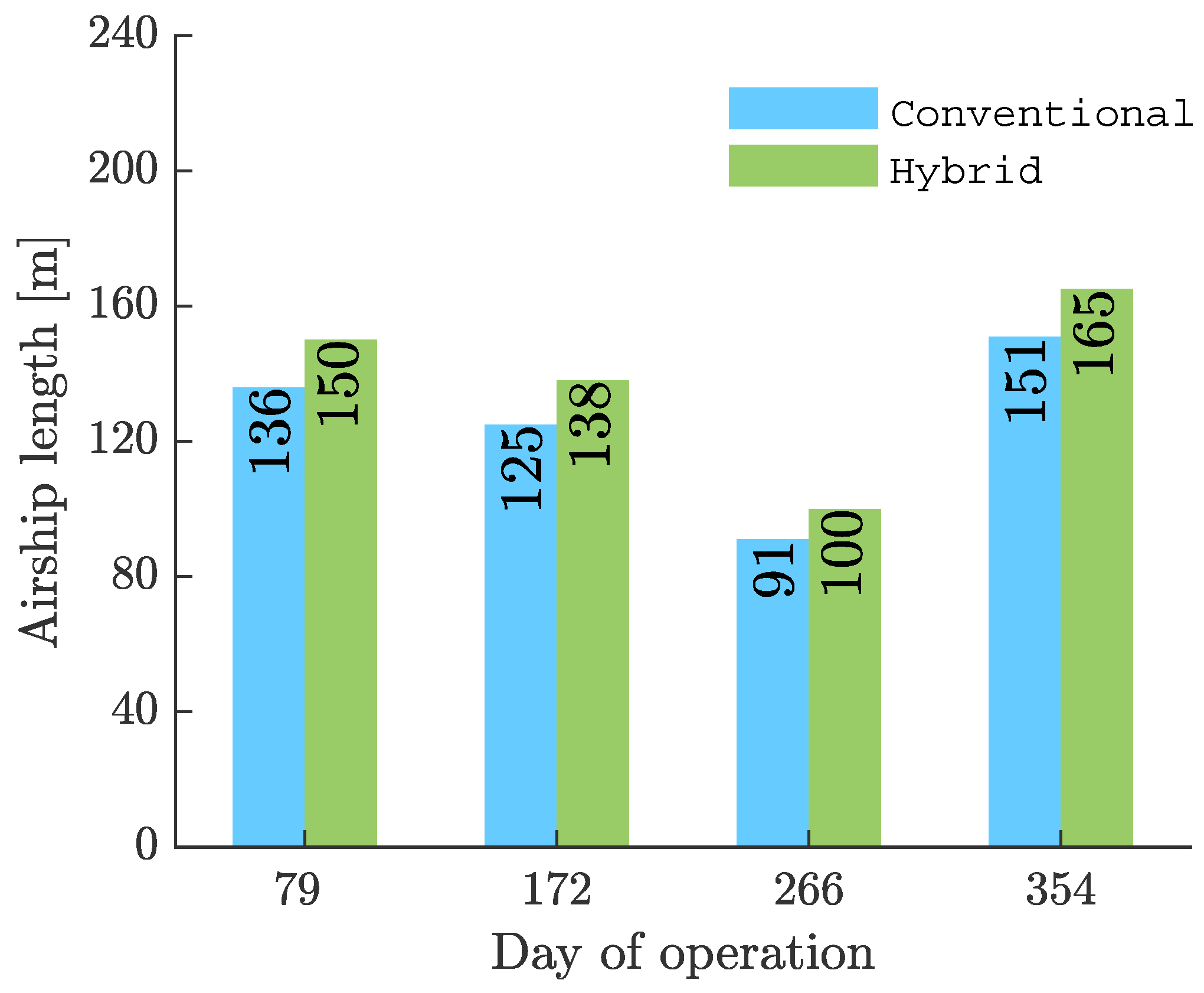
The rest of the data concerning the conventional airship optimal solutions are exactly as desired, within the expected regions of the design space. However, in the case of the winged airship configuration, there seems to be no improvement whatsoever, in both, sizing and general performance. This is clearly evident in
Figure 18,
Figure 19,
Figure 20 and
Figure 21.
The addition of a wing to the conventional airship configuration has resulted in no reduction in the sizing of the airship envelope whatsoever. The optimal solutions for the winged airship are significantly larger and heavier in comparison with the conventional airship solutions. One possible reason for this could be the over estimation of the wing mass value that has been utilized in the present study. As there is no exact formula available for estimating the wing mass for airships, the current value utilized could result in a significantly higher estimate for the airship mass than might be true. This in turn affects other areas of the optimization study, as the requirement for lift and power generated shoots up.
Another immediate issue that presents itself is regarding the sizing of the wing. In terms of sizing of the winged airship, it can be seen that the optimal configurations obtained for the different seasons are abnormally large. This is especially notable in the magnitudes of the wing span for the four different configurations. While it suffices to say that wing spans in the range of 200m or above might not be practically feasible in terms of construction and other structural issues regarding feasibility, this problem can be resolved by further modifying and optimising the values of design variable ranges and other design constants such as the airfoil section used, etc. The airfoil section utilized for the present analysis (NACA 2312) was chosen rather arbitrarily, as it did not fall within the scope of the study to carry out further optimization in this aspect. As mentioned earlier, a simple modification in the range of the wing AR design variable, in turn reduced the optimal wing span magnitudes from over 300 m, to the range of 150–250 m. Further fine tuning of the smaller aspects of the optimization process could result in better, more feasible and accurate optimal solutions for the HB airship.
Additionally, there is the issue of accurate estimation of the interference drag data pertaining to the wing structure. For the present study, a factor of 1.15 was selected, considering the average value from existing data for aircraft. This may have easily resulted in an overestimation of the total drag estimate, in turn, affecting other areas of the study (such as power requirement) negatively.
The abnormally large magnitudes could also be explained as a result of the low wind speed values at the concerned operating altitudes, and the significantly large lift requirements as a result of the additional mass component due to the wing structure. Therefore, it suffices to say that the mass penalty induced due to the addition of the wing simply outweighs any possible benefits in terms of performance and stability, on the basis of the available optimal solutions. A comparison of the mass distribution of the components of the two airship configurations are given in
Figure 22,
Figure 23,
Figure 24 and
Figure 25.
On the basis of the solutions obtained in the present study, it may be concluded that the winged hybrid airship produces no significant advantage over the conventional airship configurations.
7. Conclusions
A methodology for the conceptual design of a stratospheric HB airship has been presented. A multi-disciplinary optimization (MDO) was performed, incorporating the five modules of the HB airship, which are geometry, aerodynamics, environment, energy and structures. Optimal configurations of the airship have been obtained for two configurations—conventional and winged. The MDO process was carried out for four different days of the year. These are spring solstice ( = 79, 20 March), summer solstice ( = 172, 21 June), autumn solstice ( = 266, 23 September) and winter solstice ( = 354, 21 December). Key results and output parameters have been discussed.
Although all the constraints have been satisfied within the desired range of accuracy, the final results for the different days of operation still leave much to be desired, especially in terms of sizing of the winged airships. The unusually large sizes of the hull and wing planform can be attributed to the requirement of further individual optimization of the design constants and variable ranges utilized in the present study, among other things. Additionally, incorporation of further modules of the winged hybrid airship will also add to the accuracy of the final optimal configurations, resulting in significantly better estimates of the final solutions. There is significant scope for further improvement to the MDO process that has been laid out in this study.
Future work could include the following improvements:
- 1.
Incorporate the selection of an appropriate airfoil for the wing, as a part of the MDO process. This would result in further optimization of the airfoil and wing resulting in more sophisticated solutions.
- 2.
Accurate aerodynamic module to estimate lift and drag of the complete winged airship system.
- 3.
Structural analysis, which includes aeroelastic effects, in order to determine the feasibility of the optimal configurations.
- 4.
Research work focusing on improvement of the wing mass estimation for HB airships.
- 5.
An additional thermal module could be added to study the effects of the thermal environment on key performance parameters.
- 6.
Control surface sizing and stability analysis to ensure a statically and dynamically stable system.
The optimal solutions for the winged hybrid airship were concluded to be inferior to the conventional airship solutions, as a result of the potential advantages of the winged configuration being outweighed by penalties induced by wing mass estimation and sizing concerns. However, the improvement of the MDO process, as explained above, could potentially result in HB airship configurations which can combine the added benefits of the wing structure, while outweighing the underlying disadvantages.
This study has laid out the groundwork for such future applications and improvements for the preliminary design of the HB airship. Further incorporation of additional areas of flight performance and analysis, can result in the development of accurate and sophisticated design configurations of the HB airship, in the preliminary stages itself. This can greatly enhance the design process and ensure development of sophisticated HB airships for a multitude of applications in the military and civil aviation industries.


