Review

10-Year Anniversary of the European Proximity Operations Simulator 2.0—Looking Back at Test Campaigns, Rendezvous Research and Facility Improvements †

German Space Operations Center, German Aerospace Center, Münchener Straße 20, 82234 Weßling, Germany
*
Author to whom correspondence should be addressed.
This paper is an extended version of our paper published in German Aerospace Congress 2020 (virtual).
Aerospace 2021, 8(9), 235; https://doi.org/10.3390/aerospace8090235
Submission received: 7 July 2021 / Revised: 19 August 2021 / Accepted: 19 August 2021 / Published: 24 August 2021
(This article belongs to the Section Astronautics & Space Science)

Abstract

:
Completed in 2009, the European Proximity Operations Simulator 2.0 (EPOS 2.0) succeeded EPOS 1.0 at the German Space Operations Center (GSOC). One of the many contributions the old EPOS 1.0 facility made to spaceflight rendezvous is the verification of the Jena-Optronik laser-based sensors used by the Automated Transfer Vehicle. While EPOS 2.0 builds upon its heritage, it is a completely new design aiming at considerably more complex rendezvous scenarios. During the last ten years, GSOC’s On-Orbit-Servicing & Autonomy group, who operates, maintains and evolves EPOS 2.0, has made numerous contributions to the field of uncooperative rendezvous, using EPOS as its primary tool. After general research in optical navigation in the early 2010s, the OOS group took a leading role in the DLR project “On-Orbit-Servicing End-to-End Simulation” in 2014. EPOS 2.0 served as the hardware in the loop simulator of the rendezvous phase and contributed substantially to the project’s remarkable success. Over the years, E2E has revealed demanding requirements, leading to numerous facility improvements and extensions. In addition to the OOS group’s research work, numerous and diverse open-loop test campaigns for industry and internal (DLR) customers have shaped the capabilities of EPOS 2.0 significantly.

1. Introduction: A Look Back

In 2009, located in a laboratory hall at the German Space Operations Center (GSOC), construction of the European Proximity Operations Simulator 2.0 (EPOS 2.0) was completed. EPOS 2.0 is a Hardware in the Loop (HIL) simulator for spacecraft rendezvous maneuvers. With its two industrial robots, with one on a linear rail, it moves as a possibly true-to-scale mock up of the target object and navigation sensors representing the chaser spacecraft, just as they would move relative to one another in orbit. EPOS 2.0 allows the testing of optical sensors, navigation algorithms and even on-board computers in the loop. It aims at the most complex scenarios, such as active debris removal or lifetime extension, including tumbling targets not equipped for rendezvous, non-eyesafe laser-based sensors and more.
Since its construction, GSOC’s On Orbit Servicing and Autonomy Group (OOS-Group) has operated, maintained and advanced the simulation facility. This group uses EPOS 2.0 for its own research and offers test campaigns to external customers. EPOS 2.0 was not the first rendezvous simulator at GSOC. EPOS 1.0 was built in the 1980s, in the very same laboratory hall. It supported many projects, one of the most prominent being tests of the Automated Transfer Vehicle (ATV)’s Light RADAR (LiDAR) sensors.
Thus, the German Aerospace Center (DLR) has, now, over three decades of experience with spacecraft rendezvous simulations, and recently the OOS-Group celebrated the 10 year anniversary of EPOS 2.0. This paper seizes the opportunity to take a look back at those 10 years. We describe the facility’s heritage and the design rationales, the OOS-Group’s rendezvous research and diverse test campaigns for customers in roughly chronological order. Some sections overlap or describe parallel activities. This is for the sake of thematic coherence. In this way, the relation between requirements and learning with facility improvements and extensions can be illustrated vividly.

2. Heritage: EPOS 1.0

One cannot look back at the last 10 years of EPOS 2.0 utilization without recognizing the heritage upon it was built. Between 1985 and 1998, DLR and the European Space Agency (ESA) jointly constructed the old HIL simulation facility European Proximity Operations Simulator 1.0 (EPOS 1.0) in the same laboratory at GSOC as its successor. The facility was to become a real time simulator for true-to-scale scenarios, mimicking the last few critical meters of Rendezvous and Docking (RvD) maneuvers [1].
The Dynamic Motion System, depicted in Figure 1, was a gantry robot that carried navigation sensors and other equipment representing the chaser. It could move the chaser in six Degrees-of-Freedom (DoF) within a working space of 12 × 3 × 2 m. The mock up of the target spacecraft, whether it was mere retroflectors or a full geometric model, was oriented by a stationary attitude table (Figure 2) designated Target Mount. It could tilt the target about 20 degrees in all directions. The Illumination Subsystem allowed illumination of the target from behind the chaser with a 5000 VA tungsten halogen lamp, while the Direct Sun Illuminator could illuminate the chaser sensor’s Field-of-View (FoV) with 350 VA. Finally, the Data Processing Subsystem was responsible for real time control of the facility [2].
EPOS 1.0 supported many noteworthy projects during its lifetime. In 1991, comparative sensor tests (MATRA, Saab and MBB) took place at EPOS 1.0. From 1997 to 1999, the facility supported the ATV Rendezvous Pre-development program for ESA. In 1998–2000, there was project EDISON, a distributed simulation over the Asynchronuous Transfer Mode network on behalf of the EU. At the beginning of the 21st century, from 2001 to 2006, tests of Automated Transfer Vehicle navigation sensors were carried out for ESA. In parallel, the same was done in the context of the H-II Transfer Vehicle for the Japan Aerospace Exploration Agency [3,4].

3. New Challenges: EPOS 2.0

While EPOS 1.0 was a remarkably powerful tool, it handled mainly cooperative rendezvous scenarios. However, since the beginning of the 21st century, the field of spacecraft RvD has to face completely new challenges, way beyond proven mission scenarios like (automated) docking to the International Space Station (ISS) with ATV [5] or the Space Shuttle [6].
In 2009, Iridium 33 and Kosmos 2251 collided in orbit. This was the first known collision between two satellites [7]. It generated an enormous amount of debris objects with lasting consequences for spaceflight in those orbits [8]. Although the danger of satellite collisions had been well known for a long time, this incident demonstrated impressively that the threat was real, as were the consequences. The need for actively removing non-operational spacecraft and other debris objects has never been more evident [9,10].
Scientific demands cause another rendezvous challenge: structures in space that are larger than what fits into a typical rocket fairing. In astronomy, space telescopes with large main mirrors could outclass Hubble [11]. To make such an undertaking cost effective, these large structures have to be assembled in orbit, preferably by unmanned spacecraft [12,13].
However, in general, the satellite market demands a more sustainable and cost effective way of spaceflight. Ideas (re-)emerged about in-orbit lifetime extension or even the in-orbit repair and upgrade of, e.g., expensive Geostationary Orbit (GEO) satellites [14,15,16]. For example, in a commercial program with national co-funding, a consortium lead by Kayser–Threde began to develop a spacecraft called Orbital Life Extension Vehicle (OLEV) that was supposed to rendezvous and dock with an attitude stabilized GEO satellite. After docking, it would serve as the GEO satellite’s attitude and orbit control system. Among other tasks, it would also be capable of repositioning the satellite to another slot [17].
Targeting Low Earth Orbit (LEO), DLR’s Space Agency started the Deutsche Orbitale Servicing Mission (DEOS), a technology demonstration mission funded by the German Federal Ministry of Economy and Technology. It had three main goals. (1) Capture a tumbling, non-cooperative satellite using a manipulator mounted on a free flying servicing satellite. (2) Demonstrate a servicing application (e.g., component replacement). (3) De-orbit the captured satellite within a pre-defined re-entry corridor. For that purpose, the space segment consisted of two spacecraft: one was to represent the non-cooperative client (though it was a fully capable satellite for experiments). The other, the so called servicer, was equipped with a robotic arm for manipulating the target [18].
Regardless of the specific use case, all of those On Orbit Servicing (OOS) scenarios include some sort of close range approach and possibly docking. Particularly if the target is non-cooperative, i.e., non-operational, a close range approach is a risky and difficult task. The target object does not provide any information about its state. Therefore, the chaser spacecraft has to rely on optical navigation sensors. However, the target was likely not designed with rendezvous in mind; thus, there are no retroreflectors or clearly defined markers. Highly reflective surface materials, like Multi-Layer Insulation (MLI), combined with extreme illumination conditions in orbit make optical navigation even more difficult. In many cases, the target may not be attitude stabilized and may even be even tumbling. As with cooperative rendezvous and docking, on-ground test and verification is vital [19].
However, the old EPOS 1.0 facility was not equipped to handle such complex scenarios. The requirements of these scenarios were, along with the old facility’s limitations, the design drivers for EPOS 2.0. It was to be built from standard industrial robotics hardware that is more modular and easier to maintain and replace. It should extend the rendezvous range to about 25 m with a 10× better accuracy. The facility should be able to simulate the aforementioned complex approach trajectories HIL with real sensors and on-board computer hardware. Realistic illumination conditions were mandatory [3,20,21].
Figure 3 gives an impression of EPOS 2.0 at about 2009. By comparing Figure 1 and Figure 2, it becomes clear how different the setup actually is. Two industrial robots with six DoF each carry sensors representing the chaser spacecraft and a possibly true-to-scale mock up of the target object. Robot 1 with a maximum payload of 100 kg is mounted on a 25 m linear rail. Robot 2 with a maximum payload of 240 kg is fixed on the laboratory floor. In principle, both can mimic chaser or target. However, only robot 2 can carry really heavy mock ups. Therefore, robot 1 mimics the chaser, and robot 2 mimics the target in the majority of simulation configurations.
The facility is carefully calibrated from the robot flange to robot flange, specifically taking into account the relative position and attitude between the chaser and target. The calibration also includes the linear rail through its full length.
All 13 DoF are controlled in real time by a three-level system, as illustrated in Figure 4. On level 3, controllers provided by the robot manufacturer take care of low level functions, such as calculating the joint angles and basic safety mechanisms. The second level, the Facility Monitoring and Control System (FMC) allows monitoring the facility as an integrated unit and also allows choosing the operational mode.
In asynchronous mode, the FMC can be provided with precalculated trajectories that can be reproduced as often as required. This is very useful for sensor verification with the same trajectory under different illumination conditions. In synchronous mode, the FMC receives commands in real time from level 1, the Application Control System (ACS). Here, any real-time applications can be executed, e.g., based on MATLAB/Simulink. This mode is useful for closed-loop simulations, where navigation sensor data is processed in real time and fed to a dynamics simulator, which, in turn, moves the robots just as the chaser and target would move in orbit.
In another mode, a hand-held device called a Manual Control Unit (MCU) can be used to move the robots on the facility level manually, from the control room or the laboratory. This mode is often used in the calibration of navigation cameras. Obtaining the right set of images of the calibration pattern is a question of experience and intuition and is, therefore, best done manually. See [22,23,24] for more details on the EPOS 2.0 system architecture.

4. Early Rendezvous Research with EPOS 2.0

As soon as EPOS 2.0 was operational, GSOC’s OOS-Group started research activities in multiple areas. In this section, works from 2009 to about 2014 are briefly summarized with an emphasis on EPOS 2.0. These research activities took place in parallel to the first test campaigns for external customers as outlined in Section 5 and Section 6.

4.1. Spacecraft Rendezvous

The very first simulation setup is depicted in Figure 5. It included a mock up of a typical GEO satellite’s apogee engine view. This was motivated by an OLEV-like scenario, in which the chaser would use the target’s apogee nozzle for docking. The mock up was mounted onto robot 1. Robot 2 carried a standard industrial b/w camera (Prosilica GC655) with a resolution of 640 × 480 [25].
Based on collected images from open-loop tests [25,26], a first image processing algorithm was implemented. This algorithm used a texture segmentation algorithm to find the mock up’s edges in the image, as illustrated in Figure 6. Calculating the edges’ intersections gives the mock up’s corner points. Comparing these corner points with a digital model of the target results in the six DoF relative pose [25,26,27].
Combining this algorithm with a dynamics simulator (Hill equations [28]), a Kalman filter [29], a simple guidance function and a PD controller [30] allowed the team to execute the first closed-loop simulation with EPOS 2.0. Beginning with stability tests at hold points at a fixed distance, the simulations were rapidly extended to full approach trajectories. Due to robot singularities—joint configurations that were impossible to reach—and working space limits, mapping the simulation into the laboratory was a tedious manual trial and error task. As a result, only a small set of different starting conditions and approach trajectories were used. The software was implemented completely on ACS level in MATLAB/Simulink with some C++ code encapsulated in s-functions [31,32,33].
As a next step, an additional navigation sensor complemented the industrial camera mounted on robot 2: the Camcube Photonic Mixer Device (PMD) camera from PMD-Technologies GmbH delivers range images of the scene by comparing the phases of actively emitted and modulated light with the backscattered echo [19,34]. An example image is depicted in Figure 7. This range image was fed to a planar Random Sample Consensus (RANSAC) algorithm [35] that fitted a plane onto the target’s surface in the range image to obtain its pose.
The OOS-Group’s early research work in spacecraft rendezvous culminated in fusing the results of the navigation camera and PMD camera pose estimation. While the 2D camera provided the lateral position and roll angle, the PMD camera contributed the distance as well as the pitch and yaw angles to the fused result. Thus, the approach simulations used both sensors at the same time, exploiting the strengths and mitigating the weaknesses [36].

4.2. First Scanning LiDAR Experiments

LiDAR represents a very useful sensor technology for spacecraft rendezvous. It has been routinely used in cooperative rendezvous and docking [5] and could make uncooperative rendezvous safer and more reliable. A scanning LiDAR has a laser beam scan the FoV and capture the backscattered light. By comparing emitted and backscattered light, an accurate estimate of the distance can be calculated.
The OOS-Group started to become familiar with this technology in 2013. As no affordable 3D scanner was available at that time, a 2D scanner (scanning in-plane) was extended by an additional axis to cover a 3D FoV. The test setup depicted in Figure 8 was used to collect point cloud data from the scanner for analysis and algorithm development [37]. This led to a pose initialization algorithm from unstructured point cloud data [38].

4.3. Contact Dynamics

The idea behind contact dynamics simulation is simple: upon a physical contact between target and chaser mock up in the laboratory, both spacecraft should behave in a physically correct manner in the laboratory, just as they would in space. However, the realization of contact dynamics simulation is considerably more difficult. In a nutshell: the non-zero latency between robot motion commands and measurements by a force torque sensor made it necessary to implement some kind of compliant device so that the facility was not damaged upon contact. Implementing such a compliant device is not trivial [22,25].
The first contact dynamics experiments were conducted at EPOS 2.0 in a one-dimensional way, letting a probe with a force/torque sensor touch a compliant metal shield [39,40,41]. This was later extended to more degrees of freedom, letting a custom rudimentary compliant probe with a force/torque sensor touch the insides of an apogee engine nozzle [42,43].
The current research (see Section 8) of the OOS-Group heavily focuses on spacecraft rendezvous, and thus contact dynamics is not pursued any longer.

4.4. Connection of External Dynamics Simulators

The ACS level of EPOS 2.0 provides a flexible and generic platform for any type of application that can command the robots on a facility level. In order to realize more complex test setups with software simulators on dedicated hardware, possibly from a customer, a first version of an external EPOS interface was implemented. Despite being a first prototype, an external source could be connected via UDP/IP, and the starting conditions could be realized automatically with accurate timing [24,44]. The know-how from this prototype should play a vital role in a more advanced version of this interface (see Section 8.3).

4.5. Multiobjective Optimization

During a guest scientist’s work in the OOS-Group, a multiobjective optimation algorithm for thruster management was applied to uncooperative rendezvous [45,46]. The software was integrated into the GNC system Simulink model and tested with EPOS 2.0 [47,48,49].

5. Sunlight, Lasers and the VIBANASS Tests

5.1. A Sunlight Simulator

In simulating rendezvous maneuvers involving optical navigation sensors, realistic illumination in power density and spectrum are mandatory. EPOS 1.0 had that capability, and, from the start, this extension was also planned for the new facility [3]. The first test campaigns for an external customer lay ahead and required proper sun simulation.
For that purpose, an ARRIMAX 18/12 theater spotlight is used at EPOS 2.0. This daylight spotlight uses a 12 kW metal vapor lamp to generate a spectrum quite similar to visible sunlight. At about a 7 m distance to the target, the power density from the spotlight reaches the magnitude typical in Earth’s orbit around the Sun. The spotlight is mounted on a 2 DoF yoke that is electrically steerable. Thus, the illumination direction can be fine-tuned easily [23,24].

5.2. Preparing for Lasers

Many navigation sensors for spacecraft rendezvous are laser-based and not eyesafe. The use of such sensor systems was expected for the upcoming test campaigns, and therefore the laboratory was prepared to handle lasers up to class 4, compliant with safety regulations.
Currently, a laser curtain separates the EPOS 2.0 part from the remaining laboratory hall used by another department. A dedicated safety circuit integrates all relevant safety mechanisms. This includes doors and shutters for all windows granting a glance into the laboratory as well as a master switch in the control room. Finally, this is integrated with the robot emergency stop safety circuit. Any non-eyesafe sensor must be connected to an interlock signal available at robot 1’s tool flange. The sensor can only be active if the interlock signal is active. Whenever any of the safety measures is not properly applied (open shutters, master switch off, etc.), the interlock signal cannot become active. In this way, EPOS 2.0 provides the maximum safety for testing laser-based navigation sensors without limiting the robot working space [23].

5.3. VIBANASS Test Campaigns

With a sunlight simulator and laser safety concept ready to use, the OOS-Group carried out its first test campaigns in the context of project VIsion-BAsed NAvigation Sensor System (VIBANASS).
VIBANASS was a Kayser–Threde development program with co-funding from the DLR and DLR’s Space Agency. It was conducted in cooperation with DLR’s Institute for Robotics and Mechatronics as well as GSOC [17].
The project aimed at developing a versatile and modular sensor system for relative spacecraft navigation. It consists of a Camera System with three radiation-tolerant 1024 × 1024 b/w cameras for far-, mid- and close-range navigation, as well as a wide-angle Target Illumination System with one or more laser diode arrays. The cameras can be configured for mono and stereo image acquisition. An electronics box provides image pre-processing capability [50].
Two test campaigns took place at EPOS 2.0: the first in 2011 with a breadboard model [50] and the second in early 2013 with a demonstrator model [51].
Figure 9 shows the general test setup. Robot 1 carried two Camera System units in stereo configuration, two Target Illumination System power supply units and laser arrays as well as other supporting equipment. Robot 2 carried a mock up of the apogee engine view of a GEO satellite, not unlike the mock up used by the OOS-Group during early spacecraft rendezvous research. The simulation setup corresponded to an OLEV-like scenario [51].
Reflected light not only from the grey laser curtain but also from the aluminum robot cell fence in the mock up’s background impaired the image quality in some situations. Pieces of black cloth covering spots with the highest reflectance mitigated the problem.
In 53 test cases with four different trajectories and five different illumination configurations, over 50,000 images were recorded.
Additionally, the team realized a simple closed-loop test. With a dynamics simulator, Kalman filter, guidance and controller from GSOC’s OOS-Group, image processing from the DLR’s Robotics and Mechatronics Institute and the sensor system from Kayser–Threde, it was possible to close the loop and conduct a series of successful approach maneuvers [51,52,53].

6. Teaching a Robot to Tumble: The DEOS Tests

In the context of DEOS (see Section 3) project phase B2, rendezvous sensors were tested at EPOS 2.0 in 2013 for former EADS Astrium.
The mock up used in this test campaign was special. Until this point, EPOS 2.0 had only seen widely two-dimensional GEO mock ups. The DEOS target mock up, however, had a highly three-dimensional shape with a hexagonal body and a tower, including a dummy docking mechanism. It could be mounted in two ways: front side and back side. A LED pattern for navigation could optionally be mounted to the front side (see Figure 10), as well as a sheet of real MLI (see Figure 11). Construction of the mock up took place in loop with the OOS-Group, to ensure that robot 2 could handle its relatively high inertia.
Robot 1 represented the chaser with two different sensors. A classical 2D camera and a scanning LiDAR breadboard from Jena Optronik. Additionally, an LED-based (non-laser) illumination system allowed the camera to operate in the absence of sunlight. Figure 12 shows the sensors with the supporting equipment attached to robot 1.
During the test campaign, sensor data could be collected in numerous test cases. Many combinations of sun illumination configuration, mock up configuration (back/front, MLI/no MLI, LED pattern active/inactive) and different trajectories could be covered.
The OOS-Group gained valuable experience during this interesting test campaign:
  • The numerous trajectories for the open-loop tests were mainly derived from actual dynamics simulations and provided by EADS Astrium. In many test cases, the target mock up was tumbling, in strong contrast to the attitude stabilized GEO scenarios up to this point. Mapping these trajectories to EPOS 2.0 was found to be difficult. Robot joint limits and particularly the so-called singularity—joint configurations that the robot could not reach due to mathematical reasons—required the development of an optimization algorithm that allowed mapping the trajectories in a semi-automated way on a trial and error basis. This was not a perfect solution but was the foundation for considerable improvements at a later time.
  • The fact that robot 2 could rotate the mock up through only two revolutions about its symmetry axis at this time limited the duration of the tumbling trajectories considerably.
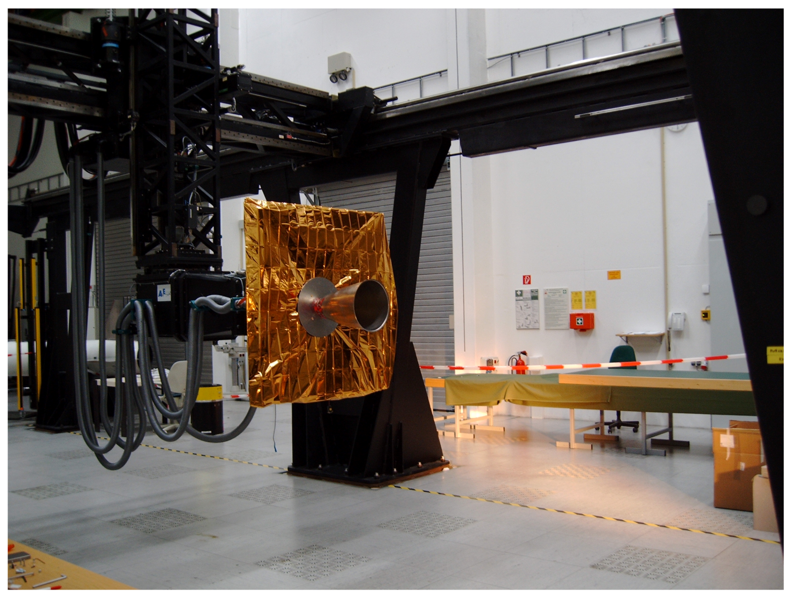
  • As already mentioned, many trajectories included a tumbling target and active laser-based sensors. The shutters of all windows granting a glance into the laboratory had to be closed. It proved difficult for the EPOS operator to properly monitor the robots, especially at close range, with the two available surveillance cameras alone.
  • In some cases, the laser curtain and the robot cell fence in the background of the target were too bright in the navigation camera images. Again, pieces of black cloth solved the problem.

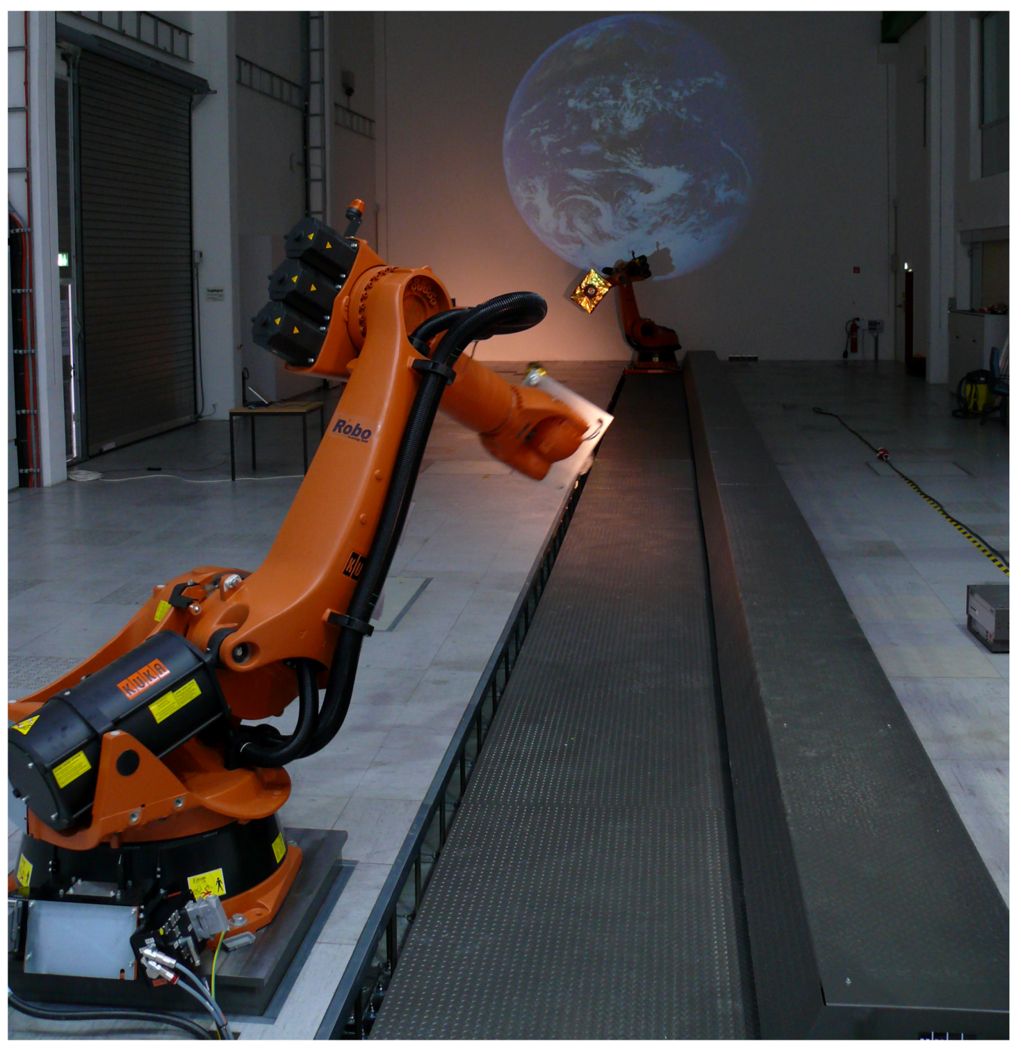
7. The Moon in the EPOS Lab: The Fosternav Tests

In the European Union (EU) project Flash Optical Sensor for Terrain Relative Robotic Navigation (FOSTER2NAV) a 3D flash LiDAR was developed. This sensor was not primarily designed for spacecraft rendezvous navigation but rather for lander applications. In 2014, the OOS-Group supported testing of the sensor on EPOS 2.0 for DLR’s Institute of Space Systems as part of a series of tests [54].
As usual, the sensor was mounted on robot 1, including supporting equipment, see Figure 13. Two different mock ups served as the target: the GEO mock up used in early research with the facility (see Section 4) and a large (several meters wide) stationary board that was equipped with geometric primitives and mounted upright in the laboratory, oriented rectangularly with respect to the linear rail.
The test campaign encompassed primarily generic approach trajectories. Since the sensor aimed at lander applications, the approach velocity had to be considerably higher than during spacecraft rendezvous. In fact, robot 1 moved with a maximum velocity of 1.3 m/s and maximum acceleration along the linear rail in many test cases. As a result, the individual approach trajectories did not take longer than a couple of seconds.

8. Advanced Rendezvous Research in DLR’s OOS-E2E Project

8.1. OOS-E2E and EPOS 2.0

Since about 2014, the OOS-Group’s spacecraft rendezvous activities have been dominated by its contribution to DLR’s internal On Orbit Servicing End-to-End Simulation (OOS-E2E) project and its successor (2018–2020). OOS-E2E’s main idea is a holistic development of space and ground segment for a variety of OOS scenarios, involving inspection, rendezvous, capture, detumbling and de-orbiting phases. Both space and ground segment are to be verified continuously on a fully integrated end-to-end simulation environment, reaching from a real GSOC control room using real space operations infrastructure and tools, up to HIL simulators carrying real sensors and robotics equipment.
OOS-E2E combines the following subsystems, as illustrated in Figure 14:
The dynamics simulator provides the whole simulation with the real time state of chaser and target. The satellite bus includes on-board data handling as well as basic thermal and power subsystem simulation and connects all the other components making it the center of the setup. Both the dynamics simulator and satellite bus were developed by DLR’s Institute of System Dynamics and Control. The satellite bus is connected to GSOC’s satellite operations network infrastructure via a simulator of the communication line also provided by GSOC [55], mimicking delay, jitter and package loss. The satellite bus console, using standard GSOC satellite monitoring and control software, shows the satellite bus telemetry and allows sending telecommands to the whole space segment of the setup.
EPOS 2.0 serves as the rendezvous simulator and receives motion commands from the dynamics simulator. Robot 1 carries the rendezvous navigation sensors, which are connected to the rendezvous GNC system, which, in turn, calculates the force and torque commands and forwards them to the satellite bus. On-ground, the rendezvous console allows for monitoring and controlling the rendezvous GNC system. It consists of standard GSOC tools, extended by dedicated applications, such as a camera display for real time imaging from the navigation camera.
The capturing phase is simulated using a facility called OOS-Sim, developed and operated by DLR’s Robotics and Mechatronics Institute, where it is also located [56]. This simulator is similar to EPOS 2.0 but smaller and without a linear rail. Rather, it is optimized for the simulation of grasping and contact dynamics. One of the robots carries an additional seven DoF robotic arm with integrated torque sensors, representing the grasping payload of the chaser. Again, the robotics console allows for monitoring and controlling the robotic grasping system. This console supports two modes: autonomous grasping and operator in the loop. In the latter case, an operator in the control room uses a haptic feedback device to move the robot in space in real time [23,57].
As mentioned above, EPOS 2.0 serves as the rendezvous simulator for the rendezvous GNC system developed by the OOS-Group. It is now implemented as a C++ application and runs on a dedicated PC. It is based on gathered knowledge from early rendezvous research (see Section 4) but with a completely new and more mature implementation. The OOS-Group has been continually improved and extended to the current day, thereby, progressing toward innovative on-board rendezvous software [58].
In the OOS-E2E setup, robot 1 carries the 2D camera as well as a more powerful PMD camera [59,60,61,62,63,64]. The mock up from the DEOS test campaign serves as the target during OOS-E2E. Fortunately, it could be borrowed for this research project. This also meant switching from a relatively simple GEO mock up (see Section 4) to a complex, three-dimensional target model.

8.2. RICADOS

Thanks to the OOS-E2E project’s exceptional success, a follow-up project, called Rendezvous, Inspection, CApture, Detumbling for Orbital Servicing (RICADOS), was started in 2018 and is now in its third year. While OOS-E2E focused on setting up the integrated simulation environment, implementing and testing all those numerous interfaces, even including a dedicated glass fiber for low-latency connection between GSOC and DLR’s Robotics and Mechatronics Institute in Oberpfaffenhofen, RICADOS allows building upon this work and focuses more on progressing the space segment.
With DLR’s Institute of Optical Systems, a fourth institute entered the project. This institute is responsible for the inspection phase in the simulated OOS scenarios. The target object may not be known precisely or at all. In that case, a digital model has to be generated during a mid-range fly-around. With this model, a close approach is possible safely and precisely as well as grasping of the target. The EPOS 2.0 robot 1 carries a stereo camera system from the Institute of Optical Systems alongside the rendezvous navigation sensors. This camera system delivers the required data in the telemetry for the on-ground generation of a digital target model [65].
Concerning the rendezvous GNC system, almost all components, may it be guidance, navigation filter, or pose estimation are being improved in RICADOS. Using PMD and a 2D camera in tandem by fusing their pose estimation results, robustness for the approach could be improved. In contrast to the sensor fusion mentioned in Section 4, this method is much more sophisticated and flexible [66]. The single navigation camera is about to be replaced by a pair of mid- and close-range cameras, to better handle very large and very small distances in the laboratory. Moreover, a Livox Mid-40 scanning LiDAR is installed and integrated into the rendezvous GNC system, at first primarily for providing distance and Line of Sight (LoS) data for the model-less fly-around during the inspection phase.
EPOS 2.0 is now part of an agile development process based on the Scrum framework [67], in which the ground and space segment, as well as the whole simulation environment are enhanced and extended continuously, keeping the system in a working state all the time. The OOS-Group executes routine local rendezvous tests every week, in addition to many ad hoc tests for supporting the development of new features. On a bi-weekly basis, the whole RICADOS setup is tested, that is to say, an OOS mission is flown.

8.3. Making EPOS fit for E2E

With OOS-E2E, EPOS 2.0 had to face new requirements and challenges. This has inspired many enhancements and improvements, especially in the years 2014–2016.
It became evident during past test campaigns that the grey laser curtain and the robot safety fence in the background of the target mock up reduced the realism of the collected navigation camera images considerably. This was also expected for OOS-E2E. The OOS-Group solved this problem by installing a theater curtain made from deep black molton cloth as well as a black floorcloth in a u-shape around robot 2. Moreover, the robot itself was covered in multiple pieces of tailored covers from the same material, without influencing the robot’s working space in any way. Figure 15 shows the background curtain and robot dress. Figure 16 makes clear how effective this improvement is. Especially at a closer distance, the background is deep black, and the target appears floating freely in space.
With intense usage of EPOS 2.0 for internal research and the increasing complexity of the sensor setup for the rendezvous GNC system, preparing robot 1 for an external customer became a time-consuming task. Sensors, power supplies, network equipment and cabling would have to be removed before and reinstalled after every test campaign. Therefore, the OOS-Group had a light-weight, ultra-stiff carbon fiber optical breadboard manufactured, which was installed on robot 1, as depicted in Figure 17. On this breadboard, all the sensors, power supplies and supporting equipment are mounted permanently. The whole breadboard can be removed in a matter of minutes due to the minimum number of electrical and mechanical connections between the breadboard and robot.
Right from the beginning of OOS-E2E, it was clear that EPOS 2.0 would have to handle a closed-loop and highly distributed simulation up to a close distance between both robots. In this situation, it is surprisingly difficult to judge the situation from a single visual perspective alone. Multiple different perspectives in the form of surveillance cameras are needed. The two available cameras at the time OOS-E2E began were not sufficient. Therefore, two additional steerable cameras were installed at different spots in the laboratory hall. Additionally, four dedicated PC monitors were mounted right next to the position of the operator in the EPOS 2.0 control room, to make monitoring from all perspectives at the same time easy and convenient. In this way, the facility can be protected from damage, especially during the testing of new features and in debugging sessions.
Up to this point, simulating a tumbling target with EPOS 2.0 was restricted to about 720 degrees, due to the robot joint limits. This, of course, made longer closed-loop simulations with a tumbling target impossible. Fortunately, the joints responsible for a spinning and tumbling movement could be configured to turn numerous revolutions (before they must be turned back). In that way, depending on the tumbling rate, multi-hour simulation scenarios with tumbling targets can be simulated with EPOS 2.0.
The distributed nature of the OOS-E2E setup brought along another problem: How to connect an external dynamics simulator to EPOS 2.0 safely? The first experiments had been conducted during early research work [44], see Section 4. For OOS-E2E, a much more capable interface was needed. It had to solve a variety of problems:
  • The dynamics simulation worked in Earth Center Inertial (ECI) coordinates, while, in the laboratory, only the relative pose can be realized reasonably.
  • Robot joint singularities and work space limits set boundaries to the possible set of fixed transformations from ECI to laboratory coordinates. A trial-and-error approach for each trajectory, as used up to this point, was not practical nor feasible for a complex closed-loop simulation.
  • The realization of the starting conditions in a distributed simulation was a real challenge. It was not possible to synchronize the whole setup, including another HIL simulator and the whole GSOC satellite operations infrastructure to EPOS 2.0 and then start everything exactly at the same time. The robots can not realize a specific state with non-zero velocity at once. Finally, in development work, a solution that required all subsystems to coordinate in such a way was not practical and would have been very fragile.
  • Simply connecting the robots to an external simulator leaves the facility vulnerable to any software bugs or human error. In closed-loop simulations anything can happen. An unstable control loop may accelerate the robots smoothly and cause a collision.
As a solution, the so called ExtEPOS interface was developed. It runs on ACS level (see Section 3) as a Simulink model. External simulation sources provide ExtEPOS with the states of chaser and target via UDP/IP. ExtEPOS combines a parameterizable mapping from any arbitrary coordinate frame into the laboratory with a real-time robot joint optimization that constantly uses all 13 DoF (six of each robot plus one of the linear rail) for circumventing robot singularities and working space limits. A clutch-like mechanism realizes the starting conditions: the robots constantly strive for following the desired trajectory. Upon simulation startup, the robots asymptotically approach this trajectory until they are engaged and actually follow the commanded trajectory.
This solution does not require any trigger signals or common time base with the external simulator and also implements speed limits as a side effect, which the robots will not violate regardless of the external simulator’s commands. Finally, ExtEPOS implements a simple collision detection algorithm that gracefully stops the robots if a collision is imminent and allows them to resume if no collision is further expected due to changed commands from the external simulator [68]. ExtEPOS has become the de facto standard for closed-loop simulations with EPOS 2.0.

8.4. On-Board Computer in the Loop

The OOS-Group is also involved in the DLR project Scalable On-board Computing for Space Avionics (ScOSA). This project aims at developing a modern, high-performance on-board computer. It is a multi-node system with high performance nodes built from commercial off-the-shelf components and with high reliability nodes based on space-proven hardware [69]. A Fault Detection, Isolation and Recovery (FDIR) mechanism detects failing nodes and automatically migrates tasks to working nodes [69].
The ScOSA platform is the on-board target system for the OOS-Group’s development work [70]. Specifically, a ScOSA breadboard model runs the rendezvous GNC system with a subset of features and directly connects to the ExtEPOS interface. No modifications on the EPOS 2.0 side are necessary, which demonstrates its flexibility after all the aforementioned improvements. In fact, with this setup, an on-board computer is in the loop. From the facility’s perspective, it could be an engineering or even a flight model.

9. GEO Again: SpaceTug

In parallel to OOS-E2E and RICADOS, the OOS-Group supported multiple test campaigns on EPOS 2.0. The first: SpaceTug.
SpaceTug was a project of Airbus Defence and Space. It aimed at rendezvous and docking with a GEO satellite for lifetime extension, upgrades or other types of services. Thus, after the test campaign in the context of the LEO scenario DEOS for EADS Astrium (now Airbus Defence and Space), EPOS 2.0 was awaiting another GEO scenario in 2017.
For the test campaign, robot 1 carried a 2D navigation camera and an engineering model of Jena Optronik GmbH’s RVS©3000 scanning LiDAR sensor (with serial number 1). Robot 2 did not carry anything, since the satellite mock up to be used—the largest up until now—was too massive for the robot. This meant that the mock up could not be positioned accurately by the robot in the laboratory. However, the trajectories to be simulated were relatively simple approach maneuvers where the target did not have to move at all.
Therefore, the target mock up was positioned directly on the laboratory floor across the linear rail, as shown in Figure 18. Airbus Defence and Space conceived a method to calibrate the mock up’s position and attitude in the laboratory. Before the tests, a probe was mounted to robot 1. By manually moving robot 1, the probe’s tip touched well defined reference points on the mock up one after another. At each point, the tip’s position in the laboratory was logged. Combining mock up reference points with the logged positions resulted in a sufficiently accurate estimate of the mock up’s position and attitude in the laboratory.
Overall, data from 14 trajectories, combined with different illumination angles and even total darkness, were collected.

10. Welcome Back Serial Number One: Testing RVS3000

In 2018, Jena-Optronik returned to EPOS 2.0 for a dedicated test of the RVS©3000 LiDAR sensor engineering model.
The test setup was comparatively simple. As shown in Figure 19, robot 1 carried the single box LiDAR sensor. Robot 2’s tool flange was equipped with a retro reflector pattern that would echo the laser beam back to its source.
The tests included dynamic and static trajectories with Line-of-Sight changes. Different illumination angles were tested as well as total darkness.

11. Going Beyond Earth Orbit: Mars Sample Return

In 2019, EPOS 2.0 was used for a very interesting test campaign for Airbus Defence and Space that barely had anything to do with OOS. This test campaign took place in the context of Mars Sample Return (MSR) phase B1 [71]. MSR is a joint mission by ESA and NASA with the goal of returning soil samples from the Red Planet back to Earth [72]. A rover will collect these samples on the surface of Mars. The Mars Ascent Vehicle will launch the Orbiting Sample Container into orbit, where ESA’s Earth Return Orbiter will rendezvous with it and bring it back to Earth.
The campaign aimed at testing mainly image acquisition and image processing, running on a LEON3 processor. The setup included a representative custom-of-the-shelf camera and two 3D-printed white mock ups of the Orbiting Sample Container (OS). One true-to-scale, the other 1:4. Both were probably the smallest mock ups ever used on EPOS 2.0. They were even smaller than robot 2’s adapter flange, which made it necessary to cover it with some molton cloth, to avoid a bright background in the images of the navigation camera. Figure 20 shows the test setup.
Using scaled and true-to-scale mock ups, approach trajectories spanned 80 m to 0.8 m distance. The numerous test cases varied in the mock up’s attitude motion and illumination conditions. Figure 21 shows images of the navigation camera during the approach. The background appears deep black, although the robot’s adapter plate is not completely invisible.
This test campaign, along with the FOSTER2NAV tests show that EPOS 2.0 is a versatile tool that can be used in a variety of scenarios, not restricted to OOS.

12. Conclusion: A Look Ahead

During the past ten years, EPOS 2.0 has supported various projects for external customers. Reaching from a LEO scenario with DEOS, GEO scenarios with VIBANASS and SpaceTug, to a Moon lander scenario with FOSTER2NAV and finally even to Mars in the MSR test campaign. The OOS-Group advanced from early rendezvous research with a simple setup, to a huge distributed OOS scenario. Alongside all these projects and research activities, EPOS 2.0 has evolved into a highly flexible and capable tool. Extended with laser safety measures, sunlight and space background simulation, sophisticated surveillance capabilities, real time robot joint optimization and more.
With all these enhancements and advanced knowledge about rendezvous GNC and HIL simulation, the OOS-Group is looking ahead toward new challenges in the immediate future. RICADOS++, a successor project of RICADOS, is expected to start in 2021. It will aim at increasing the overall suitability of space and ground segment for real space applications, while not neglecting the advancement of the simulation infrastructure. For EPOS 2.0, multiple test campaigns have already been scheduled. Some of those will be the first closed-loop tests for external customers. In this way, customers will profit from the various knowledge gained during OOS-E2E and RICADOS. In turn, EPOS 2.0 will profit from the challenging needs of those test campaigns and of RICADOS++.

Author Contributions

All authors were directly involved in operating EPOS in general as well as reviewing and editing the paper. F.R. wrote the original draft. He contributed to the project administration of various test campaigns from the technical perspective since 2011. He made substantial contributions to facility improvements (sensor assembly and external interface). He served as laser safety officer on the DLR side during test campaigns. H.F. was responsible for the project administration of many of the test campaigns as head of the OOS group. She has contributed to test campaigns since 2011. She made substantial contributions to the facility improvements (space background). She served as backup laser safety officer. E.-A.R. has contributed to test campaigns since 2016. M.B. has contributed to test campaigns since 2019. He organized the 12 year maintenance, including a full-scale facility calibration. All authors have read and agreed to the published version of the manuscript.

Funding

This work received no external funding.

Institutional Review Board Statement

Not applicable.

Informed Consent Statement

Not applicable.

Acknowledgments

EPOS 2.0’s success depends on the contribution of numerous dedicated people. Many students and PhD candidates have enriched EPOS 2.0 with their research and development work. We thank our customers for their trust and for all the interesting and fun test campaigns. During the facility’s conception, the cooperation with DLR’s Robotics and Mechatronics Institute was invaluable. The outstanding work of our colleagues from Robo Technology GmbH, who did the majority of design and construction of the simulation facility, is something we profit from every day. We have to thank our colleagues Tilman Wimmer for his dedication during the early years of EPOS 2.0 and Christian Mietner, who continues to support us with his vast experience and technical dexterity. Finally, special thanks go to the late Toralf Boge, former head of the OOS-Group, without whom neither EPOS 2.0 nor our team would be what it is today.

Conflicts of Interest

The authors declare no conflict of interest.

References

  1. Zunker, H.; Backhaus, H. Laser Based Rendezvous Sensors in Test on the European Proximity Operations Simulator. In Proceedings of the AIAA Guidance, Navigation and Control Conference, Hilton Head Island, SC, USA, 10–12 August 1992. [Google Scholar]
  2. Boge, T.; Schreutelkamp. A New Commanding and Control Environment for Rendezvous and Docking Simulations at the EPOS-Facility. In Proceedings of the International Workshop on Simulation for European Space Programmes, Noordwijk, The Netherlands, 12–14 November 2002. [Google Scholar]
  3. Boge, T.; Rupp, T.; Landzettel, K.; Wimmer, T.; Mietner, C.; Bosse, J.; Thaler, B. Hardware in the Loop Simulator für Rendezvous und Docking Manöver. In Proceedings of the German Aerospace Congress, Aachen, Germany, 8–10 September 2009. [Google Scholar]
  4. Rupp, T.; Boge, T.; Kiehling, R.; Sellmaier, F. Flight Dynamics Challenges of the German On-Orbit Servicing Mission DEOS. In Proceedings of the International Symposium on Space Flight Dynamics, Toulouse, France, 28 September–2 October 2009. [Google Scholar]
  5. Personne, G.; Lopez-Y-Diaz, A.; Delpy, P. ATV GNC Synthesis: Overal Design, Operations and Main Performances. In Proceedings of the International ESA Conference on Guidance, Navigation and Control Systems, Loutraki, Greece, 17–20 October 2005. [Google Scholar]
  6. Goodman, J.L. History of Space Shuttle Rendezvous and Proximity Operations. J. Spacecr. Rocket. 2006, 43, 944–959. [Google Scholar] [CrossRef]
  7. Kelso, T. Analysis of the Iridium 33-Cosmos 2251 Collision. Adv. Astronaut. Sci. 2010, 135, 1099–1112. [Google Scholar]
  8. Pardini, C.; Anselmo, L. Physical Properties and Long-term Evolution of the Debris Clouds Produced by Two Catastrophic Collision in Earth Orbit. Adv. Space Res. 2011, 48, 557–569. [Google Scholar] [CrossRef]
  9. Nishida, S.I.; Kawamoto, S.; Okawa, Y.; Terui, F.; Kitamura, S. Space Debris Removal System using a Small Satellite. Acta Astronaut. 2009, 65, 95–102. [Google Scholar] [CrossRef]
  10. Bonnal, C.; Ruault, J.M.; Desjean, M.C. Active Debri Removal: Recent Progress and Current Trends. Acta Astronaut. 2013, 85, 51–60. [Google Scholar] [CrossRef]
  11. MacEwen, H.A.; Lillie, C.F. Infrastructure for Large Space Telescopes. JATIS 2016, 2, 1–8. [Google Scholar] [CrossRef]
  12. Lillie, C.F. On-Orbit Assembly and Servicing of Future Space Observatories. In Proceedings of the Space Telescopes and Instrumentation I: Optical, Infrared, and Millimeter, International Society for Optics and Photonics, SPIE, Orlando, FL, USA, 14 June 2006; Volume 6265, pp. 767–778. [Google Scholar]
  13. Gralla, E.; Weck, O.D. Strategies for On-Orbit Assembly of Modular Spacecraft. J. Br. Interplanet. Soc. 2007, 60, 219–227. [Google Scholar]
  14. Ellery, A.; Kreisel, J.; Sommer, B. The Case for Robotic On-Orbit Servicing of Spacecraft: Spacecraft Reliability is a Myth. Acta Astronaut. 2008, 63, 632–648. [Google Scholar] [CrossRef]
  15. Stoll, E.; Letschnik, J.; Walter, U.; Artigas, J.; Kremer, P.; Preusche, C.; Hirzinger, G. On-Orbit Servicing. IEEE Robot. Autom. Mag. 2009, 16, 29–33. [Google Scholar] [CrossRef]
  16. Graham, A.; Kingston, J. Assessment of the Commercial Viability of Selected Options for On-Orbit Servicing (OOS). Acta Astronaut. 2015, 117, 38–48. [Google Scholar] [CrossRef]
  17. Kaiser, C.; Rank, P.; Landzettel, K.; Boge, T.; Turk, M. Vision Based Navigation for Future On-Orbit Servicing Missions. In Proceedings of the International Astronautical Congress, Cape Town, South Africa, 3–7 October 2011. [Google Scholar]
  18. Reintsema, D.; Thaeter, J.; Rathke, A.; Naumann, W.; Rank, P.; Sommer, J. DEOS—The German Robotics Approach to Secure and De-Orbit Malfunctioned Satellites from Low Earth Orbits. In Proceedings of the International Symposium on Artificial Intelligence, Robotics and Automation in Space, Sapporo, Japan, 29 August–1 September 2010. [Google Scholar]
  19. Benninghoff, H.; Boge, T.; Rems, F. Autonomous Navigation for On-Orbit Servicing. KI—KÜnstliche Intell. 2014, 28, 77–83. [Google Scholar] [CrossRef]
  20. Sellmaier, F.; Boge, T.; Spurmann, J.; Gully, S.; Rupp, T.; Huber, F. On-Orbit Servicing Missions: Challenges and Solutions for Spacecraft Operations. In Proceedings of the International Conference on Space Operations, Huntsville, AL, USA, 25–30 April 2010. [Google Scholar]
  21. Sellmaier, F.; Boge, T.; Spurmann, J. On-Orbit Servicing Missions at DLR/GSOC. In Proceedings of the International Astronautical Congress, Prague, Czech Republic, 27 September–1 October 2010. [Google Scholar]
  22. Boge, T.; Wimmer, T.; Ma, O.; Zebenay, M. EPOS–A Robotics-Based Hardware-in-the-Loop Simulator for Simulating Satellite RvD Operations. In Proceedings of the International Symposium on Artificial Intelligence, Robotics and Automation in Space, Sapporo, Japan, 29 August–1 September 2010. [Google Scholar]
  23. Benninghoff, H.; Rems, F.; Risse, E.A.; Mietner, C. European Proximity Operations Simulator 2.0 (EPOS)—A Robotic-Based Rendezvous and Docking Simulator. JLSRF 2017, 3. [Google Scholar] [CrossRef]
  24. Boge, T.; Benninghoff, H.; Zebenay, M.; Rems, F. Using Robots for Advanced Rendezvous and Docking Simulation. In Proceedings of the Simulation and EGSE Facilities for Space Programmes Conference, Noordwijk, The Netherlands, 25–27 September 2012. [Google Scholar]
  25. Boge, T.; Wimmer, T.; Ma, O.; Tzschichholz, T. EPOS—Using Robotics for RvD Simulation of On-Orbit Servicing Missions. In Proceedings of the AIAA Modeling and Simulation Technologies Conference, Toronto, Canada, 2–5 August 2010. [Google Scholar]
  26. Tzschichholz, T.; Boge, T. GNC Systems Development in Conjunction with a RvD Hardware-in-the-Loop Simulator. In Proceedings of the International Conference on Astrodynamics Tools and Techniques, Madrid, Spain, 3–6 May 2010. [Google Scholar]
  27. Tzschichholz, T.; Boge, T.; Benninghoff, H. A Flexible Image Processing Framework for Vision-based Navigation using Monocular Image Sensors. In Proceedings of the International ESA Conference on Guidance, Navigation & Control Systems, Carlsbad, Czech Republic, 5–10 June 2011. [Google Scholar]
  28. Fehse, W. Automated Rendezvous and Docking of Spacecraft; Cambridge Aerospace Series; Cambridge University Press: Washington, DC, USA, 2003. [Google Scholar]
  29. Kalman, R.E. A New Approach to Linear Filtering and Prediction Problems. Trans. ASME—J. Basic Eng. 1960, 83, 33–45. [Google Scholar] [CrossRef] [Green Version]
  30. Wertz, J.R. (Ed.) Spacecraft Attitude Determination and Control; Springer: Dordrecht, The Netherlands, 1978. [Google Scholar]
  31. Benninghoff, H.; Tschichholz, T.; Boge, T.; Rupp, T. Hardware-in-the-Loop Simulation of Rendezvous and Docking Maneuvers in On-Orbit Servicing Missions. In Proceedings of the International Symposium on Space Technology and Science, Okinawa, Japan, 5–12 June 2011. [Google Scholar]
  32. Boge, T.; Benninghoff, H.; Tzschichholz, T. Hardware-in-the-Loop Rendezvous Simulation using a Vision Based Sensor. In Proceedings of the International ESA Conference on Guidance, Navigation & Control Systems, Carlsbad, Czechia, 5–10 June 2011. [Google Scholar]
  33. Benninghoff, H.; Boge, T.; Tzschichholz, T. Hardware-in-the-Loop Rendezvous Simulation Involving an Autonomous Guidance, Navigation and Control System. In Proceedings of the IAA Conference on Dynamics and Control of Space Systems, Porto, Portugal, 19–21 March 2012. [Google Scholar]
  34. Boge, T.; Benninghoff, H.; Tzschichholz, T. Visual Navigation for On-Orbit Servicing Missions. In Proceedings of the International Conference on Spacecraft Formation Flying Missions and Technologies, Munich, Germany, 29–31 May 2013. [Google Scholar]
  35. Fischler, R.B.M. Random sample consensus: A paradigm for model fitting with applications to image analysis and automated cartography. Commun. ACM 1981, 24, 381–395. [Google Scholar] [CrossRef]
  36. Tzschichholz, T.; Boge, T.; Schilling, K. Relative Pose Estimation of Satellites using PMD-/CCD-sensor Data Fusion. Acta Astronaut. 2015, 109, 25–33. [Google Scholar] [CrossRef]
  37. Rems, F.; Fritz, S.; Boge, T. Breadboard Model of a 3D LiDAR Sensor for Real-time Pose Estimation of Spacecraft. In Proceedings of the International ESA Conference on Guidance, Navigation & Control Systems, Porto, Portugal, 2–6 June 2014. [Google Scholar]
  38. Rems, F.; González, J.A.M.; Boge, T.; Tuttas, S.; Stilla, U. Fast Initial Pose Estimation of Spacecraft from LiDAR Point Cloud Data. In Proceedings of the Symposium on Advanced Space Technologies in Robotics and Automation, Noordwijk, The Netherlands, 11–13 May 2015. [Google Scholar]
  39. Zebenay, M.; Lampariello, R.; Boge, T.; Krenn, R. Control Strategy of Hardware-in-the-Loop Simulator EPOS 2.0 for Autonomous Docking Verification. In Proceedings of the Annual Meeting of the International Association of Applied Mathematics and Mechanics, Graz, Austria, 18–21 April 2011. [Google Scholar]
  40. Zebenay, M.; Lampariello, R.; Boge, T.; Choukroun, D. A New Contact Dynamics Model Tool for Hardware-in-the-Loop Docking Simulation. In Proceedings of the International Symposium on Artificial Intelligence, Robotics and Automation in Space, Torino, Italy, 4–7 September 2012. [Google Scholar]
  41. Zebenay, M.; Boge, T.; Krenn, R.; Choukroun, D. Analytical and Experimental Stability Investigation of a Hardware-in-the-Loop Satellite Docking Simulator. J. Aerosp. Eng. 2015, 229, 666–681. [Google Scholar] [CrossRef] [Green Version]
  42. Zebenay, M.; Boge, T.; Choukroun, D. Modelling, Stability Analysis, and Testing of a Hybrid Docking Simulator. In Proceedings of the AIAA Guidance Navigation and Control Conference, Boston, MA, USA, 19–22 August 2013. [Google Scholar]
  43. Zebenay, M.; Boge, T.; Lampariello, R.; Choukroun, D. Satellite Docking Simulation Based on HIL Hybrid Contact Model. In Proceedings of the Symposium on Advanced Space Technologies in Robotics and Automation, Noordwijk, The Netherlands, 15–17 May 2013. [Google Scholar]
  44. Rems, F. Integrating the European Proximity Operations Simulator with the Formation Flying Testbed. In Proceedings of the German Aerospace Congress, Berlin, Germany, 10–12 September 2012. [Google Scholar]
  45. dos Santos, W.G.; Rocco, E.M.; Boge, T. Design of a Linear Time-invariant Control System Based on a Multiobjective Optimization Approach. Comput. Appl. Math. 2015, 35, 789–801. [Google Scholar]
  46. dos Santos, W.G.; Rocco, E.M.; Boge, T.; Benninghoff, H.; Rems, F. Multi-objective Optimization Applied to Real-time Command Problem of Spacecraft Thrusters. J. Spacecr. Rockets 2015, 52, 1407–1416. [Google Scholar] [CrossRef]
  47. dos Santos, W.G.; Rocco, E.M.; Boge, T.; Benninghoff, H.; Rems, F. A Novel Solution for the Spacecraft Mixed Actuators Problem Based on a Multiobjective Optimization Method. In Proceedings of the International Symposium on Space Flight Dynamics, Munich, Germany, 19–23 October 2015. [Google Scholar]
  48. dos Santos, W.G.; Rocco, E.M.; Boge, T.; Rems, F.; Benninghoff, H. Discrete Multiobjective Optimization Methodology Applied to the Mixed Actuators Problem and Tested in a Hardware-in-the-Loop Rendevzous Simulator. In Proceedings of the AIAA Guidance, Navigation, and Control Conference, Kissimmee, FL, USA, 5–9 January 2015. [Google Scholar]
  49. dos Santos, W.G.; Rocco, E.M.; Boge, T.; Benninghoff, H.; Rems, F. Hardware-in-the-Loop Rendezvous Tests of a Novel Actuators Command Concept. J. Astronaut. Sci. 2016, 63, 287–307. [Google Scholar] [CrossRef]
  50. Mühlbauer, Q.; Richter, L.; Kaiser, C.; Hofmann, P. Robotics Space Systems and Subsystems for Advanced Future Programms. In Proceedings of the International Symposium on Artificial Intelligence, Robotics and Automation in Space, Turin, Italy, 4–7 September 2012. [Google Scholar]
  51. Mühlbauer, Q.; Rank, P.; Kaiser, C. On-ground Verification of VIBANASS (Vision Based Navigation Sensor System): Capabilities and Results. In Proceedings of the Symposium on Advanced Space Technologies in Robotics and Automation, Noordwijk, The Netherlands, 15–17 May 2013. [Google Scholar]
  52. Benninghoff, H.; Rems, F.; Boge, T. Development and Hardware-in-the-Loop Test of a Guidance, Navigation and Control System for On-Orbit Servicing. Acta Astronaut. 2014, 102, 67–80. [Google Scholar] [CrossRef]
  53. Boge, T.; Benninghoff, H. Rendezvous Simulation for On-Orbit Servicing Missions using Advanced Robotic Technology. In Proceedings of the International Symposium on Automatic Control in Space, Würzburg, Germany, 2–6 September 2013. [Google Scholar]
  54. Krüger, H.; Theil, S.; Sagliano, M.; Hartkopf, S. On-ground Testing of Optical Navigation Systems for Exploration Missions. In Proceedings of the International ESA Conference on Guidance, Navigation & Control Systems, Porto, Portugal, 2–6 June 2014. [Google Scholar]
  55. Weber, D.; Gnat, M.; Hauke, A.; Huber, F.; Acero, C.G. End-to-End Simulation of On-Orbit-Servicing: Technical Implementation of Communications. In Proceedings of the International Conference on Space Operations, Marseille, France, 28 May–1 June 2018. [Google Scholar]
  56. Artigas, J.; Stefano, M.D.; Rackl, W.; Lampariello, R.; Brunner, B.; Bertleff, W.; Burger, R.; Porges, O.; Giordano, A.; Borst, C.; et al. The OOS-SIM: An On-ground Simulation Facility for On-Orbit Servicing Robotic Operations. In Proceedings of the IEEE International Conference on Robotics and Automation, Seattle, WA, USA, 25–30 May 2015. [Google Scholar]
  57. Benninghoff, H.; Rems, F.; Risse, E.; Brunner, B.; Stelzer, M.; Krenn, R.; Reiner, M.; Stangl, C.; Gnat, M. End-to-End Simulation and Verification of GNC and Robotic Systems Considering Both Space Segment and Ground Segment. CEAS Space J. 2018, 10, 535–553. [Google Scholar] [CrossRef]
  58. Rems, F.; Risse, E.A.; Benninghoff, H. Rendezvous GNC-system for Autonomous Orbital Servicing of Uncooperative Targets. In Proceedings of the International ESA Conference on Guidance, Navigation & Control Systems, Salzburg, Austria, 29 May–2 June 2017. [Google Scholar]
  59. Klionovska, K.; Benninghoff, H. Visual Navigation for Rendezvous and Docking using PMD Camera. In Proceedings of the International Conference on Geographical Information Systems Theory, Applications and Management, Rome, Italy, 26–27 April 2016. [Google Scholar]
  60. Klionovska, K.; Benninghoff, H. Initial Pose Estimation using PMD Sensor during the Rendezvous Phase in On-Orbit Servicing Missions. In Proceedings of the AAAS/AIAAA Space Flight Mechanics Meeting, San Antonio, TX, USA, 5–9 February 2017. [Google Scholar]
  61. Klionovska, K.; Benninghoff, H.; Strobl, K.H. PMD Camera- and Hand-eye-calibration for On-Orbit Servicing Test Scenarios on the Ground. In Proceedings of the Symposium on Advanced Space Technologies in Robotics and Automation, Scheltema, Leiden, The Netherlands, 20–22 June 2017. [Google Scholar]
  62. Klionovska, K.; Ventura, J.; Benninghoff, H.; Huber, F. Close Range Tracking of an Uncooperative Space Target in a Sequence of PMD Images. In Proceedings of the IAA Conference on Space Situational Awareness, Orlando, FL, USA, 13–15 November 2017. [Google Scholar]
  63. Klionovska, K.; Ventura, J.; Benninghoff, H.; Huber, F. Close Range Tracking of an Uncooperative Target in a Sequence of Photonic Mixer Device (PMD) Images. Robotics 2018, 7, 5. [Google Scholar] [CrossRef] [Green Version]
  64. Klionovska, K.; Benninghoff, H.; Huber, F. More Accurate Pose Initialization with Redundant Measurements. In Proceedings of the International Joint Conference on Computer Vision, Imaging and Computer Graphics Theory and Applications, Prague, Czechia, 25–27 February 2019. [Google Scholar]
  65. Benninghoff, H.; Rems, F.; Risse, E.A.; Irmisch, P.; Ernst, I.; Brunner, B.; Stelzer, M.; Lampariello, R.; Krenn, R.; Reiner, M.; et al. RICADOS—Rendezvous, Inspection, Capturing and Detumbling by Orbital Servicing. In Proceedings of the International Conference on Astrodynamics Tools and Techniques, Weßling, Germany, 6–9 November 2018. [Google Scholar]
  66. Klionovska, K.; Benninghoff, H.; Risse, E.A.; Huber, F. Experimental Analysis of Measurements Fusion for Pose Estimation using PMD Sensor. In Proceedings of the Iberoamerican Congress on Pattern Recognition, Madrid, Spain, 19–22 November 2018. [Google Scholar]
  67. Rubin, K.S. Essential Scrum: A Practical Guide to the Most Popular Agile Process; Addison-Wesley: Ann Arbor, MI, USA, 2012. [Google Scholar]
  68. Rems, F. Robotic Verification of Spacecraft Rendezvous In-loop with Real-time Satellite Dynamics Simulation. In Proceedings of the German Aerospace Conference, Munich, Germany, 5–7 September 2017. [Google Scholar]
  69. Treudler, C.J.; Benninghoff, H.; Borchers, K.; Brunner, B.; Cremer, J.; Dumke, M.; Gärtner, T.; Höflinger, K.J.; Lüdtke, D.; Peng, T.; et al. ScOSA—Scalable On-Board Computing for Space Avionics. In Proceedings of the International Astronautical Congress, Bremen, Germany, 1–5 October 2018. [Google Scholar]
  70. Schwenk, K.; Ulmer, M.; Peng, T. ScOSA: Application Development for a High-performance Space Qualified Onboard Computing Platform. In High-Performance Computing in Geoscience and Remote Sensing, Proceedings of SPIE 10792, High-Performance Computing in Geoscience and Remote Sensing VIII, Berlin, Germany, 10–13 September 2018; SPIE: Berlin, Germany, 2018; Volume VIII. [Google Scholar]
  71. Burri, M.; Frei, H.; Rems, F.; Klionovska, K.; Risse, E.A.; Kanani, K.; Masson, A.; Falcoz, A. Mars Sample Return—Test Campaign for near Range Image Processing on European Proximity Operations Simulator. In Proceedings of the International ESA Conference on Guidance, Navigation & Control, Virtual, 22–25 June 2021. [Google Scholar]
  72. Joint Statement of Intent between the National Aeronautics and Space Administration and the European Space Agency on Mars Sample Return. 26 April 2018. Available online: https://mepag.jpl.nasa.gov/announcements/2018-04-26%NASA-ESA%SOI%(Signed).pdf (accessed on 23 August 2021).
Figure 1. EPOS 1.0 Dynamic Motion Subsystem.
Aerospace 08 00235 g001
Figure 2. EPOS 1.0 target mount.
Aerospace 08 00235 g002
Figure 3. EPOS 2.0 laboratory in 2009. Background: robot 1 mounted on a 25 m linear rail. Left: robot 2 fixed to the laboratory floor.
Aerospace 08 00235 g003
Figure 4. EPOS 2.0 control system overview.
Aerospace 08 00235 g004
Figure 5. GEO mockup mounted on robot 1.
Aerospace 08 00235 g005
Figure 6. Tracked egdes of GEO mockup under realistic illumination.
Aerospace 08 00235 g006
Figure 7. Range image captured with CamCube PMD camera.
Aerospace 08 00235 g007
Figure 8. Setup for LiDAR tests. Note that the contact probe for fully six DoF contact dynamics simulation is also mounted, because the tests were performed at about the same time.
Aerospace 08 00235 g008
Figure 9. Setup for the VIBANASS test campaign.
Aerospace 08 00235 g009
Figure 10. DEOS target mock up without MLI.
Aerospace 08 00235 g010
Figure 11. DEOS target mock up with golden MLI.
Aerospace 08 00235 g011
Figure 12. Sensor setup for the DEOS test campaign.
Aerospace 08 00235 g012
Figure 13. 3D flash LiDAR of project FOSTER2NAV mounted on robot 1 with the flange positioned horizontally. Supporting equipment at the robot base.
Aerospace 08 00235 g013
Figure 14. Overview of OOS-E2E simulation setup.
Aerospace 08 00235 g014
Figure 15. Background curtain and robot covered in molton cloth.
Aerospace 08 00235 g015
Figure 16. Images of the navigation camera at different distances with pose estimation result overlay.
Aerospace 08 00235 g016
Figure 17. Carbon fiber composite breadboard with rendezvous sensors mounted to robot 1. Right: power supplies, network switch and other supporting equipment. Center: standard camera, mid- and close range cameras and new PMD camera by Bluetechnix in white. Left: Livox Mid-40 scanning LiDAR.
Aerospace 08 00235 g017
Figure 18. Left: target GEO mock up stationary on the laboratory floor. Right: sensors mounted on robot 1.
Aerospace 08 00235 g018
Figure 19. RVS3000 mounted on robot 1.
Aerospace 08 00235 g019
Figure 20. True-to-scale target on robot 2 and navigation camera on robot 1.
Aerospace 08 00235 g020
Figure 21. Example images of navigation camera during approach at distances of 15, 10, 5 and 2 m.
Aerospace 08 00235 g021
Publisher’s Note: MDPI stays neutral with regard to jurisdictional claims in published maps and institutional affiliations.

