Article

FMI-Based Multi-Domain Simulation for an Aero-Engine Control System

College of Energy and Power Engineering, Nanjing University of Aeronautics and Astronautics, Nanjing 210016, China
*
Author to whom correspondence should be addressed.
Aerospace 2021, 8(7), 180; https://doi.org/10.3390/aerospace8070180
Submission received: 11 May 2021 / Revised: 23 June 2021 / Accepted: 29 June 2021 / Published: 2 July 2021
(This article belongs to the Special Issue Progress in Jet Engine Technology II)

Abstract

:
The simulation of an aero-engine control system involves numerous disciplines due to its complex functions and architecture, which generally consist of mechanical, hydraulic and electrical, and electronic systems. For each discipline, the modeling and simulation are usually dependent on different commercial software and tools, which makes the simulation, integration, and verification of system-level models very difficult. To meet this challenge, a multi-domain co-simulation method based on the Functional Mock-up Interface (FMI) standard is proposed to integrate models developed by different software or tools. The simulation and testing results demonstrate that multi-disciplinary model integration and cross-platform simulation based on the FMI standard can be realized for an aero-engine control system, which lays a foundation for high-fidelity control system design, simulation, integration, and testing.

1. Introduction

Simulation technology runs through the whole development cycle of an engine control system, which makes it possible to detect and verify the design error at an early stage of development. An aeroengine control system is composed of mechanical, hydraulic, electronic, and electrical components [1]. Each component is designed by a professional designer with different commercial simulations or platforms. Ultimately, those detailed component models must be integrated to verify the overall performance due to the impact of small variations [2]. However, due to the inconsistency of the solver, operating environment, and especially model interface of commercial simulation tools, it is difficult to integrate the component models into system-level models for high-precision co-simulation. In response to this issue, many methods have been proposed in the past decades.
NPSS (Numerical Propulsion System Simulation) [3], a numerical simulation tool for propulsion systems developed by NASA (National Aeronautics and Space Administration) Glenn in the 1990s, is based on scaling technology and CORBA (Common Object Request Broker Architecture) to realize distributed co-simulation of aeroengine multi-precision and multi-disciplinary models. Scaling technology can modify the interfaces between different components to connect components of different dimensions in series. CORBA [4] designs a set of interface and communication specifications, so that all software systems or tools that meet the specifications can be easily integrated into the CORBA system and to realize distributed co-simulation through network communication. Unfortunately, the implementation scheme relies on the tools based on NPSS and is not applicable to commercial simulation software. In addition, this tool only considers the co-simulation of engine components of different dimensions but ignores the multi-disciplinary co-simulation of control systems. The HLA [5] (High Level Architecture) was proposed by the Office of Modeling and Simulation of the United States Department of Defense. HLA introduces the framework technology structure of component-based distributed simulation. Its specification defines the interaction and communication between simulation components from three aspects: rules, interfaces, and object models to realize the interoperability and reuse of models. The development of the HLA system depends on RTI (Runtime Infrastructure), and many countries are actively developing their own RTI, which is conforming to the HLA specifications. In addition, HLA architecture is based on the high-level concept, which defines the framework of distributed simulation. However, the high-level concept does not set up and standardize the operation details of simulation models. Thus, it has less practical application in simulation. In this case, the 2010 European Development Information Plan (ITEA2) [6] proposed MODELISAR (Model-AUTOSAR integration to support vehicle Functional Mockup), which developed an FMI standard for the first time. FMI standardizes all simulation processes. According to this standard, all modeling and simulation software can export its models into FMU (Functional Mock-up Unit) files, and other software can parse and call these files. At present, the standard has been adopted by more than 110 types of commercial simulation software, including control system simulation software AMESim [7,8,9], Simulink [10], etc. and has gradually become a unified standard widely accepted.
In the past decades, the FMI-based co-simulation was widely used in the vehicle, vessel, and aerospace fields and has shown tremendous potential [11,12,13,14]. However, the application of this technology in the field of aero-engine control systems is still in the development stage. At present, most of the co-simulation for aero-engine is only for a certain component, such as a fuel actuator, which lacks the overall co-simulation modeling of engine control systems. Yu, et al. [7,15] adopted AMESim to build a fuel metering device of aeroengines, and the effect of the main design parameters of the metering device on the fuel metering characteristics was analyzed. Gu [16] built an engine cooling system based on AMESim to simulate the steady heater transfer and flow of engine cooling systems. A single spool gas was built using Modelica, which verified the validity of model [17]. Furthermore, the hardware-in-the-loop (HIL) simulation of aero-engine control system co-simulation has rarely been studied, which is a significant way to verify model and control logic [18,19].
Referring to the control system of a turbofan engine with a large bypass ratio, typical control system components, i.e., model, engine model, and control law model, are built using AMESim, Modelica [20,21], Simulink, and C language. Then, the integration and co-simulation of multidisciplinary models of control systems are realized based on FMI standards. Finally, the integration and verification are carried out on HIL platforms.

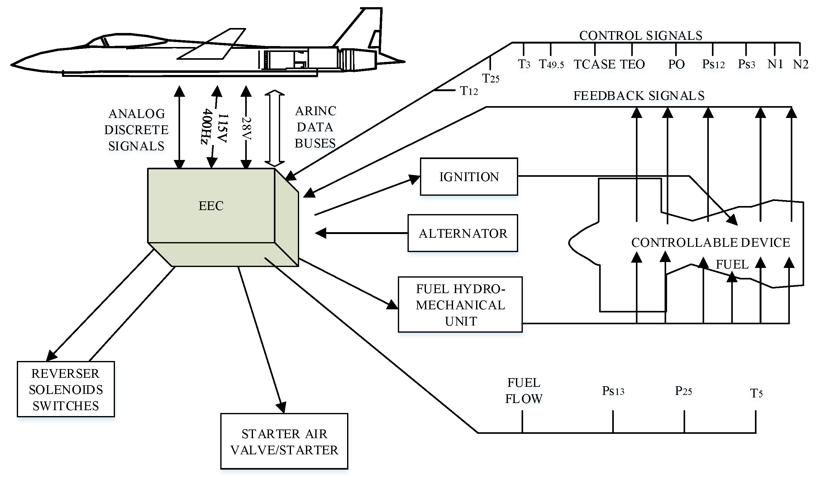
2. Modeling and Simulation of Aeroengine Control System Components
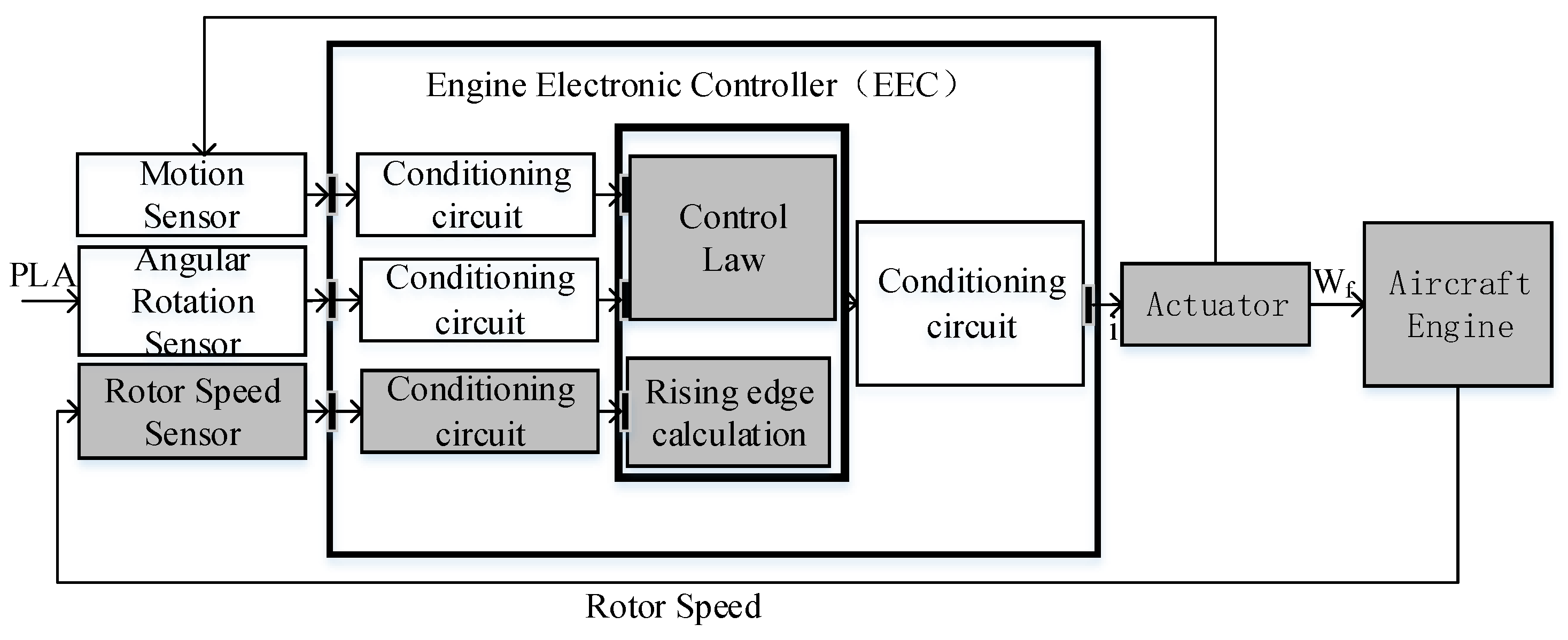
The structure diagram of a turbofan engine digital control system with a large bypass ratio is shown in Figure 1, which is generally adopted. The digital electronic controller (EEC) is the central component of the digital control system, which mainly includes a hardware circuit and software control logic. It receives the feedback signals from sensors and actuator and outputs a control command to the ignition device, startup device, and hydraulic machinery device after calculation. The fuel valve and exhaust valve of engines are controlled by the hydraulic mechanical device to make sure that engines meet the requirements of the safety and performance of aircraft.
In this paper, a closed-loop speed control system is designed based on the prototype of the numerical control system in Figure 1. The model structure is shown in Figure 2. The typical control components of the system (Gray Module in Figure 2) are selected to establish a multidisciplinary model, including rotor speed sensor, EEC conditioning circuit, fuel actuator, engine, and EEC rising edge calculation module and control law model. The main functions of each module are as follows:
(1)
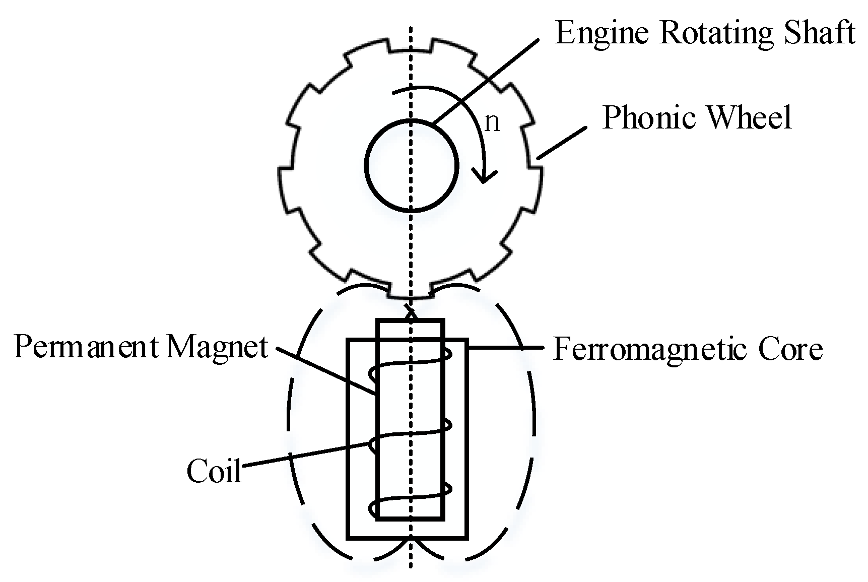
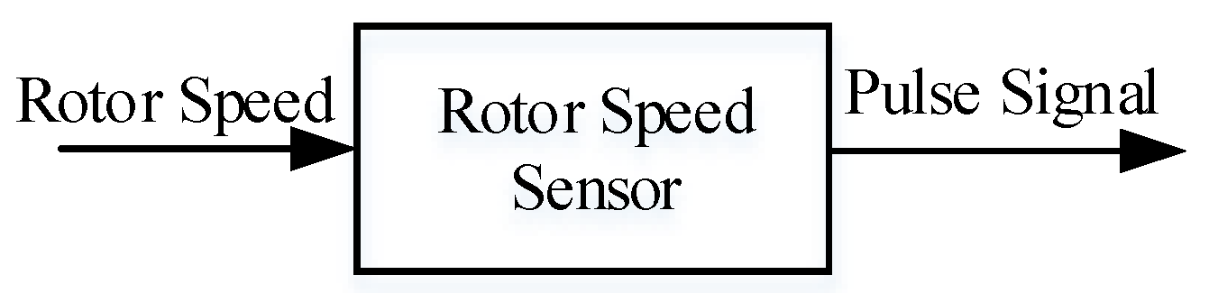
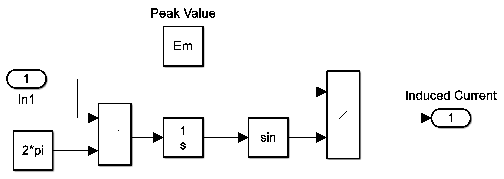
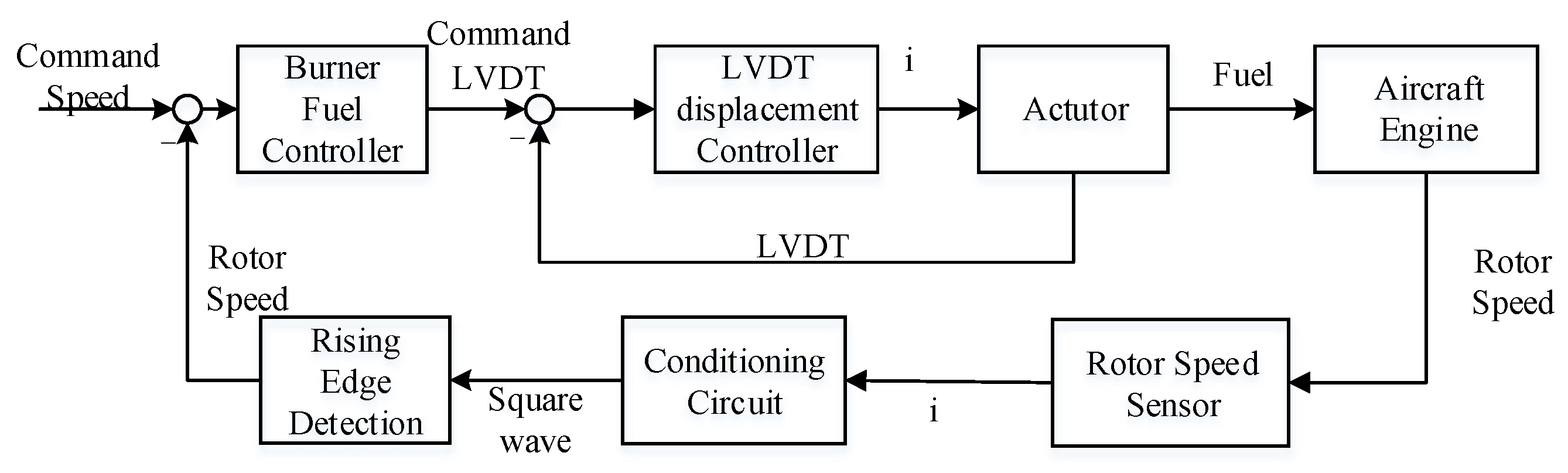
The rotor speed sensor converts the output speed value of the engine into the induction current of the corresponding frequency;
(2)
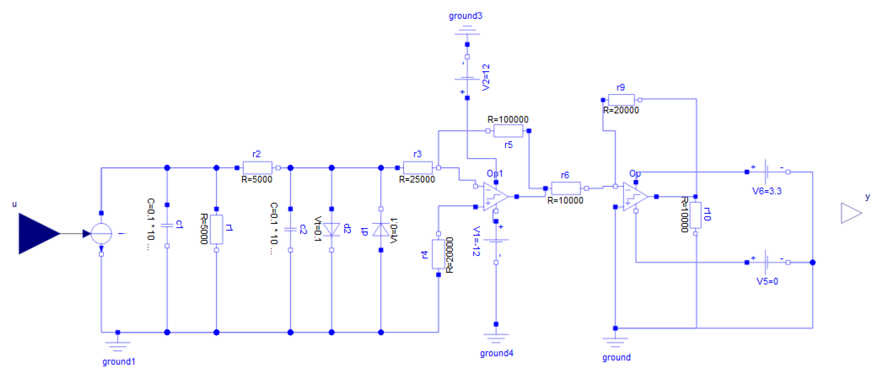
The conditioning circuit in EEC converts the current signal from the sensor into a square wave signal acceptable to the CPU;
(3)
The rising edge calculation module in EEC calculates the period of the square wave signal output from the conditioning circuit by the method of measuring the cycles and obtains the corresponding speed according to the relationship between the period of square wave signal and the speed. The control law in EEC calculates the output driving the current according to the reference speed, current speed, and displacement feedback of fuel actuator. The reference speed is converted from its relationship with the Power Level Angle (PLA);
(4)
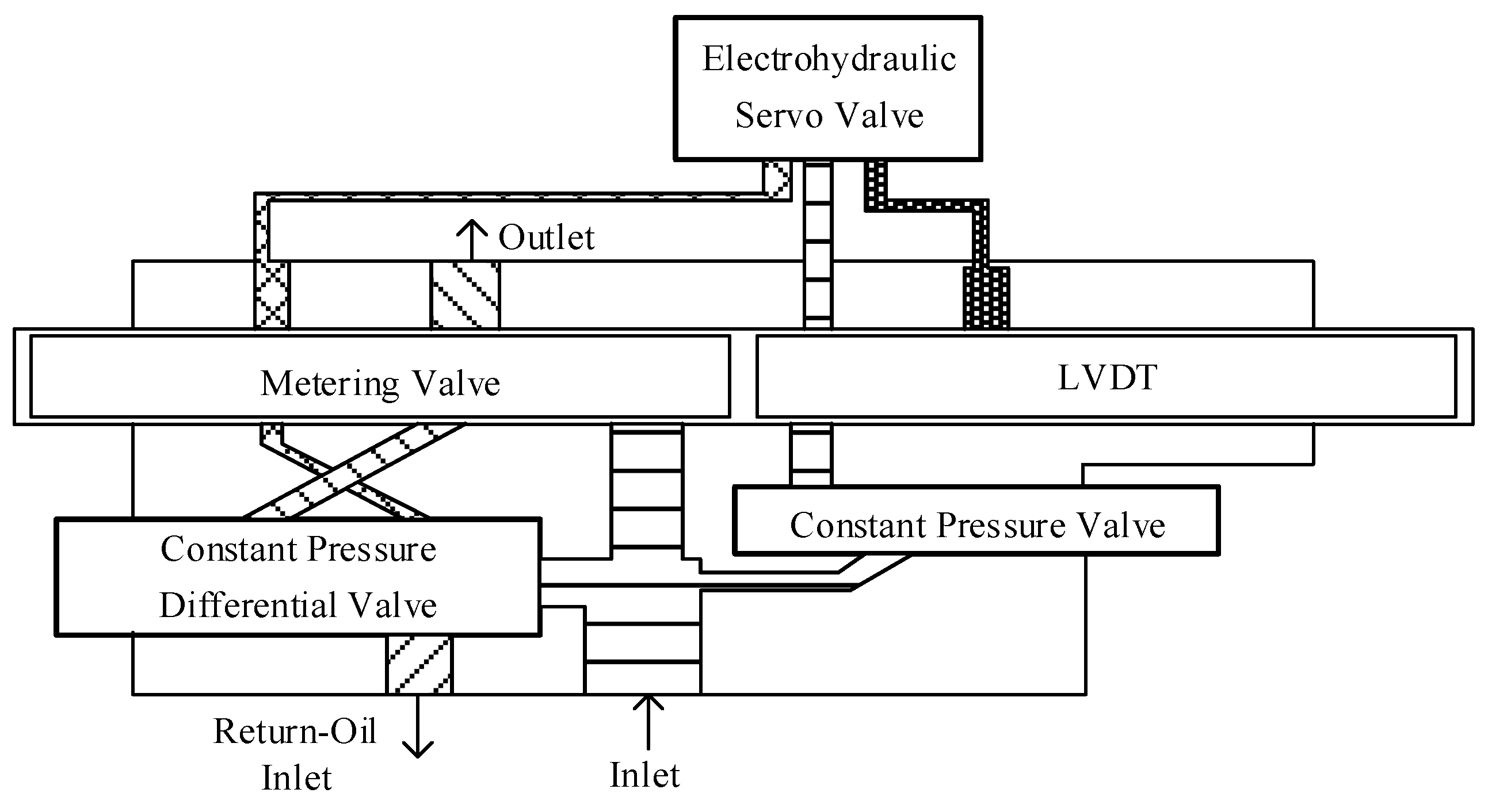
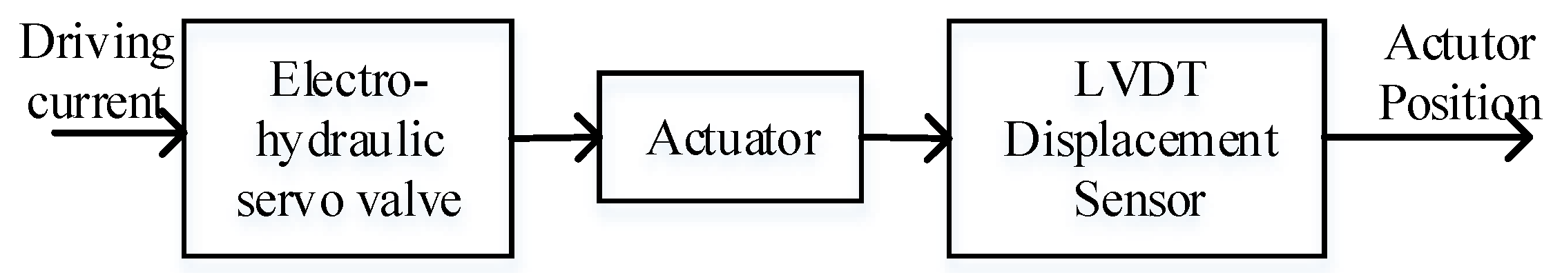
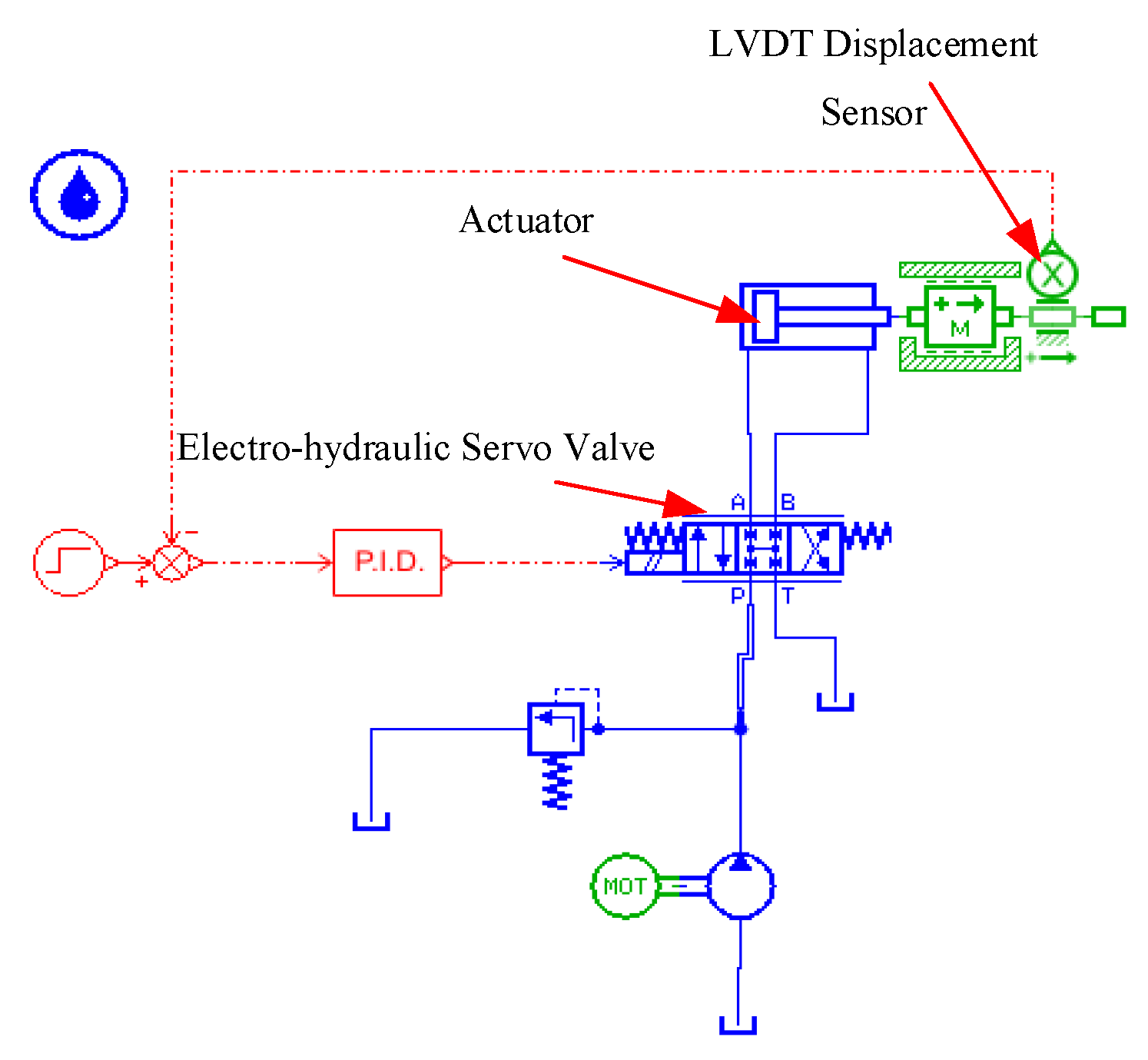
The electro-hydraulic servo valve in the fuel actuator receives the driving current, drives the actuator barrel to move and the output fuel to drive the engine to run. A Linear Variable Differential Transformer (LVDT) sensor measures the displacement of the actuator barrel and feeds it back to the control law;
(5)
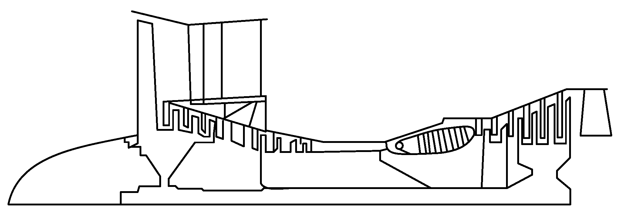
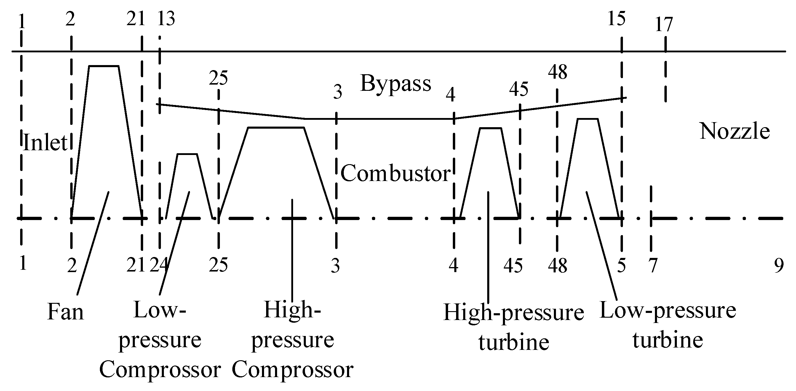
The engine module is a component-level model of JT9D. It receives the fuel output from the fuel actuator and outputs the rotor speed.
Because of the characteristics of each component and subsystem, different software is adopted to build the corresponding model, which mainly depends on whether the model library contained in the simulation software can cover the complex characteristics of the subject. This paper adopts Simulink to build the rotor speed sensor model, rising edge calculation module, and control law model, Modelica to build the rotor speed sensor conditioning circuit model, AMESim to build the fuel actuator model, C language and Simulink to build the engine model, and finally integrate these models and control law based on FMI to realize co-simulation.

2.1. Establishment of the Rotor Speed Senor Model Using Simulink

Simulink is the most widely used modeling tool based on functional module modeling language, which makes modeling easier and clearer. In addition, Simulink has a mature tool library of signal processing and mathematical computing models, which can be readily applied to the modeling of signal processing objects.
A magnetoelectric speed sensor is commonly used in aeroengines. It is mainly composed of a permanent magnet, ferromagnetic core, induction coil, and phonic wheel. Its structure is illustrated in Figure 3.
The phonic wheel is installed on the engine rotating axle and rotates with it. Each time the gear sweeps the magnetic field generated by the permanent magnet, the reluctance of the magnetic circuit will change. Then, the magnetic flux changes, generating inductive current in the coil and outputting the pulse signal.
A functional level model of the rotor speed sensor was built, and the function diagram is shown in Figure 4. The input of the model is the engine rotor speed, and the output is the inductive current generated by the sensor.
The induced current produced by the sensor can be approximated to a sinusoidal signal, and the relationship between the frequency and the speed can be expressed by Equation (1):
n = 60 f / z
where n (rpm) is the rotor speed, f (Hz) is the sinusoidal signal frequency, and z is the number of phonic wheel teeth. The induced current output by the sensor is:
e N = E m sin ( π n z t / 30 )
where E m (v) is the peak value of the induced current, and t refers to the current simulation time.
According to Equation (2), the model of rotor speed sensor is established. The Simulink model is shown in Figure 5. The input of the model is the rotor speed, and the output is the induced current. The number of phonic wheel teeth is 60 referring to a real sensor. It is necessary to note that the moment at which the input speed changes, the output signal will not change abruptly. To simulate this characteristic, time in Equation (2) was replaced by the integral of time.

2.2. Establishment of a Sensor Conditioning Circuit Model Using Modelica

Modelica is an object-oriented and non-causal modeling language. The object-oriented method ensures high reusability and conciseness of models. Non-causal modeling means that the mathematical language can be utilized to describe the behavior of the model without a relationship between the output and input of the model. These two characteristics make Modelica suitable for circuit modeling. Taking advantage of the characteristic of the visual interface, the model built in Modelica can maintain a high consistency with the circuit schematic.
The conditioning circuit model of the rotor speed sensor mainly includes a filter, clamp, amplification, and comparison module [22]. The circuit diagram is shown in Figure 6.
Load resistor R1 and load capacitor C1 convert the input current frequency signal into a voltage frequency signal. The low-pass filter composed of R2, R3, and C2 only allows a low-frequency signal to pass through. A clamp module composed of two reverse parallel diodes prevents excessive input signal from damaging the circuit. Amplifier LM358 and clamp modular can fix the amplitude of the signal within the acceptable range of EEC, and the delay comparison circuit composed of comparator LM393 prevents the disturbance of a signal waveform from affecting the measurement results.
Based on the integrated compiler environment Mworks [23], this paper builds the model of a rotor speed conditioning circuit. Because of the image drag modeling function of the software, the model can be built very quickly. The model is shown in Figure 7. It can be found that the model based on the visual interface is similar to the schematic diagram of the conditioning circuit in Figure 6.

2.3. Establishment of the Control Law Model Using Simulink

Simulink has an advanced tool library of linearization and control algorithms and is the most widely used tool in control law design.
In this paper, the control system built in Simulink is composed of fuel closed-loop control and LVDT displacement closed-loop control as Figure 8 shows. The main fuel closed-loop control, which is also called outer-loop control, includes the main fuel controller, engine, and rotor speed sensor, etc. According to the error of the command speed and actual rotor speed measured by the rotor speed sensor, the main fuel controller calculates the required LVDT value as the reference value of the LVDT displacement closed-loop control. The LVDT displacement controller then calculates the driving current that drives the actuator to release the fuel needed by the engine.
When designing the control law, the LVDT displacement closed-loop controller is first designed. Then, the fuel actuator and engine are regarded as a one non-linear system, and the system is linearized by the fitting method. Thus, a set of state-space models is obtained. For each state-space model, a PI controller is designed in the frequency domain. Finally, the gain of the PI controller is regulated according to the high-pressure rotor speed.
The model built in Simulink is shown in Figure 9.

2.4. Establishment of a Fuel Metering Device Model Using Amesim

Aiming at the modeling and simulation of a fuel metering device, AMESim, which has a diverse mechanical, hydraulic, pipeline, and pneumatic library, provides an efficiently way of rapid modeling and simulation of fuel metering devices.
A fuel metering device is mainly composed of an electro-hydraulic servo valve, constant pressure differential valve, constant pressure valve, actuator barrel (metering valve assembly), LVDT displacement sensor, and so on. Its structure diagram is shown in Figure 10. After receiving the current signal of EEC, the electro-hydraulic servo valve drives the cylinder to move; thus, the openness of the metering valve is changed. In this process, the constant pressure difference valve is required to keep the pressure difference of the metering valve unchanged to make sure that the fuel output only depends on the openness of the metering valve. The constant pressure valve assembly is adopted to ensure that the oil-source pressure of the servo valve remains unchanged.
A simplified and general fuel metering device model is built, which basically includes an electro-hydraulic servo valve, actuator, and LVDT displacement sensor. The overall structure is shown in Figure 11.
The electro-hydraulic servo valve receives the electric signal from EEC and controls the displacement of the actuator valve. The LVDT displacement sensor feeds back the actual displacement to EEC to form the closed-loop displacement control. By calibrating the relationship between the position of the actuator barrel and the amount of fuel, the demand fuel is exported to the engine.
The AMESim model of fuel metering is shown in Figure 12.

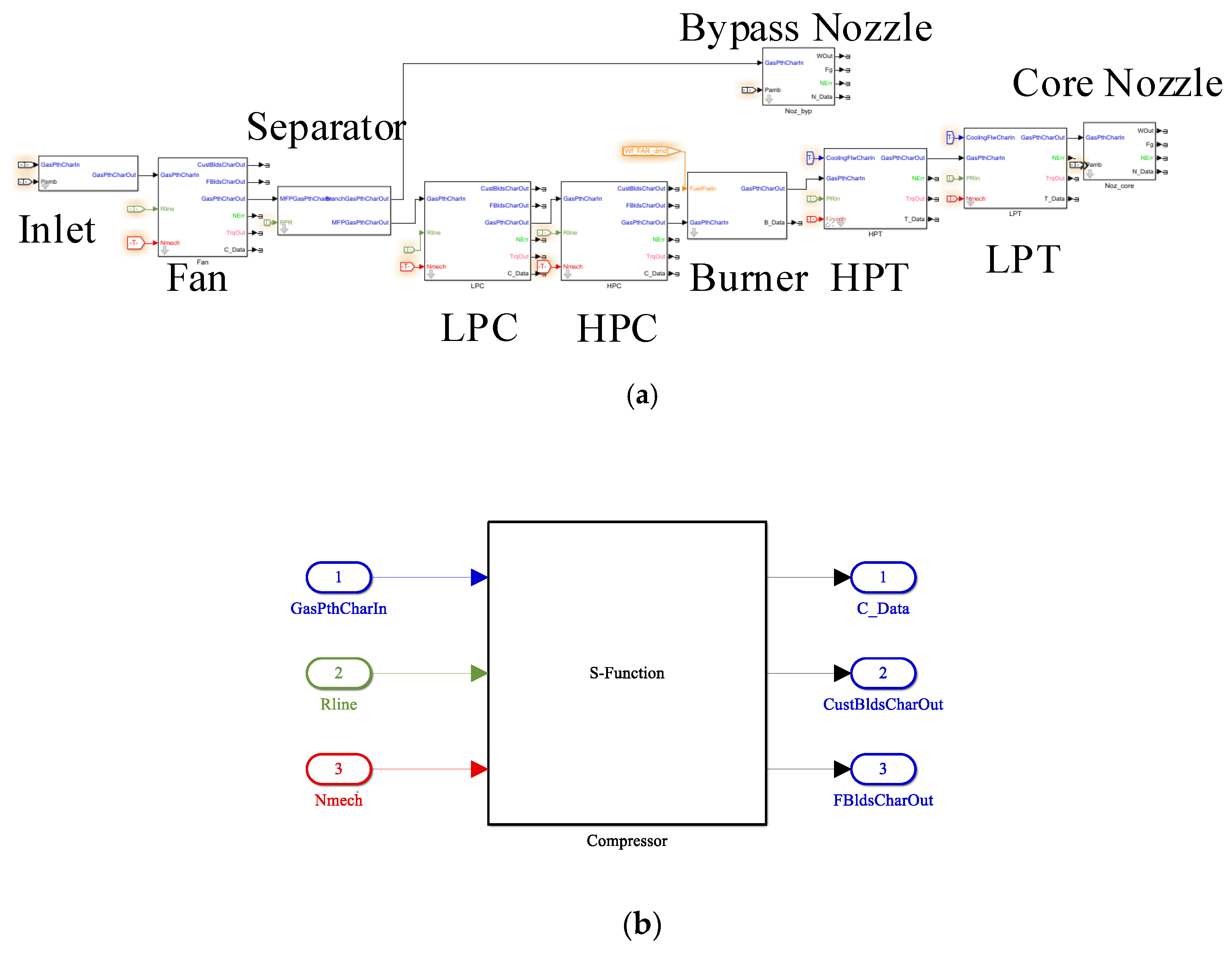
2.5. Establishment of an Engine Model Using Simulink and C Language

Aeroengine modeling is usually based on FORTRAN or C language due to the consideration of operational efficiency and technical legacy issues. TMATS (Toolbox for the Modeling and Analysis of Thermodynamic Systems) [24] is a simulation library for thermodynamic system modeling and control law developed by NASA in the United States. The core thermodynamic calculation part of the library is based on C language and is encapsulated into Simulink module with the S-Function. This method not only improves the reuse rate of the model with object-oriented characteristics, but also guarantees the operating efficiency of model.
The engine model in this paper is a component-level model of a JT9D turbofan engine [25] with a large bypass ratio designed and manufactured by P&W in the 1960s. Its structure is shown in Figure 13 [26]. It mainly consists of nine components: inlet, fan, low-pressure compressor, high-pressure compressor, burner, high-pressure turbine, low-pressure turbine, core nozzle, and bypass nozzle. Its physical working principle can be briefly described as follows: airflow enters the engine from the inlet, then passes through the compressor after isentropic compression, making the speed of air decrease and the pressure increase. In the next step, high pressure air flows to the burner and mixes with fuel to obtain combustible gas. After isobaric combustion, the internal energy of the gas converts to a large amount of thermal energy. When gas passes through the turbine, the thermal energy is converted into mechanical energy by isentropic expansion, which drives the turbine to rotate, and the turbine drives the compressor to rotate. The gas eventually expands further in the nozzle, converting the remaining thermal energy into kinetic energy and ejecting at high speed to provide the power needed by aircraft.
The structure of the JT9D component-level model in this paper is shown in Figure 14. Thermodynamic calculation of each component is carried out sequentially from the given inlet conditions, and then the parameters of each outlet section and the output of the engine can be obtained. At the same time, the interaction equations of each component should be met, which means the air mass flow of each engine section and the shaft power of rotors should be balanced when the engine is at steady state. When the engine is in a dynamic state, the shaft power of the rotors is no longer balanced, and the deviation of the power leads to the acceleration or deceleration of the rotor speed.
In this paper, the C/Simulink model of the JT9D engine is shown in Figure 15a. Figure 15b shows the structure of the compressor. The thermodynamic calculation of components is S-Function modular written in C language.

3. Full Digital Co-Simulation of the Control System in FMI

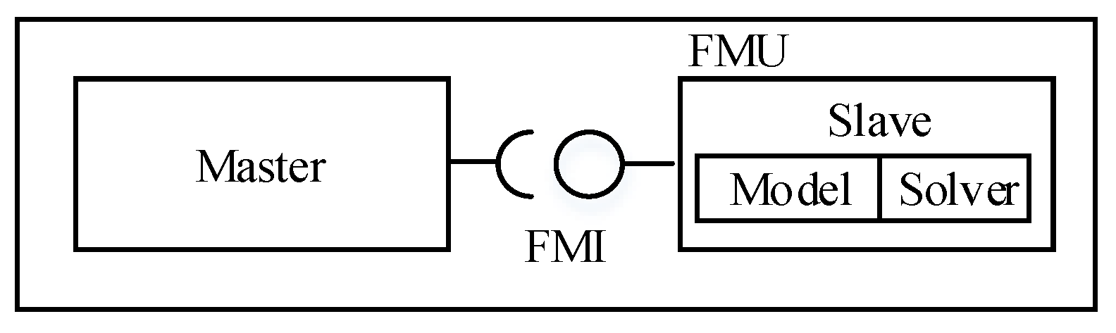
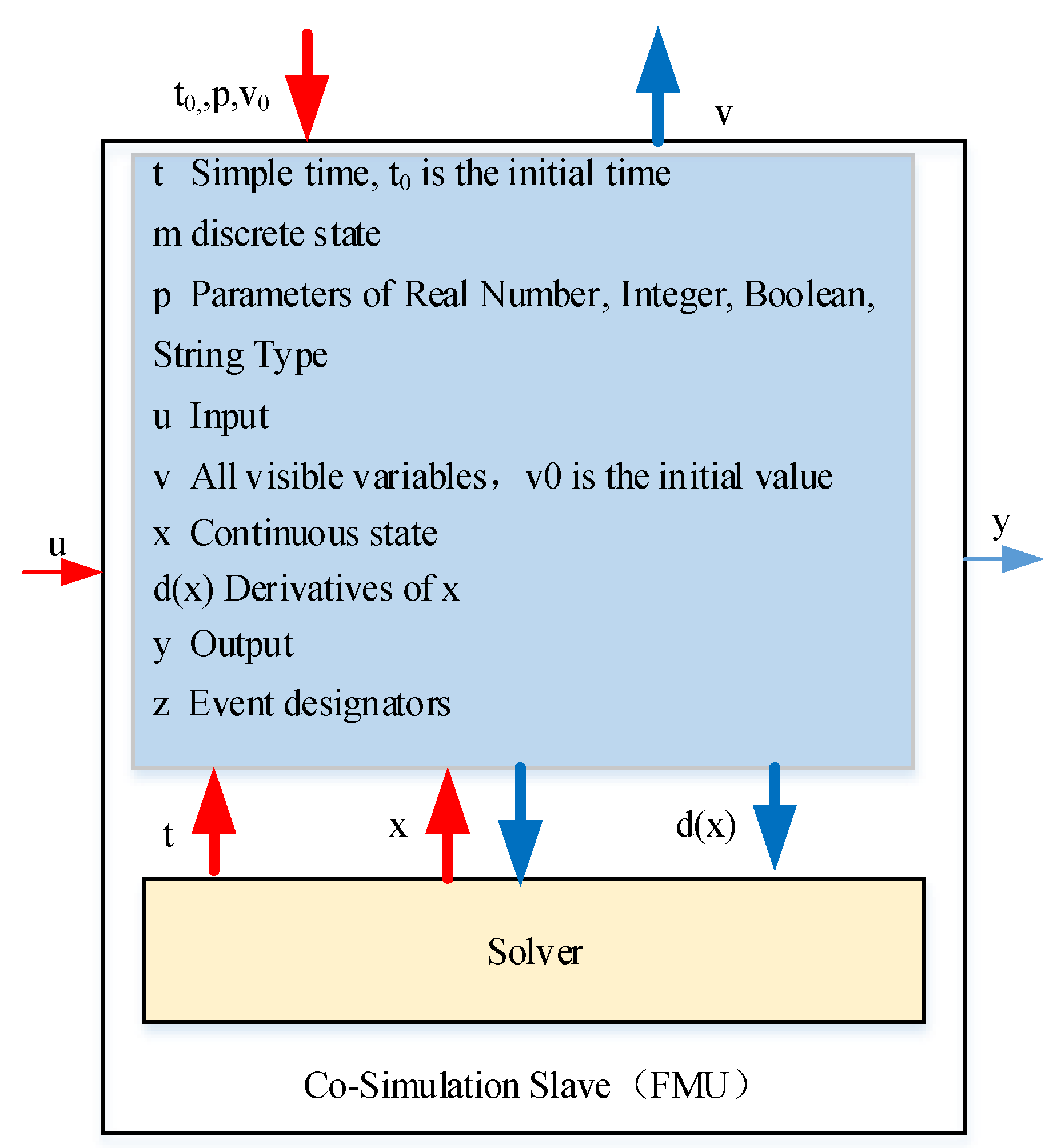
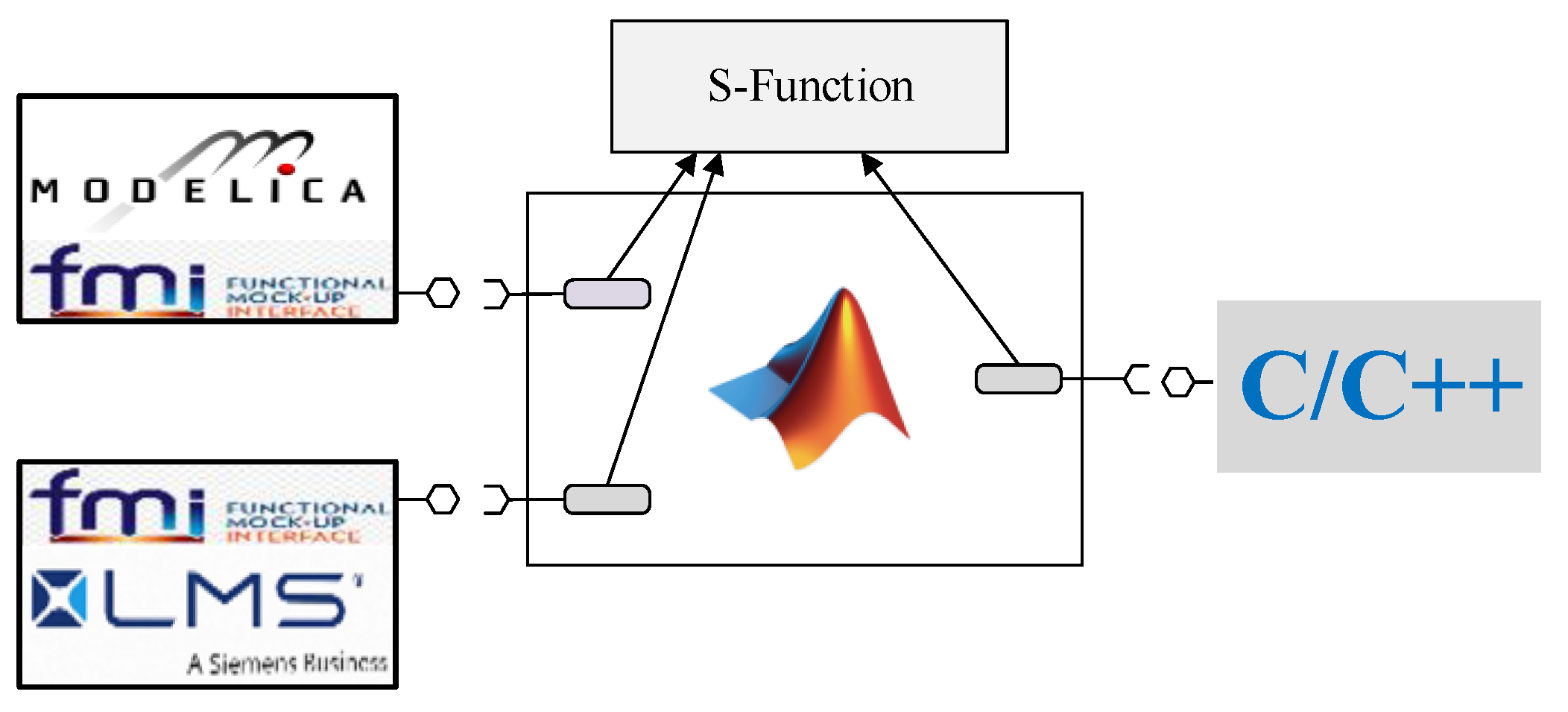
3.1. Introduction of FMI and Its Simulation Mechanism

FMI defines a general interface specification for co-simulation. Model components conforming to FMI specification are called FMU, which are usually converted by simulation tools supporting FMI specification. The specification defines two modes, one is Model Exchange (ME) and the other is Co-Simulation (CS). The difference between them is that FMU of the first mode does not contain a model solver, while the latter does.
The second mode was chosen. The simulation mechanism of this mode is shown in Figure 16. The master calls the slave program (FMU) through the interface provided by FMI specification. The master can be either a simulation platform supporting FMI or a C program. In this paper, Simulink is used as the main control program in the full digital simulation stage, and C program is used as the main control program on the HIL platform. FMU is a model derived from simulation tools supporting the FMI standard. It is called Slave in co-simulation and contains a model and solver needed by simulation. The exported files consist of two parts: model description file (xml), which contains all information of model export variables; dynamic link library file (dll), which is a file encapsulating all the functions needed by the model.
The simulation software involved in this paper transforms the model into a differential algebraic equation (DAE) or ordinary differential equation (ODE) and then solves them by the solver. The DAE equation can also be transformed into ODE Equation (3) [27]. In the process of exporting the model to FMU, the simulation tool encapsulates the solving process of the equation, so the FMU has the structure and variables shown in Figure 17.
y : = f o ( t , x c , x d , u ) x ˙ : = f d ( t , x c , x d , u ) x d : = f u ( t , x c , x d , u )

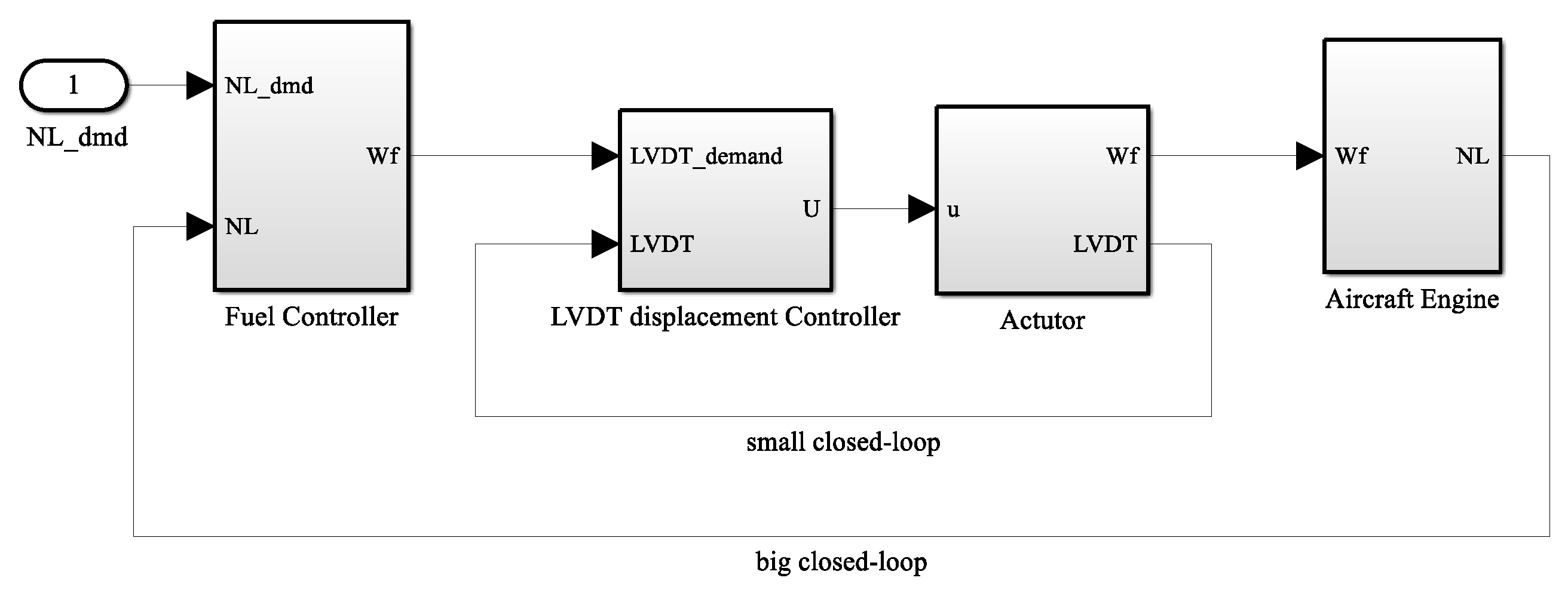
3.2. Full Digital Co-Simulation

In this section, Simulink is chosen as the main control program to carry out full digital co-simulation. Firstly, FMU is generated from the Modelica model and AMESim model and imported into Simulink. The connection between them is shown in Figure 18.
The overall Simulink model is shown in Figure 19, where the fuel actuator and rotor speed conditioning circuit are the imported FMU, and the rest of the models are built by Simulink and C (S-Function).
The simulation results are shown in Figure 20, Figure 21 and Figure 22. Figure 19 shows the result of the full digital simulation. The start and stop stages are under open-loop control, and the other stages are under closed-loop control. The actual speed is the feedback value of the engine model, and the measured speed is the speed calculated from the rising edge of EEC. The relative error between them is shown in Figure 20, with a maximum of no more than 0.4%. The source of the steady-state error is that there is an error of ± 1 counting the clock pulse when measuring the speed by the cycle measuring method. The relative error is E = ( 1 / m 0 ) × 100 % , and m 0 is the pulse number of the internal clock in a period of the measured rotor speed. In simulation, the period of the internal clock can be considered to be the simulation step size. If the simulation step size is set to 10 6 s and the rotor speed is 1000 rpm, then the relative error is 0.1%. The simulation results accord with the theoretical analysis. The error of the dynamic process is greater than the steady state at the initial stage, which is caused by the delay of pulse signals when measuring rotor speed by the cycle measuring method. Figure 22 shows the effect of LVDT displacement closed-loop control. It can be seen from the figure that the actual displacement of the actuator tracks the demand displacement exactly.

4. Integration and Verification on the HIL Simulation Platform

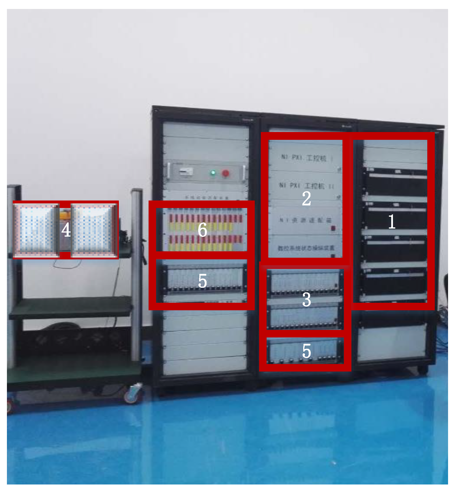
4.1. Introduction of the HIL Real-Time Simulation Test Platform

The HIL Real-time Simulation Platform (HIL Platform for short) is an aeroengine/gas turbine hard-ware-in-the-loop simulation platform, which can be used to verify digital models, control algorithms, fault diagnosis, and dual-channel switching algorithms. The HIL platform is shown in Figure 23.
The HIL platform is consist of six parts:
(1)
The first part is the IPC (Industrial Personal Computer), which mainly includes the data acquisition and monitoring system, main control platform, engine model real-time operation platform, and actuator model real-time operation platform. They are mainly used for monitoring data and running real-time models.
(2)
The second part is the data acquisition system, which is mainly responsible for collecting data from the IPC and controller.
(3)
The third part is the signal conditioning device, which receives data from the data acquisition system and simulates it as a real sensor signal.
(4)
The fourth part is the electronic controller, which receives the signals from sensors and calculates the control variables. The data acquisition samples every 5 milliseconds from the controller.
(5)
The fifth part is the load simulator, which receives the output of controller, and the data acquisition system collects its output and returns it to the IPC to complete the closed-loop simulation.
(6)
The sixth part is the system test adapter, which provides the function of fault injection.

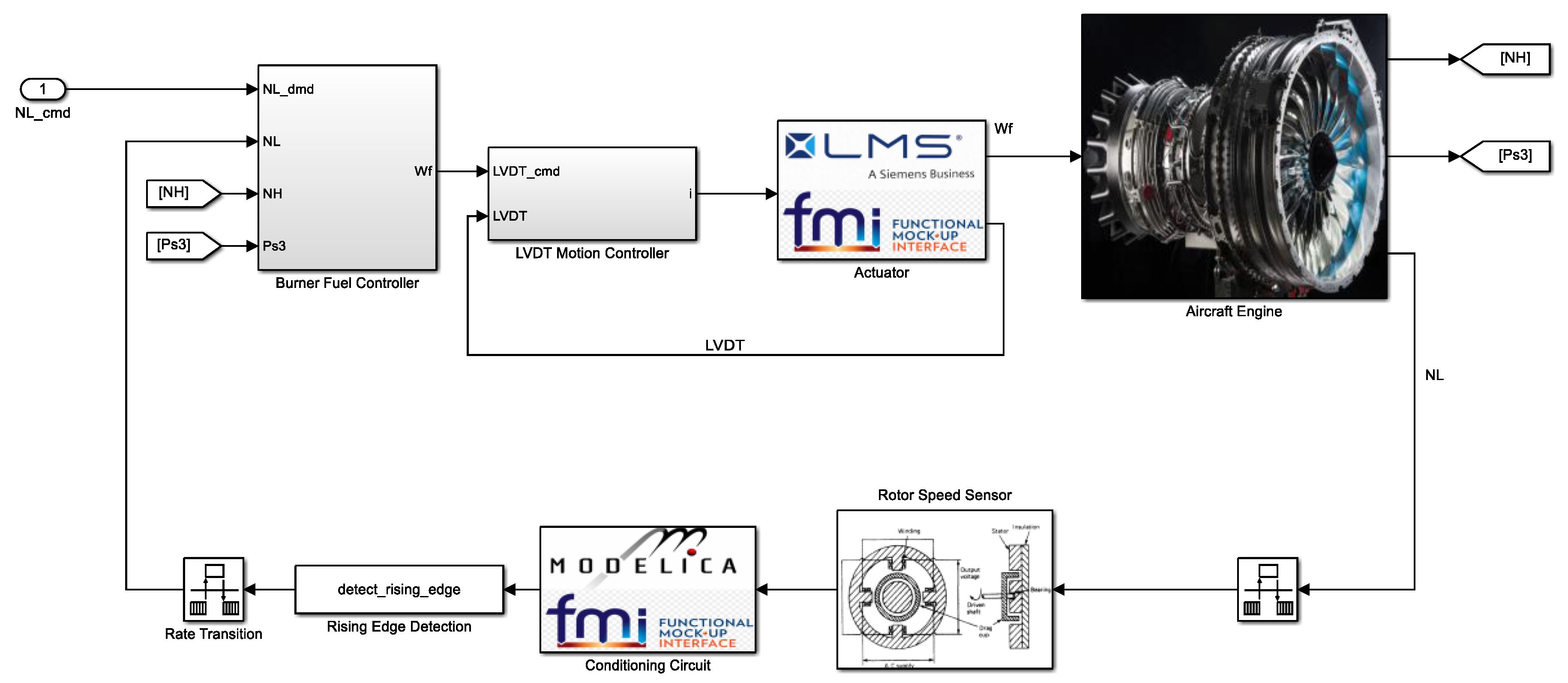
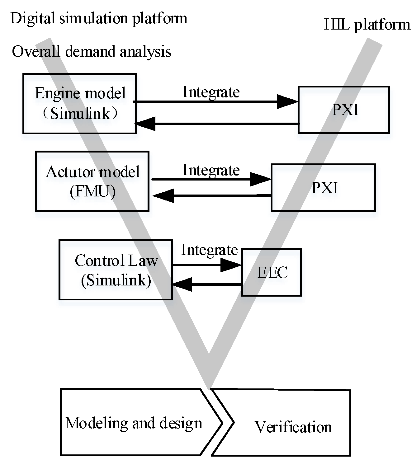
4.2. Overall Scheme of Integration of the Multidisciplinary Model and Control Law on the HIL Platform

The flow chart of analysis, design, integration, and validation of aeroengine control system is shown in Figure 24. Firstly, the requirement analysis of the whole control system is carried out and then the model and control law are designed in the full digital simulation platform. Finally, the model and control law are integrated and validated on the HIL platform. The Simulink/C hybrid model of engine and control law can be generated into C code by the Simulink code generation tool, and the C code can be encapsulated according to the interface specification of the HIL platform. Then, the engine model and control law are integrated into the engine model IPC and EEC, respectively. The focus of this paper is on the integration of the FMU model of the actuator in the IPC.
In order to integrate the actuator model FMU on the IPC of the HIL platform, it is necessary to encapsulate the master program that can call FMU into DLL according to the interface specification of the HIL platform, so that the IPC can call FMU. The schematic is shown in Figure 25.

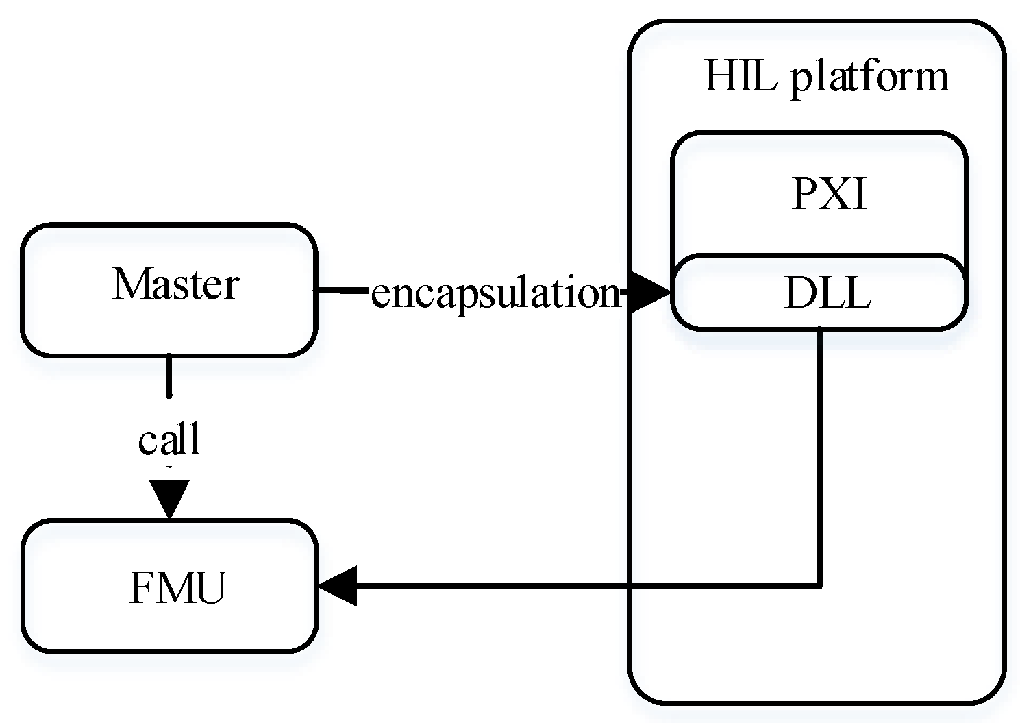
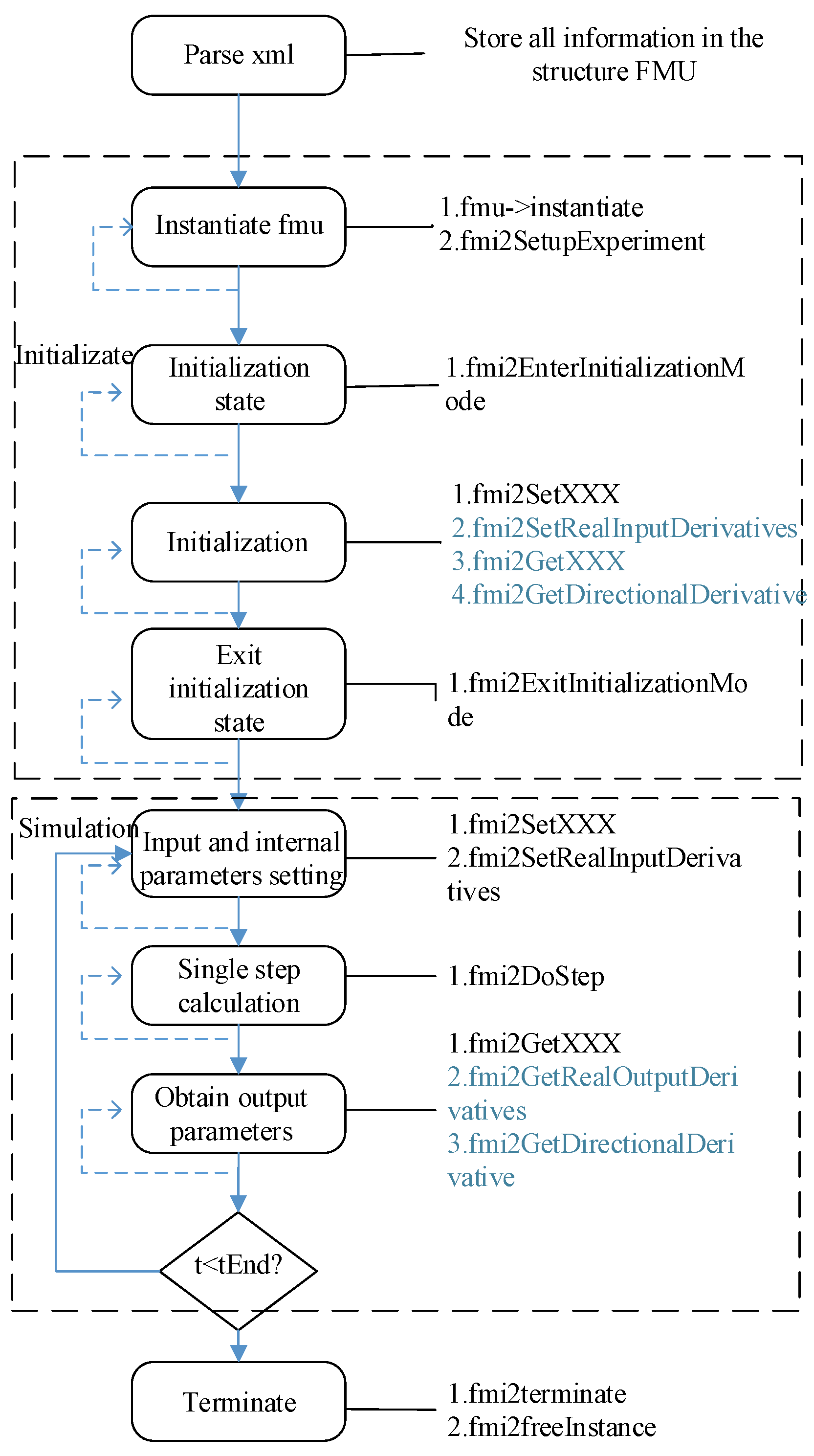
4.3. FMU Master Control Program

In order to realize the integration and verification of FMI on the HIL platform, it is necessary to write a master program according to the FMI specification to call the encapsulated functions in FMU. The main control program of FMU consists of three parts: the first part parses the XML file to get the internal information of the model, the second part initializes the FMU, and the third part is a single step simulation program. The main control program calls the functions of each part step-by-step according to the flow chart shown in Figure 26.
In the FMU simulation process, the function names and functions are shown in Table 1.

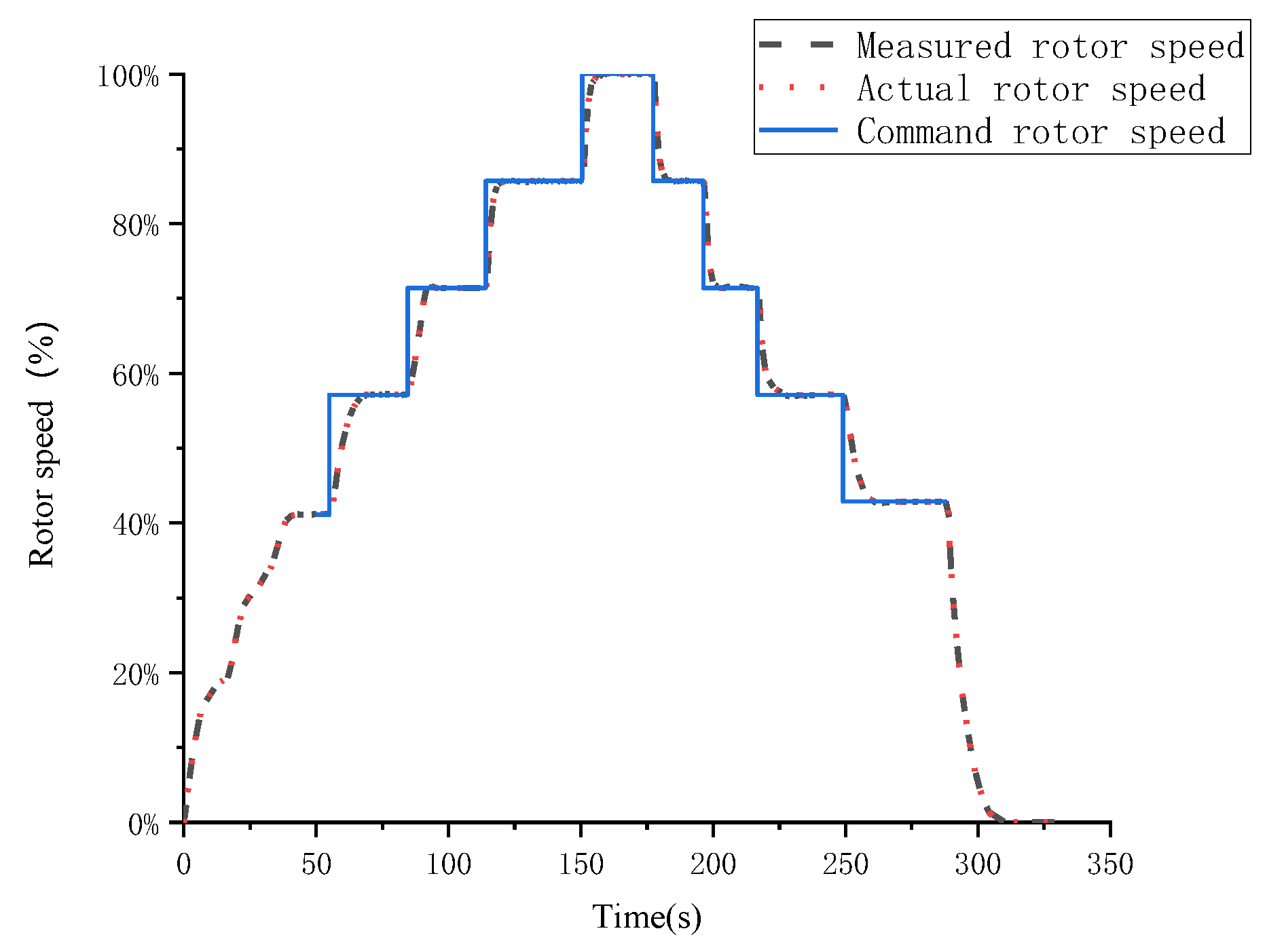
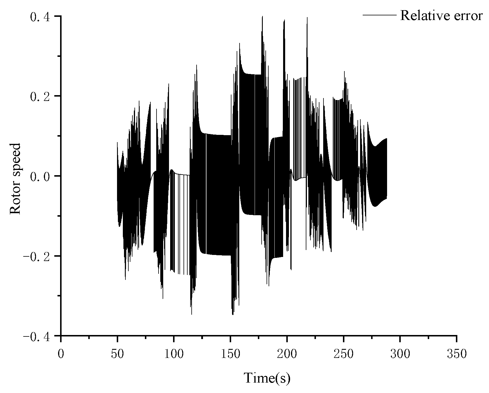
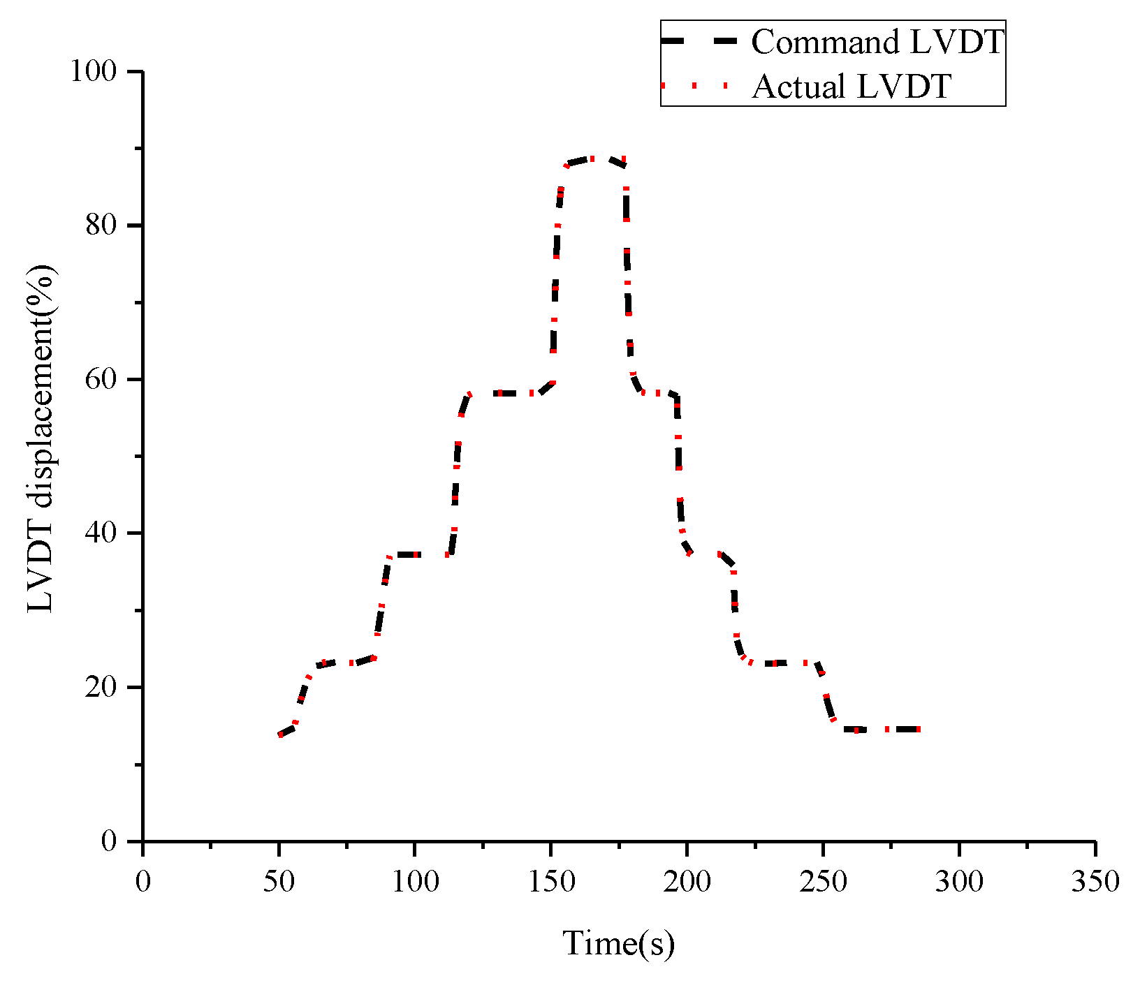
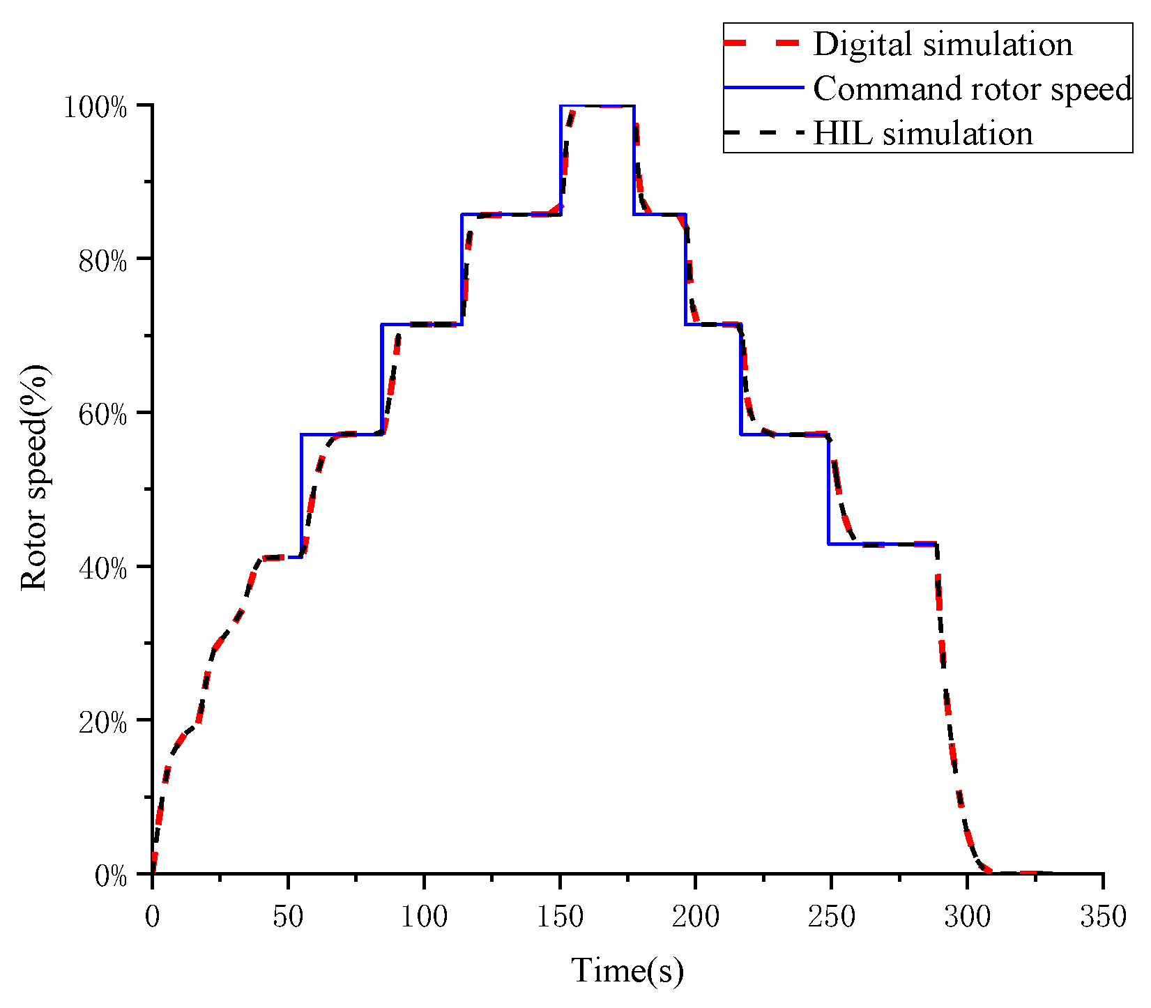
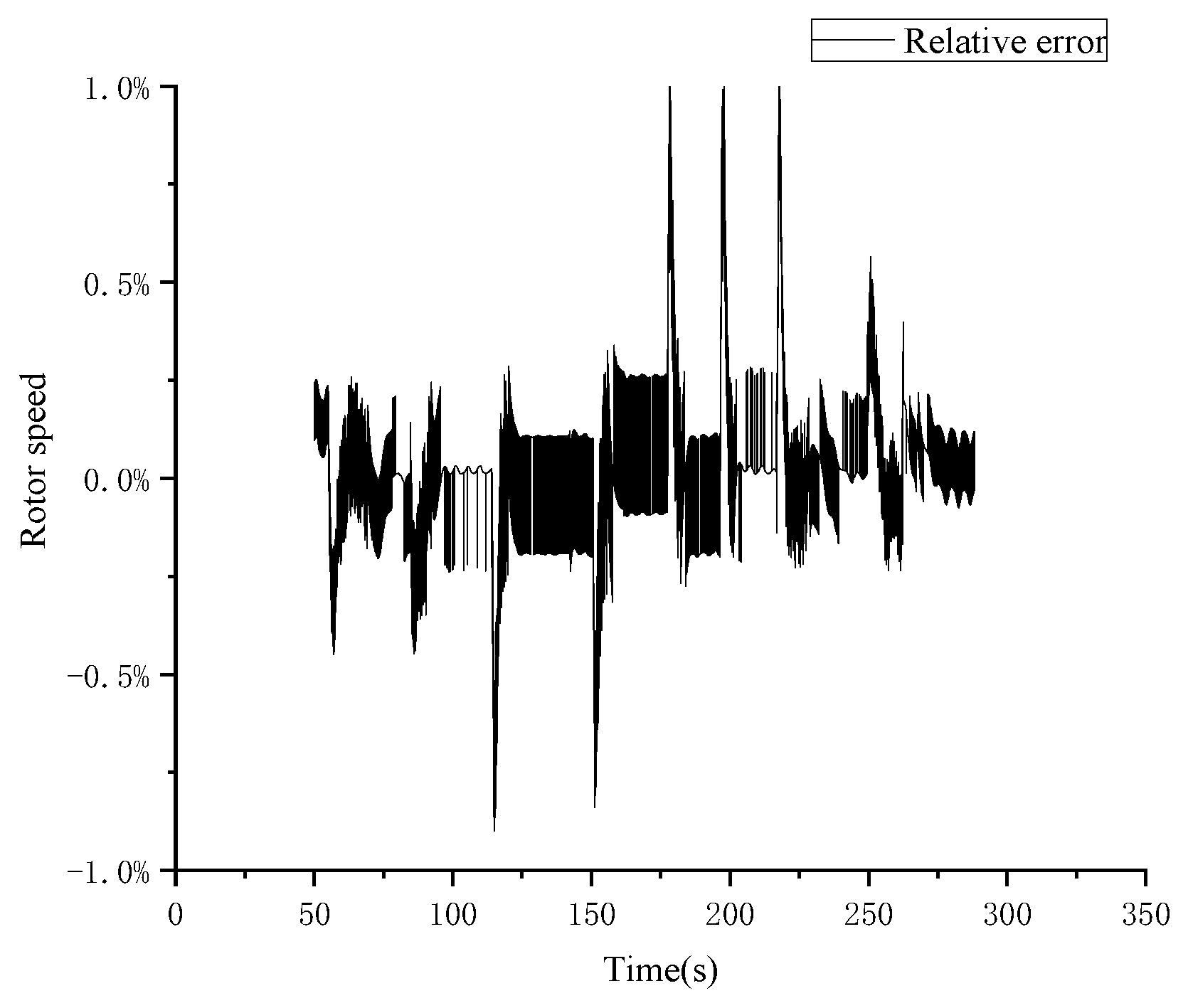
4.4. Simulation Result

The comparison of the HIL platform simulation result and full digital simulation result is shown in Figure 27. The relative error of the rotor speed in the closed-loop control stage of the two platforms is shown in Figure 28. The maximum relative error is less than 1%, and the steady-state error is less than 0.5%. It shows that the simulation results of full digital simulation and the HIL platform are almost identical, which shows that FMI can be integrated on the HIL platform successfully.

5. Conclusions

This paper presented a method for co-simulation between four different tools and platforms of aeroengine control system detailed models. To achieve this, the FMI technology was used and proven effective. In addition, the result of real-time simulation on the HIL platform shows the possibility of promoting the scalability of the HIL platform in this way. The FMI-based co-simulation in the paper provides a simple design method for aeroengine control system researchers and can be also used in many other fields, for example, dynamic simulation of aircraft, lightning resistance tests, etc. It works well in reducing the design period and improving the reusability of the model by making full use of different professional commercial tools. It is worth mentioning that the simulation on the HIL also indicates that there are some potential real-time issues. In other words, for more complex models, further research on model simplification and distributed parallel simulation is still needed to shorten the time of co-simulation.

Author Contributions

Conceptualization, J.W. and Z.H.; methodology, J.F. and M.L.; software, J.F. and M.L.; validation, J.F. and M.L.; formal analysis, J.F., M.L., J.W. and Z.H.; investigation, J.F. and M.L.; resources, J.F. and M.L.; data curation, J.F. and M.L.; writing—original draft preparation, J.F.; writing—review and editing, J.F., M.L. and Z.H.; visualization, J.W.; supervision, J.W. and Z.H.; project administration, J.W.; funding acquisition, J.W. All authors have read and agreed to the published version of the manuscript.

Funding

This study was supported in part by the Fundamental Research Funds for the Central Universities (no. NS2020017); in part by the Central Military Commission Foundation to Strengthen Program Technology Fund (no. 2019-JCJQ-JJ-347); in part by Major Special Basic Research Projects for Aviation Engines & Gas Turbines (no. 1002-DLJ19002); and in part by Major Special Basic Research Projects for Green & Sustainable Manufacturing (no. 1002-DCB16001).

Institution Review Board Statement

Not applicable.

Data Availability Statement

Data are contained within the article.

Acknowledgments

The authors gratefully acknowledge the financial support for this project from the Fundamental Research Funds for the Central Universities (no. NS2020017); in part from the Central Military Commission Foundation to Strengthen Program Technology Fund (no. 2019-JCJQ-JJ-347); in part from Major Special Basic Research Projects for Aviation Engines & Gas Turbines (no. 1002-DLJ19002); and in part from Major Special Basic Research Projects for Green & Sustainable Manufacturing (no. 1002-DCB16001).

Conflicts of Interest

The authors declare that they have no known competing financial interest or personal relationships that could have appeared to influence the work reported in this paper.

References

  1. Zhang, D.; Lu, J.Z.; Wang, L.; Li, J. Research of model-based aeroengine control system design structure and workflow. Procedia Eng. 2015, 99, 788–794. [Google Scholar] [CrossRef] [Green Version]
  2. Lu, J.Z.; Ding, J.W.; Zhou, F.L.; Xiong, G. Research of tool-coupling based electro-hydraulic system development method. In Proceedings of the 6th International Asia Conference on Industrial Engineering and Management Innovation, Tianjin, China, 25–26 June 2015; Atlantis Press: Paris, France, 2016; pp. 213–224. [Google Scholar]
  3. Lytle, J.; Follen, G.; Naiman, C.; Evans, A.; Veres, J.; Owen, K.; Lopez, I. Numerical Propulsion System Simulation (NPSS) 1999 Industry Review; NASA: Washington, DC, USA, 2000. [Google Scholar]
  4. Wang, Y.; Gu, G.Q. Summary of CORBA Technique. Comput. Sci. 1999, 26, 1–6. (In Chinese) [Google Scholar]
  5. Xu, Z.D.; Wang, J.Y.; Zheng, H. Summary of HLA and the key technologies in simulation applications. Comput. Simul. 2001, 18, 21–23. (In Chinese) [Google Scholar]
  6. Tian, H.F. Functional mock-up interface (FMI) standard. In Proceedings of the 2011 International Conference on Information, Services and Management Engineering (ISME 2011), Beijing, China, 26–28 December 2011. [Google Scholar]
  7. Yu, L.; Ye, Z.F. AMESim modeling of aero-engine fuel metering device. Mod. Mach. 2014, 5, 26–29. (In Chinese) [Google Scholar]
  8. Wu, Z. Design of Parameter of Electric Control Augmented-Fuel System of Aero-Engine; Nanjing University of Aeronautics and Astronautics: Nanjing, China, 2007. [Google Scholar]
  9. Li, H.; Zhang, H.; Li, Y.; Ma, Y. Research on Real Time Modeling of Aero-Engine Actuators; Control Engineering of China: Beijing, China, 2015; Volume 22, pp. 747–751. (In Chinese) [Google Scholar]
  10. Li, Y.; Zhu, B.; Zhang, W. Simulink Dynamic System Modeling and Simulation Foundation; Xi’an University of Electronic Science and Technology: Xi’an, China, 2004. [Google Scholar]
  11. Gu, H.Y.; Bao, Y.J.; Lin, Q.; Zhang, F. Electronic circuit simulation based on modelica. Res. Explor. Lab. 2010, 29, 263–266. (In Chinese) [Google Scholar]
  12. Wang, X.F.; Guo, Y.Q. Design and simulation of rotate speed sensor modulation circuit for aero-engine. Electron. Meas. Technol. 2007, 30, 150–152. (In Chinese) [Google Scholar]
  13. Cai, M.; Gras, H.; Mahseredjian, J.; Rutovic, E.; El-Akoum, A. Functional Mock-Up Interface-Based Approach for Parallel and Multistep Simulation of Electromagnetic Transients. IEEE Trans. Power Deliv. 2018, 33, 2978–2988. [Google Scholar] [CrossRef]
  14. Cech, M.; Konigsmarkova, J.; Reitinger, J.; Balda, P. Novel tools for model-based control system design based on FMI/FMU standard with application in energetics. In Proceedings of the 21st International Conference on Process Control, Strbske Pleso, Slovakia, 6–9 July 2017; IEEE: Piscataway, NJ, USA, 2017; pp. 416–421. [Google Scholar]
  15. She, Z.L.; Li, C.H.; Fu, J.F. Characteristics simulation of aero-engine fuel piston pump based on AMESim. Microprocessors 2014, 4, 83–90. (In Chinese) [Google Scholar]
  16. Gu, N.; Ni, J.M. Simulation of Engine cooling system based on AMESim. In Proceedings of the 2nd International Conference on Information and Computing Science, Manchester, UK, 21–22 May 2009; IEEE: Piscataway, NJ, USA, 2009; Volume 4, pp. 117–120. [Google Scholar]
  17. Ren, Z.B.; Meng, G.; Wang, Y.X.; Jay, F. Modeling and performance simulation for gas generator of aeroengine based on Modelica and Dymola. Gas Turbine Exp. Res. 2005, 32, 36–39. (In Chinese) [Google Scholar]
  18. Tavernini, D.; Vacca, F.; Metzler, M.; Savitski, D.; Ivanov, V.; Gruber, P.; Sorniotti, A. An explicit nonlinear model predictive ABS controller for electro-hydraulic braking systems. IEEE Trans. Ind. Electron. 2019, 67, 3990–4001. [Google Scholar] [CrossRef]
  19. Zhang, J.; Lv, X.; Lv, Y. Research on Vehicle Control Strategy and Hardware in Loop for Pure Electric FSAE Vehicle. J. Phys. 2021, 1732, 012172. [Google Scholar]
  20. Zhao, Y. Integrated Simulation Platform Based on Functional Mockup Interface and Its Application on Aerospace Engineering; Harbin Institute of Technology: Harbin, China, 2013. [Google Scholar]
  21. Yao, Y.C.; Zhou, W.H. Drivetrain model in loop simulation based on FMI standard. J. Mech. Electr. Eng. 2017, 34, 938–942. (In Chinese) [Google Scholar]
  22. Zhao, J.J.; Ding, J.W.; Zhou, F.L.; Chen, L. Modelica and its mechanism of multi-domain unified modeling and simulation. J. Syst. Simul. 2006, 18, 570–573. (In Chinese) [Google Scholar]
  23. Chen, X.; Wei, Z. A new modeling and simulation platform-Mworks for electrical machine based on modelica. In Proceedings of the 2008 International Conference on Electrical Machines and Systems, Wuhan, China, 17–20 October 2008. [Google Scholar]
  24. Chapman, J.W.; Lavelle, T.; May, R.D.; Litt, J.S.; Guo, T.H. Propulsion system simulation using the toolbox for the modeling and analysis of thermodynamic systems (T-MATS). In Proceedings of the AIAA/ASME/SAE/ASEE Joint Propulsion Conference, Cleveland, OH, USA, 28–30 July 2014. [Google Scholar]
  25. Hu, X.Y. World Small and Medium Aero Engine Manual; Aviation Industry Press: Beijing, China, 2006; pp. 443–445. [Google Scholar]
  26. Stakolich, E.G.; Stromberg, W.J. JT9D performance deterioration results from a simulated aerodynamic load test. J. Aircr. 1981, 20, 650–658. [Google Scholar] [CrossRef]
  27. Gomes, C.; Thule, C.; Broman, D.; Larsen, P.G.; Vangheluwe, H. Co-simulation: A survey. Acm Comput. Surv. 2018, 51, 49. [Google Scholar] [CrossRef]
  28. Wang, H.; Lian, D.; Xu, J. Research on distributed co-simulation based on FMI. Comput. Simul. 2017, 34, 256–261. (In Chinese) [Google Scholar]
Figure 1. Control system diagram for a typical turbofan engine.
Aerospace 08 00180 g001
Figure 2. Closed-loop speed control diagram.
Aerospace 08 00180 g002
Figure 3. Magnetoelectric speed sensor diagram.
Aerospace 08 00180 g003
Figure 4. Function diagram for the rotor speed sensor model.
Aerospace 08 00180 g004
Figure 5. Rotor speed sensor model in Simulink.
Aerospace 08 00180 g005
Figure 6. Rotor speed sensor conditioning circuit.
Aerospace 08 00180 g006
Figure 7. Rotor speed sensor conditioning circuit model in Modelica.
Aerospace 08 00180 g007
Figure 8. Aero-engine controller diagram.
Aerospace 08 00180 g008
Figure 9. Speed closed-loop control model in Simulink.
Aerospace 08 00180 g009
Figure 10. Fuel metering diagram.
Aerospace 08 00180 g010
Figure 11. Fuel metering model diagram.
Aerospace 08 00180 g011
Figure 12. Fuel Metering Model in AMESim.
Aerospace 08 00180 g012
Figure 13. JT9D engine diagram.
Aerospace 08 00180 g013
Figure 14. JT9D engine model diagram.
Aerospace 08 00180 g014
Figure 15. (a) JT9D engine model using C/Simulink. (b) JT9D compressor model using C/Simulink.
Aerospace 08 00180 g015
Figure 16. FMI CS mode simulation mechanism.
Aerospace 08 00180 g016
Figure 17. FMU structure and variables [28].
Aerospace 08 00180 g017
Figure 18. The connections between different tools.
Aerospace 08 00180 g018
Figure 19. Full-Digital co-simulation (Simulink Master).
Aerospace 08 00180 g019
Figure 20. Full-digital simulation of rotor speed control.
Aerospace 08 00180 g020
Figure 21. Relative error between the actual rotor speed and measured rotor speed.
Aerospace 08 00180 g021
Figure 22. Full-digital simulation LVDT displacement closed loop control.
Aerospace 08 00180 g022
Figure 23. HIL platform.
Aerospace 08 00180 g023
Figure 24. Model and control logic design, analysis, integration and testing process.
Aerospace 08 00180 g024
Figure 25. Schematic Diagram of FMU Integrated on HIL.
Aerospace 08 00180 g025
Figure 26. FMU simulation process.
Aerospace 08 00180 g026
Figure 27. Rotor speed control comparison between HIL and digital simulation.
Aerospace 08 00180 g027
Figure 28. Relative rotor speed error between HIL and the digital simulation.
Aerospace 08 00180 g028
Table 1. FMI function name and effect.
ProcessNameFunction
Instantiationfmi2SetupExperimentInitialize time and parameters
Initializationfmi2EnterInitializationModeJump into initialization
fmi2ExitInitializationModeExit initialization
Single step calculationfmi2SetXXXInput parameters
fmi2DoStepOne-step simulation
fmi2GetXXXOutput parameters
Terminationfmi2TerminatedStop simulation
fmi2FreeInstanceRelease examples
Publisher’s Note: MDPI stays neutral with regard to jurisdictional claims in published maps and institutional affiliations.

