1. Introduction
Software-defined radio (SDR) is a flexible technology that enables the design of an adaptive communications system. Accordingly, a generic hardware design can be used to address various communication needs, with varying frequencies, modulation schemes and data rates [
1]. The radio implementation process includes setting the filtering parameters, such as the pass and stop band frequencies, as well as digital quadrature transformations and data rate adjustments using up and down sampling processes.
Recent improvements in analogue to digital converter technology have led to the development of software-defined radios with digital receivers [
2].
Many satellites have adopted the SDR architecture as an experimental or secondary subsystem, but this year—according to the ESA—the first fully SDR commercial satellite was launched: the Eutelsat satellite “Quantum”. Eutelsat Quantum will be the first generation of universal satellites able to serve any region of the world and adjust to new business without the need to procure and launch an entirely new satellite. The first Quantum satellite will have a launch mass of 3500 kg, a power of 5 kW, and an all-Ku-band communications payload mass of 450 kg [
3]. Amateur operators have built many SDR-based ground stations; however, it is not yet common for amateur or educational small satellites to use SDR as the main communication subsystem. However, this will change in the near future, given the amount of research being carried out in this field and the benefits of SDRs over traditional radios, such as reconfigurability and adaptability.
Adaptation is one of the smartest use of the SDR. The European Space Agency (ESA) is currently funding the Satellite Adaptive Communication Channel project (SACC), a pioneer system intended to increase the data sent from satellites. Similarly, this paper develops a design to be implemented in Raspberry Pi devices, which are used as satellite subsystem processors. The design takes advantage of the SDR to reduce the cost and simplify the complexity of the electronics design; moreover, it boosts the communication system’s performance by implementing feedback and adaptable techniques.
In satellite communication, the Earth–satellite link is established only when the Earth station enters the beam width of the satellite’s antenna [
4].
As shown in
Figure 1, the slant range is the distance between the satellite and its ground station. Satellites arise to each specific ground station at the furthest point, then move closer until reaching a minimum distance at 90° elevation. Signal attenuation is highly dependent on the length of the line-of-sight path. As such, the maximum slant range value should be considered when designing the link budget. The designing of any communication system starts with the link budget analysis [
5]. The link budgets of satellites are designed to maintain connectivity in the worst case of communication. However, to utilize the communication windows, the signal’s characteristics may be altered in order to deliver more data to the ground station within the same period of time [
6]. When the satellite approaches the ground station’s horizon, the signal must travel a significantly greater distance than when the satellite is at the zenith of its path over the ground station. The graph in
Figure 2 shows the typical communication window line of sight range in kilometers for different altitude orbits.
Small spacecraft (SmallSats or small satellites) include spacecraft with a mass less than 180 kg [
7]. CubeSats fall under the definition of small satellites. The standards dictate that they weigh 1.33 kg maximum and are 1 cm × 1 cm × 1 cm.
The distance between a satellite in ISS orbit and its ground station can reach more than three times the distance when the satellite is at zenith. This directly affects the received signal strength at the ground station.
The second column of
Table 1 shows the differences in distance between the edge points of the communication window, i.e., 5° and 90° elevation angles, for several low Earth orbits (LEO). The third column shows the power density loss between the same edge points excluding atmospheric attenuation. This value describes the variation in power in that specific orbit. Since we excluded the atmospheric loss, the power loss difference is equal to the difference in free space loss (FSL) between the edge points of the pass calculated by Equation (1) [
8].
where
d: slant range;
signal Wavelength.
The main goal of the research is to dynamically change the data rate of the transmission so that it can exploit the change in the channel. This would increase the quantity of data that can be delivered within the short communication period available for satellites in low Earth orbit (LEO). This allows us to automatically tweak the transmitted signal characteristics and the transceivers’ parameters, allowing the system to perform better in dynamic channels.
Table 1 explains that satellites in lower orbit would benefit more from this adaptability than satellites in higher orbits. The distance the signal must travel to a nadir ground station is 10 times greater than the distance the signal must travel when that satellite is at the acquisition of signal (AOS) point in a 1000 km altitude orbit. The distance is 20 times greater in a 400 km altitude orbit.
Traditionally, SDRs are used to reduce the cost and the time required to develop communication systems [
9]. This paper and similar recent studies focus on improving their performance. This paper’s is significant because it is at the last step before implementing artificial intelligence (AI) in satellite communication systems. Adaptable systems allow users to adjust a satellite’s amplifier along the pass to ensure compliance with regulations, such as power density limits, while delivering adequate power to the ground station. Adaptable systems allow satellites to maximally benefit from their potential by tuning the link budget factors in relation to the current transmission situation in order to deliver the maximum quantity of data to the user.
As such, the novelty of the research paper is that the design optimizes the SDR system’s performance for small satellites, and it uses tools accessible to most satellite developers. Most importantly, it intends to make the use of an adaptable system in CubeSats and small satellites a reality, given that such adaptable systems are not used in CubeSats yet.
For a given received power, if we increase the rate of data transmission, the energy bit per noise density decreases. The designed adaptable system facilitates a higher rate of data delivery without increasing the transmission power when the received power increases due to smaller losses of signal. In this way, the required SNR at the receiver is maintained within the acceptable range. The relationship is shown by the following equations [
10].
where
Theoretically, whenever the SNR increases by 3 dB, we can transmit at double the data rate.
Table 2 compares three different approaches to designing a communication subsystem for small satellites. The traditional system is hardware-based, meaning that developers need to change hardware components in order to change the satellite’s characteristics. This paper designs a Raspberry Pi + SDR system.
In comparison with the traditional hardware-based systems, this design is more effective in using the available communication channel, and it has the ability to deliver more data. That said, the traditional systems are more robust. With specific improvements, this design could be made more reliable.
Some SDR-based systems use field-programmable gate arrays (FPGAs) to produce and modulate the signals of SDRs; this design is instead built to be implemented in Raspberry Pi devices, which are easier to program for students and academic researchers. Moreover, Raspberry Pi devices require less power and space, making them preferable for CubeSats and small satellites.
2. Methodology
The main design tasks are implemented using GNU Radio software, while the signal modulation and packet framing are carried out within GNU Radio’s blocks. Data inputs and outputs are handled by the user datagram protocol (UTP) and transmission control protocol (TCP) network protocols.
The design is implemented using a core-i7 laptop running an Ubuntu 18.04 LTS operating system. The tests discussed in detail in the “Tests and Results” section are run on the same core-i7 laptop to confirm its functionality and to measure its parameters. These parameters are obtained by repeating the test several times and calculating the mean value.
Scripting is performed using the Python language. Bash script and Python are used for testing.
This design could have been affected by the available hardware. If the design is to be implemented in another machine, it might need some adjustments. The version of the GNU Radio that is used is another important factor. When using a different version, the basic blocks and their dependencies might need to be updated.
The next stage of this design is to use it in a Raspberry Pi device as a satellite subsystem.
3. Design and Implementation
This section addresses general design aspects and gives details of the software implemented in the system, including the blocks of the GNU Radio flowgraphs.
3.1. Design Aspects
Feedback from the ground station transceiver is an essential part of this design, and thus both sides of the communication link are designed. However, the satellite transceiver is designed to support interoperability and compatibility with traditional systems. Feedback is achieved by exchanging signaling messages between the two ends of the system.
The spaceborne transceiver can generate three types of signals to send AX.25 packets: 2400 bps GMSK, 4800 bps GMSK and 9600 bps GMSK. It sends data in patches of packets. For LEO, the average time to pass over a given ground station is 10 min [
11], and so the length of the packet is chosen so as not to exceed 10% of this value. Between patches of data, a signaling message is sent containing three packets of data, each at a different rate. While sending, the satellite is also listening in order to capture feedback. According to the feedback, the rate of downlink signal data transmission is selected. On the other hand, the ground station transceiver replies to the signaling message with its feedback, stating the fastest reliable transmission mode.
The AX.25 protocol is selected to ensure that the system will work smoothly with traditional versions of the communication subsystems.
3.2. Software Development
The software code of the system requires multithreading features, as well as the ability to run in System on Chip (SoC) devices, in order to be integrated into the satellite bus. Therefore, the Ubuntu environment is chosen to run the system, and this allows it to be implemented in Raspberry Pi devices and thus in satellites.
Raspberry Pi devices have a history in space, and they are currently being used in several small satellite missions. They comply with satellite system standards.
To develop our system, GNU Radio Companion and Python 2 were used. GNU Radio is a free and open-source software development toolkit that provides signal processing blocks to implement software radios [
12].
The proposed process of software implementation involves generating a basic code in GNU Radio. This basic code is then modified and linked with other segments of the system, which are also Python programs. The main tasks of the code are to transmit and receive the data and signaling packets, and then, according to available information, the system parameters are altered for the next transmission session. In each session, data are transmitted in patches of packets.
The sequence of the tasks is shown in
Figure 3; the flow repeats itself every session.
The satellite transceiver starts the transmission with the most robust but slowest mode, 2400 bps GMSK. Following this, the data transceiver sends three small patches of packets for signaling. Each operates in a different mode. The ground station transceiver saves the data and signal in local files, and replies by feedback. The satellite sides save the feedback in a local file, and adjust the rate of data transmission for the next patch of data.
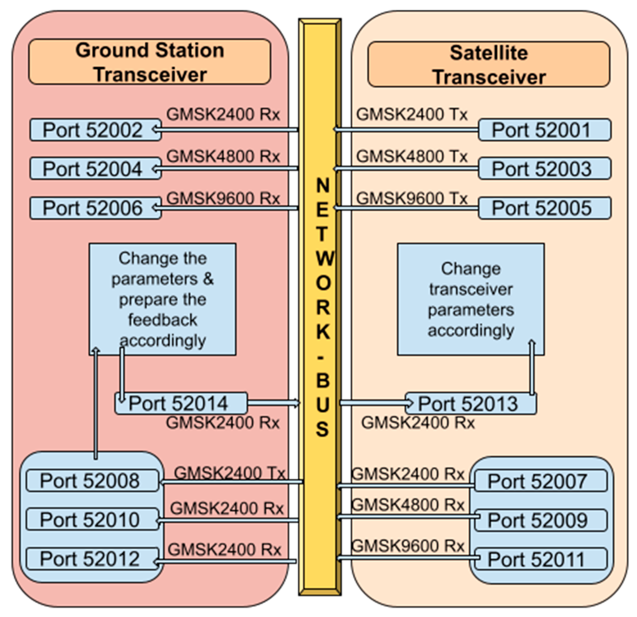
The system is highly dependent on the network transport layer’s protocols in exchanging the data. It uses different ports to detect and forward data and signal packets.
Figure 4 illustrates how the packets are exchanged between the ports.
As in
Figure 4, seven ports are required in each transceiver. Each one has a dedicated task and data rate. To ensure that no port attempts to transmit while another is transmitting, the threads are organized in the code following the timeline shown in
Figure 5.
In parallel with this sequence, another part of the code listens for feedback from the receiver. Such concurrency is achievable because of the multithreading support capability of Python. Feedback is sent by the ground station each time it receives a signaling message. The feedback is always in the 2400 bps GMSK mode.
To ensure that the system will not enter an infinite loop if some packets of the patch are not transmitted/received as expected, timeout timers at the transmitting and receiving parts of the code are introduced. In the case of data packet loss, the system stops waiting for the remaining packet, and while it correctly saves the received ones, it will not automatically request the missing packets to be resent. With respect to future improvements, it may be necessary to make is so that the receiver can request the retransmission of specific packets.
3.3. GNU Radio Flowgraphs
In addition to the original GNU Radio blocks, other blocks from different Out of Tree (OOT) modules are used to implement the flowgraphs. The following OOTs are used in the design and testing: gr-APRS, gr-ax.25, gr-bruninga, gr-limesdr, gr-osmosdr, gr-satellite, and gr-satnogs. Another simple OOT has been created to perform comparison tasks. Additionally, we have attempted to control the noise and the flowchart parameters during runtime using the XML-RPC protocol.
3.4. Data Input and Output
Data are fed into the system using the UDP Message Source block shown in
Figure 6. A separate Python script is written to feed this port with a 245-byte string of data. This string is forwarded as the input to the following block.
The output data is directed to TCP network ports, and the Socket PDU block of GNU Radio shown in
Figure 7 is used for this task.
3.5. Transceiver Design
3.5.1. GMSK Transmitter
The transmitter design is implemented as shown in
Figure 8. The input message is sent to an AX.25 encoder that generates bitstreams. Then, it is packed into data bytes (8 bits) to make it appropriate input for the “GMSK Mod” block, which will perform the modulation to GMSK. Then, the modulated baseband signal is passed through a rational resampler to generate the desired data rate. Then, the signal is ready, and it will be saved in a virtual sink.
3.5.2. GMSK Receiver
When the receiver receives the signal, it resamples it before passing it on to the low pass filter, and then on to demodulation, which is performed by the block “GMSK Demod”. Its output is a bit stream (
Figure 9).
The AX.25 frame bits are encoded such that the ones represent a change in the actual data bit value, while the zeros denote that the data bit value is the same as the previous bit. Therefore, to derive the original data bits, it is necessary to use a Non-Return-to-Zero-Inverted (NRZI) decoder block. Subsequently, a descrambler is used same as shift registers in the hardware-based radio for the synchronization and clock recovery.
In AX.25, the functions of high-level data link control (HDLC) are used. Thus, the “HDLC Deframer” block must discard corrupted frames via the frame check sequence (FCS).
Finally, the resulting bit stream is framed in AX.25 by the “HDLC to AX.25” block before sending it to the dedicated TCP port.
3.5.3. GMSK Data Rate Selection
The resampler’s properties are responsible for the generated data rate together with the system sampling rate and the number of samples per symbol. Its interpolation and decimation factors control the generated data rate.
In our design, a sample rate of 500,000 samples/second and 10 samples per symbol for the GMSK modulation are used. The transmitter’s resampler parameters are set to a decimation factor of 24 and an interpolation factor of 125, while the receiver’s resampler parameters are set to a decimation (“D”) factor of 125 and an interpolation (“P”) factor of 24 in order to generate a 9600-bps signal.
Equation (5) shows the relationship between these factors:
where
3.5.4. Noise Simulation
White noise is simulated by adding the signal generated by a “Noise Source” block to the original signal before sending it to the receiver. The value of the noise voltage is calculated using Equation (6) [
13].
where
: noise voltage
: number of bits per symbol
: signal-to-noise ratio in dB
The signal-to-noise ratio (SNR) is changed to control the value of the noise voltage while observing the reception of the signal in the other terminal.
Figure 10 shows the GNU Radio blocks used to simulate the channel noise.
3.5.5. Simulation Code
In the simulation, the transmitted data are fixed at a size of 245 bytes. The received packets are counted by the receiver while being written in the dedicated file.
3.6. Code Structure
The system code is composed of four executable Python files and three text files, which are used to save the received packets.
This Python file contains the main functions that execute the GMSK transmitter and receiver codes. It initiates the ports and makes the connections. The modifications allow it to be run and terminated without opening the GNU Radio program. Its parameters, such as the port numbers, data rate, running duration and operating frequency, is changed by introducing a “parameter set” function.
- 2.
Data management functions file:
This creates the functions to deal with the transmitted and received data. It differentiates between the received packet types and save them into the correct files. It generates the signaling packets and the feedback replies.
- 3.
Subsystem control file:
This is the file that is run when the satellite starts sending. It creates the threads and arranges them. It specifies the durations and delays. It controls the overall operation, as well as the subsystem and its parameters.
- 4.
Setting File:
The code of this file prepares the communication parameters based on the feedback.
5. Discussion
Figure 11,
Figure 12,
Figure 13 and
Figure 14 show the influence of the noise on the transmitted and received signals. The noise floor in the transmitted signal changes with the SNR value. In the received signal, it changes with both the SNR value and the data rate value.
When using a higher data rate, we must either increase the output power, reduce the noise, or reduce the range. Advanced satellite communication subsystems are in favor of adaptive systems, because in non-adaptive approaches, only the lowest data rate can be used. If this new design can achieve a 9600 bps data rate for 30% of the communication window’s duration, this will allow the delivery of 90% more data than 2400 bps systems, and 30% more than 4800 bps systems.
Selecting the patch size is important, as the data rate is not changed while the patch is being transmitted. For large patches, the channel condition will change, and this might cause packet loss. In our design, we opted for the patch transmission duration of the slowest data rate to not exceed 1 min. As the transmission duration test showed, one packet needs about 0.29 s, 0.57 s or 1.13 s for 9600 bps GMSK, 4800 bp GMSK or 2400 bps GMSK, respectively. Therefore, for our system design, the patch size was selected to be 50 packets per patch.
By virtue of the socket buffer, the period required to send 1000 packets to the transmitter is not affected by the data rate, as the sent packets are saved in the buffer while being modulated and transmitted to a queue. It is important to mention that the buffer size is crucial when implementing the system in embedded systems. The transmission duration test was performed in order give available data for comparison when testing the system in the real hardware.
The results of the useful data bit rate showed that it was a little below the ideal value; given that the AX.25 frame can be 330 bytes, the ideal percentage of useful data in the AX.25 packet is 77.57% (256/330). Our results deviated by 7% from the ideal percentage. This deviation was mainly due the introduced delays and the time between packets being received and processed.
The system minimizes the possibility of losing the feedback by transmitting it in the most robust mode. If the satellite cannot receive the uplink, the ground station will probably not receive the downlink, because it is common practice to make the uplink margin higher than the downlink margin in the link budget design.
For the packet success rate test, the timeout of reading the packets influences the success of the reception. In the first attempts, this delay was set lower than the required time, so the test resulted in a high packet loss, even with a strong SNR. The test gave the expected results after the timeout delay was adjusted to be 300 milliseconds higher than the average time required to receive one packet (10 milliseconds in the first attempt). The resulting graph was structured as expected.
As expected, and as shown in
Figure 17, the system’s data rate doubles whenever the SNR is raised by 3 dB.


