Article

Bearing Strength and Failure Mechanisms of Riveted Woven Carbon Composite Joints

by
Mauricio Torres-Arellano
1,
Manuel de Jesus Bolom-Martínez
2,
Edgar Adrian Franco-Urquiza
1,*,
Ruben Pérez-Mora
1,
Omar A. Jiménez-Arévalo
3 and
Philippe Olivier
4
1
National Council for Science and Technology (CONACYT–CIDESI), National Center for Aeronautics Technologies (CENTA), Carretera Estatal 200, km 23, Querétaro 76265, Mexico
2
Center for Engineering and Industrial Development (CIDESI)–Graduate Department, Av. Pie de la Cuesta 702, Querétaro 76125, Mexico
3
Universidad Aeronáutica en Querétaro (UNAQ), Carretera Estatal 200, Querétaro 76265, Mexico
4
Institut Clément Ader (ICA), Université de Toulouse, CNRS UMR 5312–INSA, ISAE Supaero–IMT Mines d’Albi, UPS, 31000 Toulouse, France
*
Author to whom correspondence should be addressed.
Aerospace 2021, 8(4), 105; https://doi.org/10.3390/aerospace8040105
Submission received: 24 January 2021 / Revised: 4 March 2021 / Accepted: 5 March 2021 / Published: 9 April 2021

Abstract

:
This research aimed to determine riveted carbon/epoxy composites’ mechanical performance when fabricated by resin transfer molding (RTM). As this manufacturing process is gaining importance in the aeronautics and automotive industries, assembly methods and their reliability must be studied in terms of their airworthiness and transportation implementation. The study case resumes the determination of the bearing strength of RTM-woven carbon composites for different rivet joint diameters (1/8, 5/32 and 3/16 in). The joint shear strength was obtained following the ASTM D5961 instructions, and post-failure analysis was carried out by a computerized tomography scan. A residual strength curve is provided with the results to infer the bearing strength for the riveted composites as a function of the rivet width-to-diameter ratio. A discussion of the fracture mechanism and tensile strength is carried out to assess the understanding of the riveted woven composites.

Graphical Abstract

1. Introduction

Assembly tasks in composite structures have taken an enormous amount of interest in the last two decades because of the rise in aeronautics and automotive production regarding high mechanical performance and cost–benefit ratios.
Mechanical joints for composites, whether by fasteners or rivets, are the only ones that aeronautics authorities have validated regarding the airworthiness certification process [1,2,3]. Riveted composites are currently used in last-generation aircraft, mostly for skin–stringer or skin–beam assemblies in primary structures (e.g., the wing, fuselage and stabilizer) [4] and secondary structures (e.g., flaps, rudder and ailerons) [5,6,7].
Riveted composite structures have been widely studied, principally focused on quantifying quasistatic lap shear failure loads [8,9,10,11]. Study cases have been prospected, from analyzing different width-to-diameter ratios (w/D) [6,10,11] and evaluating failure modes to comparing finite element analysis using cohesive and contact models [3,6,9,10,11]. Inner riveted assembly variables, such as a hole’s roughness, bolt preload, rivet pretension, hole–rivet clearance, the laminate stacking sequence and drilling damage, as well as laminate–fastener stresses, have been studied recently. As a result of these investigations, the industry has established acceptable practices for validating riveted composites.
However, some remarkable new study cases, such as those on fastened repaired composites, have put forth questions about these mechanical joints’ performance. Standard composites used for repairs in aeronautics practices use riveted composite patches and doublers [7,12,13]. The repairing patch could be manufactured in two ways: (1) liquid composites (wet layup or vacuum-assisted resin infusion (VARI)) or (2) pre-preg composites (heat blanket or automated fiber placement (AFP)). Like all manufacturing processes, inherent variability, such as in ply waviness, resin pockets, voids, tow gaps, fiber misalignments and dry spots, could affect the joint and, consequently, the trustworthiness of the repair [14].
The analysis of fastened, repaired composite panels has been studied analytically and experimentally. Numerical and experimental setups are compared to estimate the ultimate strength of only fastened and bonded–fastened reparations [15,16]. However, alternative techniques to produce woven patches such as RTM have not been extensively studied in terms of the riveted joint strength, bearing strength, lap shear strength and preferable failure mechanisms.
In this work, the mechanical performance of riveted woven composites manufactured by RTM is evaluated. A single-lap specimen, the single-rivet woven composite joint, is tested, and the bearing strength is estimated. The operating failure mechanisms are determined with the aid of a computerized tomography (CT) scan. With the present results, better comprehension of the mechanical performance of riveted woven composites is pursued.

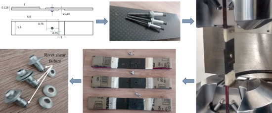
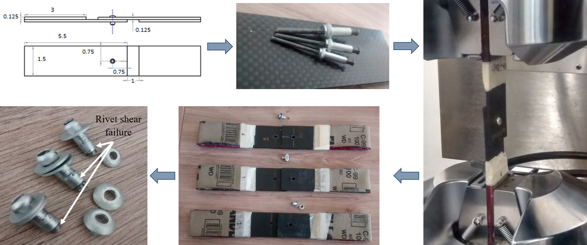
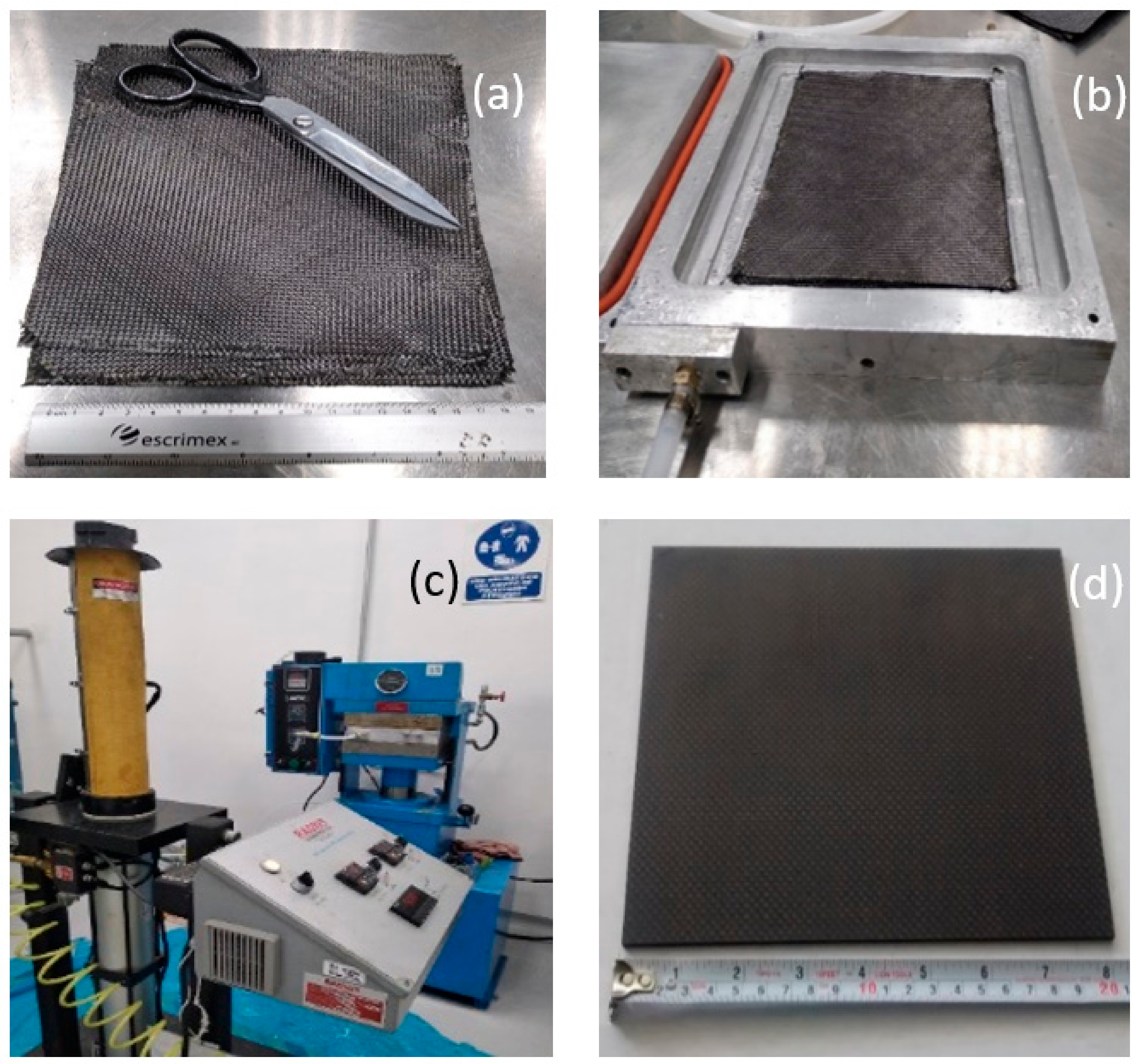
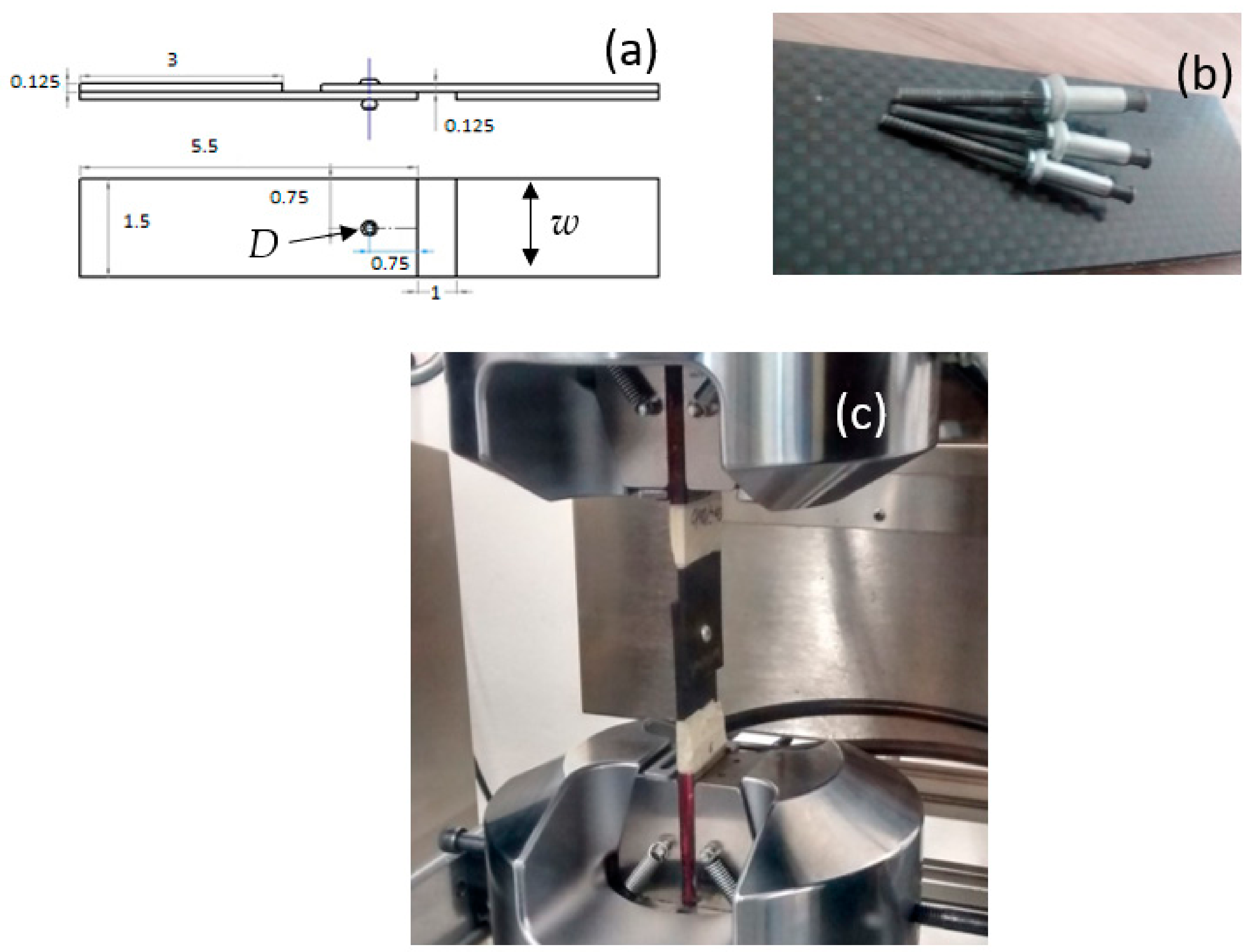
2. Experimental Set-Up

In order to determine the bearing strength of riveted RTM-woven composite joints, the experimental setup went as follows. EPOLAM 2015 epoxy resin supplied by Sika-Axson® Baar, Switzerland and a 3K-70-P carbon fiber plain weave provided by BGF Industries® Cheraw, South Carolina, USA were used. The layup used was quasi-isotropic, with a stacking sequence of [0/452/03]s. The RTM process was carried out with a 2100cc Radius injection system and a hydraulic hot press to hold and heat the aluminum plate mold. The composite polymerization reaction lasted 4 h at 60 °C. A total of 20 composite plates were fabricated: five for reference and five more for the three w/D ratios analyzed. The choice of a woven composite as a study case was a novelty, because most of the riveted composite study cases were set with unidirectional (UD) laminates. An illustration of the RTM process is depicted in Figure 1.
The configuration for the single-lap, single-rivet specimens was defined following the ASTM D5961 instructions. Three different rivet diameters were used: 1/8, 5/32 and 3/16 in (with 12.1, 8.7 and 7.6 width-to-diameter ratios, respectively). Holes were drilled using a tungsten carbide tool with a speed of 3000 RPM to ensure net surface roughness and avoid composite delamination. CherryMAX® (Santa Ana, California, USA) CR3253 aerospace-grade Al5056/stainless steel rivets with protruding oversized heads were used. The rivet tool pressure was set to 7 bar, as mentioned in the datasheet. The overall dimensions of the composite joint specimens and pictures of the joining procedure are shown in Figure 2a,b. The composition, as well as the mechanical properties of the CR3253 alloys, are described in Table 1.
Mechanical tests were carried out in an Instron® 647 (Norwood, MA, USA) universal testing machine with a loading capacity of 100 kN. Testing was performed under displacement control at a crosshead speed of 0.5 in/min (1.27 mm/min). The load displacement curve was recorded until the specimens’ failure (15 repeats of each w/D aspect ratio were performed). Illustrations of the mechanical tests are shown in Figure 2c.
Failure analysis was determined by optical microscopy first to identify fracture mechanisms and second by a computerized tomography (CT) scan to visualize the inner damage length. The CT scan was performed by a GE Phoenix V Tome XM (Skaneateles, NY, USA) computerized tomography system equipped with a 300 kV microfocus with a 1 µm resolution and a 180 kV nanofocus CT with a 0.5 µm resolution.

3. Results and Discussion

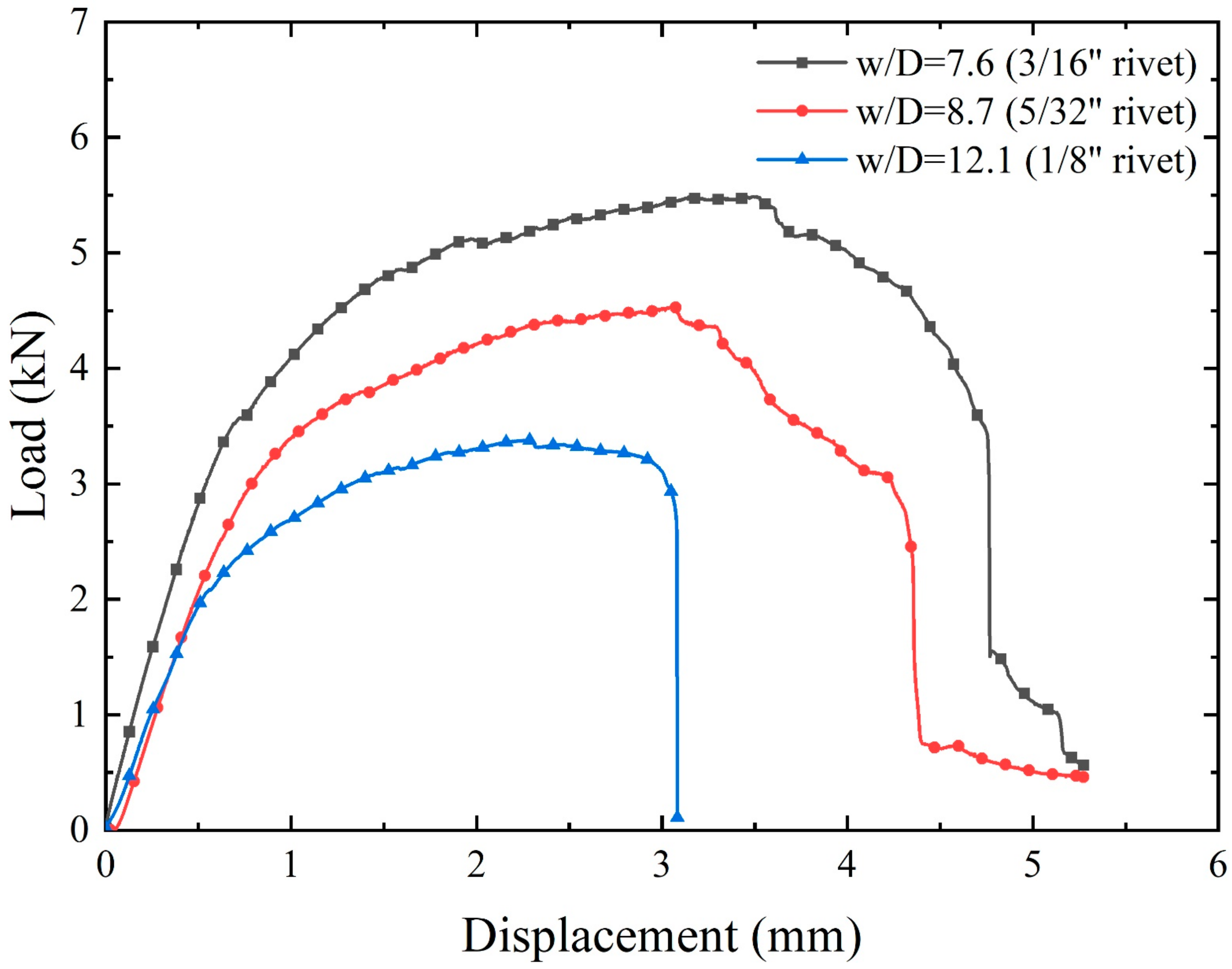
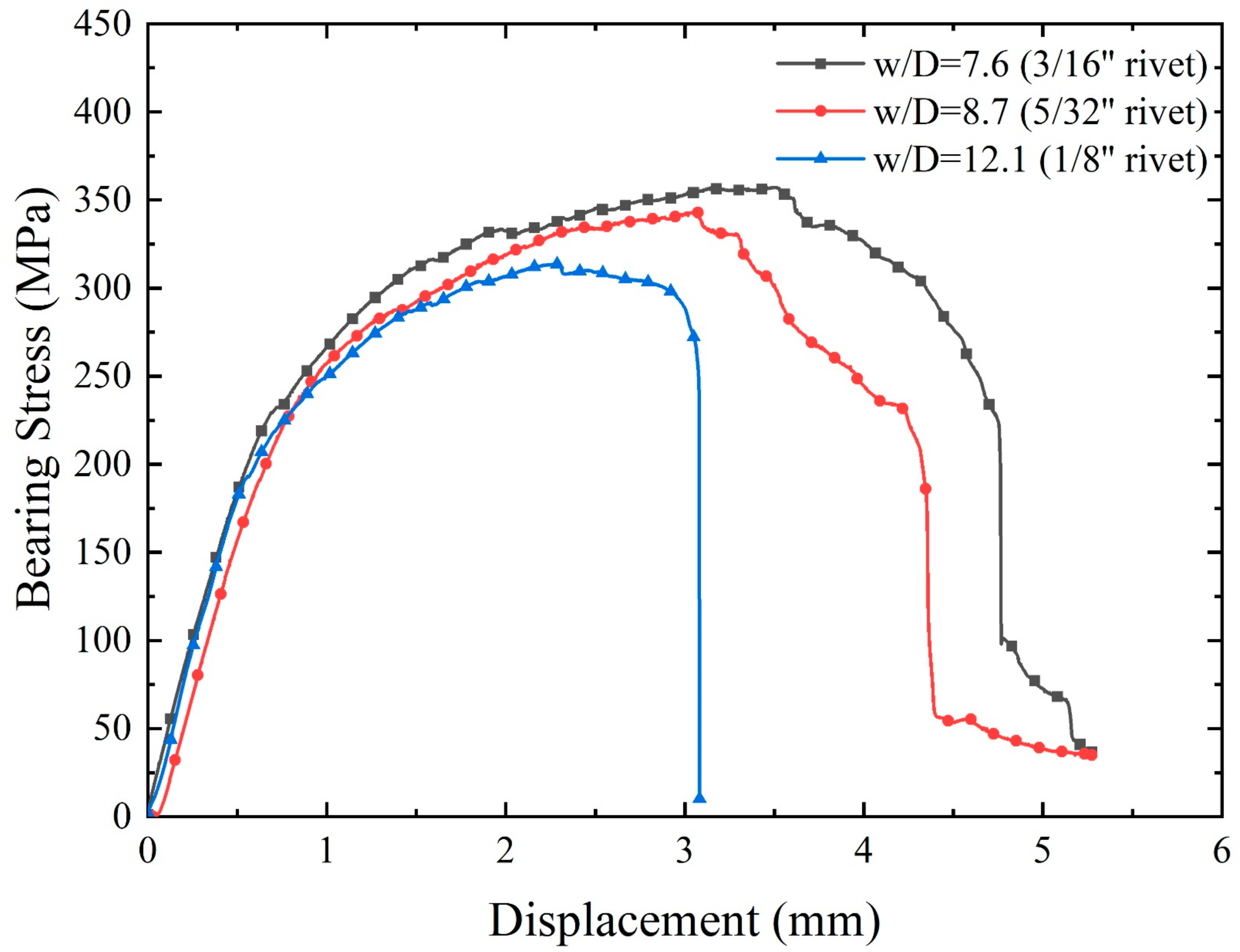
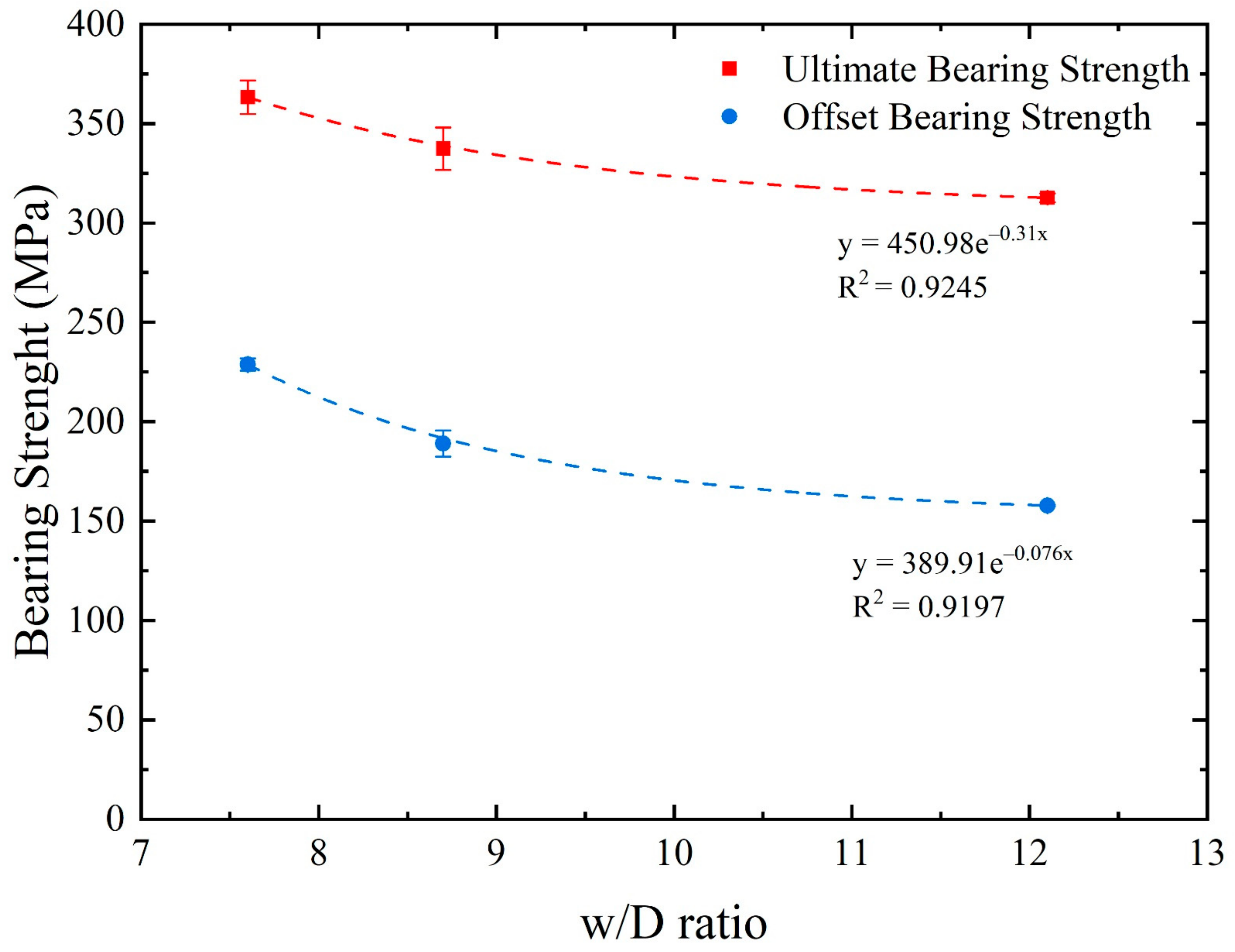
3.1. Calculation of Bearing Strength for Riveted Woven Composites

Figure 3 shows the average load displacement curve for each w/D ratio. For all specimens, three regions were perfectly identified.
The first region comprised the highest stiffness, with linear behavior from the beginning of the test until reaching 0.5–0.75 mm of displacement. The first stiffness was due to (1) the net fit between the rivet and the laminate (no nominal clearance) and (2) sticking caused by friction between the woven laminates. As a consequence, there was not a delay in load take-up, as the rivet started transmitting the load as soon as the composite joint was pulled. Hereafter, the second region showed nonlinear behavior, where a drop in stiffness was observed due to the plastic deformation of the rivet and stick–slip mechanism of the woven laminates. The peak load was reached here, being 3.5 kN, 4.5 kN and 5.5 kN for w/D ratios of 12.08, 8.7 and 7.6, respectively. Finally, in the third region—where a loss of loading capacity was observed for all specimens—the stiffness dropped progressively until the specimen’s failure.
Figure 4 shows the bearing stress curve for each w/D ratio. Equation (1) was used to calculate the bearing stress (σibr) [17]:
σ i b r = P i D h
where Pi is the load at the ith data point, h is the specimen thickness and D is the hole’s diameter. The ultimate bearing strength (Fbru) was computed using the maximum load before failure.
According to the test data, Table 2 shows the 2% offset bearing strength, the ultimate bearing strength and the stiffness ratio for each w/D ratio. The drop in stiffness from Region I to Region II was very significant, being between 82% and 85%. After reaching the ultimate bearing strength, the drop of Region III’s stiffness was between 72% and 83%. Even so, the composite bolted joint extension was similar in Regions II and III. This behavior could be attributed to the hole’s elongation due to the compressive bearing damage observed in previous works [10,11].
As a novelty proposal of this work, a residual bearing strength curve was built, and it is presented in Figure 5. This curve presents the ultimate bearing strength as a function of the w/D ratio. Quadratic adjustment showed values of R2 close to 0.99, which suggests that after a certain w/D ratio, the more perforated specimen was more resistant, which was physically impossible. The exponential fitting had a negative exponent, which indicated that the resistance value went down as the w/D increased, which was occurring.
The average ultimate bearing strength increased as the w/D ratio decreased. This phenomenon was related for two reasons: (1) there was a more extensive transverse section of the rivet to carry the load, and (2) a larger contact area was provided when the rivet diameter increased. McCarthy et al. [3,6] reported that variations in the contact area (fastener composites) caused changes in the joint stiffness and ultimate bearing strength. Zhou et al. [9] concluded that the geometric parameters (such as the w/D and edge-to-diameter (E/D) ratios) should be appropriately chosen. Large geometric parameters do not mean a higher strength. Consequently, as a significant contribution of this work, we can apply this curve for design purposes as a first approach to riveted composite joints’ bearing strengths, in terms of the w/D ratio proposed.

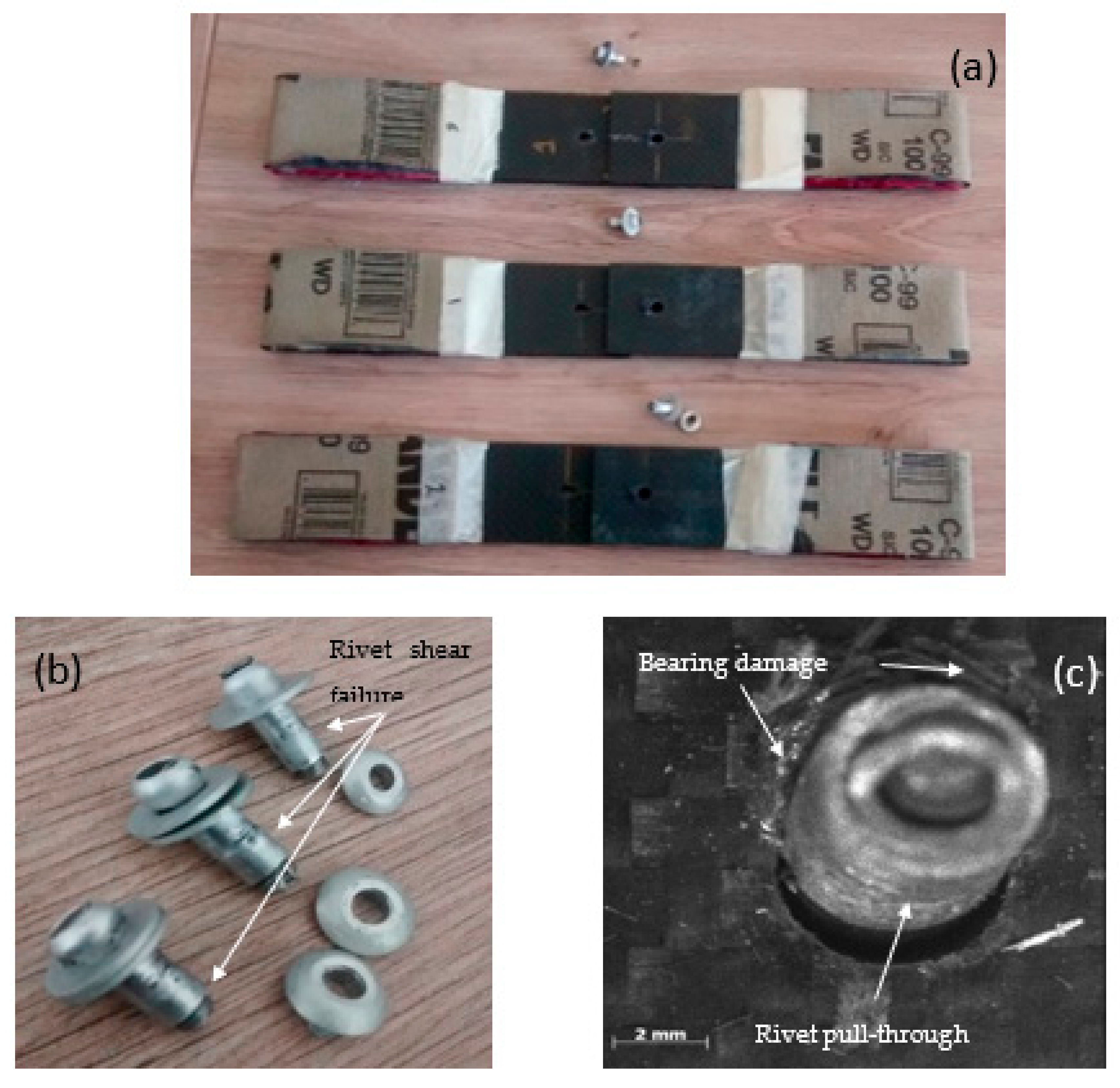
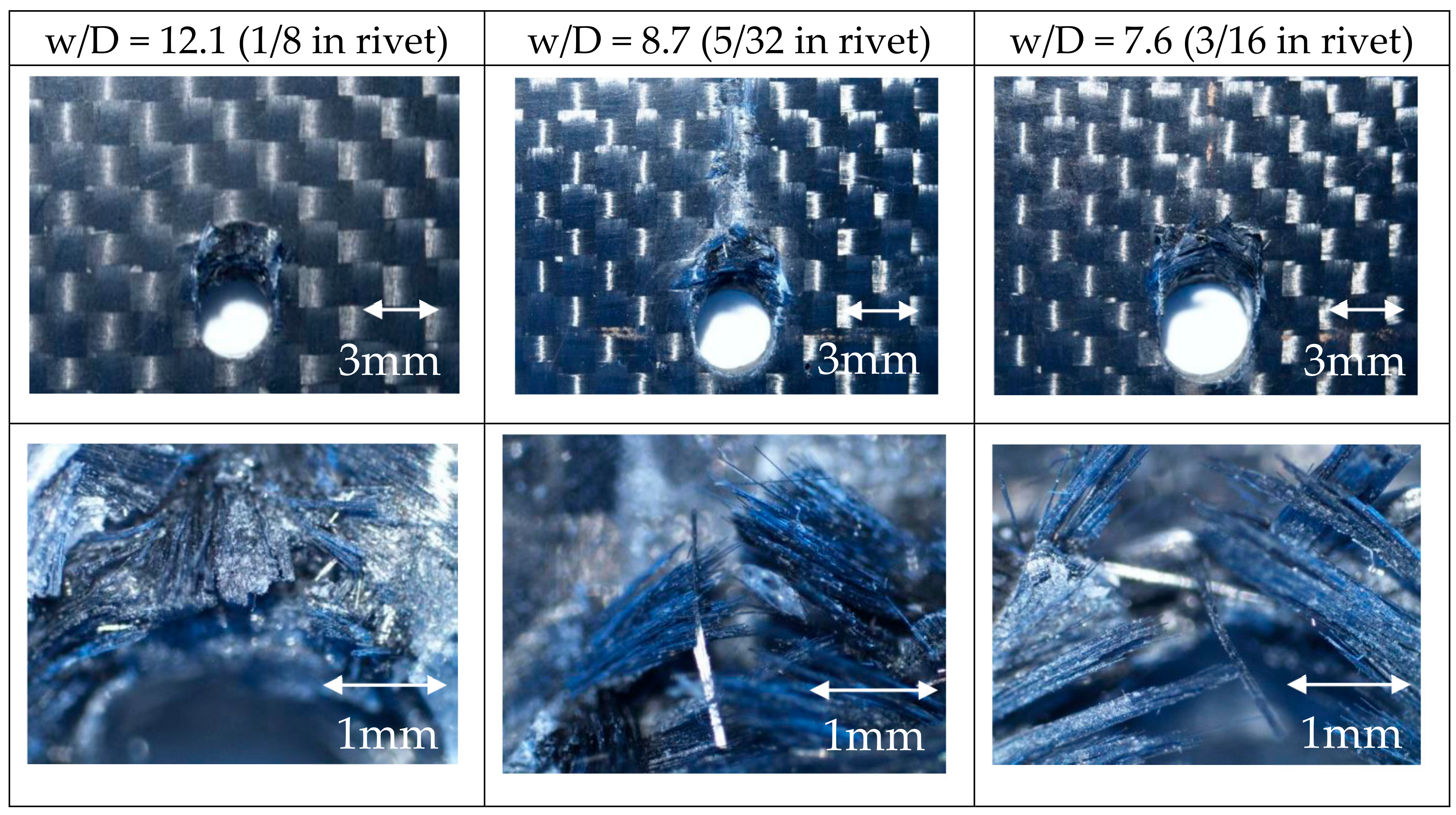
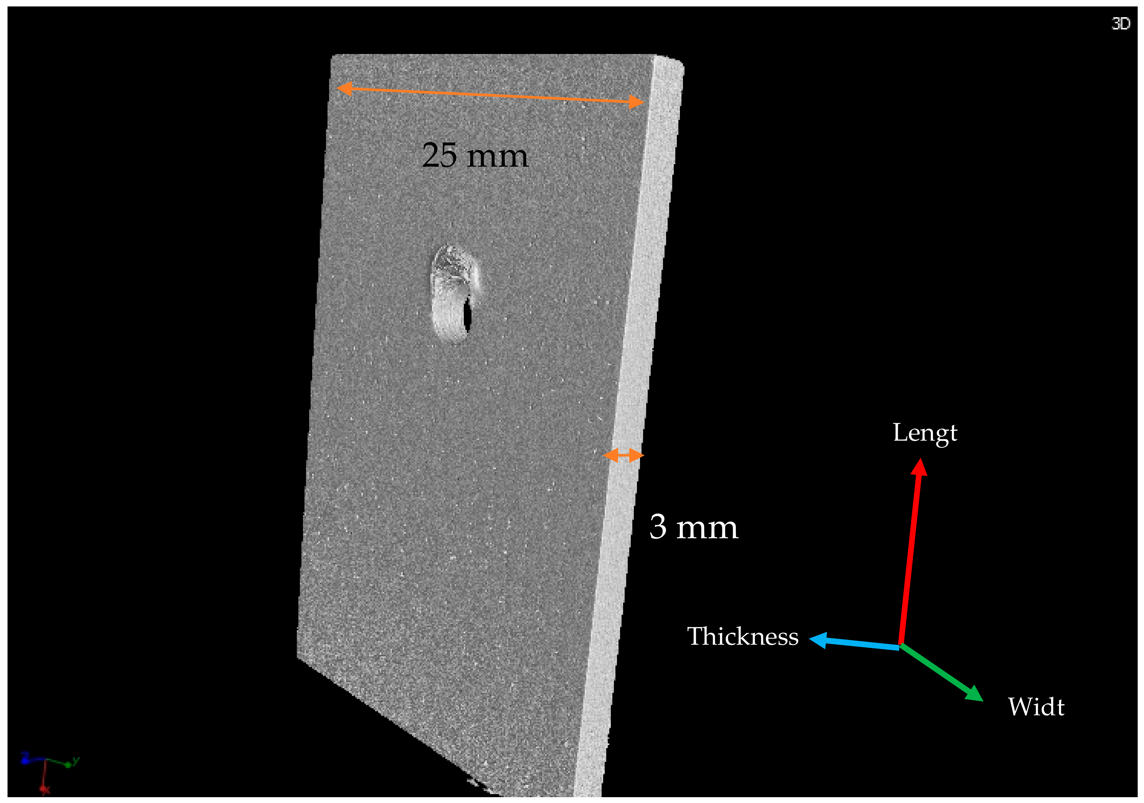
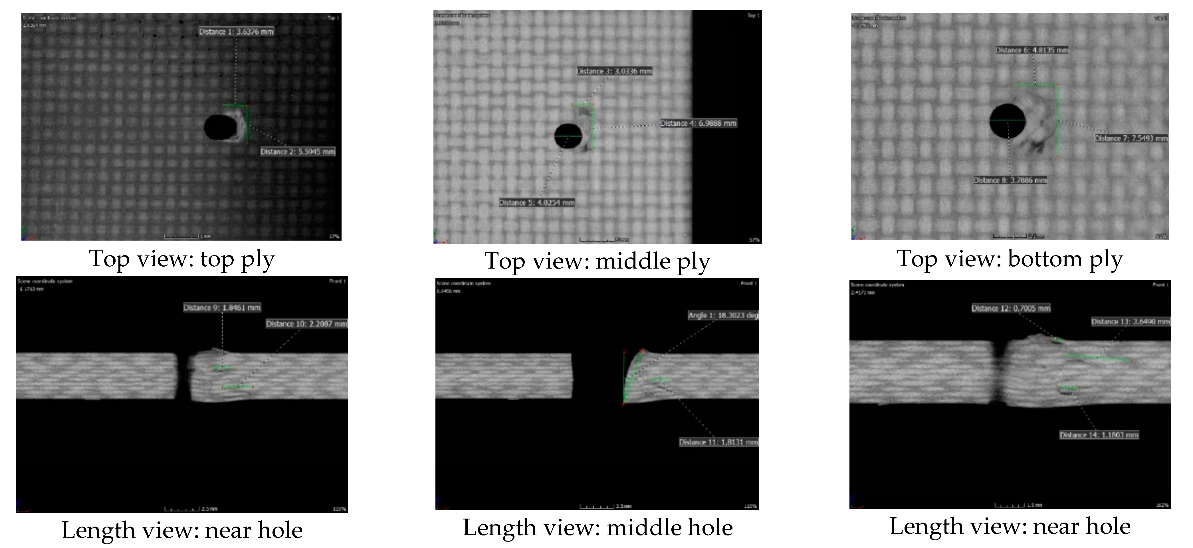
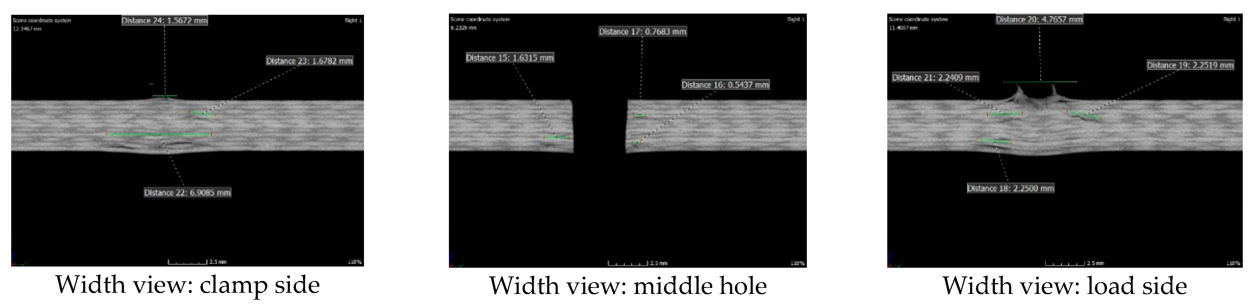
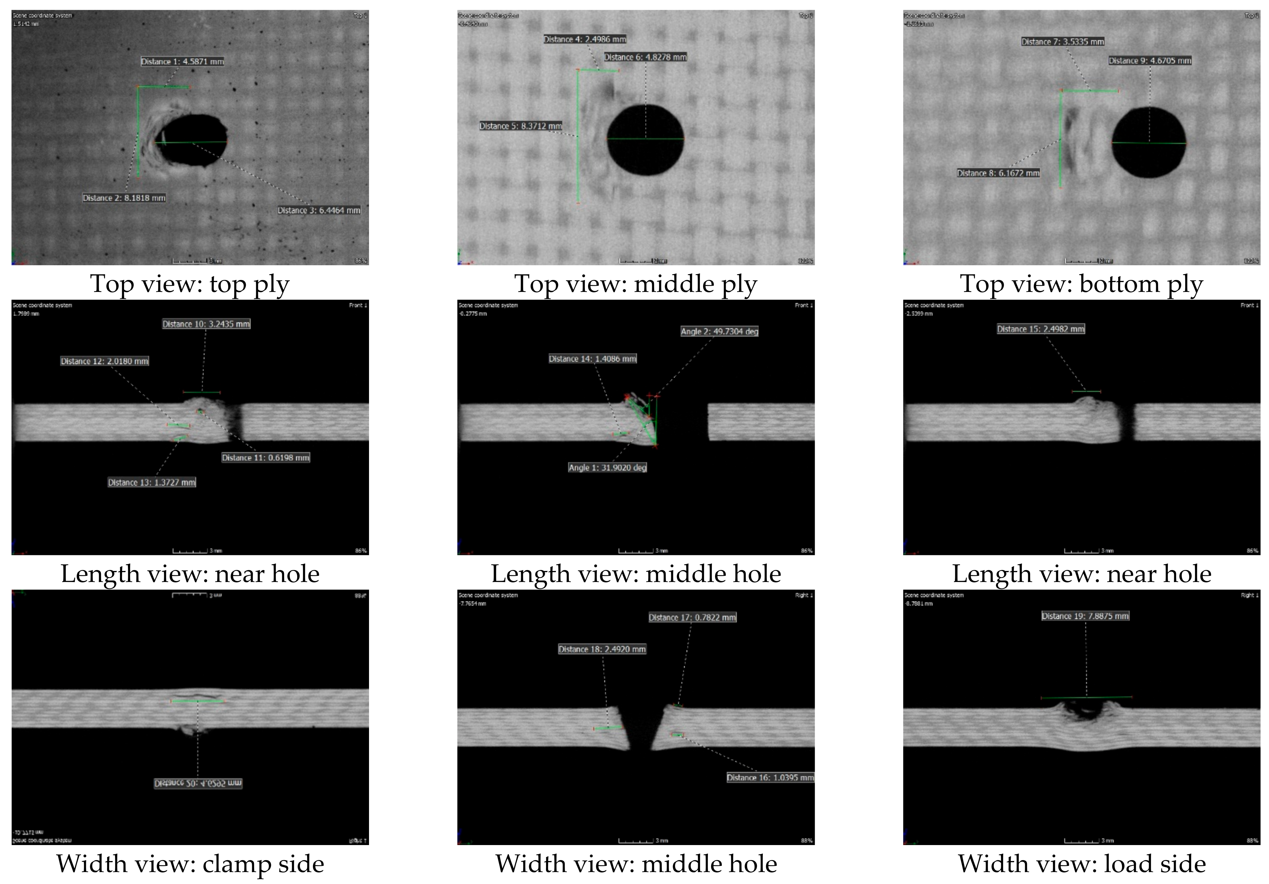
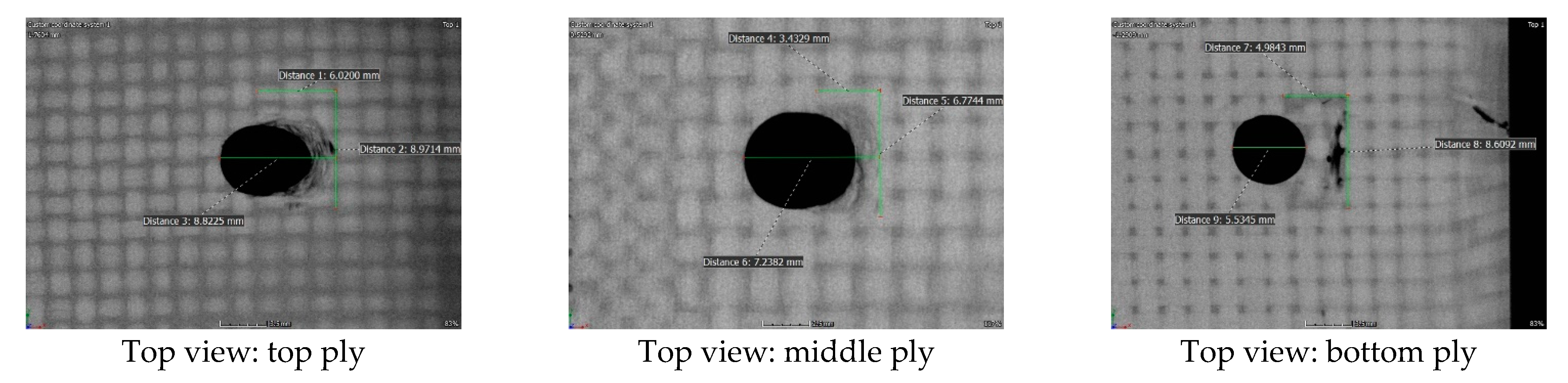
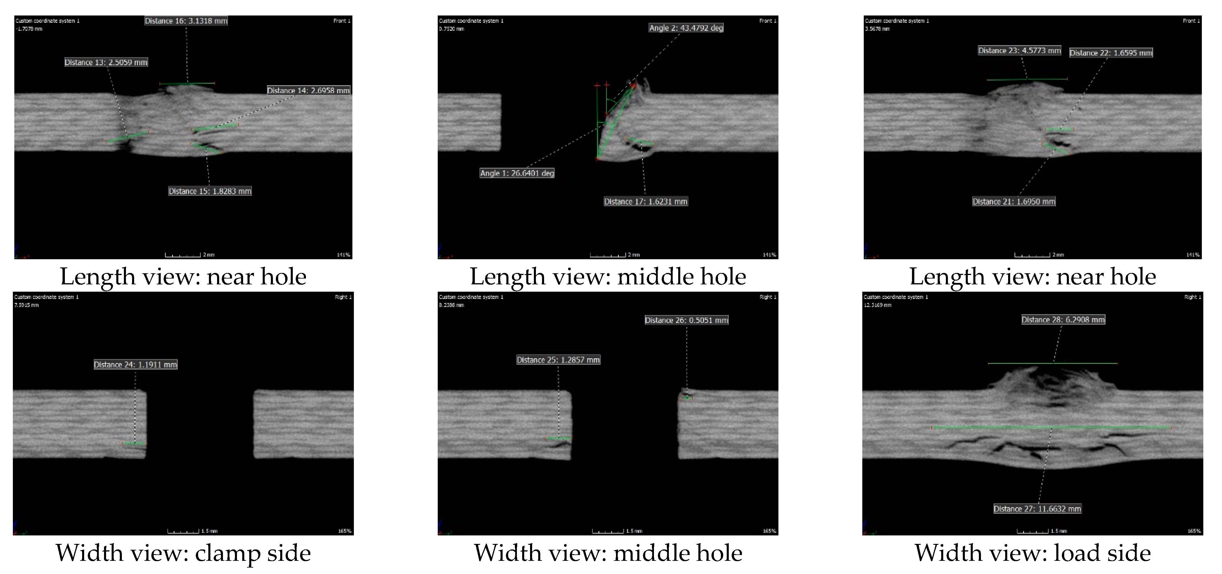
3.2. Fractographic Evaluation

In the mechanical tests of riveted woven composites, the joint’s failure mode was a mixed failure mode because the rivet pull-through, rivet shear failure and bearing damage were observed as the predominant failure mechanisms, as shown in Figure 6.
In order to have a detailed view of the failure mechanisms, a post-failure analysis through optical microscopy was performed as presented in Figure 7. It was found that the rivet joint failed by a combination of bearing failure and rivet pull-through, independent of the w/D ratio.
Concerning fiber buckling and breakage, compressive matrix failure was viewed around the hole, close to the composite–rivet head contact zone as clear evidence of the laminate shear-out. Rivet shear failure was identified as a consequence of the laminate bearing and the rivet alloys’ plastic behavior. These mechanisms were expected because the rivet joints were designed to fail at the bearing [13,17,18] initially. Through ASTM D5961, the failure codes were identified as (1) laminate shear-out, first fastener and fastener thread (S3T) and (2) laminate bearing, first fastener and laminate head side (B1B).
As was stated before by Nezhad et al. [18], on the one hand, the primary mechanism that contributes to joint strength reduction is bearing compressive stress. On the other hand, the principal damage density is caused by laminate bearing delamination at the ultimate failure.
As a complementary analysis, a CT scan was used to estimate the internal damage and crack propagation inside the composite laminate. The complete reconstruction of the CT scan for one of the composite joint specimens is illustrated in Figure 8.
Figure 9, Figure 10 and Figure 11 show the CT scan for the composite joints for each w/D ratio. As can be seen in all the tomography scans, through-thickness shear damage, interlaminar delamination and rivet rotation took place. At the furthest clamp side of the riveted joint, no damage was observed, as expected, because there was no contact with the rivet. At the rivet joint’s load side, fiber buckling and fiber breakage were observed in the rivet hole neighborhood where the rivet introduced the compressive stress. Rotation of the rivet caused fiber detachment and material accumulation in the composite–rivet contact area.
Additionally, delamination was observed mostly at the bottom plies of each composite plate. Most delamination was observed between plies 1–2 and 2–3 of the stacking sequence. As stated in the literature, 0–45° interfaces showed a low fracture toughness that contributed to joint delamination [19].
Independent of the w/D ratio, the rivet joint’s top view shows the elongation of the tight-fit holes due to damage. At the top plies, elongation increased the hole’s diameter by almost 60%. At the middle plane, the hole’s diameter increased by an average of 25%. For the bottom plies, elongation of the hole’s diameter reached at least a 16% augmentation. As reported by McCarthy et al. [6], the clearance influenced the stress state around the hole and therefore led to a significant effect on the initial bearing failure for the fastened joints. Observing the top view, the top ply presented material accumulation as well as material detachment. The middle plane of the plate exhibited weave distortion as well as accumulated damage. Latterly, the bottom ply presented delamination, with the main crack perpendicular to the load and with a crack length at least two times the hole’s diameter.
Regardless of the w/D ratio, the rivet joint’s length view presented a combination of bearing failure and rivet pull-through. Fiber matrix cracking due to the compressive damage could be observed close to the composite–rivet interaction at the load side. The fiber breakage and debonding at the top plies, as a consequence of the rivet’s rotation and the rivet head crushing into the laminate, was also evident. The rotation of the rivet axis varied from 20° to 50°. Finally, at the edges of the hole where the contact area began, the damage extension was also visible due to the presence of microcracks, with a crack size range from 0.6 mm to 2.7 mm. These supplementary failure mechanisms were strongly related to the elongation of the tight-fit holes, causing progressive rivet joint damage [10,17,20,21].
Finally, and not depending on the w/D ratio, the width view illustrates the differences in damage mechanisms between the clamp side and the rivet joint’s load side. At the clamp side, the laminate’s bottom plies were delaminated due to the rivet’s rotation, resulting in the rivet body crushing into the laminate. At the middle position of the hole, lateral cracking was observed, with a crack length range from 0.5 mm to 2.5 mm. This lateral damage could have originated from the drilling process and been magnified due to rivet–composite sliding. Conclusively, at the load side, the damage extension was up to 7.8 mm. In this zone, lateral delamination occurred at top plies (0°/45°) and (45°/45°), and extensive fiber matrix cracking, material accumulation and material detachment was observed because of the rivet head crushing into the laminate. The bearing failure mechanism at this zone was most visible because this type of joint is designed to fail in this manner.

4. Conclusions

This paper has presented the mechanical response and failure mechanisms of riveted woven carbon/epoxy composites fabricated by RTM. The study was focused on joint performance by using a practical test case comparing three different rivet diameters: 1/8, 5/32 and 3/16 in. Most of the riveted composite study cases were UD-related. Here, the study case dealt with woven composites, which was a novelty for the work.
A comparison of the three joints was performed. The 3/16 in rivet joint had the most significant load-carrying capacity, followed by the 5/32 in and 1/8 in rivet joints. The wider the diameter, the bigger the expected load carrying capacity. Even when the bearing stress had the same trend, the difference between the bearing ultimate strengths was tighter for each rivet diameter.
A proposal of this work is a residual bearing strength curve. This curve presents the ultimate bearing strength as a function of the w/D ratio. The proposed curve shows that the average ultimate bearing strength increases as the w/D ratio decreases.
The failure mode of the joint was a mixed failure mode. The rivet pull-through, rivet failure, bearing damage and laminate shear-out were observed as the predominant failure mechanisms per ASTM D5961.
Detailed progressive damage was shown by means of a CT scan. At the load side of the rivet joint, fiber buckling and fiber breakage were observed. Rotation of the rivet caused fiber detachment and material accumulation in the composite–rivet contact area.

Author Contributions

Conteptualization, resources, writing—original draft preparation and investigation, M.T.-A.; formal analysis and investigation, M.d.J.B.-M.; writing—review and editing, E.A.F.-U.; investigation, R.P.-M.; investigation, O.A.J.-A.; methodology, visualization and writing—review, P.O. All authors have read and agreed to the published version of the manuscript.

Funding

This research was funded by AEM and CONACYT through the Research Fund for the Development of Space Activities (FIDAE), grant number 275783 and by CONACYT through the Institutional Fund for Regional Promotion for Scientific, Technological and Innovation Development (FORDECYT), grant number 297708. The APC was funded by FORDECYT, grant number 297708.

Institutional Review Board Statement

Not applicable.

Informed Consent Statement

Not applicable.

Data Availability Statement

Data is contained within the article. More data presented in this study are available on request from the corresponding author. The data are not publicly available due to privacy restrictions.

Acknowledgments

Mauricio Torres, Edgar Franco and Ruben Perez convey their special appreciation to the CONACYT Researchers Program (Catedras CONACYT). M.J. Bolom-Martínez gives thanks to the Institut Clément Ader for his research internship during his master’s degree. CT scanning was performed by Marco Paredes, and the RTM procedure was inspected by Víctor Gómez.

Conflicts of Interest

The authors declare no conflict of interest.

References

  1. Report, F. Assessment of Damage Tolerance Standard Test Methods and Development of Crack Growth and Delamination Database for Composite Structures; Air Traffic Organization Operations Planning Office of Aviation Research and Development: Washington, DC, USA, 2009. [Google Scholar]
  2. Xiong, Y. An analytical method for failure prediction of multi-fastener composite joints. Int. J. Solids Struct. 1996, 33, 4395–4409. [Google Scholar] [CrossRef]
  3. McCarthy, C.T.; McCarthy, M.A.; Gilchrist, M.D. Predicting failure in multi-bolt composite joints using finite element analysis and bearing-bypass diagrams. Key Eng. Mater. 2005, 293–294, 591–598. [Google Scholar] [CrossRef]
  4. Egan, B.; McCarthy, C.T.; McCarthy, M.A.; Gray, P.J.; O’Higgins, R.M. Static and high-rate loading of single and multi-bolt carbon-epoxy aircraft fuselage joints. Compos. Part A Appl. Sci. Manuf. 2013, 53, 97–108. [Google Scholar] [CrossRef] [Green Version]
  5. Cao, Z.; Cardew-Hall, M. Interference-fit riveting technique in fiber composite laminates. Aerosp. Sci. Technol. 2006, 10, 327–330. [Google Scholar] [CrossRef]
  6. Mccarthy, C.; Mccarthy, M. Experimental and computational studies of mechanically fastened joints in composite aircraft structures. In Proceedings of the 1st CEAS European Air and Space Conference, Berlin, Germany, 10–13 September 2007; German Society for Aeronautics and Astronautics: Berlin, Germany, 2007; pp. 717–726. [Google Scholar] [CrossRef]
  7. Di Franco, G.; Fratini, L.; Pasta, A. Influence of the distance between rivets in self-piercing riveting bonded joints made of carbon fiber panels and AA2024 blanks. Mater. Des. 2012, 35, 342–349. [Google Scholar] [CrossRef]
  8. Camanho, P.P.; Lambert, M. A design methodology for mechanically fastened joints in laminated composite materials. Compos. Sci. Technol. 2006, 66, 3004–3020. [Google Scholar] [CrossRef]
  9. Zhou, S.; Wang, Z.; Zhou, J.; Wu, X. Experimental and numerical investigation on bolted composite joint made by vacuum assisted resin injection. Compos. Part B Eng. 2013, 45, 1620–1628. [Google Scholar] [CrossRef]
  10. Bielawski, R.; Kowalik, M.; Suprynowicz, K.; Rządkowski, W.; Pyrzanowski, P. Investigation of Riveted Joints of Fiberglass Composite Materials. Mech. Compos. Mater. 2016, 52, 199–210. [Google Scholar] [CrossRef]
  11. Ataş, A.; Soutis, C. Strength prediction of bolted joints in CFRP composite laminates using cohesive zone elements. Compos. Part B Eng. 2014, 58, 25–34. [Google Scholar] [CrossRef]
  12. Sachse, R.; Pickett, A.K.; Essig, W.; Middendorf, P. Experimental and numerical investigation of the influence of rivetless nut plate joints on fatigue crack growth in adhesively bonded composite joints. Int. J. Fatigue 2017, 105, 262–275. [Google Scholar] [CrossRef]
  13. Kradinov, V.; Hanauska, J.; Barut, A.; Madenci, E.; Ambur, D.R. Bolted patch repair of composite panels with a cutout. Compos. Struct. 2002, 56, 423–444. [Google Scholar] [CrossRef]
  14. Pierce, R.S.; Falzon, B.G. Modelling the size and strength benefits of optimised step/scarf joints and repairs in composite structures. Compos. Part B Eng. 2019, 173, 107020. [Google Scholar] [CrossRef]
  15. Yoo, S.Y.; Kim, C.H.; Kweon, J.H.; Choi, J.H. The structural analysis and strength evaluation of the rivet nut joint for composite repair. Compos. Struct. 2016, 136, 662–668. [Google Scholar] [CrossRef]
  16. Baker, A.; Wang, J. Proposed through-life management approaches for adhesively bonded repair of primary structures. Int. J. Adhes. Adhes. 2018, 87, 151–163. [Google Scholar] [CrossRef]
  17. Fukada, Y. Bearing strength of carbon fibre/epoxy laminate with direct measurement of hole deformation. Adv. Compos. Mater. 2013, 22, 311–325. [Google Scholar] [CrossRef]
  18. Nezhad, H.Y.; Egan, B.; Merwick, F.; McCarthy, C.T. Bearing damage characteristics of fibre-reinforced countersunk composite bolted joints subjected to quasi-static shear loading. Compos. Struct. 2017, 166, 184–192. [Google Scholar] [CrossRef] [Green Version]
  19. Torres, M.; Tellez, R.A.; Hernández, H.; Camps, T. Mode I interlaminar fracture toughness of carbon-epoxy coupons with embedded ceramic sensors. Adv. Polym. Technol. 2018, 37, 2294–2302. [Google Scholar] [CrossRef]
  20. Zhang, J.; Liu, F.; Zhao, L.; Fei, B. A novel characteristic curve for failure prediction of multi-bolt composite joints. Compos. Struct. 2014, 108, 129–136. [Google Scholar] [CrossRef]
  21. Rao, H.M.; Kang, J.; Huff, G.; Avery, K. Impact of specimen configuration on fatigue properties of self-piercing riveted aluminum to carbon fiber reinforced polymer composite. Int. J. Fatigue 2018, 113, 11–22. [Google Scholar] [CrossRef]
Figure 1. Manufacturing of resin transfer molding (RTM)-woven composites for riveted joints. (a) Carbon fabric cutting, (b) fabric placed in an RTM mold, (c) the RTM and hot press process and (d) the finished composite plate.
Aerospace 08 00105 g001
Figure 2. (a) Schematic of the woven composite rivet joint specimen (dimensions in inches), (b) illustration of the three employed rivet sizes (1/8, 5/32 and 3/16 in) and (c) illustration of the mechanical test of composite joints.
Aerospace 08 00105 g002
Figure 3. Load displacement curve of the riveted woven composites for each w/D ratio.
Aerospace 08 00105 g003
Figure 4. Bearing strength curves of riveted woven composites for each w/D ratio.
Aerospace 08 00105 g004
Figure 5. Proposal of a residual strength curve for single-joint, single-rivet woven composites.
Aerospace 08 00105 g005
Figure 6. Post-failure macroscopic inspection of the single-joint, single-rivet woven composites. (a) Failed coupons, (b) rivets’ shearing and (c) bearing failure.
Aerospace 08 00105 g006
Figure 7. Post-failure analysis using optical microscopy. First row: bearing failure exhibited in each w/D ratio. Second row: fibers buckling, fiber breakage and matrix compressive failure at the composite–rivet contact zone for each w/D ratio.
Aerospace 08 00105 g007
Figure 8. A computerized tomography scan’s general reconstruction for the woven composite rivet joint.
Aerospace 08 00105 g008
Figure 9. Computerized tomography scan for the woven composite rivet joint with a w/D = 12.1 (1/8 in rivet).
Aerospace 08 00105 g009aAerospace 08 00105 g009b
Figure 10. Computerized tomography scan for the woven composite rivet joint with a w/D = 8.7 (5/32 in rivet).
Aerospace 08 00105 g010
Figure 11. Computerized tomography scan for the woven composite rivet joint with a w/D = 7.6 (3/16 in rivet).
Aerospace 08 00105 g011aAerospace 08 00105 g011b
Table 1. Composition of CR3253 aerospace-grade rivet alloys.
Rivet ElementAlloyUltimate Strength (MPa)Yield Strength (MPa)Elongation (%)
SleeveAl 505633015235
Stem15-7 PH111777927
Lock collarA286109171226
Table 2. Bearing properties for single-lap, single-rivet woven composite joints.
Rivet Diameter1/8 in5/32 in3/16 in
w/D ratio12.18.77.6
Region I stiffness (kN/mm)4.03 ± 0.454.23 ± 0.434.89 ± 0.24
Region II stiffness (kN/mm)0.72 ± 0.0540.77 ± 0.0380.75 ± 0.16
Region III stiffness (kN/mm)−0.72 ± 0.269−1.18 ± 0.215−1.37 ± 0.019
Region II/Region I stiffness ratio0.180.180.15
Region III/Region I stiffness ratio−0.17−0.28−0.28
2% offset bearing strength (MPa)157.81 ± 0.42188.96 ± 6.63228.80 ± 6.63
Ultimate bearing strength (MPa)312.62 ± 2.16337.35 ± 10.69363.22 ± 8.45
Publisher’s Note: MDPI stays neutral with regard to jurisdictional claims in published maps and institutional affiliations.

