Article

Aspect Ratio Driven Relationship between Nozzle Internal Flow and Supersonic Jet Mixing

Department of Aerospace Engineering and Engineering Mechanics, University of Cincinnati, Cincinnati, OH 45221, USA
*
Author to whom correspondence should be addressed.
Aerospace 2021, 8(3), 78; https://doi.org/10.3390/aerospace8030078
Submission received: 22 February 2021 / Revised: 5 March 2021 / Accepted: 5 March 2021 / Published: 16 March 2021

Abstract

:
This work attempts to connect internal flow to the exit flow and supersonic jet mixing in rectangular nozzles with low to high aspect ratios (AR). A series of low and high aspect ratio rectangular nozzles (design Mach number = 1.5) with sharp throats are numerically investigated using steady state Reynolds-averaged Navier−Stokes (RANS) computational fluid dynamics (CFD) with k-omega shear stress transport (SST) turbulence model. The numerical shadowgraph reveals stronger shocks at low ARs which become weaker with increasing AR due to less flow turning at the throat. Stronger shocks cause more aggressive gradients in the boundary layer resulting in higher wall shear stresses at the throat for low ARs. The boundary layer becomes thick at low ARs creating more aerodynamic blockage. The boundary layer exiting the nozzle transforms into a shear layer and grows thicker in the high AR nozzle with a smaller potential core length. The variation in the boundary layer growth on the minor and major axis is explained and its growth downstream the throat has a significant role in nozzle exit flow characteristics. The loss mechanism throughout the flow is shown as the entropy generated due to viscous dissipation and accounts for supersonic jet mixing. Axis switching phenomenon is also addressed by analyzing the streamwise vorticity fields at various locations downstream from the nozzle exit.

1. Introduction

Rectangular cross-section nozzles have been a topic of interest for many researchers, dating back to the early 1990s [1,2,3,4,5], and recently [6,7,8,9,10,11,12,13,14,15,16,17]. Low noise emissions, enhanced mixing and thrust vectoring are some of the benefits of rectangular nozzles [2,3,4,9]. Along with experimental data, computational fluid dynamics (CFD) simulations of nozzles are also becoming more mainstream [16,17,18] in the design-analysis process. Some of the previous literature focused on comparing the rectangular nozzles to their circular counterparts in terms of noise characteristics using large eddy simulations (LES) [9]. Many researchers [9,10,11,12,16] also investigated the noise sources which include but are not limited to turbulent mixing noise, broadband noise and screech tones. A lot of focus has also been on understanding the effect of nozzle cross section, adding guide vanes, chevrons, etc., to enhance the mixing downstream [13,15]. Researchers at the University of Cincinnati [7,10,12] have experimentally investigated the effect of rectangular jets exhausting over a flat surface on noise generation, shear layer development and screech tones. Among these studies, the rectangular nozzle with aspect ratio (AR) 2 has been heavily investigated experimentally by the researchers at the University of Cincinnati. Large eddy simulations (LES) have been conducted by Viswanath et al. [9] to understand the noise characteristics in more detail. The effect of the nozzle-exit boundary layer on near-field development in axisymmetric nozzles at high subsonic conditions has been addressed by Trumper et al. [19]. Other researchers have looked at the effect of aspect ratio on jet mixing at subsonic flow conditions using RANS CFD [13]. Yu et al. [17] investigated the axis switching phenomenon in low aspect ratio rectangular jets at relatively low Reynolds numbers. Although there is a significant amount of literature available on rectangular jets in general, limited numerical literature is available which connects the nozzle internal flow to the nozzle exit flow and supersonic jet mixing at low as well as high AR nozzles. Therefore, this work attempts to bridge that gap. High aspect ratio nozzles have been a topic of interest for the distributed propulsion system in the recent work published by Dippold [13] and it was focused on subsonic and transonic flow regime. Although LES would give more insights into the noise aspect as demonstrated in reference [9,14], it is numerically expensive and not in the scope of the current work. The use of computationally inexpensive methods such as RANS has been examined by Georgiadis et al. [20] in the design-analysis process of exhaust nozzles. Their work concluded that “RANS methods can frequently capture the trends exhibited by experiments when altering the geometry or flow conditions of the analysis subject. This fact coupled with the fact that RANS solutions are relatively computationally inexpensive means that RANS methods still have a place for designing nozzle systems” [20]. Recent work by Dippold [13] also demonstrated the use of RANS in design analysis of rectangular nozzles. Since the goal of the present work is to analyze the effect of AR on internal flow and jet mixing at a preliminary level, RANS CFD is deemed appropriate.
The simulations in this work represent the nozzle operation at ambient conditions rather than a nozzle operating at higher altitudes. The scope of the current work is also limited to cold jet, i.e., jet temperature ratio (TR) with TR = 1. As mentioned previously, the baseline nozzle has a sharp throat which causes shock waves inside the nozzle. The author has previously established the effect of smoothly contouring the nozzle walls on the flow field and the structural integrity of the nozzle by conducting fluid-thermal-structural interaction simulations [21,22,23]. While it is possible to contour the nozzle walls, it may not be always feasible to maintain a smooth nozzle wall contour, if the nozzles have variable area ratio. One such example is during the afterburner operation. More details on this can be found in reference [24], page 508. Hence, the nozzles considered in this study have sharp throats, meaning that the transition from converging to diverging section is not smooth but is a straight line which causes a sharp throat.

2. Methodology

The AR2 nozzle is considered as the baseline nozzle since the experimental data was available from the University of Cincinnati [7] to perform benchmark validation of the CFD test case.
To demonstrate the relationship between the internal and nozzle exit flow behavior, both low (1, 2, 3) and high (8, 12) AR nozzles are chosen which translate to five CFD cases excluding the validation cases. Each CFD case took about ~7–10 h to converge with ~4–8 million of mesh count (depending on AR) on twenty Intel Xeon (E5-2660 v3 at 2.60 Gigahertz) processor cores. This increased the total simulation time significantly. Since the focus in this paper was to connect wall bounded flow with nozzle exit flow and jet mixing at different aspect ratios, analyzing the averaged quantities was imperative to create good baseline data before moving forward with scale-resolving and computationally expensive methods such as LES. Considering these facts, RANS was deemed sufficient with the necessary trade-offs.

2.1. Physics Setup

The 3D steady RANS equations are solved for the compressible flow of air, modeled as an ideal gas. Menter’s k-omega SST turbulence model is used which addresses the wall bounded flow and external jet mixing. Equations (1)–(3) (from reference [25]) represent the equations for conservation of mass, momentum, and energy. In Equation (1), ρ is the density, i.e., the mass per unit volume, and v is the continuum velocity. In Equation (2), ⊗ denotes the outer product, f b is the resultant of the body forces per unit volume acting on the continuum, and σ is the stress tensor. For a fluid, the stress tensor is often written as the sum of normal stresses and shear stresses, σ = p I + T , p is the pressure and T is the viscous stress tensor. In Equation (3), E is the total energy per unit mass, q is the heat flux, and S E is an energy source per unit volume. All simulations are conducted in commercial software Star-CCM + v11.02. A density-based solver is used, and a second order upwind scheme is used for spatial discretization. Roe-FDS is used for convective fluxes. Grid sequencing is used for faster convergence with a fixed CFL without ramping. Nozzle temperature ratio, i.e., TR = 1, is used, where the freestream conditions represent atmospheric temperature and pressure, i.e., 300 K and 101,325 Pa, respectively. The results of the numerical validation, mesh sensitivity and turbulence model study are presented in the author’s previous publication [22] and MS thesis [23]. They are not presented here for brevity. For further details, see reference [22].
· ( ρ v ) = 0  
. ( ρ v v ) = · ( p I ) + · T + f b
· ( ρ E v ) = f b   · v + · ( v · σ ) · q + S E

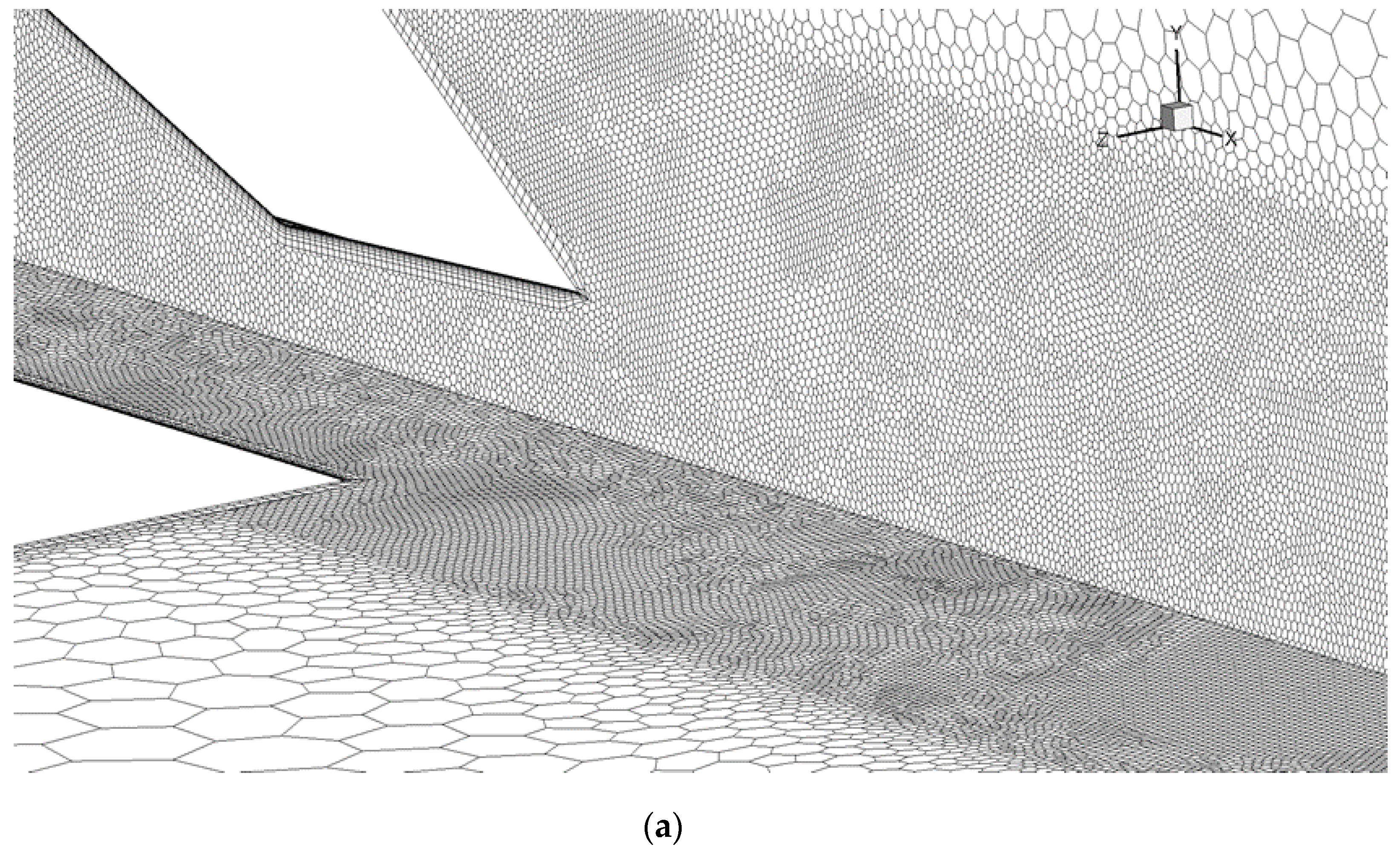
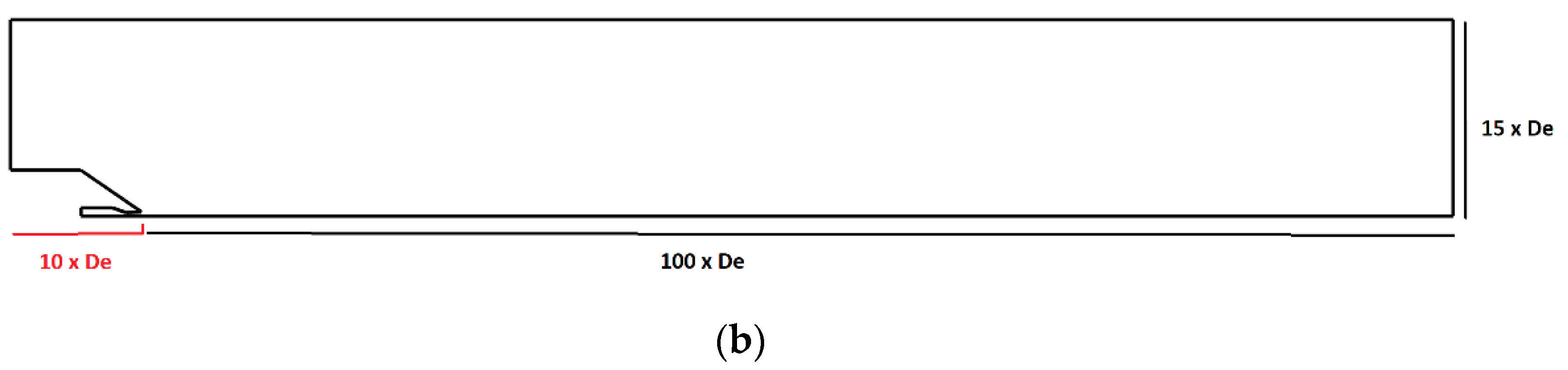
2.2. Computational Domain, Mesh, and Boundary Conditions

The computational domain extends 100 equivalent diameters (De) downstream from the nozzle exit, 15 times De in Y direction and 10 times De upstream to allow for the flow convergence without having a numerical impact of the freestream boundaries on the jet. To capture the shock wave formation and the jet, volumetric refinements are used which are about 1% of the base size of 50 mm. 15 prism layers are used with an expansion factor of 1.5 for the boundary layer mesh. Wall y+ values are less than 3 along the nozzle walls. Figure 1a shows the volumetric mesh refinements and boundary layer mesh on the minor and major axis symmetry planes for the baseline nozzle. Figure 1b shows the entire computational domain.
The nozzle inlet is modeled as a stagnation inlet with pressure 3.67 times the atmospheric pressure and an inlet total temperature of 300 K, therefore, the jet is referred to as cold. Nozzle walls are modeled as no slip adiabatic walls and the domain boundaries are modeled as freestream with atmospheric pressure, temperature, and freestream Mach number = 0.1. Symmetry boundary conditions are used at the minor axis symmetry plane and major axis symmetry plane to save computational time. Therefore, only the quarter section of the domain is simulated.

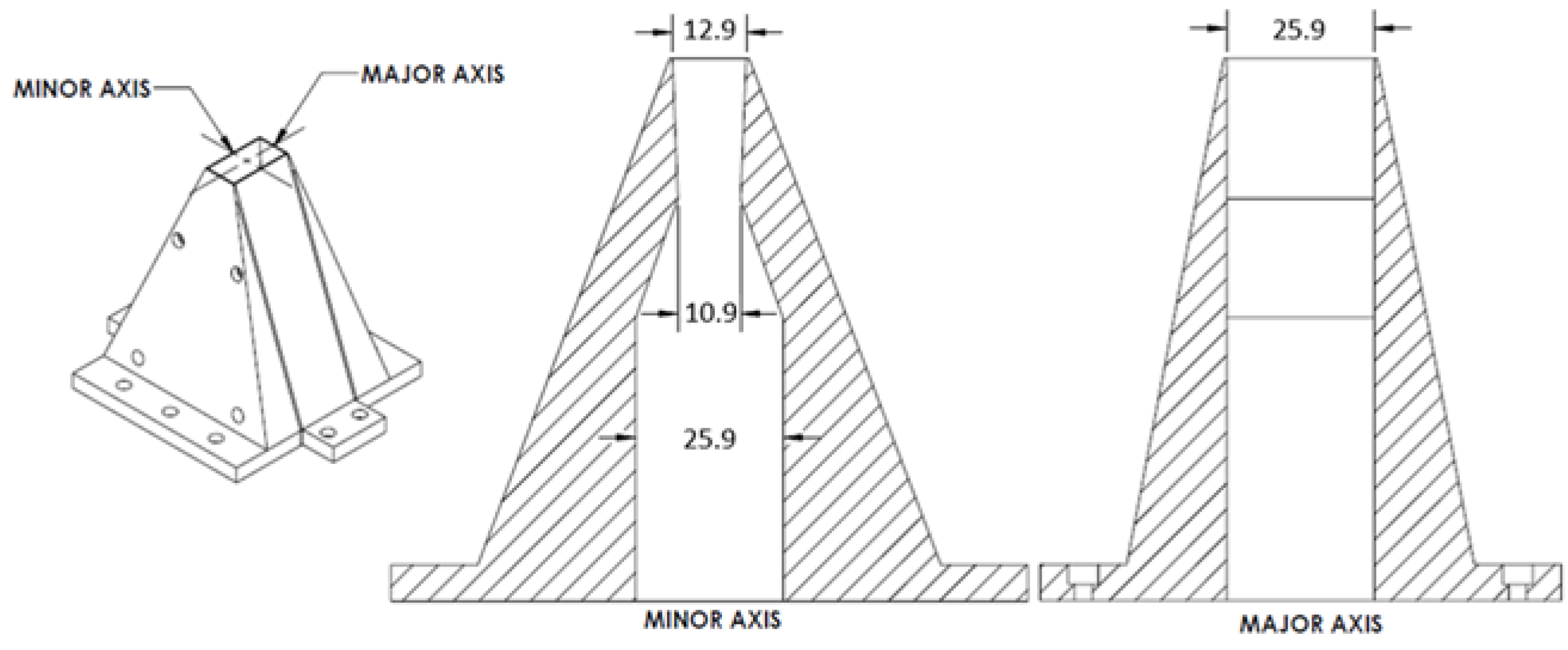
2.3. Nozzle Geometries and CFD Cases

The nozzle aspect ratio in this work is defined as the ratio of the nozzle width to the nozzle height at the nozzle exit (see Equations (4) and (5)). The nozzle exit area (Aexit) is known from the baseline geometry (Figure 2). The baseline geometry is modified to obtain equivalent low and high aspect ratio nozzles by keeping the exit-to-throat area ratio and nozzle-exit equivalent diameter constant. Therefore, the Reynolds number at nozzle exit is the same for all geometries. This created a better reference for comparison by only changing the nozzle aspect ratio and avoiding the Reynolds number effect on the flow. As mentioned previously, the nozzle wall profile is created using a straight line which caused a sharp throat. This gave a total of 5 nozzle geometries with AR = 1, 2, 3 and 8, 12 with design Mach number = 1.5. The goal is to understand the internal flow behavior and jet mixing characteristics at lower and higher ARs than the baseline nozzle, hence the choice of AR.
The height and width at nozzle exit are calculated using Equations (4) and (5)
h e i g h t = A e x i t A R  
A R =   w i d t h h e i g h t  
The abbreviations for CFD cases for various AR nozzles are listed in Table 1 and are used from here onwards.

Validation and Verification

As mentioned previously, the experimental data of the baseline (AR2) nozzle was available from University of Cincinnati [7]. Further details regarding the numerical validation, turbulence model study and mesh sensitivity study can be found in the author’s previous work in reference [22]. To ensure numerical convergence, various quantities such as the thrust, mass flow rate, discharge coefficient were monitored at the nozzle-exit plane in addition to the residuals of continuity, momentum, and energy equation. The simulations were run until these quantities were unchanged over several iterations. This ensured that all simulations reached numerical convergence and steady state behavior.

3. Results

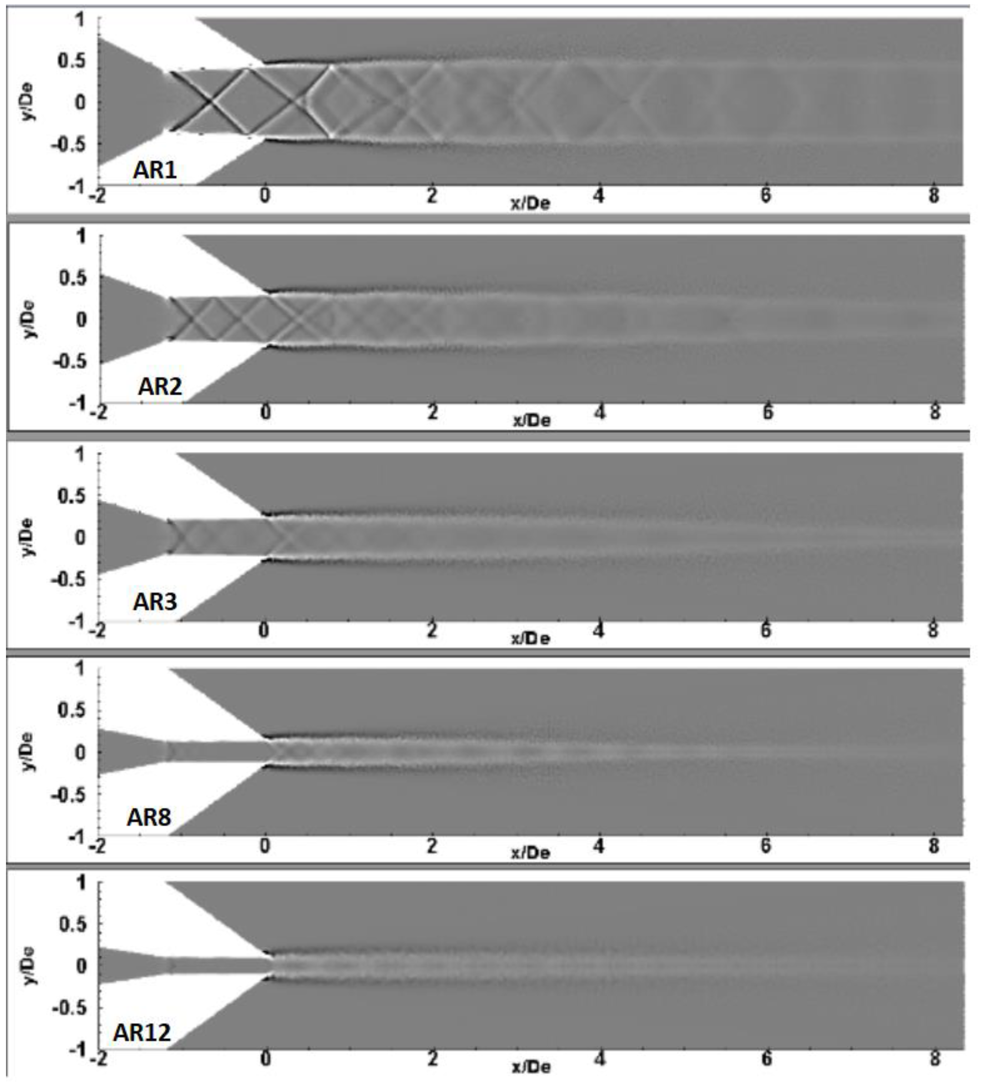
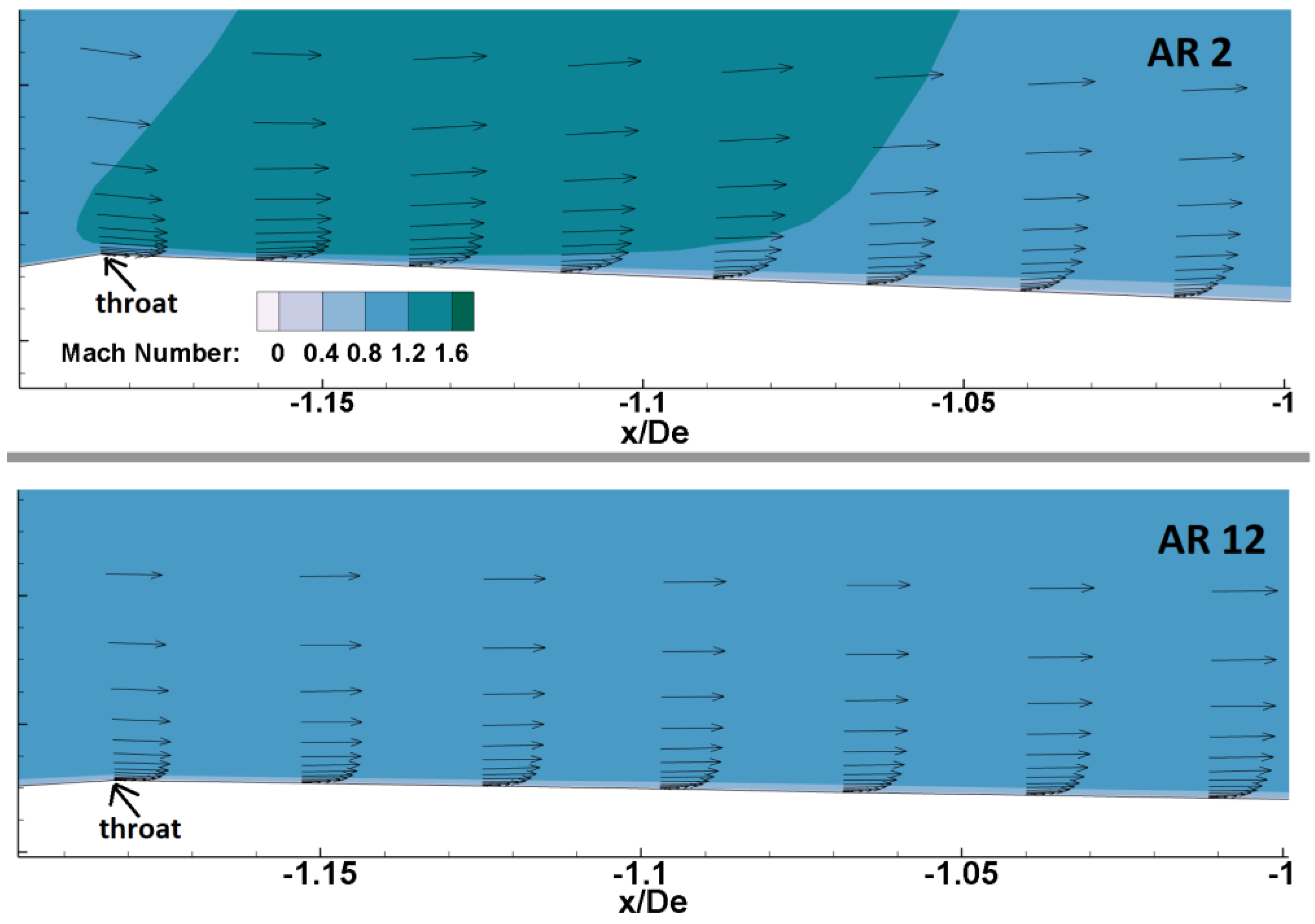
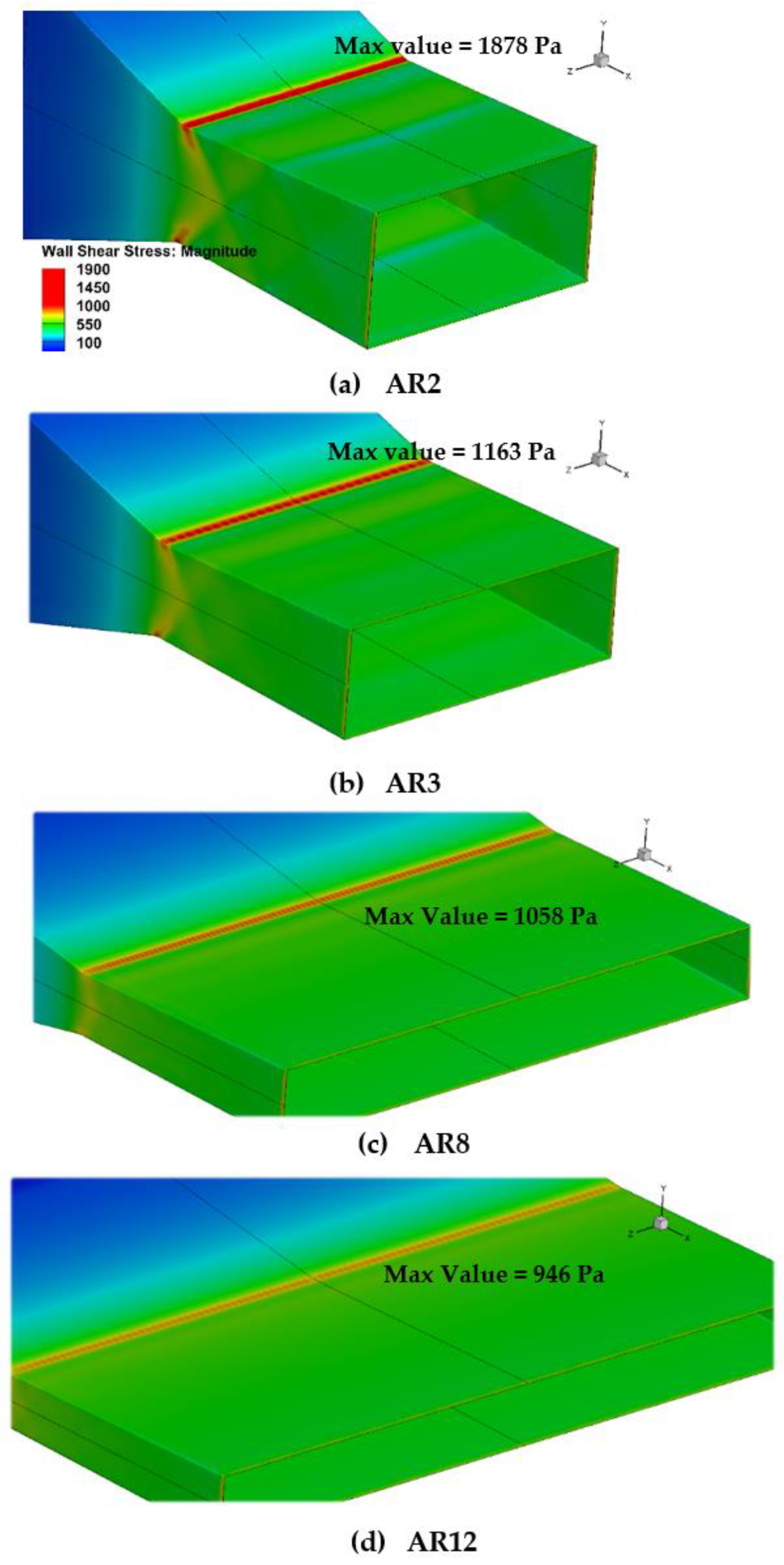
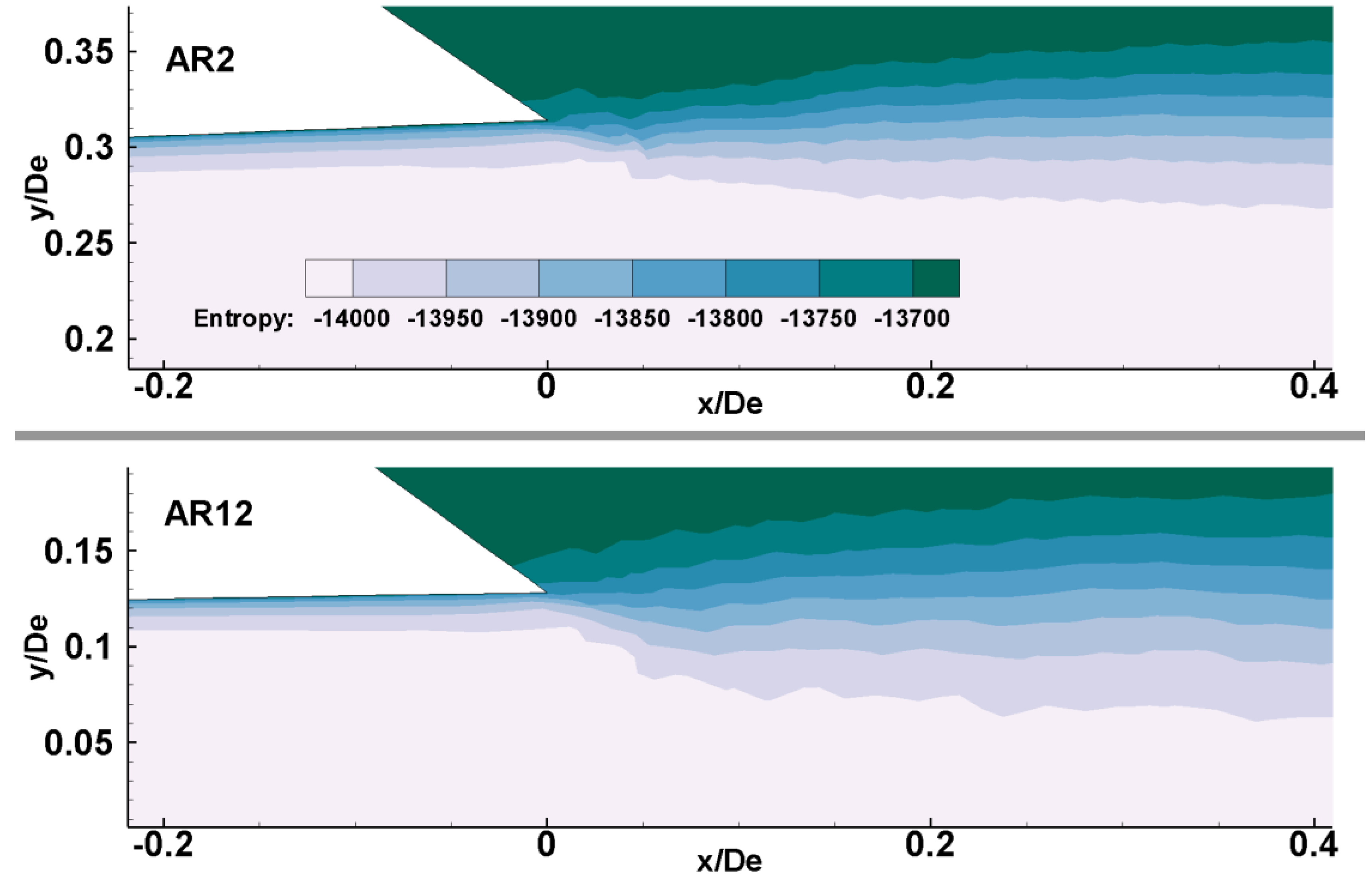
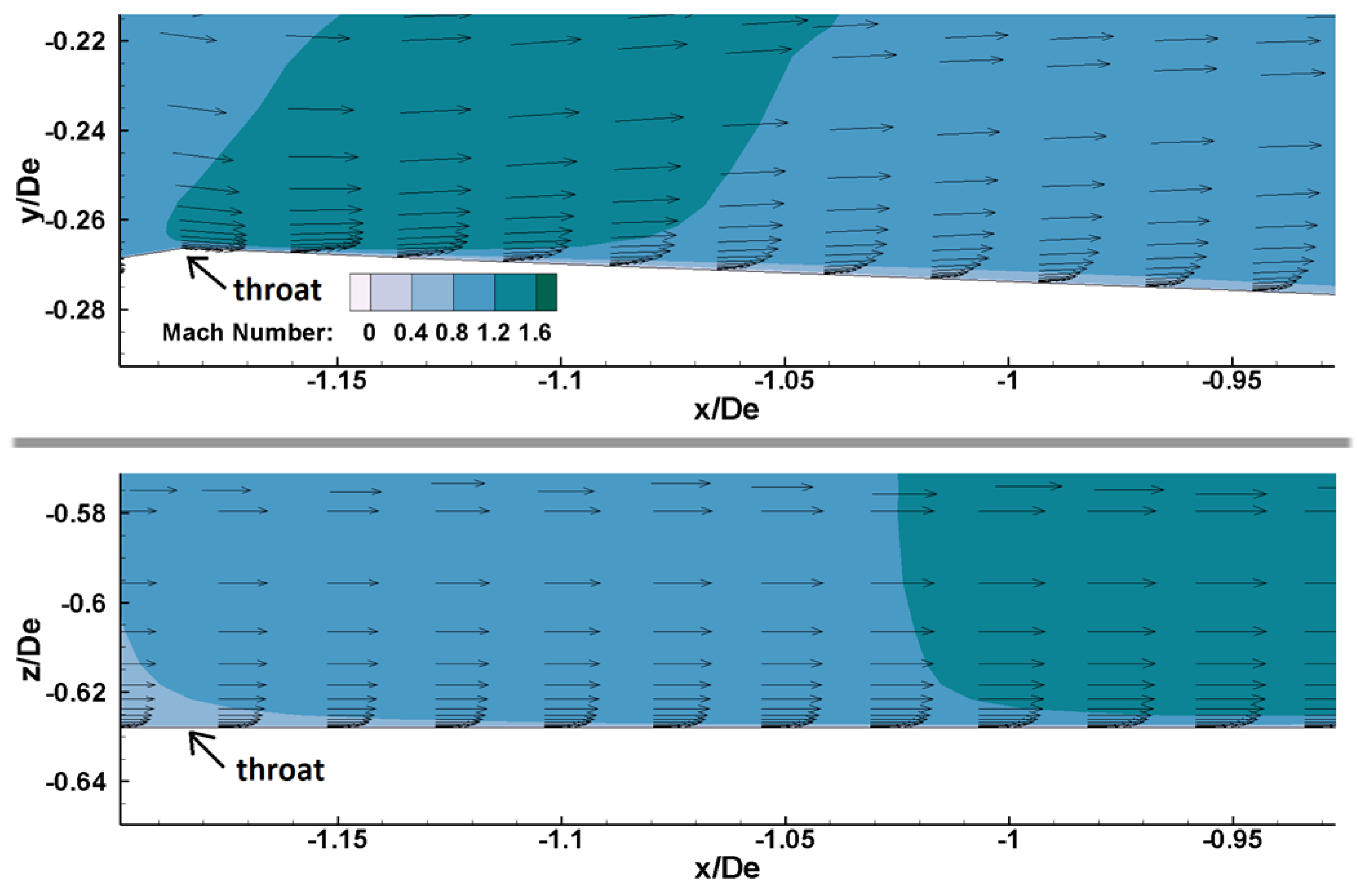
3.1. Aspect Ratio and Shock Formation

The focus of this subsection is to analyze the shock structure. Figure 3 shows the numerical shadowgraph on the XY symmetry plane for the five nozzle configurations indicating the shock propagation. Note that the scale of the shadowgraph contour plots is adjusted to compare all 5 nozzle geometries in one plot to help compare the low vs. high ARs. Shock cell size reduces with an increase in aspect ratio. This causes more shock reflections inside the nozzle. At high ARs, the shocks become milder as illustrated in Figure 3.
When the shock wave travels from the wall to the centerline, the boundary layer becomes thicker in the AR2 nozzle (Figure 4) due to the adverse pressure gradient imposed by an oblique shock wave. Comparing with the AR12 nozzle, the boundary layer from the throat onwards is thin since the shocks are not as severe.
A thicker boundary layer generates more aerodynamic blockage to the flow. Figure 5 shows that the discharge coefficient increases as the aspect ratio increases. The discharge coefficient is defined in Equation (6) and is an indicator of aerodynamic blockage to the flow on account of boundary layer formation, where a c t u a l   is the actual mass flow rate through the nozzle and i d e a l is calculated using isentropic relations. The higher its value, the thinner the boundary layer.
C d   =   a c t u a l i d e a l  
A thicker boundary layer creates more skin friction at the throat which results in higher magnitudes of wall shear stress at low ARs, as shown in Figure 6. This means that the velocity gradient in the boundary layer is larger at low ARs at the throat. At high ARs, the magnitudes of wall shear stress become smaller at the throat due to milder shocks.

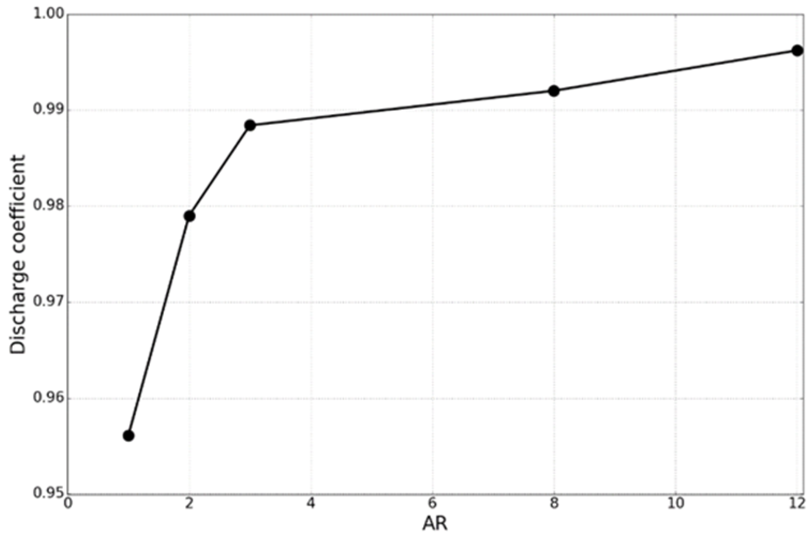
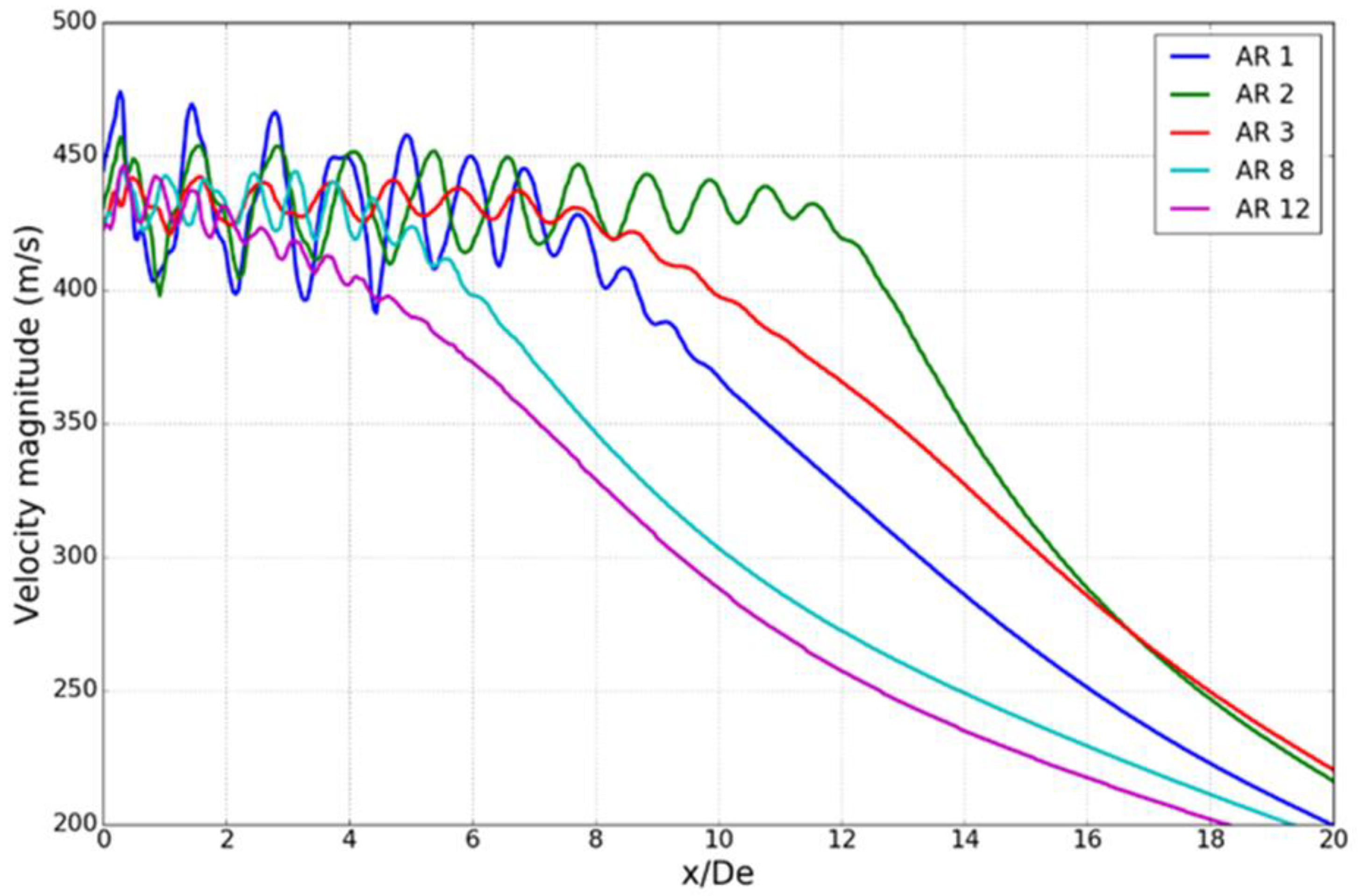
3.2. Nozzle-Exit Properties and Potential Core

Figure 7 shows the jet centerline velocity magnitudes for low to high values of AR indicating that the baseline nozzle has the highest potential core length while the AR12 nozzle has the smallest core length on account of better mixing and is illustrated in Figure 8 and Figure 9.
The boundary layer exiting the nozzle becomes a shear layer and can be visualized in Figure 8 for AR2 and AR12 nozzles. Figure 8 shows the entropy contour plots indicating the viscous dissipation through the boundary layer and shear layer. Note that the entropy in Star-CCM+ [25] is defined as in Equation (7), where C p is the specific heat in J/(kg·K), R is the specific gas constant in J/(kg·K), T is temperature in K and T r e f is the reference temperature, P is the absolute pressure in Pa and P r e f is the reference pressure. Star-CCM+ assumes the standard state temperature for an ideal gas as 298.15 K and standard state entropy as 0 [25]. Therefore, the entropy calculations are relative to the standard conditions and negative values are possible.
s = C p ln ( T T r e f ) R l n ( P P r e f )
A thicker shear layer in the AR12 nozzle (Figure 8) helps in jet mixing and the length of the potential core at high AR is smaller. Figure 9a shows the turbulent kinetic energy (TKE) contour plots for the AR2 and AR12 nozzles starting from the location just downstream of the nozzle exit. Figure 9b shows the entropy contour plots for both cases. The contour plots of TKE along with entropy show the losses due to viscous dissipation and accounts for jet mixing. This means that the nozzle AR influences the behavior of internal flow which eventually affects the jet mixing.

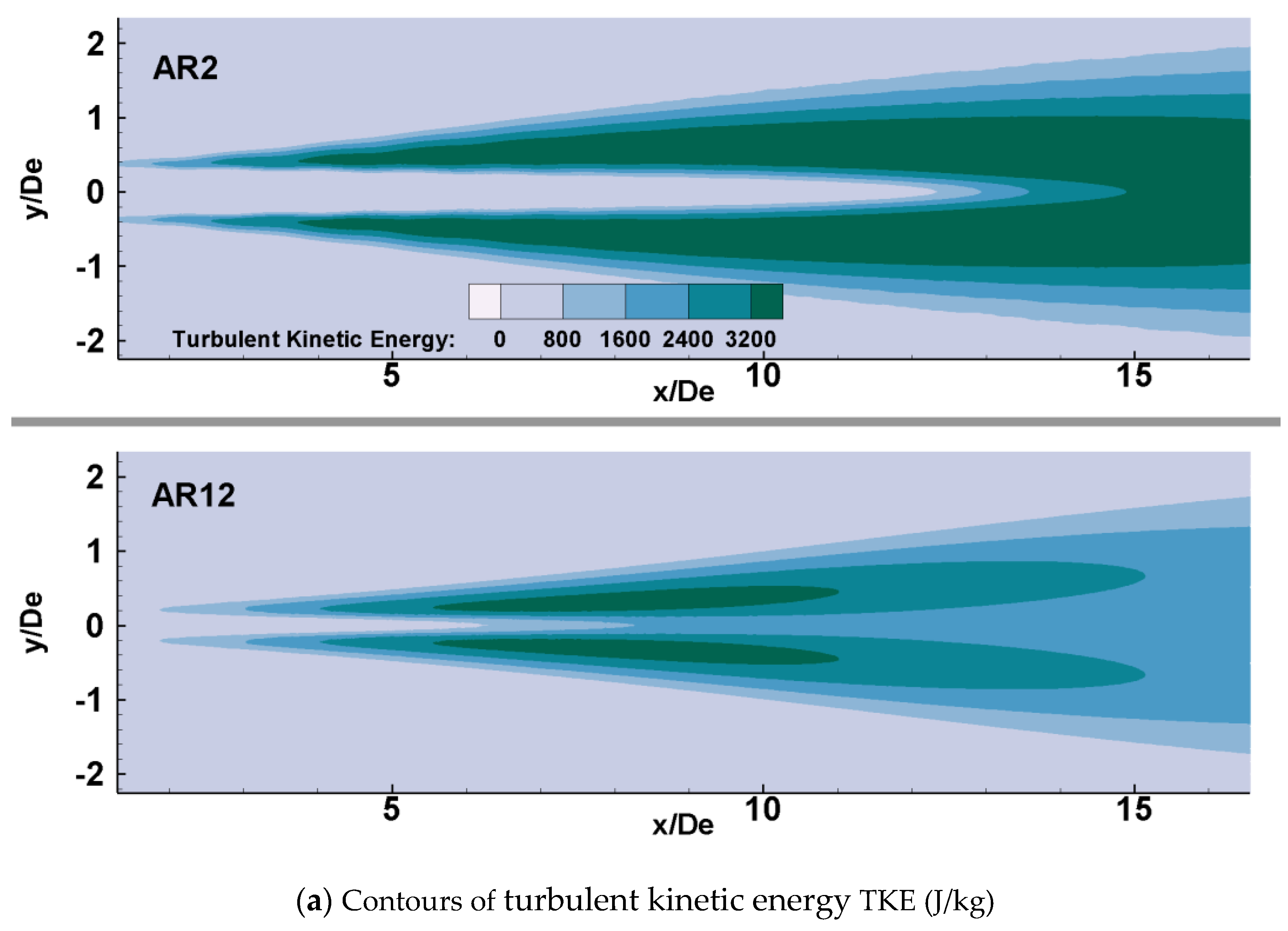
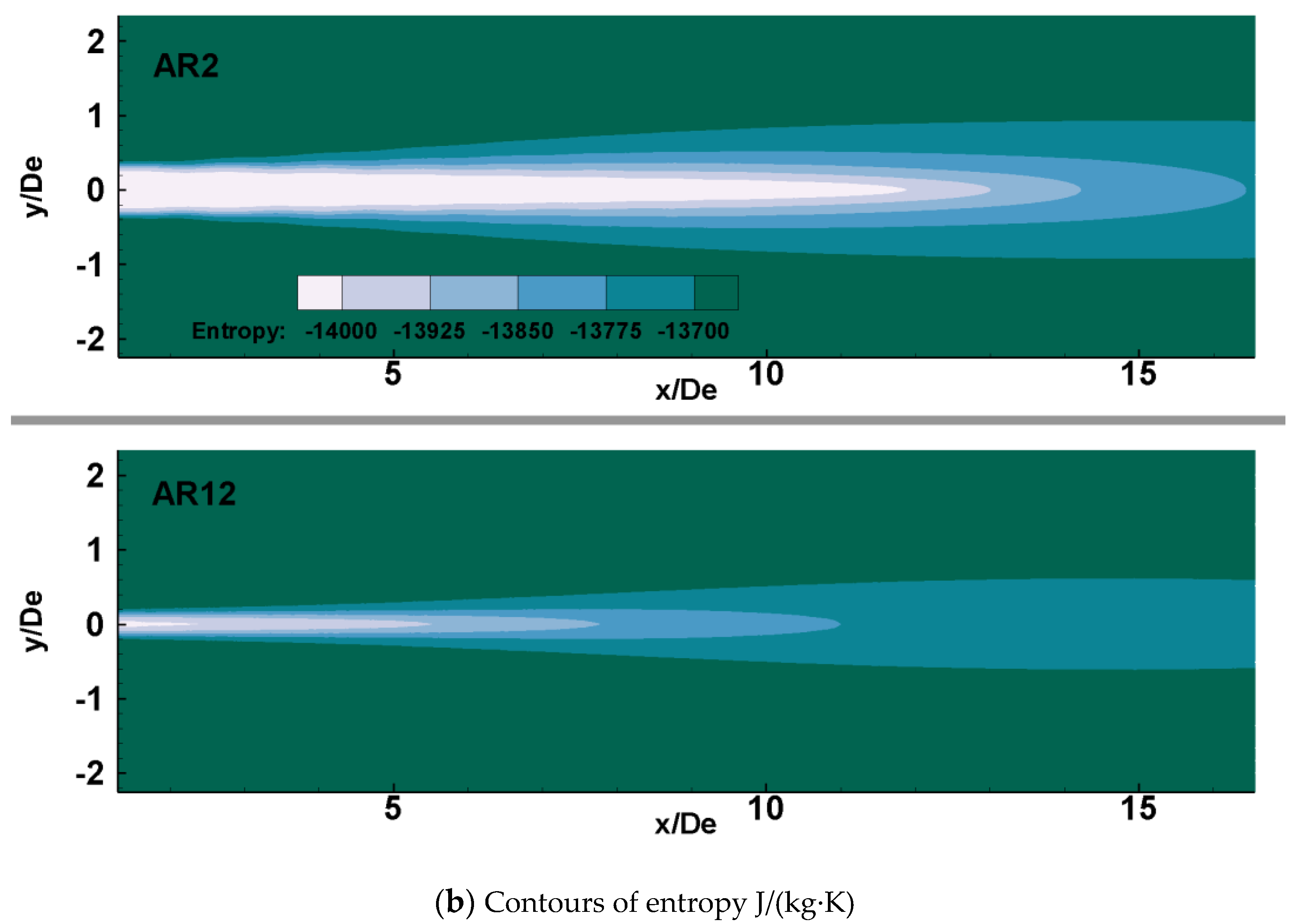
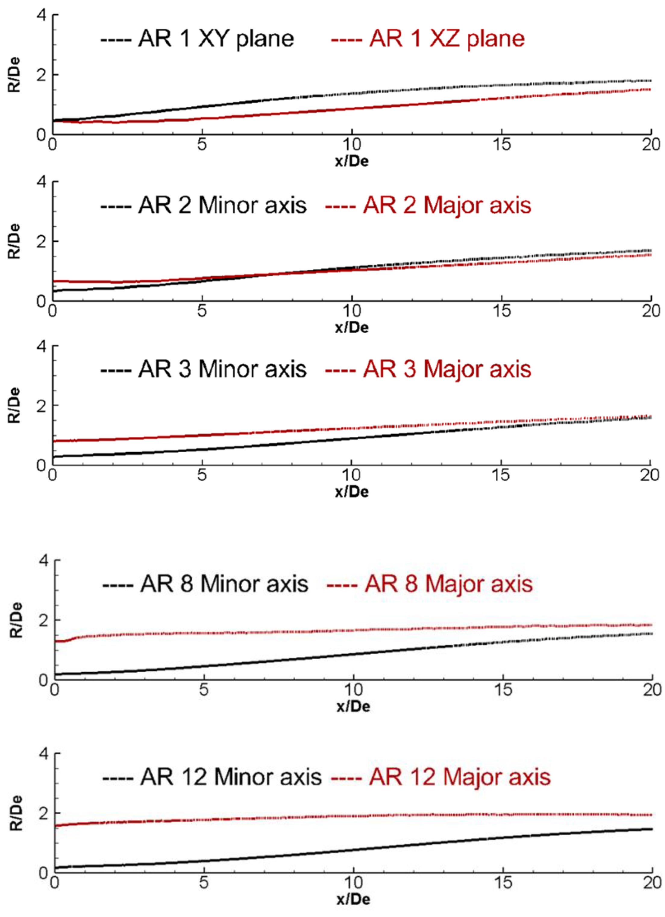
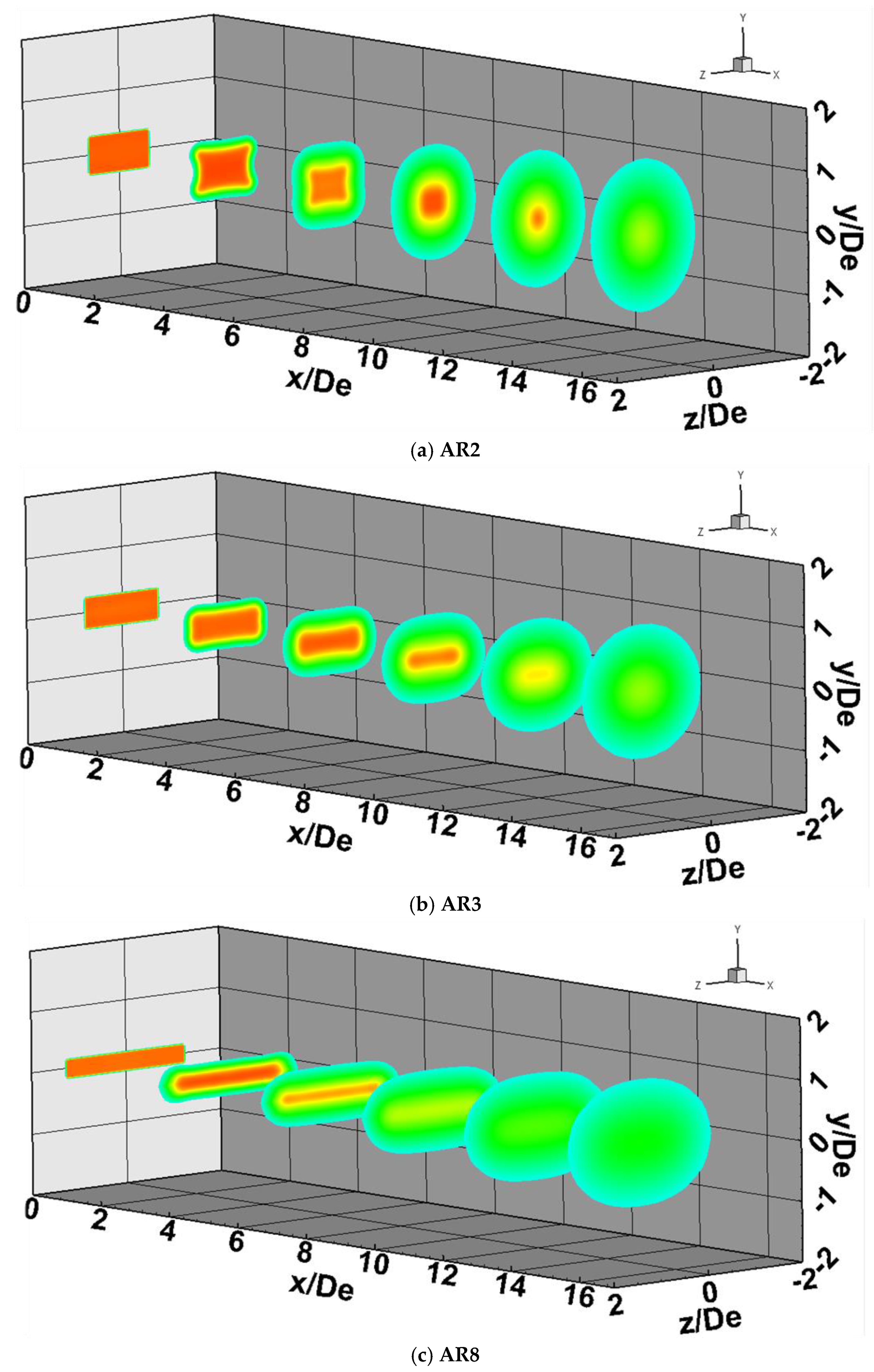
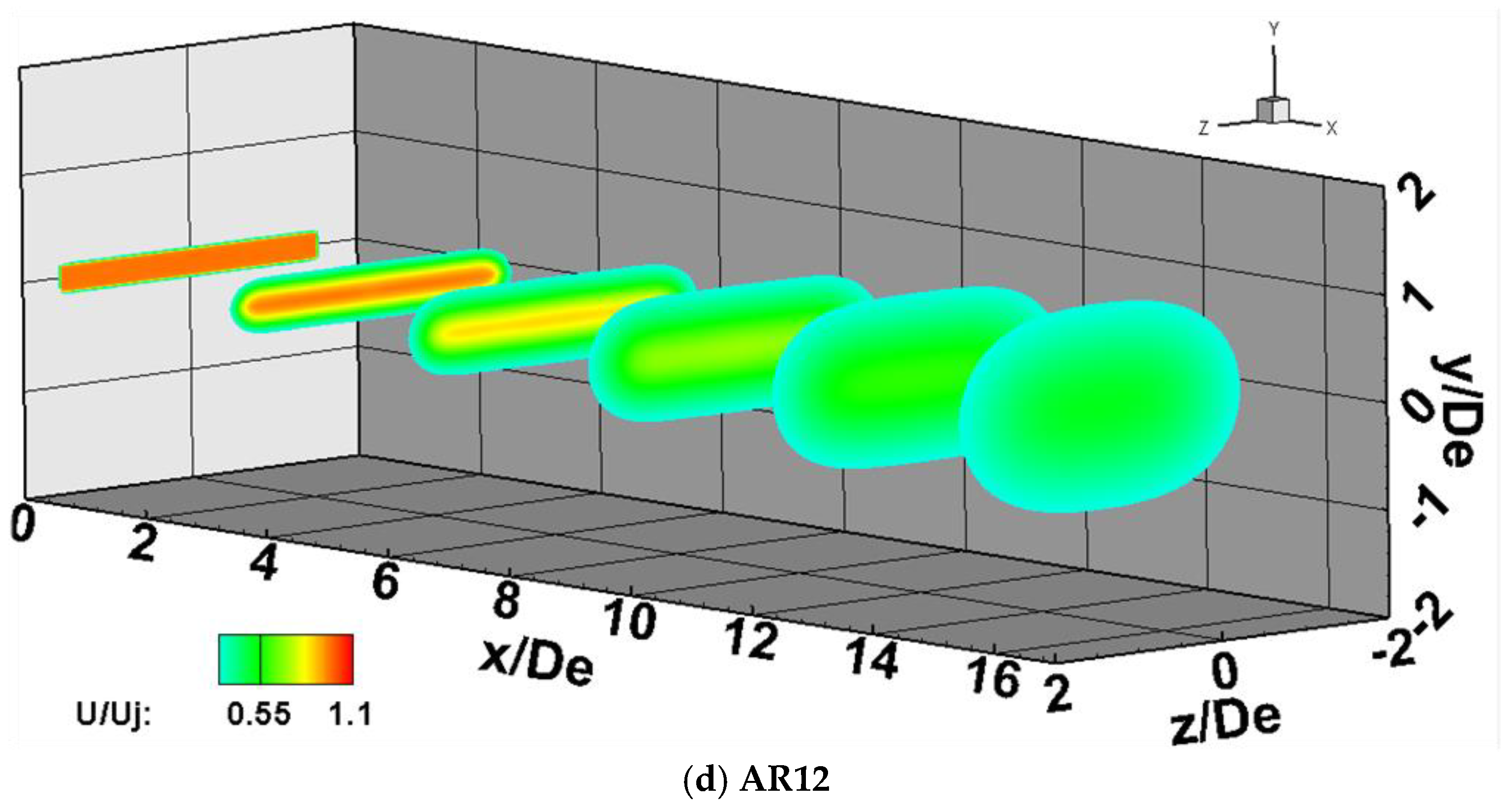
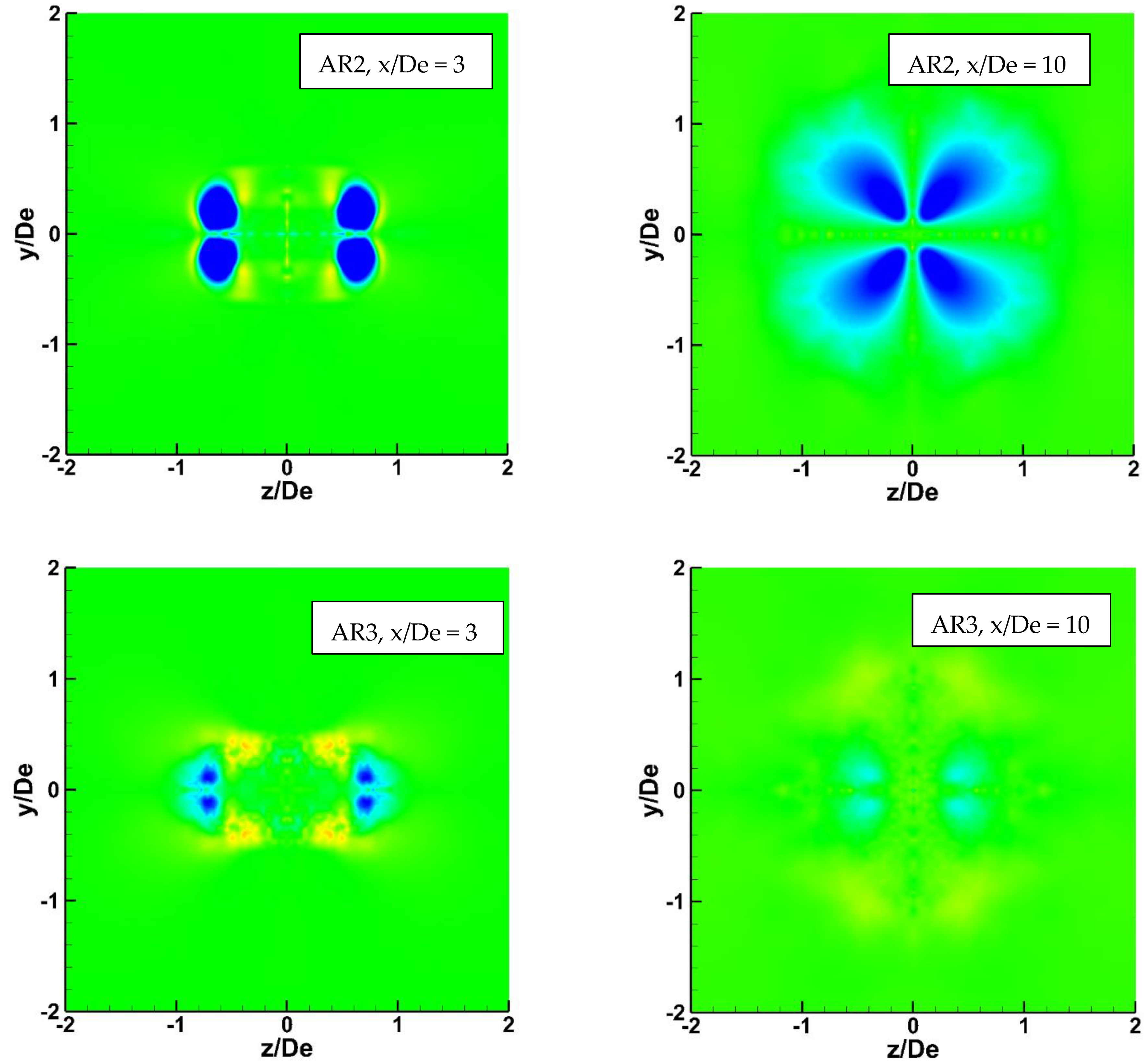
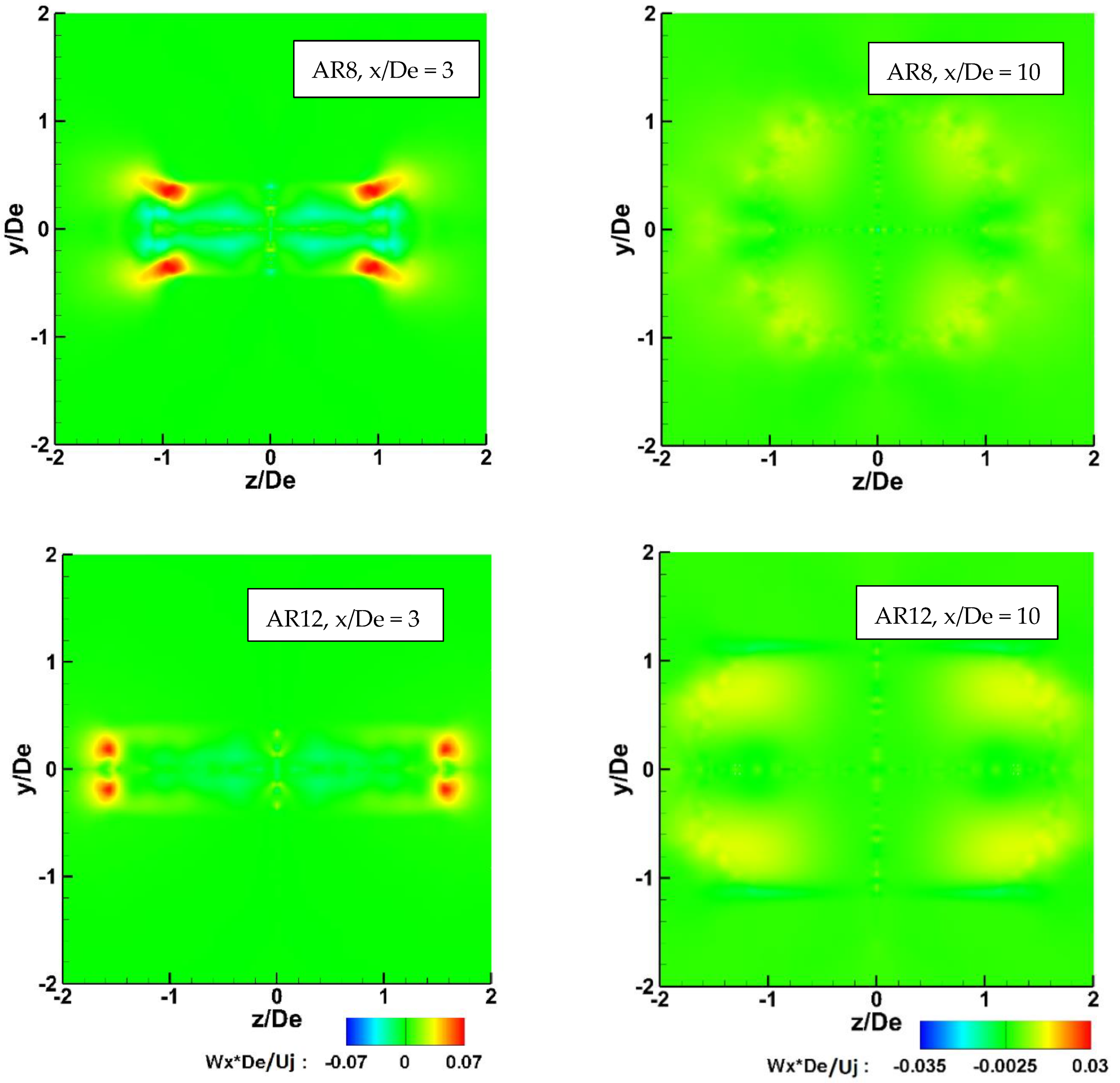
3.3. Jet Mixing, Axis Switching and Streamwise Vorticity

Axis switching is a phenomenon where the jet exiting an asymmetric nozzle evolves in such a way that the minor and major axes are interchanged [1]. Figure 10 shows the contours of Mach number = 0.3 on the minor and major axis symmetry planes. It is evident that the AR2 nozzle which is the baseline nozzle exhibits axis switching phenomenon at approximately 7–8 De downstream from the nozzle exit. AR3 nozzle exhibits axis switching at ~20 equivalent diameters downstream. As the AR increases, the axis switching phenomenon is delayed or virtually nonexistent. This is because the nozzle height decreases with increasing AR and the flow-turning at the throat from the converging to the diverging section decreases. This makes it difficult for the minor axis jet spread to match with the major axis jet spread. The AR1 nozzle, which is a square nozzle, shows an interesting jet spread. It shows a rapid jet spread on the XY plane due to the converging−diverging walls. The spread on the XZ plane is smaller because of the parallel walls. Note that the minor and major axis terminology is not used for AR1 nozzle since it is a square nozzle and is only as a reference.
Figure 11 illustrates a 3D perspective of contours of axial velocity (U) normalized by the jet centerline velocity at nozzle exit (Uj) along various X-planes, starting from nozzle exit at x/De = 0 to x/De = 15. The AR2 nozzle exhibits axis switching at around 7–8 De downstream (Figure 11a), therefore, the first three crossflow planes show a memory of the nozzle cross-section, but the last three crossflow planes show a circular shape of the contours. For the AR3 nozzle (Figure 11b), the minor and major axis spread becomes somewhat equal at ~20 x/De. The crossflow planes downstream the high AR nozzles exhibit an elliptical shape of the contours (Figure 11c,d). This means that the axis switching is delayed or virtually nonexistent in high AR cases.
The nozzle configurations have parallel walls in the major axis plane and converging−diverging walls in the minor axis plane. This causes the boundary layer to develop differently along both walls as illustrated in Figure 12. Figure 13 shows the normalized streamwise vorticity at x/De = 3 and x/De = 10 for various ARs. These locations are chosen because the plane closer to the nozzle exit (x/De = 3) still has a memory of the exit cross section as can be seen from Figure 11 and as one moves away from the exit, i.e., around x/De = 10, the memory becomes weaker, and the cross sections start to become either circular or elliptical depending on the AR.
The presence of corners at the nozzle exit and the difference in the growth of the boundary layer along the minor and major axis causes the generation of streamwise vorticity. The streamwise vorticity is normalized using De (nozzle exit equivalent diameter) and Uj (jet centerline velocity at nozzle exit corresponding to Mach number = 1.5). The vorticity magnitudes at x/De = 3 are higher and as one moves away from the nozzle-exit, i.e., at x/De = 10, the vorticity magnitudes become weaker as the kinetic energy of the jet starts to dissipate. It is challenging to visualize the direction of the vorticity fields due to such small magnitudes and not having the predominant components of the velocity vector in Y and Z directions. In both contour plots, the vorticity at AR = 2, 3, is negatively dominated while at AR = 8, 12, it is positively dominated. Note that since symmetry boundary conditions are used, the contour plots of vorticity are mirrored along the symmetry planes. The negatively dominated vorticity fields induce the flow into the jet stream causing a better jet spread in the minor axis which eventually helps in the axis switching phenomenon at AR = 2, 3. On the other hand, the positively dominated vorticity fields do not help the axis switching. This becomes evident from Figure 11 and Figure 13.

4. Conclusions and Future Work

The goal of this work was to assess the impact of AR on various factors such as the internal flow and the external flow features by understanding the shock formation, boundary layer growth and jet mixing characteristics. The relationship between the nozzle internal flow and external jet mixing is a result of boundary layer growth which is directly affected by nozzle aspect ratio. The severity of shock formation plays an important role in boundary layer development. While shock waves are present in all nozzle geometries due to the sharp throat, the shock strength and shock cell size decrease as the AR increases. Stronger shocks at low ARs cause the boundary layer to become thicker from throat onwards due to an adverse pressure gradient, however, at high ARs the boundary layers are thin due to weaker shock formation. A thin boundary layer offers less aerodynamic blockage to the flow and improves the discharge coefficient as the AR increases. The baseline nozzle (AR2) exhibits axis switching at ~7–8 equivalent diameters downstream of the exit and the AR3 nozzle exhibits axis switching at ~20 diameters downstream. As AR increases, axis switching is delayed or virtually nonexistent. The length of the potential core decreases as the AR increases on account of better mixing. Although the current scope was limited to cold flow conditions, it would be more realistic to investigate heated jets at higher temperature ratios. While it is possible to employ a nozzle with AR > 12, the primary question is what AR is feasible from the engineering standpoint for aircraft exhaust systems? This would be constrained by, and depend on, various factors, such as the aircraft aerodynamics, noise characteristics, and structural requirements as well as manufacturing and exhaust system integration constraints, and future work will address these factors.

Author Contributions

K.B. created the nozzle geometries, conducted the CFD simulations, analyzed the results and summarized the findings in this work. K.S. helped with the internal flow aerodynamics, qualitative analysis, and data representation. S.A. as the PhD advisor guiding with the research objectives and providing the computational resources. All authors have read and agreed to the published version of the manuscript.

Funding

This research received no funding.

Institutional Review Board Statement

Not applicable.

Informed Consent Statement

Not applicable.

Conflicts of Interest

The authors declare no conflict of interest.

Abbreviations

ARAspect ratio
CFDComputational fluid dynamics
LESLarge eddy simulation
RANSReynolds-averaged Navier−Stokes
RRadial distance
SSTShear stress transport
TKETurbulent kinetic energy
TRTemperature ratio
UVelocity in X direction
WVorticity

Nomenclature

AexitNozzle-exit area
CdDischarge coefficient
De Nozzle-exit equivalent diameter
UjJet velocity at nozzle exit
WxStreamwise vorticity
xStreamwise location in X direction
yLocation in Y direction
zLocation in Z direction

References

  1. Zaman, K.B.M.Q. Axis switching and spreading of an asymmetric jet: The role of coherent structure dynamics. J. Fluid Mech. 1996, 316, 1–27. [Google Scholar] [CrossRef]
  2. Zaman, K.B.M.Q. Spreading Characteristics and Thrust of Jets from Asymmetric Nozzles. In Proceedings of the 34th Aerospace Sciences Meeting and Exhibit, Reno, NV, USA, 15–18 January 1995; p. 200. [Google Scholar]
  3. Zaman, K.B.M.Q.; Steffen, C.J.; Reddy, D.R. Entrainment and Spreading Characteristics of Jets from Asymmetric Nozzles. In Proceedings of the 4th Shear Flow Conference, Snowmass Village, CO, USA, 29 June–2 July 1997. [Google Scholar]
  4. Gutmark, E.; Schadow, K.C.; Bicker, C.J. Near acoustic field and shock structure of rectangular supersonic jets. AIAA J. 1990, 28, 1163–1170. [Google Scholar] [CrossRef]
  5. Krothapalli, A.; Baganoff, D.; Karamcheti, K. On the mixing of a rectangular jet. J. Fluid Mech. 1981, 107, 201–220. [Google Scholar] [CrossRef]
  6. Mora, P. Investigation of the Noise Radiation from Heated Supersonic Jets. Ph.D. Thesis, University of Cincinnati, Cincinnati, OH, USA, 2016. [Google Scholar]
  7. Baier, F.; Mora, P.; Gutmark, E.; Kailasanath, K. Flow Measurements from a Supersonic Rectangular Nozzle Exhausting over a Flat Surface. In Proceedings of the 55th AIAA Aerospace Sciences Meeting, Grapevine, TX, USA, 9–13 January 2017. [Google Scholar]
  8. Brown, C.; Dippold, V. Jet-Surface Interaction–High Aspect Ratio Nozzle Test Nozzle Design and Preliminary Results. In Proceedings of the Acoustics Working Group Meeting, Cleveland, OH, USA, 20–21 October 2015. [Google Scholar]
  9. Viswanath, K.; Johnson, R.; Corrigan, A.; Kailasanath, K.; Mora, P.; Baier, F.; Gutmark, E. Noise Characteristics of a Rectangular vs. Circular Nozzle for Ideally Expanded Jet Flow. In Proceedings of the 54th AIAA Aerospace Sciences Meeting, San Diego, CA, USA, 4–8 January 2016. [Google Scholar]
  10. Munday, D.; Gutmark, E.; Liu, J.; Kailasanath, K. Flow Structure of Supersonic Jets from Conical Cd Nozzles. In Proceedings of the 39th AIAA Fluid Dynamics Conference, San Antonio, TX, USA, 22–25 June 2009. [Google Scholar]
  11. Fontaine, R.; Elliott, G.; Austin, J.; Freund, J. Very near-nozzle shear-layer turbulence and jet noise. J. Fluid Mech. 2015, 770, 27–51. [Google Scholar] [CrossRef]
  12. Heeb, N.; Mora, P.; Gutmark, E.; Kailasanath, K. Investigation of the Noise from a Rectangular Supersonic Jet. In Proceedings of the 19th AIAA/CEAS Aeroacoustics Conference, Berlin, Germany, 27–29 May 2013. [Google Scholar]
  13. Dippold, V., III. Design and Analyses of High Aspect Ratio Nozzles for Distributed Propulsion Acoustic Measurements. In Proceedings of the 34th AIAA Applied Aerodynamics Conference, Washington, DC, USA, 13–17 June 2016. [Google Scholar]
  14. Liu, J.; Kailasanath, K.; Ramamurti, R.; Munday, D.; Gutmark, E.; Lohner, R. Large-eddy simulations of a supersonic jet and its near-field acoustic properties. AIAA J. 2009, 47, 1849–1865. [Google Scholar] [CrossRef]
  15. Frate, F.; Bridges, J. Extensible Rectangular Nozzle Model System. In Proceedings of the 49th AIAA Aerospace Sciences Meeting including the New Horizons Forum and Aerospace Exposition, Orlando, FL, USA, 4–7 January 2011; p. 975. [Google Scholar]
  16. Behrouzi, P.; McGuirk, J. Underexpanded jet development from a rectangular nozzle with Aft-Deck. AIAA J. 2015, 53, 5. [Google Scholar] [CrossRef] [Green Version]
  17. Chen, N.; Huidan, Y. Mechanism of axis switching in low aspect-ratio rectangular jets. Int. J. Comput. Math. Appl. 2014, 67, 437–444. [Google Scholar] [CrossRef]
  18. Pereira, O.; Rodríguez, A.; Calleja-Ochoa, A.; Celaya, A.; Lopez de Lacalle, L.N.; Fernandez-Valdivielso, A.; Gonzalez, H. Simulation of cryo-cooling to improve super alloys cutting tools. Int. J. Precis. Eng. Manuf. Green Technol. 2021. [Google Scholar] [CrossRef]
  19. Trumper, M.; Behrouzi, P.; McGuirk, J. Influence of nozzle exit conditions on the near-field development of high subsonic and underexpanded axisymmetric jets. Aerospace 2018, 5, 35. [Google Scholar] [CrossRef] [Green Version]
  20. Georgiadis, N.J.; DeBonis, J. Navier–stokes analysis methods for turbulent jet flows with application to aircraft exhaust nozzles. Prog. Aerosp. Sci. 2006, 42, 377–418. [Google Scholar] [CrossRef]
  21. Bhide, K.; Siddappaji, K.; Abdallah, S. A Combined Effect of Wall Curvature and Aspect Ratio on the Performance of Rectangular Supersonic Nozzles. In Proceedings of the 6th International Conference on Jets, Wakes and Separated Flows, Cincinnati, OH, USA, 9–12 October 2017. [Google Scholar]
  22. Bhide, K.; Siddappaji, K.; Abdallah, S. Influence of fluid–thermal–structural interaction on boundary layer flow in rectangular supersonic nozzles. Aerospace 2018, 5, 33. [Google Scholar] [CrossRef] [Green Version]
  23. Bhide, K. On Shock-Boundary Layer Interactions-A Multiphysics Approach. Master’s Thesis, University of Cincinnati, Cincinnati, OH, USA, 2018. [Google Scholar]
  24. Greitzer, E.; Tan, C.; Graf, M. Internal Flow: Concepts and Applications; Cambridge University Press: Cambridge, UK, 2007; Volume 3. [Google Scholar]
  25. Star-CCM+ User Guide. Available online: https://docs.sw.siemens.com/documentation/external/PL20190509110447511/en-US/starccm/starccm/index.html#page/connect%2Fsplash.html (accessed on 28 February 2021).
Figure 1. Mesh and computational domain—(a) polyhedral mesh on minor and major axis symmetry planes for the baseline nozzle, (b) computational domain.
Aerospace 08 00078 g001aAerospace 08 00078 g001b
Figure 2. Baseline nozzle geometry adapted from reference [9], dimensions in mm.
Aerospace 08 00078 g002
Figure 3. Numerical shadowgraph illustrating the shock propagation on minor axis symmetry plane for AR = 1, 2, 3, 8, 12.
Aerospace 08 00078 g003
Figure 4. Boundary layer growth from the throat to downstream in AR2 and AR12 nozzle on minor axis symmetry plane.
Aerospace 08 00078 g004
Figure 5. AR vs. discharge coefficient.
Aerospace 08 00078 g005
Figure 6. Contours of wall shear stress (Pa) zoomed in at the nozzle throat (a) AR2, (b) AR3, (c) AR8, (d) AR12 (the contour plot range is adjusted for better visualization).
Aerospace 08 00078 g006
Figure 7. Jet centerline velocity downstream the nozzle exit.
Aerospace 08 00078 g007
Figure 8. Contours of entropy J/(kg·K) zoomed in at nozzle exit in AR2 and AR12 nozzle on minor axis symmetry plane.
Aerospace 08 00078 g008
Figure 9. (a) Contours of TKE (J/kg), (b) contours of entropy J/(kg·K) downstream from the nozzle exit for the AR2 and AR12 nozzles on the minor axis symmetry plane.
Aerospace 08 00078 g009aAerospace 08 00078 g009b
Figure 10. Contours of Mach number = 0.3, indicating minor and major axis jet spread.
Aerospace 08 00078 g010
Figure 11. Contours of U/Uj starting from x/De = 0 (nozzle exit plane) to x/De = 3,6,9,12,15 for (a) AR2, (b) AR3, (c) AR8, (d) AR12.
Aerospace 08 00078 g011aAerospace 08 00078 g011b
Figure 12. Growth of boundary layer along minor axis symmetry (top) and major axis symmetry (bottom) in the AR2 nozzle.
Aerospace 08 00078 g012
Figure 13. Normalized streamwise vorticity contours at x/De = 3 (left), x/De = 10 (right)—AR = 2, 3, 8, 12 from top to bottom.
Aerospace 08 00078 g013aAerospace 08 00078 g013b
Table 1. Computational fluid dynamics (CFD) case abbreviations.
Aspect RatioAbbreviation
1AR1
2AR2
3AR3
8AR8
12AR12
Publisher’s Note: MDPI stays neutral with regard to jurisdictional claims in published maps and institutional affiliations.

