Article

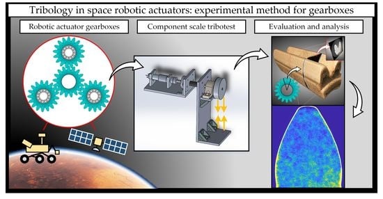
Tribology in Space Robotic Actuators: Experimental Method for Evaluation and Analysis of Gearboxes

Department of Engineering Sciences and Mathematics, Division of Machine Elements, Luleå University of Technology, SE-97187 Luleå, Sweden
*
Author to whom correspondence should be addressed.
Aerospace 2021, 8(3), 75; https://doi.org/10.3390/aerospace8030075
Submission received: 31 January 2021 / Revised: 3 March 2021 / Accepted: 10 March 2021 / Published: 13 March 2021
(This article belongs to the Special Issue Adaptive/Smart Structures and Multifunctional Materials in Aerospace)

Abstract

:
Liquid lubricants are critical to enable long-life operation of high-performance machinery, such as geared actuators employed in robotics. In space applications, actuator gearboxes must operate in low temperatures, where liquid lubricants face inherent problems related to low temperature rheology. Heaters are relied upon to provide acceptable gearbox temperatures. Unfortunately, heating is energy-intense and does not scale well with increasing mechanism mass and performance. Effective boundary lubrication (BL), on the other hand, can minimize problems of low temperature rheology. BL relies on tribofilm formation over conventional fluid film separation. Effective space grade boundary lubricants can potentially allow for drastically reduced amounts of oil and the accompanying rheological problems. In this work, we describe the design of a methodology to evaluate and analyze tribology of actuator gearboxes operated under cryogenic oil-starved conditions in N2 atmosphere. The devised methodology enables research pertinent to space actuator tribology by accelerated testing and advanced analysis, as demonstrated by a lubricant candidate case study. Complementary microscopy techniques are discussed, and a novel methodology devised for gear internal microstructure analysis by X-ray microtomography (XMT) is presented.

Graphical Abstract

1. Introduction

Past, current, and future space exploration—whether conducted remotely, autonomously, or crewed—rely heavily on robotics [1,2,3,4]. Geared actuators are critical robotic subsystems that provide accurate, efficient, and reliable rotary motion that enables mobility of the robot. The dominant type of geared actuators employed in space robotics consist of an electric motor coupled to a multistage geared transmission [5,6,7]. On Earth, fluid lubrication (oil or grease) is commonly employed to ensure acceptable performance in terms of tribology (friction and wear) in geared transmissions. While liquid lubricants are preferred also in space applications, the constraints of the environment leave only a limited choice of liquid lubricants available, and the tribological performance of these lubricants with space heritage is not yet on par with their terrestrial counterparts [8,9]. Liquid lubricants, such as perfluoroalkyl polyethers (PFPE) or multiply alkylated cyclopentanes (MAC) have been successfully employed since the initial lunar rover [10] and are still to this day [11]; however, they depend—and have always depended—on heaters and auxiliary systems to provide an acceptable operating environment for the lubricants.
Space tribology is becoming increasingly important [12]. The operating conditions faced by mechanisms in lunar or Martian mobility systems will become radically more severe, as recently pointed out by the NASA Office of the Chief Technologist [13]. As an example, current rover traverse speeds and ranges are in the order of 0.1 km/h and tenths of km over the life of the system. Crewed surface transport, on the other hand, will obviously require order-of-magnitude improvements in this regard, and, consequently, the topics of lubricants or lubrication systems are listed as critical technology for future space exploration [14].
Fundamental research efforts are ongoing to improve space-grade lubricants [15,16,17,18,19,20,21], materials [22,23], or lubrication systems [24]. Both fundamental and applied research is required. Model-scale laboratory screening studies under idealized conditions—such as the common ball-on-disc tribotest—is not sufficient for predicting tribology performance in complex mechanisms. One promising approach is the combination of extensive tribotesting in the model scale [21,25] with component level experiments [26,27]. Such an approach could be augmented by modelling and statistics in line with a lab-to-field upscaling concept [28]. For this purpose, tailor-made component level test rigs are required. Ideally, the complexity of such test rigs should be reduced as much as possible, while still replicating essential features of the field system.
In this work, we describe the design of a geared actuator test rig (GATR) and a detailed experimental methodology for tribology research pertinent to lubricated powder metal gears, such as those applied in space tribology. We specifically describe testing under oil-starved conditions, and we demonstrate the capability of the methodology by a case study that evaluates the influence on gear tribology by two space-grade lubricants. Further results have recently been published using this methodology [26]. The lubricant influence on relative energy efficiency of the geared actuators was measured in the GATR by comparing electrical power input to mechanical power output. After testing, we confirm the validity of the oil starvation methodology and describe a surface analysis procedure for inspecting the gears by a set of complementary techniques; the case study analysis include 3D-profilometry (3DP) combined with scanning electron microscopy (SEM), and the gear interior was analyzed by a novel methodology employing X-ray microtomography (XMT) combined with an edge-detection algorithm.

2. Materials and Methods

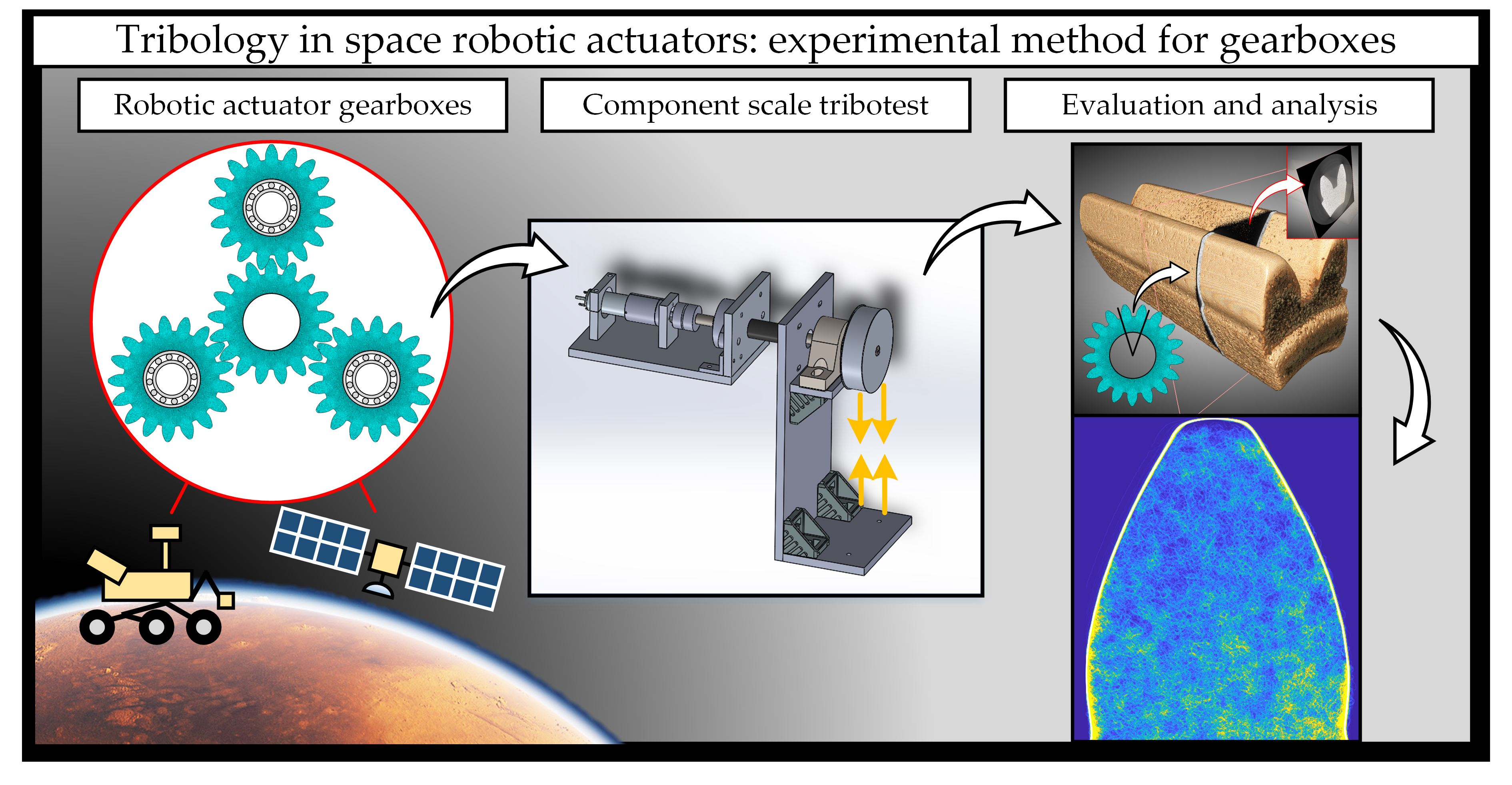
2.1. Design and Development of Geared Actuator Test Rig

A geared actuator test rig (GATR) was designed in order to evaluate the influence of tribological parameters (operating conditions, lubricants, materials) on gearbox tribological performance. The main purpose of the GATR is to provide a means of investigating the correlation between model scale and component scale tribotesting in tribosystems relevant to space tribology. Additionally, testing under component scale conditions provide important information about the damage modes of various interfaces, so that these interfaces can then be investigated in detail under model scale conditions. The GATR is intended as a component scale tribology test rig. The test environment roughly corresponded to a technology readiness level (TRL) between 4 and 5; however, the purpose of the experiments are experimental investigations under accelerated conditions and not component performance validation. This prototype test rig is also expected to provide information about the most important design features to include in the design of a higher TRL level component scale test rig, such as a device operating under thermal vacuum.
An overview of the geared actuator test rig (GATR) concept is shown in Figure 1, and details of salient features are discussed in the following sections. In this design, the geared actuator—including encoder, DC-motor, and the gearbox that is to be evaluated—is installed in a simple atmospheric chamber within a refrigerated compartment. The output shaft of the actuator gearbox is connected via a flexible shaft coupling to the output shaft where a dynamometer is installed. The design allows for exchanging actuator gearboxes or entire actuators. A simple control and instrumentation system was devised based on an open-source microcontroller, combined with a separate motor controller used for the closed-loop regulation of the DC-motor. A simple dynamometer was devised by employing a manually adjustable band brake with instrumentation to retrieve torque and speed.

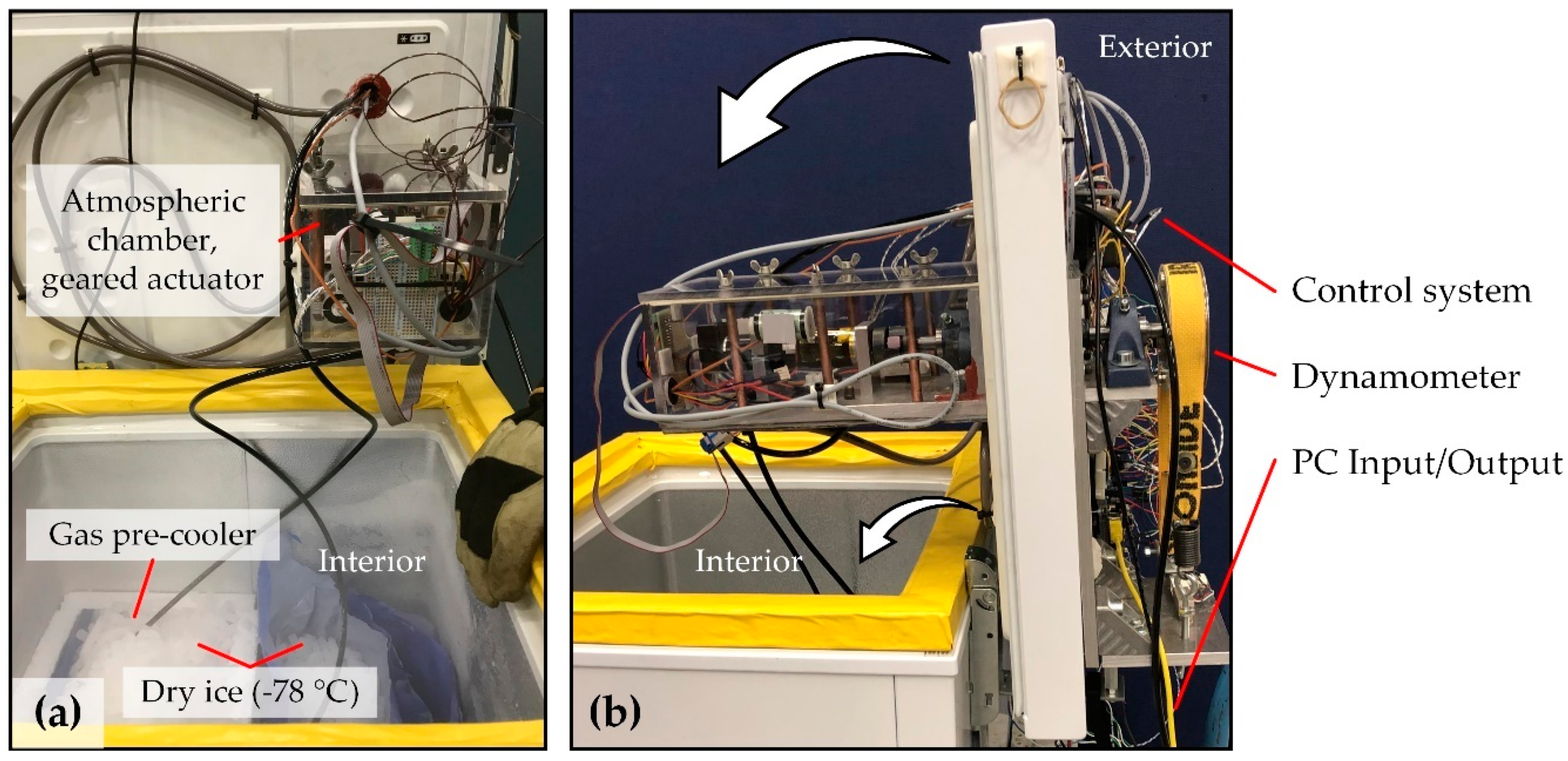
2.1.1. Atmospheric Chamber of GATR

The interior compartment is refrigerated by a conventional Joule–Thomson type heat exchanger found in commercially available refrigerators. The nominal minimum temperature of the refrigerator is −25 °C; however, augmented refrigeration by dry ice can be employed to maintain atmospheric chamber temperatures down to −78 °C. The atmospheric chamber can be flooded with nitrogen gas to mimic the vacuum environment, where hypoxic conditions are encountered in space applications. Optionally, the chamber can be flooded with a different gas, such as carbon dioxide, for investigating effects relevant to a Mars atmosphere [29]. Before entering the atmospheric chamber, the gas is passed through a precooler to ensure that the low temperature in the chamber is maintained. The chamber was sealed by use of membrane-type cable feedthroughs and a rotary seal at the output shaft; however, a low flow rate (< 0.1 L/min) was required to maintain an oxygen-free environment.

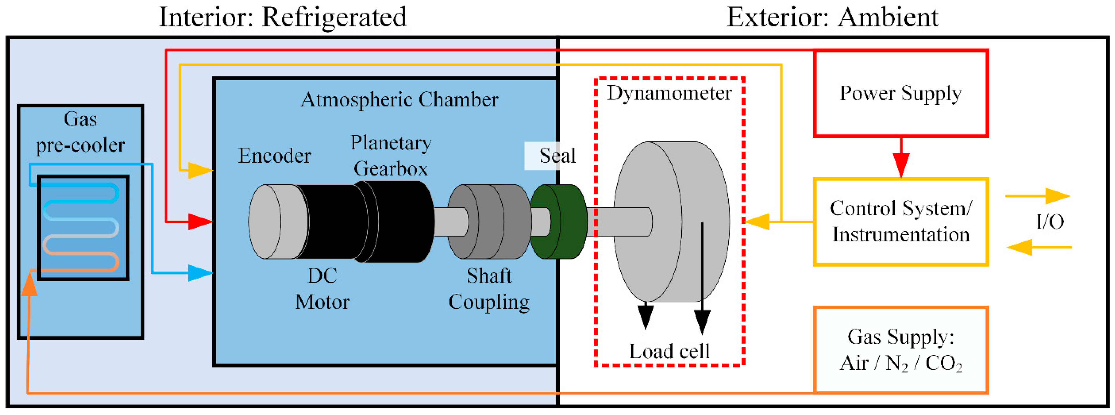
2.1.2. Actuator Gearbox

The GATR is designed for tribological evaluation of gearbox interfaces, and the GATR employs commercially available gearboxes. Geared actuators of different dimensions can be installed by use of different adaptors, and housing outer diameters between 22 and 36 mm can be accommodated. The baseline design uses a 60 w 24 V RE30 DC-motor in combination with a 51:1 gear ratio GP32A gearbox, both supplied from maxon (maxon motor ag, Sachseln, Switzerland). These geared actuators are well suited to tribological analysis, as they are manufactured to high quality tolerances and are relatively easy to disassemble and reassemble, as shown in Figure 2a. Similar geared actuators are employed in space missions, such as the recent Mars 2020 mission by NASA [30], where operations under starved conditions have received a lot of research interest, lately [27,31].
In order to evaluate the tribological performance and to facilitate comparisons to model scale experiments, it is important to understand the operating conditions in the gearbox. The GP32A unit is a three-stage planetary gearbox, with each gear stage consisting of a sun gear (pinion) that drives three planetary gears that are mounted on planet carrier shafts via integrated sleeve bearings. The gears—including their integrated journal bearings, referred to as sleeves—are manufactured from steel by a powder metal process, and the planet carrier shafts are machined from solid steel. In tribology, powder metallurgy is commonly applied to produce sintered sleeve bearings, where the porosity has the benefit of acting as lubricant reservoirs; however, a porous material also provides an increased number of sites where cracks can be initiated, and surface pores may inhibit hydrodynamic pressure. Although studies are emerging on powder metal gear material under model scale tribology experiments [32], there is little published data available on the use of powder metallurgical manufactured gears [33,34].
As shown in Figure 2, this type of gearbox has numerous tribological interfaces that needs to be lubricated. The area of lubricated interfaces is an important parameter when considering the risk of lubricant failure. In Figure 2b, three examples of areas are shown: a gear tooth flank surface, the front that interfaces to the separator disc, and the sleeve that interfaces to the carrier shaft. The total area to be lubricated in gear stage 3 is approximately 2500 mm2.
The various interfaces operate under different conditions in terms of sliding speed, contact pressure, temperature, etc., which means that the lubricant must be effective under an extremely wide range of conditions. The gear reduction of 51:1 (exactly 17576/343) means that the output carrier operates at 51 times the torque, and 1/51 times the speed, in comparison to the input motor pinion. Consequently, the input stage will encounter the most number of cycles, while the output stage will encounter the highest torque. The input stage is likely to have a more favorable state of lubrication, as high speeds promote hydrodynamic fluid pressure so that a lubricant film can be generated in the contact. Apart from the speed and torque differences between the gear stages, each gear stage also contains a number of tribological interfaces that operate under completely different conditions. In Figure 2b, three distinct planet gear contact surfaces are shown. The tooth actually has two different contacts, as one side is driven by the sun gear from the previous stage, and the other side of the tooth is driving against the ring gear. The gears are subjected to rolling–sliding conditions, under contact stress (pressure) around the 109 Pa order of magnitude (GPa). The sleeve bearing, on the other hand, is operating under pure sliding, at moderate contact pressures around 106 Pa (MPa). Finally, the front side of the gear is sliding in contact against the separator disk, and the back side against the planet carrier assembly. In contrast to the sleeve bearings, the front and back sliding contacts do not have any converging gap that can generate hydrodynamic pressure. On the other hand, the contact pressures are very mild, as there are no axial loads in nominal conditions. Apart from the gear interfaces discussed, there are also integrated roller bearings (not shown) in both the DC motor and the gearbox housing output. In summary, there are numerous tribological interfaces in a multistage planetary gearbox, and these interfaces are subjected to a very wide range of operating conditions.

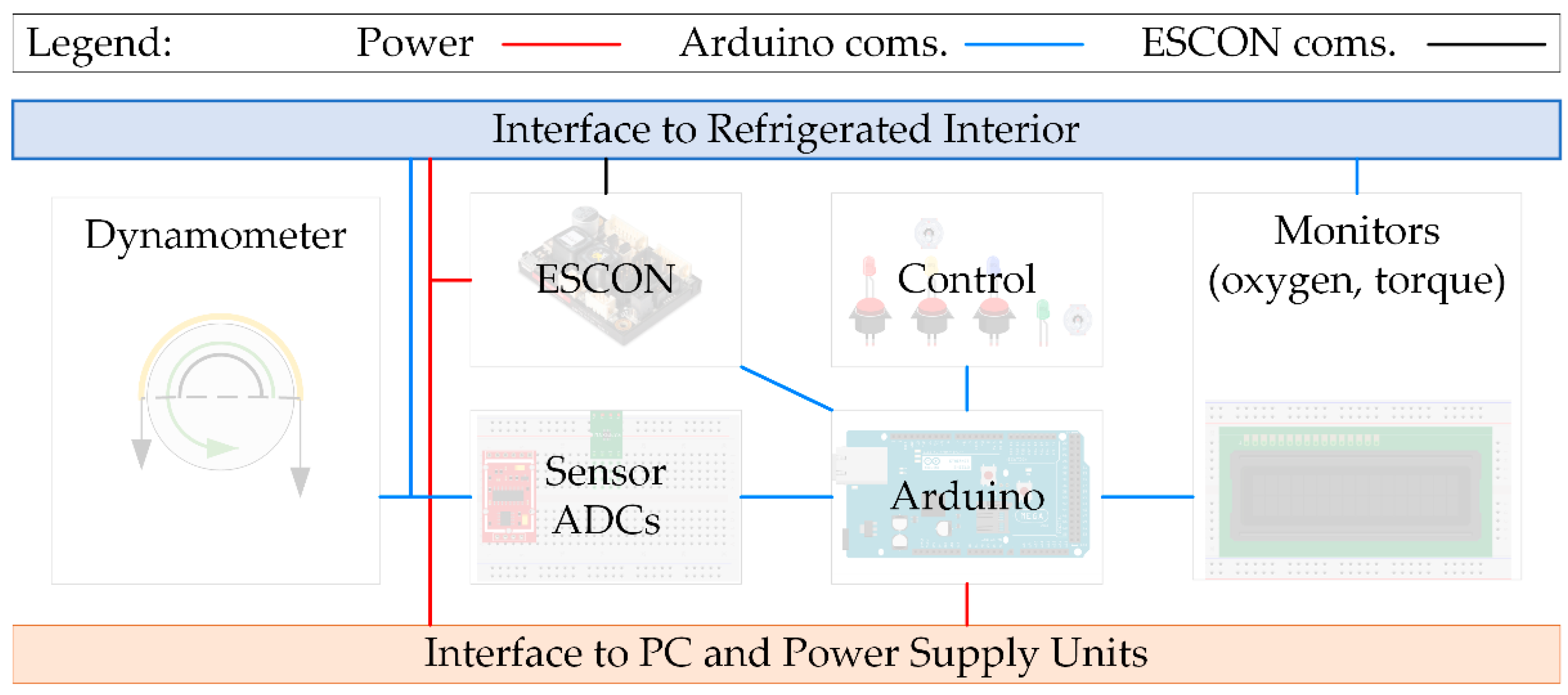
2.1.3. Control System, Data Acquisition, and Instrumentation

Two microcontrollers are employed for control and data acquisition: an Arduino Mega serves as the main microcontroller, while an ESCON servo controller is employed for accurate motor control and encoder communication. The details of the controllers and all instrumentation employed is found in Table 1, and an overview of the electronics system layout is provided in Figure 3. Both controllers are mounted on the exterior of the test rig and are connected to sensors within the refrigerated interior via an interface with a sealed cable feedthrough.
The ESCON communicates with the motor encoder (maxon HEDL 5540) to provide motor control in a closed loop, PID-regulated, pulse width modulation (PWM)-scheme (configured using the software ESCON studio). The ESCON controller communicates encoder data to the Arduino for logging at 10 Hz and receives motor speed set points from the Arduino Mega based on predefined test schemes. Optionally, the ESCON can be connected to a PC by USB to directly retrieve the high frequency data. Arduino data is stored using the SD card or directly retrieved via USB connection to a PC. All electronics are powered using two RND-320-KD3305P bench top power supply units (PSUs). The PSUs provide a total of four channels at 30 V 5 A, as well as two signal channels (5 V). The limiting factor for motor current supply is the ESCON 36/2, which is rated at max 2 ampere continuous current, with peak capacity of 4 A.
The exterior sensors refer to the sensors required to retrieve the mechanical output power produced at the band brake. A simple dynamometer was designed by employing a digital Hall-effect sensor (SS441A, Honeywell International Inc., Charlotte, NC, USA) that measures the rotational speed of a magnet attached to the output disc of the band brake, together with a load cell (TAL220) that measures the tension in the band of the band brake. The Hall-effect sensor is mostly redundant, since the motor encoder provides accurate speed data at the input (motor). With the fixed speed coupling, the Hall-effect sensor should produce a speed measurement that is inversely proportional to the gear ratio when compared to the motor encoder speed. The Hall-effect sensor can, thereby, provide a means of redundancy, ensuring that any slip or seizure in the transmission is detected so that the test can be immediately stopped. The load cell was used in connection with an amplifier (HX711), which was calibrated in increments of 5 N by applying known weights within the measuring range of 0–10 kg force.
The interior sensors refer to the sensors connected to the geared actuator or within the atmospheric chamber. The most important sensor is the motor encoder (HEDL 5540), which provides accurate rotational speed and input current of the DC-motor. Those parameters are necessary for the closed loop PWM control of the DC-motor but also to calculate the efficiency of the geared actuator. The encoder data is passed to the ESCON, which communicates to the Arduino Mega for logging the data. Apart from the encoder, salient interior sensors include the temperature and humidity sensor (type DHT22), that measure the ambient conditions inside the atmospheric chamber, and the thermocouples attached to the gearbox housing. The GATR baseline design uses a single type-K thermocouple attached to the gearbox housing; however, additional thermocouples can be employed at the expense of reduced data acquisition frequency. Finally, the oxygen detector is attached when testing under N2 conditions. An overview of the electronic control system and instrumentation layout is shown in Figure 3, and key specifications are listed in Table 1.

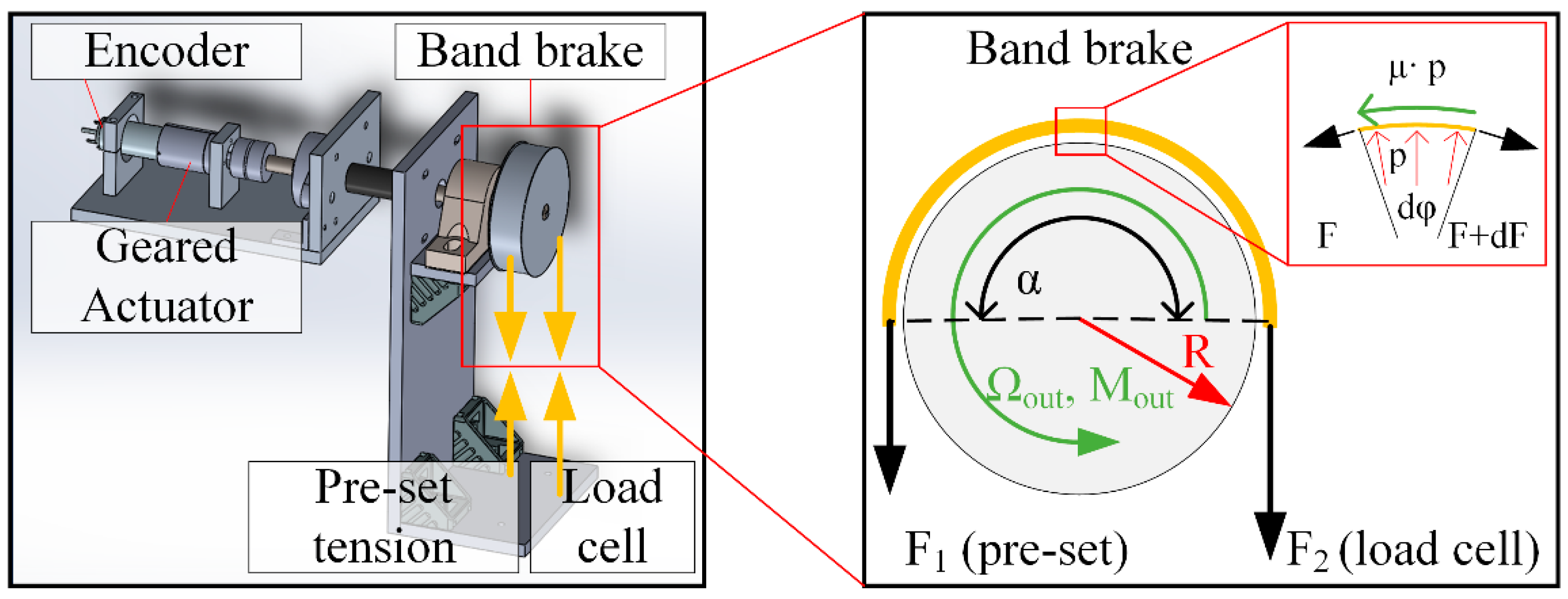
2.1.4. Dynamometer to Estimate Efficiency

The relative power efficiency, E r , of the gearbox can be estimated by comparing the power output registered at the dynamometer, P o u t , with the power input, P i n , to the gearbox that is supplied by the pinion attached to the DC-motor axle, as shown in Equation (1).
E r = P o u t P i n
The mechanical power, P , produced by a rotary system is given by torque, T , times the rotational speed, ω . In the case of the gearbox power input, the rotational speed is registered directly by the motor encoder and can be readily retrieved. The torque produced by the DC-motor depends on the supplied current, I i n , and a motor-specific torque constant, k , and the input power can thus be expressed as in Equation (2).
P i n = ω i n · k · I i n
In order to retrieve the mechanical power output, P o u t , we need to determine the output speed, ω o u t , and torque, M o u t . The speed is readily retrieved by the Hall-effect sensors mounted at the output or by simply reading the encoder speed after compensating for the gear reduction ratio. The output torque is given by the difference in forces acting on the disk radius of the band brake, and the output power is thus given by Equation (3). The brake radius is denoted R , while F denotes the forces acting on the band, with F 2 being the force registered by the load cell, as shown in Figure 4. Although F 1 is preset by the applied tension, it varies during operation, depending on the friction force acting on the band and must be estimated in order to retrieve the power output.
P o u t = ω o u t · R · ( F 2 F 1 )
The Euler–Eytelwein equation describes the dependency on friction of the band forces. The friction coefficient between band and brake drum is denoted μ , and the contact angle between band and brake drum is denoted by α . The force acting on the load cell, F 2 , is known, and the remaining force F 1 is given by Equation (4):
F 1 = F 2 · e μ α
Inserting Equation (4) into Equation (3) provides the output torque. Assuming constant friction coefficient, the expression can be simplified, and the torque can be retrieved from the force measured by the load cell multiplied with the speed and a gain factor, G, that incorporates all constants, as shown in Equations (5)–(7).
P o u t = ω o u t · R · F 2 ( 1 e μ α )
G = R · ( 1 e μ α )
P o u t = ω o u t · F 2 · G
The friction coefficient, µ, was determined to 0.5 by calibrating the dynamometer with a torque sensor.

2.2. Methodology for Tribology Analysis

2.2.1. Analysis of Worn Surfaces by Complementary Technique

The complementary technique for surface analysis described in this section is based on combining data from digital light optical microscopy (LOM), 3D-profilometry (3DP), and scanning electron microscopy (SEM), including energy dispersive X-ray spectroscopy (EDS). The purpose was to employ a set of techniques that complement each other and is necessary for this type of tribological research, since neither technique on its own can resolve the details that are important. The light optical microscope (LOM) provides a visual overview of the surface, including the general surface morphology. The visual information from the LOM can provide an initial indication of the damage phenomena and is also likely to provide a rough visualization of a chemically altered surface. Effects, such as corrosion or tribofilm formation, tend to alter the optical properties of the surface and can, therefore, be indicated by LOM. The light optical microscope, however, cannot accurately quantify the amount of wear or quantify the surface topography. For this purpose, the 3D-profilometer (3DP) provides surface topography with nm height resolution and can quantify wear accurately by comparing topography before and after the test. The surface topography information is also very important to indicate the type of lubrication regime that the contact is operating within, as the topography affects the propensity of the surface to generate hydrodynamic lubrication. The downside of 3DP is that it does not provide any cues about the presence of tribofilms, which is necessary to explain lubrication performance in boundary (including starved) lubrication conditions. Chemical elements that exist on rubbed surfaces can be detected by SEM–EDS. If the tribofilms are thin (less than 10 nanometers), the analytical depth of the SEM–EDS technique may be too deep, rendering the tribofilms invisible, and other methods, such as X-ray photoelectron spectroscopy (XPS), may be required. Assuming that the tribofilms are within the information depth obtained by EDS, the technique will provide the elemental contents in the film, which, again, provide important evidence of boundary lubrication. An example of this complementary technique can be found in our previous work, and further information can be found in references [21,35]. This type of analysis is nondestructive and well-suited to flat or convex surfaces that are easily accessible, such as the planet gear teeth, separator discs, or planet carrier shafts. Concave surfaces, such as the sleeve surface or the ring gear, require destructive analysis to gain access to the surface.

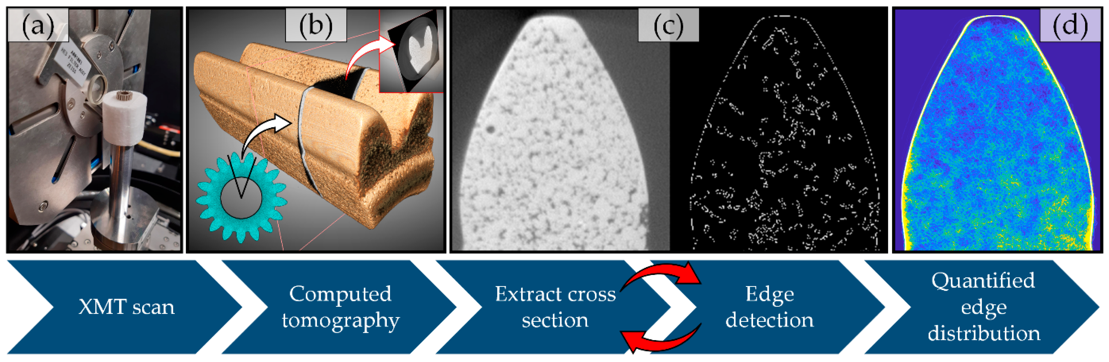
2.2.2. Subsurface Analysis by X-ray Microtomography

X-ray microtomography (XMT), also known as computed tomography in the microscale (µCT), is a three-dimensional sectional imaging technique for nondestructive material microstructure characterization [36]. The technique has gained increasing popularity over the last decade for characterization of dense engineering materials [37]. In XMT analysis, an X-ray beam is passed through a sample that is mounted on a rotary stage, while the attenuated X-ray signal is projected onto a detector placed opposite to the beam source. Digital image recognition techniques are employed to compute the sample tomography from the different projections, and a three-dimensional model of the scanned sample’s interior structure is obtained.
Based on XMT, we devised a methodology suitable for localizing and quantifying subsurface damages in small scale sintered metal gears, as illustrated Figure 5. We hypothesized that the alternating stress cycle combined with high friction during lubricant-starved conditions could make the planet gears susceptible to interior damages, such as subsurface or internal fatigue cracks, and that such cracks could be detectable by XMT. Furthermore, we expect lubricants that reduce friction under boundary lubrication conditions to also reduce the propensity of such crack formations, due to a reduction in near surface shear stress.
The employed XMT system—the ZEISS Xradia 510 Versa (Carl Zeiss X-ray Microscopy, Pleasanton, CA, USA)—is also referred to as a 3D X-ray microscope (XRM), as it has multiple detector objectives that enable sample imaging at a number of resolutions and field of view combinations, in a manner analogous to a light microscope. Samples were scanned at an X-ray tube voltage of 140 kV, a tube power of 10 W, using a 4x objective with 4 mm field of view for a good balance of resolution and field of view. Optionally, a submicron resolution could be achieved by use of the 20x objective, at the expense of a smaller field of view.
The gear samples were scanned either as complete gears, as shown Figure 5a, or as a pair of gear teeth that were cut out by electric discharge machining (to enable surface analysis by 3DP and SEM–EDS), as was the case in Figure 5b–d. A minimum voxel (volume pixel) resolution of 2 µm was achieved over the entire volume of the gear teeth for the samples that were cut, which resulted in a 90 GB data set describing the interior structure of the two gear teeth. The computed tomography data was handled using the software Dragonfly Pro (Object Research Systems, QC, Canada), and cross-sectional images at every resolved voxel layer was exported to produce a sequence of images (tiff-stack), as indicated in Figure 5b. The stacking direction was chosen along the axial coordinate (along gear flanks) for optimum visibility of cracks that were expected to form in the direction roughly perpendicular to the flank surface. In total, 3525 cross-sectional images were exported, corresponding to 1 image at every 2 µm of the 6 mm wide gear. Each image provided 1963 × 2021 pixels at 16-bit resolution, for a total of 30 GB.
An algorithm was designed using Matlab R2020a (The MathWorks Inc., Natick, MA, USA) to enable evaluation of extracted cross-sectional images in the search for interior features, such as subsurface cracks. The algorithm can be described in five steps. In the first step, cross-sectional images are sequentially retrieved and preprocessed by rotating and cropping each image to a predefined area of interest. Usually, the area of interest would be the cross-section of a complete gear tooth, but other areas, such as nonworn reference areas, can be defined in this step. Secondly, we employ the Canny edge detection method [38] to the processed image to obtain a two-dimensional binary array (602 × 542) that describes the edge distribution over the cross-section of the gear. The detection thresholds in the Canny filter were set to 0.05 and 0.50, which was sufficient to provide a robust detection of the exterior edge, while also capturing the interior features of the gear, as shown in Figure 5c. In the third step, horizontal and vertical reference lines are defined in the binary array by the intersection of the reference lines with the exterior edge of the gear. In the fourth step, circular shifting in the x and y direction is employed to the array, in order to align with neighboring arrays in the image sequence. Finally, the binary 2D-arrays, representing the cross-sections along the gear tooth, are summed to obtain the total distribution of edges, as shown in Figure 5d. The processing time of the algorithm was a matter of minutes when executed at the highest resolution. The algorithm is intended to provide a simple method for processing the 30 GB dataset obtained by XMT, in order to retrieve the key interior microstructure information relevant to gear tribology.

2.3. Verification and Validation—Space-Grade Oils under Starved Conditions

A case study was conducted to demonstrate the utility of the geared actuator test rig (GATR) for evaluating and analyzing the lubrication performances. The test geared actuators (RE30, 24 V 60 W, GP32A 51:1) were obtained from maxon (maxon motor ag, Sachseln, Switzerland). Six (6) actuator units were evaluated by accelerated testing under oil-starved conditions. The received actuators were disassembled and subjected to a meticulous cleaning process, in order to remove the standard grease. The gears were rinsed in heptane followed by sequential ultrasonic cleaning in heptane and ethanol. The cleaning process was repeated several times, and the gearboxes were carefully inspected to ensure a clean interior. Finally, the gearboxes were dried for 1 h at 80 °C, in order to evaporate ethanol absorbed into the porous gears, before supplying the test lubricants.
Apart from verification and validation, the objective of the study was to investigate planetary gears subjected to oil-starved conditions. It was not immediately obvious to focus the study on the gears, as they are not considered to be the element most likely to fail catastrophically in actuator gearboxes. Sleeve or rolling element bearings are both sensitive to effects of oil starvation and are at risk of catastrophic failure if operated at very low temperatures, such as those encountered in robotic space missions [27,31]. The issue with sleeve tribology has recently been addressed when employing commercially off-the-shelf (COTS) actuators in space, and it is possible to design actuator gearboxes with needle bearings instead of sleeves so that the issue is circumvented [30]; therefore, this study did not consider sleeve damages. Regarding rolling element bearings, one of the main factors of reduced lifetime is particulate contaminants in the oil, since a hard contaminant particle can damage bearing raceways if it is over-rolled. If the dimensions of the particle are larger than the bearing oil film thickness that separates the rolling element from the raceway, the particle will cause an indent into the bearing raceway that can initiate the chain of events leading to bearing seizure [39]. Under oil-starved conditions, particulate contaminants in the oil are even more problematic, as the oil film thickness is reduced by the restricted oil supply. In starved conditions, it, therefore, makes sense to investigate the source of wear particles, especially in a small-scale actuator gearbox, where it is not feasible to circulate and filter the oil from wear particles, as could be done in larger industrial gearboxes. In contrast to bearings, gears are usually subjected to a gradual wear process that inevitably produces wear particles. Consequentially, even though this methodology mainly addresses gear tribology, the implications should be valuable to the overall life of geared actuators as improved gear tribology improves the overall condition of the lubricant in the gearbox.
In order to investigate gear tribology under oil-starved conditions in these actuators, the applied volume of oil should be reduced to a minimum. In order to find the lower limit and to clarify the failure mode under dry conditions, one actuator unit was tested without lubricant. As could be expected from the discussion above, this unlubricated unit failed by seizure in the planet gear sleeve interface at gear stage 3 within one minute of operation under otherwise nominal conditions. Clearly, the applied oil needs to be sufficient to prevent immediate seizure in the stage 3 planet gear sleeves, while limiting the oil supply to the gear mesh.
According to conventional elasto-hydrodynamic lubrication theory, effective full film lubrication requires the formation of an oil film having a thickness, h , that is at least three times larger than the composite surface roughness, S q , or else the lubrication mode transitions toward the boundary regime where the surfaces are at risk of direct contact [40]. In oil-starved conditions, the restricted oil supply hinders the buildup of the oil film thickness, which increases the risk of operation in boundary conditions. The film parameter, Λ , shown in Equation (8) is commonly applied as an indicator of the mode of lubrication. If Λ < 3 , it indicates an insufficiently lubricated contact, such as the starved contact we are striving for in this experiment.
Λ = h S q
Based on this conventional film parameter, we can set a simple criterion that allows us to make a reasonable estimate of the amount of oil to apply in order to test the gears under starved conditions, while simultaneously providing the maximum oil supply to the sleeve bearings. The applied oil should provide an oil film having a thickness, h a p p l i e d , that is below the criteria for full film lubrication, as expressed in Equation (9).
h a p p l i e d < 3 S q
Assuming that the applied oil volume, V applied , spreads evenly over the total surface area to be lubricated, A tot , it will form an oil film of constant film thickness, determined simply by Equation (10).
h a p p l i e d = V a p p l i e d A t o t
By inserting Equation (10) into Equation (9) and rearranging the terms, we find an expression that determines the optimum amount of oil to apply, V a p p l i e d , as a function of the total surface area, A t o t and the composite surface roughness, S q . The volume of oil that should be applied, V a p p l i e d , is thus described by Equation (11).
V a p p l i e d < 3 · S q · A T o t
Numerically, the pinion to planet gear mesh composite surface roughness, S q , was measured by 3D-profilometer to 2.5 µm (2.5 × 10⁻³ mm). The total surface area, A t o t , of the lubricated interfaces in gear stage 3—including separator disc, three planet gears, pinion gear, ring gear—was measured to approximately 2.5 ×103 mm2. Equation (4) thereby indicates that the applied oil volume should be below 19 mm3 for gear stage 3, in order to ensure starved conditions. Based on the above explanation, 5 mm3 oil was applied to each of the three planet gears, for a total of 15 mm3. The same amount was also applied to gear stages 1 and 2, as well as the output ball bearing assembly, for a total oil fill of 60 mm3, or ~50–110 mg ( ρ A = 0.841 ,   ρ P = 0.841 ,   ρ B = 1.85 g/cm3), as compared to the standard 1.6 grams of grease fill.
Three different oil samples were included in the study. The selection of oils was based on the suitability of the oils to validate the methodology of accelerated testing under oil-starved conditions. Two of the oils employed have significant space heritage and were included as references. These heritage lubricants have markedly different oil chemistry from each other—a multiply alkylated cyclopentane (MAC) and a perfluoroalkyl polyether (PFPE) oil—and can thus be expected to display different performance characteristics when evaluated in the geared actuator experiment. These heritage oils are referred to in this work as “Heritage Oil A” and “Heritage Oil B,” representing MAC and PFPE, respectively. The third oil sample was an experimental vacuum oil candidate that has been investigated in various model scale experiments [21,35,41] and also recently, by use of the methodology described herein [26]. This oil is referred to as “Prototype Oil,” and, importantly, it consists of the same base oil as “Heritage Oil A,” so that their rheological properties are effectively equivalent. The difference between these samples is the incorporation of a low concentration of ionic liquid (IL) [42] in the “Prototype Oil,” which is expected to significantly alter the performance under conditions of insufficient lubricant film thickness. The prepared actuator units were assigned unique unit identfiers, as listed in Table 2, and the test sequence of lubricants was chosen in order to assist in verifying the repeatability of the method.
The conditions of the geared actuator test rig (GATR) experiment are presented in Table 3. The experiments were conducted in sequence. Each gearbox was cleaned and prepared with the test lubricant as described previously in this section, and the gearbox was manually rotated to distribute the oil. Before the gearbox was connected to the motor, each motor was tested, and the current draw was measured to ensure the repeatability of the motors. The deviation in current supply was approximately ± 1 % between the individual motors, which was deemed negligible in this experiment. After assembling the gearbox to the motor, the actuator current draw was again measured. No difference could be detected between the units lubricated with Heritage Oil A and the Prototype Oil, which had equivalent viscosity, whereas Heritage Oil B displayed 8% higher current draw. The higher current draw under no load conditions was thus attributed to the higher viscosity of Heritage Oil B. After inspection, the test actuator was mounted in the GATR and left overnight for thermal stabilization in the refrigerated chamber. The test was manually initiated when the chamber temperature had reached below −17.5 °C and the oxygen concentration had dropped to below 1%. The tests were conducted for 60 min, divided into 12 cycles of 5 min (300 s) each. During the cycle, the motor was started from standstill and accelerated to 8050 rpm at a rate of 1000 rpm/s. After the maximum speed was reached, the speed was maintained at 8050 for the remainder of the cycle to provide unidirectional motion. A constant brake torque of 0.9 Nm was applied and maintained for the entire duration of the test, corresponding to a maximum gear contact stress of ~0.25 GPa [43]. The data acquisition system recorded motor input current, I in ; motor speed, ω in ; dynamometer force, F 2 ; chamber temperatures, T A ; and gearbox housing temperature, T Gearbox , at 10 Hz during the duration of the test.

3. Results and Discussion

3.1. Methodology for Tribology Analysis—Assembled GATR

The assembled geared actuator test rig is shown in Figure 6. The photos show the GATR in the idle position, with the interior refrigerated chamber open to the ambient atmosphere. When conducting experiments at low temperature, the atmospheric chamber was tilted to the vertical configuration, and the environmental chamber was placed into the interior refrigerated compartment.

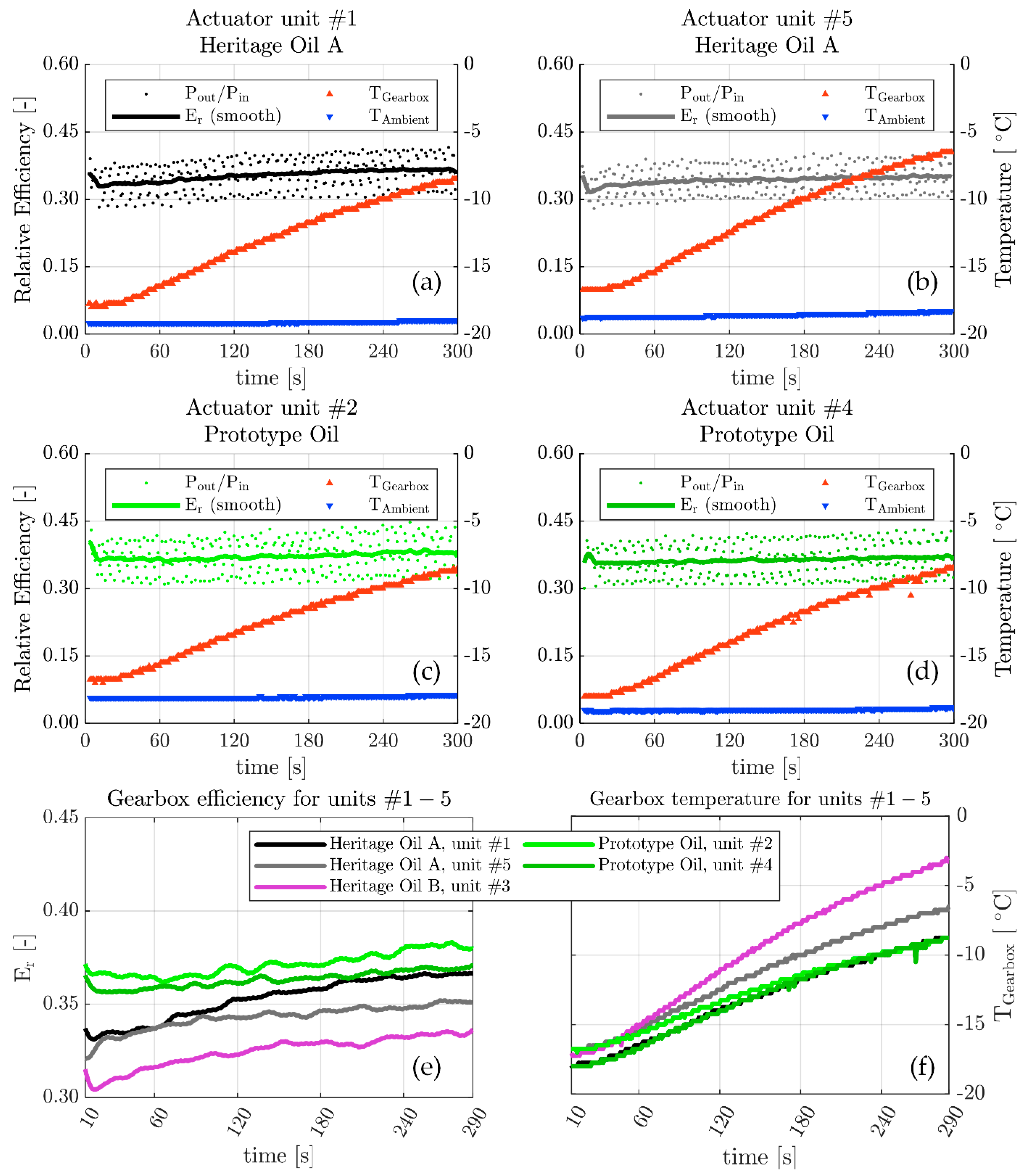
3.2. Verification and Validation of the GATR

Figure 7 displays results of the geared actuator test rig verification and validation experiments, conducted under dry nitrogen atmosphere at −20 °C nominal temperature. The actuators were started from the stationary position at time zero, and the speed was linearly ramped up to 8000 rpm during the initial 10 seconds. A preset load was applied to the dynamometer, corresponding to a nominal output torque of 0.8 Nm. The applied torque corresponds to ~20% of the maximum rated torque for these gearboxes.
In Figure 7a–d, the left vertical scale displays the relative efficiency of the gearbox of the corresponding actuator unit. The dotted markers display the momentaneous power output divided by the power input, P o u t / P i n , and the solid line display the efficiency, E r , as filtered by a 10-point Gaussian-weighted moving average filter. The right vertical scale displays the temperature as registered by the gearbox housing sensor, T G , and as registered in the ambient environment inside the atmospheric chamber, T A . The top two graphs (Figure 7a,b) correspond to two individual units (#1 and #5) that were both lubricated with the Heritage Oil A, while the graphs in middle row (Figure 7c,d) correspond to the two units (#2 and #4) that were both lubricated with the Prototype Oil. The details of the single actuator unit #3, lubricated with Heritage Oil B, is not shown. For all actuators units (#1–5), a clear rise in gear housing temperature was observed. This effect can be explained by the heat dissipation, due to friction power loss in the gearboxes. During the initial 5 min, the ambient temperature remained unaffected, despite this experiment being conducted without the use of dry ice; however, after an extended duration, the temperature rose significantly, indicating the importance of active cooling. Regarding the efficiency, as seen in Figure 7a–d the efficiency is highest during the initial 10-second period during startup, likely due to the DC-motor operating less efficiently at high speeds. The actuators units lubricated with the Prototype Oil, shown in Figure 7c,d, display a very steady efficiency, while the actuators lubricated with the heritage oils display an efficiency curve with a slightly increasing trend.
The repeatability of the experiment when exchanging the actuator unit can be assessed by Figure 7e–f. As can be seen in Figure 7e, the two actuator units lubricated with the Prototype Oil display the highest efficiency, followed by the two units lubricated with Heritage Oil A, and the single unit lubricated by Heritage Oil B displays the lowest efficiency. The efficiency ranking is thus: Prototype Oil > Heritage Oil A > Heritage Oil B, which corresponds very well to recent experiments conducted in model scale tribotests [21]. There is no obvious correlation between efficiency and unit number, with the efficiency ranking being #2 > #4 > #1 > #5 > #3. The unit number also corresponds to the test number, so that unit #1 was the first to be tested, and unit #5 was last. The fact that there was no qualitative difference on the measured efficiency when exchanging the actuator unit demonstrates that the process of exchanging the gearbox was repeatable. When studying the gearbox temperature evolution, as shown in Figure 7f, it is clear that the relation to efficiency is inverted. This inverted relation serves as a verification of the measured efficiency, as it can be expected that the gearbox frictional power loss is dissipated as heat. Regarding the absolute values of the relative efficiency, these values should be considered a conservative (low) estimate. The test rig bearing friction power loss was omitted from the calculation, as well as the influence of the inertial energy in the dynamometer during the initial acceleration.
The significant increase on gearbox temperature by frictional heating should be considered when studying the low temperature influence on oil starvation. In this type of accelerated test, the actuator was used at 95% duty cycle, whereas, in practical space robotic applications, the duty cycle would be significantly lower, and the gearbox would cool down between cycles. Accelerated life testing could possibly underestimate the risk of low temperature oil starvation effects, due to the frictional heating. If the nominal amount of oil is employed, forced cooling may be required, even at low ambient temperatures, if the purpose is to investigate effects of oil starvation at low temperature. The procedure of applying a reduced oil volume should limit the effect of temperature rise, so that starved conditions can be investigated, even at increased temperatures. Overall, the results in Figure 7 and the discussion above demonstrate that the method employed is valid for qualitatively studying lubrication effects on geared actuator performance.
After completing 60 min of testing in the GATR, the gearboxes were disassembled, and the complementary surface analysis techniques were employed, to investigate the gears for signs of surface damage attributable to oil starvation. Figure 8 displays a small subset of the surface analysis, composed of a 3DP topography map overlaid on a SEM image. For analysis of gear damages by complementary techniques, readers are referred to our recent work [26], whereas this analysis is limited to validating the methodology for provoking oil starvation effects. The analysis shown focuses on the gears lubricated by Heritage Oil A, in comparison to the gears lubricated by the Prototype Oil. The two lubricants display the same rheological properties and are only differentiated by the addition of a surface-active additive in the Prototype Oil. The heritage oil used does not contain additives, and, therefore, any difference in performance should be mainly attributed to the tribofilm formation. The surface lubricated by Heritage Oil A, shown in Figure 8a, displays clear signs of scuffing, with wear particles adhered onto the gear flank. There are also clear signs of oil decomposition, which is known to occur under boundary-lubricated conditions with the oil in question [44]. The observation of this type of damage indicates insufficient lubrication, which supports the validity of the oil starvation method employed. In contrast to the Heritage Oil A, the surface lubricated by the Prototype Oil, shown in Figure 8b, did not display excessive surface damage, and the original pores of the sintered steel surface remain visible after the test, as clearly seen by 3DP. The absence of damage was further explored in [26], and the result was attributed to the formation of an effective tribofilm, which also supports the validity of the oil starvation method employed, by indicating that the gear was operating under insufficiently lubricated conditions.

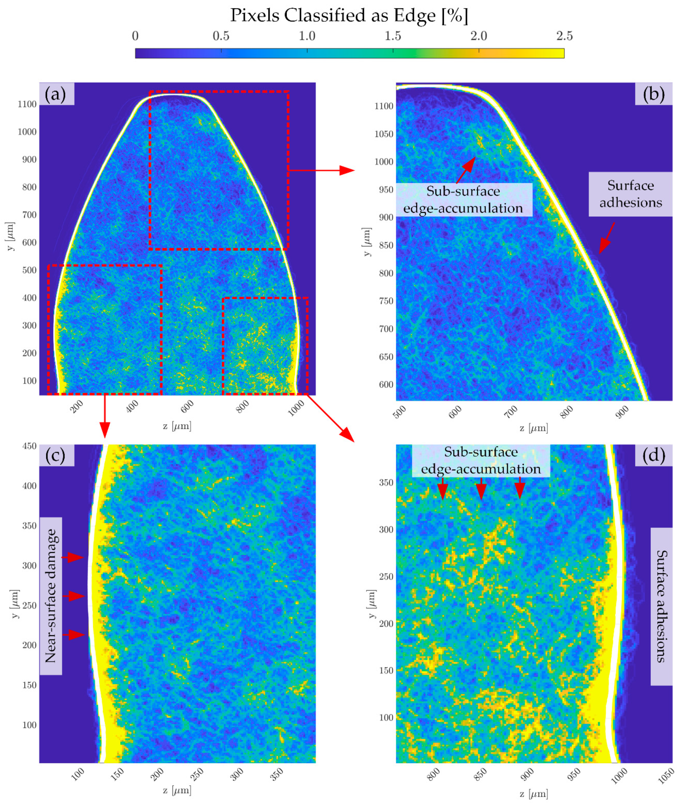
3.3. Validation of XMT-Methodology for Interior Analysis of Gear Tooth

Figure 9 displays results of the XMT analysis employed to a gear tooth lubricated by Heritage Oil B while subjected to testing in the GATR experiment. The analyzed gear tooth was part of a section physically separated from a stage 3 planet gear by means of electric discharge machining (EDM). Figure 9a presents the main output of the XMT algorithm devised in this work. The color scale in the image describes the intensity of detected edges per pixel of the gear cross-section. The colors are linearly scaled to the number of analyzed cross-sections, and the scale is capped at 2.5%. The detailed regions shown in Figure 9b–d correspond to Figure 9b, the driven flank addendum; Figure 9c, the driving side dedendum; and Figure 9d, the driven flank dedendum. As marked in the images, several features of interest were observed. Regions of subsurface edge accumulation—interpreted as an early sign of crack formation—was prevalent in the driven side dedendum. Due to the kinematics of the gear mesh, the driven side dedendum is subjected to a sliding motion that counteracts the rolling motion of the gear, with increased risk of oil film collapse. It is likely that the starved conditions amplified this effect to cause significant damage in the relatively short test duration. As seen in Figure 9d, surface adhesions could be resolved by the employed method, and this observation was confirmed by the complementary technique surface analysis (3DP, SEM, LOM). Extensive edge accumulations were observed underneath the surface adhesions, and the region of subsurface edge accumulations extended to a significant depth below the surface. The results clearly demonstrate that the XMT methodology enables observations that are highly useful to gear materials and lubricant design. Furthermore, the method may provide a means of early detection of interior damage. The duration of accelerated lifetime experiments could potentially be significantly reduced, while still retrieving information necessary to make lifetime predictions.

4. Conclusions

The following conclusions were inferred from this work:
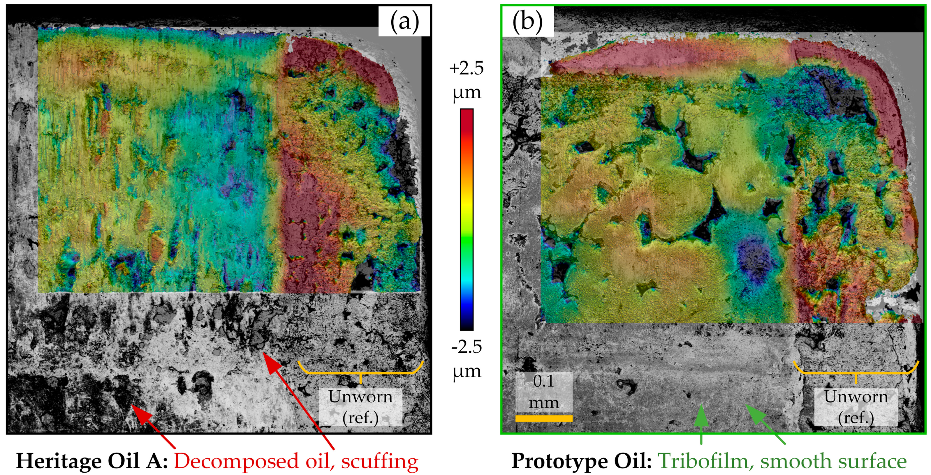
  • An experimental methodology—based on a laboratory test rig in combination with a specific analytical procedure—was developed for conducting tribological research using actual gearboxes for actuators in space applications.
  • A case study was conducted on space grade liquid lubricants under simulated space environment (−20 °C and nitrogen atmosphere) and oil-starved conditions to evaluate the lubrication performances of various lubricants. The Prototype Oil showed the ability to significantly improve performance in comparison to the references.
  • The observed results from the component scale case study correlate well with experiments at model scale. The results support the feasibility using the methodology for lab-to-field upscaling.
  • The methodology is applicable for evaluation and analysis of liquid lubricants and materials including functional coatings for use in space robotic actuators.
  • The developed protocol is also beneficial to study failure mechanisms on the component level, in order to better design model scale experiments. In addition, it can also utilize upscaling from the results in model scale studies. The XMT information is well-suited for correlations with numerical models, which can further assist upscaling.
  • Early diagnosis (detection) of subsurface damage (micropitting, cyclic fatigue) in gear teeth was possible with this test rig in combination with the devised XMT-methodology.
The designed test rig provides options for upgraded instrumentation and additional sensors as required. Improved capabilities in terms of vacuum chamber, forced cooling, high precision dynamometer, and increased motor controller current capacity are installable for task specific purposes.

Author Contributions

E.N. Design of Experiments (DoE) and analysis of GATR, 3DP, SEM, and XMT, mechanical engineering, electrical engineering, prototyping, software and algorithms, writing. D.L.iC. Prototyping, mechanical engineering, computer aided engineering. I.M. Project supervision, work guidance, results and manuscript revision. All authors have read and agreed to the published version of the manuscript.

Funding

This work was partially funded by the Taiho Kogyo Research Foundation (TTRF), through the 2019 First Research Grant provided, and partially funded by the Austrian COMET-Program InTribology1 (FFG-No. 872176) and was partially carried out at the “Excellence Centre of Tribology” (AC2T research GmbH).

Institutional Review Board Statement

Not applicable.

Informed Consent Statement

Not applicable.

Data Availability Statement

Data is contained within the article.

Acknowledgments

The authors are grateful for contributions from the following people at Luleå University of Technology: F. Nilsson and M. Lund—EDM and engineering discussions; K. Berglund, P. Gren, A. Kumar Baskar, A. Lindwall, and E. Rundgren–assistance in dry ice experiments within the course Experimental Methods (F0033T); H. Lycksam and F. Forsberg–XMT scans with helpful discussions; M. Söderfjäll–GATR engineering discussions; J. Hansen–surface analysis and general discussions; Group of Atmospheric Science–assistance during rapid prototyping; i-TRIBOMAT consortium–upscaling concept.

Conflicts of Interest

The authors declare no conflict of interest.

Nomenclature

µCTComputed tomography in the microscale
3DP3D-profilometer (scanning white light interferometry)
ADCAnalog-to-digital converter
COTSCommercially off-the-shelf
E r Relative efficiency (P_out/P_in)
EDMElectric discharge machining
EDSEnergy dispersive X-ray spectroscopy
ESCONServo controller (maxon)
GTorque gain factor (-)
GATR Geared actuator test rig
GPaGigaPascal
I/O Input/output
ILIonic liquid
LOMDigital light optical microscope
MACMultiply alkylated cyclopentane
ω i n Motor speed (rad/s)
ω o u t Dynamometer speed ( ω i n × 51.2 1 )
PFPEPerfluoroalkyl polyether
PIDProportional–integral–derivative
P i n Power input
P o u t Power output
PSUPower supply unit
PWMPulse width modulation
SEMScanning electron microscope
T A m b i e n t Temperature in atmospheric chamber
T G e a r b o x Temperature on gearbox housing
TRL Technology readiness level
XMTX-ray microtomography
XPSX-ray photoelectron spectroscopy
ρ A Density of “Heritage Oil A” (MAC): 0.841 g/mL
ρ B Density of “Heritage Oil B” (PFPE): 1.85 g/mL
ρ P Density of “Prototype Oil” (MAC + IL): 0.841 g/mL

References

  1. Sanguino, T.d.J.M. 50 years of rovers for planetary exploration: A retrospective review for future directions. Robot. Auton. Syst. 2017, 94, 172–185. [Google Scholar] [CrossRef]
  2. Wedler, A.; Schuster, M.J.; Müller, G.; Vodermayer, B.; Meyer, L.; Giubilato, R.; Vayugundla, M.; Smisek, M.; Dömel, A.; Steidle, F.; et al. German Aerospace Center’s advanced robotic technology for future lunar scientific missions. Philos. Trans. R. Soc. A Math. Phys. Eng. Sci. 2021, 379. [Google Scholar]
  3. International Space Exploration Coordination Group. The Global Exploration Roadmap; European Space Agency, Directorate of Human and Robotic Exploration: Noordwijk, The Netherlands, 2018. [Google Scholar]
  4. International Space Exploration Coordination Group. Global Exploration Roadmap Supplement August 2020; European Space Agency, Directorate of Human and Robotic Exploration: Noordwijk, The Netherlands, 2020; pp. 1–19. [Google Scholar]
  5. Edelson, K.; Benjamin, B.; Dominguez, L.; Fuller, D.; Kennett, A. System-level actuator testing for mars rover application. In Proceedings of the 2018 IEEE Aerospace Conference, Big Sky, MT, USA, 3–10 March 2018; pp. 1–8. [Google Scholar] [CrossRef]
  6. Grandy, D.; Panek, N.; Routhier, G.; Ridolfi, P. Development And Qualification Of The Exomars Bogie Electro-Mechanical Assembly (Bema) Rotary Actuators. In Proceedings of the ESMATS–18th European Space Mechanisms and Tribology Symposium, Munich, Germany, 18–20 September 2019. [Google Scholar]
  7. Fleischner, R. Insight instrument deployment arm. In Proceedings of the ESMATS–15th European Space Mechanisms and Tribology Symposium, Noordwijk, The Netherlands, 25–27 September 2013. [Google Scholar]
  8. Roberts, E.W. Space tribology: Its role in spacecraft mechanisms. J. Phys. D. Appl. Phys. 2012, 45, 503001. [Google Scholar] [CrossRef]
  9. Jones, W.R.; Jansen, M.J. Tribology for space applications. Proc. Inst. Mech. Eng. Part J J. Eng. Tribol. 2008, 222, 997–1004. [Google Scholar] [CrossRef]
  10. The Boeing Company. Lunar Roving Vehicle Operations Handbook; The Boeing Company: Huntsville, AL, USA, 1971. [Google Scholar]
  11. Lee, G.Y.; Donaldson, J.A. Dreaming on Mars: How Curiosity performs actuator warm-up while sleeping. In Proceedings of the 2013 8th International Conference on System of Systems Engineering, Maui, HI, USA, 2–6 June 2013. [Google Scholar] [CrossRef]
  12. Lince, J. Effective Application of Solid Lubricants in Spacecraft Mechanisms. Lubricants 2020, 8, 74. [Google Scholar] [CrossRef]
  13. National Aeronautics and Space Administration (NASA). 2020 NASA Technology Taxonomy; NASA Office of the Chief Technologist: Washington, DC, USA, 2020. [Google Scholar]
  14. National Aeronautics and Space Administration (NASA). NASA Strategic Technology Investment Plan 2017; NASA Office of the Chief Technologist: Washington, DC, USA, 2017. [Google Scholar]
  15. Carré, D.J.; Kalogeras, C.; Didziulis, S.; Fleischauer, P.; Bauer, R. Recent experience with synthetic hydrocarbon lubricants for spacecraft applications. In Proceedings of the ESMATS–6th European Space Mechanisms and Tribology Symposium, Zurich, Switzerland, 4–6 October 1995. [Google Scholar] [CrossRef]
  16. Masuko, M.; Iijima, S.; Terawaki, T.; Suzuki, A.; Aoki, S.; Nogi, T.; Obara, S. Effect of surface oxide layer of steel on the tribological characteristics of load-bearing additives for multiply-alkylated cyclopentane oil under high vacuum. Tribol. Lett. 2013, 51, 115–125. [Google Scholar] [CrossRef]
  17. Peterangelo, S.C.; Gschwender, L.J.; Snyder, C.E., Jr.; Jones, W.R., Jr.; Nguyen, Q.N.; Jansen, M.J. Improved additives for multiply alkylated cyclopentane-based lubricants. J. Synth. Lubr. 2008, 25, 31–41. [Google Scholar] [CrossRef]
  18. Fan, X.; Wang, L.; Li, W.; Wan, S. Improving Tribological Properties of Multialkylated Cyclopentanes under Simulated Space Environment: Two Feasible Approaches. ACS Appl. Mater. Interfaces 2015, 7, 14359–14368. [Google Scholar] [CrossRef]
  19. Song, Z.; Liang, Y.; Fan, M.; Zhou, F.; Liu, W. Lithium-based ionic liquids as novel lubricant additives for multiply alkylated cyclopentanes (MACs). Friction 2013, 1, 222–231. [Google Scholar] [CrossRef] [Green Version]
  20. Zhang, S.; Hu, L.; Qiao, D.; Feng, D.; Wang, H. Vacuum tribological performance of phosphonium-based ionic liquids as lubricants and lubricant additives of multialkylated cyclopentanes. Tribol. Int. 2013, 66, 289–295. [Google Scholar] [CrossRef]
  21. Nyberg, E.; Schneidhofer, C.; Pisarova, L.; Dörr, N.; Minami, I. Ionic Liquids as Performance Ingredients in Space Lubricants. Molecules 2021, 26, 1013. [Google Scholar] [CrossRef]
  22. Hofmann, D.C.; Polit-Casillas, R.; Roberts, S.N.; Borgonia, J.-P.; Dillon, R.P.; Hilgemann, E.; Kolodziejska, J.; Montemayor, L.; Suh, J.; Hoff, A.; et al. Castable Bulk Metallic Glass Strain Wave Gears: Towards Decreasing the Cost of High-Performance Robotics. Sci. Rep. 2016, 6, 37773. [Google Scholar] [CrossRef] [Green Version]
  23. Hofmann, D.C. Bulk Metallic Glasses and Their Composites: A Brief History of Diverging Fields. J. Mater. 2013, 2013, e517904. [Google Scholar] [CrossRef]
  24. Dube, M.J.; Fisher, J.; Loewenthal, S.; Ward, P. Recovery and Operational Best Practices for Reaction Wheel Bearings. In Proceedings of the 45th Aerospace Mechanisms Symposium, Houston, TX, USA, 13–15 May 2020; pp. 277–286. [Google Scholar]
  25. Vellore, A.; Romero Garcia, S.; Johnson, D.; Martini, A. Ambient and Nitrogen Environment Friction Data for Various Materials & Surface Treatments for Space Applications. Tribol. Lett. 2021, 1–5. [Google Scholar] [CrossRef]
  26. Nyberg, E.; Hansen, J.; Minami, I. Lubrication concept evaluated for geared actuators under starved conditions. In Proceedings of the 45th Aerospace Mechanisms Symposium, Houston, TX, USA, 13–15 May 2020; pp. 255–260. [Google Scholar]
  27. Suffern, D.; Parker, J. Developmental Bearing and Bushing Testing for Mars Gearboxes. In Proceedings of the 44th Aerospace Mechanisms Symposium, Cleveland, OH, USA, 16–18 May 2018; pp. 529–541. [Google Scholar]
  28. Pirker, F.; Tóth, I.; Cihak-bayr, U.; Grundtner, R.; Vernes, A.; Benedicto, J.; Spaltmann, D.; Gradt, T.; Alberdi, A.; Alonso, I.; et al. Tribological Characterisation Services for Materials – i-TRIBOMAT. Tribol. und Schmierungstechnik 2020, 67, 33–48. [Google Scholar]
  29. Niebuhr, D. Friction and wear behavior of engineering materials in a simulated Martian (CO2) environment, a preliminary study. Wear 2007, 263, 88–92. [Google Scholar] [CrossRef]
  30. Loschiavo, M.; Phillips, R.; Mikhaylov, R.; Braunschweig, L. Mars 2020 maxon Commercial Motor Development from Commercial-Off-the-Shelf to Flight-Qualified Motors, Gearboxes, and Detent Brakes: Overcoming Issues and Lessons Learned. Aerosp. Mech. Symp. NASA JSC 2020, 45, 411–424. [Google Scholar]
  31. Suffern, D.; Mobley, J.; Smith, S. Mars 2020 Motor Bearing Failure, Investigation and Response. Aerosp. Mech. Symp. NASA JSC 2020, 45, 397–410. [Google Scholar]
  32. Li, X.; Olofsson, U. A study on friction and wear reduction due to porosity in powder metallurgic gear materials. Tribol. Int. 2017, 110, 86–95. [Google Scholar] [CrossRef]
  33. Flodin, A. Powder metal gear technology: A review of the state of the art. Power Transm. Eng. 2016, 67–77. [Google Scholar]
  34. Boidi, G.; Tertuliano, I.S.; Cano, M.F.; Machado, G.A.A.; Souza, R.M.; Machado, I.F. Tribological Evaluation of Sintered and Conventional Gear Materials. In Proceedings of the 26th SAE BRASIL International Congress and Display, São Paulo, Brazil, 7–9 November 2017. [Google Scholar]
  35. Nyberg, E.; Mouzon, J.; Grahn, M.; Minami, I. Formation of Boundary Film from Ionic Liquids Enhanced by Additives. Appl. Sci. 2017, 7, 433. [Google Scholar] [CrossRef] [Green Version]
  36. Landis, E.N.; Keane, D.T. X-ray microtomography. Mater. Charact. 2010, 61, 1305–1316. [Google Scholar] [CrossRef]
  37. Monteiro, S.N.; Paciornik, S. From Historical Backgrounds to Recent Advances in 3D Characterization of Materials: An Overview. Jom 2017, 69, 84–92. [Google Scholar] [CrossRef]
  38. Canny, J. A Computational Approach to Edge Detection. IEEE Trans. Pattern Anal. Mach. Intell. 1986, PAMI-8, 679–698. [Google Scholar] [CrossRef]
  39. Harris, T.A.; Kotzalas, M.N. Rolling Bearing Analysis: Essential Concepts of Bearing Technology, 5th ed.; CRC/Taylor {&} Francis: Boca Raton, FL, USA, 2007; ISBN 9780849371837. (inb.). [Google Scholar]
  40. Hamrock, B.J.; Schmid, S.R.; Jacobson, B. Fundamentals of Fluid Film Lubrication; McGraw-Hill series in mechanical engineering, 99-0109193-4 169; Marcel Dekker: New York, NY, USA, 2004; ISBN 0-8247-5371-2. [Google Scholar]
  41. Hansen, J.; Björling, M.; Minami, I.; Larsson, R. Performance and mechanisms of silicate tribofilm in heavily loaded rolling/sliding non-conformal contacts. Tribol. Int. 2018, 123, 130–141. [Google Scholar] [CrossRef]
  42. Nyberg, E.; Respatiningsih, C.Y.; Minami, I. Molecular design of advanced lubricant base fluids: Hydrocarbon-mimicking ionic liquids. RSC Adv. 2017, 7, 6364–6373. [Google Scholar] [CrossRef] [Green Version]
  43. American Gear Manufacturers Association (AGMA). Effect of Lubrication on Gear Surface Distress: AGMA 925-A03. AGMA Tech. Publ. 2003. [Google Scholar]
  44. Lu, R.; Minami, I.; Nanao, H.; Mori, S. Investigation of decomposition of hydrocarbon oil on the nascent surface of steel. Tribol. Lett. 2007, 27, 25–30. [Google Scholar] [CrossRef]
Figure 1. Schematic displaying general outline and salient sub systems of the geared actuator test rig (GATR).
Aerospace 08 00075 g001
Figure 2. (a) Disassembled gearbox with numerous tribological interfaces. (b) Model of planet gear, indicating three different tribological interfaces.
Aerospace 08 00075 g002
Figure 3. Layout of electronic system.
Aerospace 08 00075 g003
Figure 4. Dynamometer based on Euler–Eytelwein theory for band brakes.
Aerospace 08 00075 g004
Figure 5. Method for subsurface analysis by X-ray microtomography (XMT). (a) Gear placed on rotary sample holder to be scanned by XMT. (b) 3D representation of gear section created by computed tomography. (c) Tomographic images perpendicular to axial dimension of gear extracted, and analyzed by edge detection algorithm. (d) Edge distribution quantified by summation of detected edges.
Aerospace 08 00075 g005
Figure 6. Assembled geared actuator test rig in open position. (a) Details of refrigerated interior side. (b) Side view.
Aerospace 08 00075 g006
Figure 7. Relative efficiency and temperature measurements to demonstrate the geared actuator test rig (GATR) functionality. (a,b) Two repeated experiments using actuator units #1 and #5, both lubricated with Heritage Oil A. (c,d). Two repeated experiments using actuator units #2 and #4, both lubricated with Prototype Oil. (e) Comparison of gearbox units #1–5 efficiency over test duration (filtered and edge effects omitted). (f) Comparison of gearbox temperature for units #1–5 over test duration (unfiltered).
Aerospace 08 00075 g007
Figure 8. Oil starvation is indicated by the boundary lubrication phenomena observed in surface analysis by 3D-profilometry (3DP) and scanning electron microscopy (SEM). (a) Scuffing and decomposition of oil observed when lubricated with Heritage Oil A. (b) Tribofilm formation and smooth surface observed when lubricated with Prototype Oil.
Aerospace 08 00075 g008
Figure 9. XMT analysis of a gear lubricated by Heritage Oil B. (a) Overview of the internal edge distribution as detected by the employed XMT algorithm. (b) Detailed view of the addendum part of the gear on the driven side, indicating slight accumulation of subsurface damage. (c) Detailed view of the dedendum part of the driving side, indicating near-surface damage. (d) Detailed view of the dedendum part of the driven side, indicating extensive subsurface edge accumulations, interpreted as early signs of crack formation.
Aerospace 08 00075 g009
Table 1. Items composing the electronic control system and instrumentation.
ReferenceItem (Supplier)Main FunctionsKey Specifications
ArduinoArduino Mega 2560, (Arduino LLC, Boston, MA, USA)Microcontroller for main data acquisition and control. Communicates with ESCON, ADCs, and SD Shield.Digital input/outputs: 54.
Clock speed 16 MHz.
Flash memory 128 kb.
SRAM 8 kb.
SD ShieldArduino Ethernet shield R3
(Arduino LLC, Boston, MA, USA)
Data storage by SD memory card, and network communication by Ethernet.Data storage at 10 Hz.
ESCONESCON 36/2,
(maxon motor ag, Sachseln, CH)
DC servo PWM controllerMotor control by closed loop PWM at 53.6 kHz.
Output current: 2/4 A (continuous/intermittent).
EncoderHEDL 5540 Encoder
(maxon motor ag, Sachseln, Switzerland)
Communicate motor speed, N in , and motor current, I in to ESCON.Resolution: 500 counts per turn
Frequency: 100 kHz
TCType-K TC with MAX 31,855 ADC
(Adafruit Industries, LLC, New York, NY, USA)
Thermocouple (TC) and analog–digital converter (ADC) for recording gearbox housing temperature, T Gearbox .Tmp. range and accuracy (°C):
(−200–+200), ± 2
Frequency: 10 Hz
TADHT22
(Adafruit Industries, LLC, New York, NY, USA)
Interior sensor for recording chamber ambient temperature (Tmp) and relative humidity (Hum), integrated ADC.Tmp. range, and accuracy:
(−40–+125), ± 0.2 °C
Hum. range, and accuracy:
range: (0–100), ± 2 (%RH)
Frequency: 0.5 (Hz)
Load cellLoad cell TAL220 and HX711 ADC
(SparkFun Electronics Inc., Boulded, CO, USA)
Load cell (Straight bar strain gauge) withFull scale load range (FS):
(0–98) (N)
Combined error: ± 0.05 (%FS) Creep: ± 0.05 (%FS/3 min)
Hall SensorSS441A (Honeywell International Inc., Charlotte, NC, USA)Communicate dynamometer speed, N out to ArduinoResolution: 2 counts per turn
Frequency: 10 Hz
(limited by control scheme)
O2 monitorAJX-N2,
(AS ONE Corp., Osaka, Japan)
Monitor oxygen levelO2 range: 0–30%
Accuracy: ± 0.5%
Table 2. Test samples and order of test sequence.
Test NumberActuator Unit IdentifierOil
1#1Heritage Oil A
2#2Prototype Oil
3#3Heritage Oil B
4#4Prototype Oil
5#5Heritage Oil A
Table 3. Test rig set points and outputs.
Set Points
O2
(%)
T ambient
(°C)
M out
(Nm)
ω in
(rpm)
Duration
(s)
< 1 20 ± 2.5 0.9 ± 0.1 8050 12 × 300
Outputs
P i n
(W)
P o u t
(W)
ω in
(s−1)
ω out
(s−1)
T Gearbox
(°C)
T Ambient
(°C)
Publisher’s Note: MDPI stays neutral with regard to jurisdictional claims in published maps and institutional affiliations.

