
Aerodynamic Performance of a Coaxial Hex-Rotor MAV in Hover


Abstract
:1. Introduction
2. Aerodynamic Analyses
- —air density at the height of rotor [Kg/m3].
- —rotor-tip speed [m/s].
- —average chord length of rotor [m].
- —dynamic viscosity of the air [Pa·s].
- P—power consumption of the rotor system [W].
- A—rotor disc area [m2].
- m, n—mth and nth rotor for the rotor system., —ideal induced velocity for the isolated mth and nth rotor [m/s].
- —correction for the additional induced loss of a real rotor.
- —interference factor.
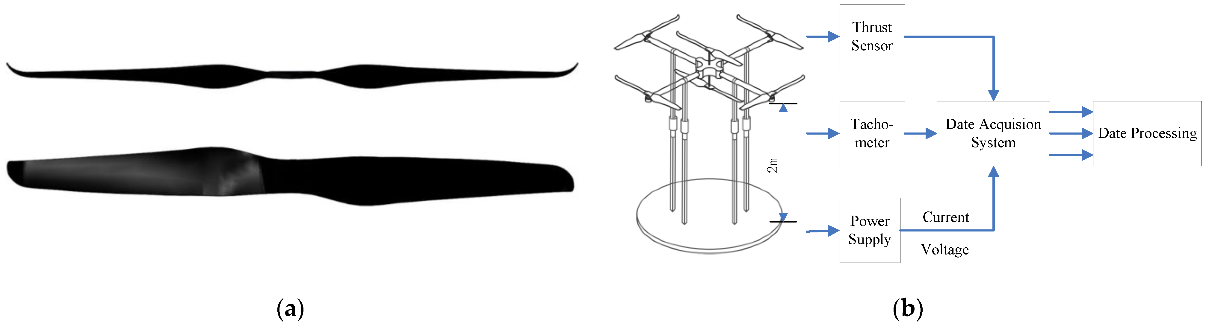
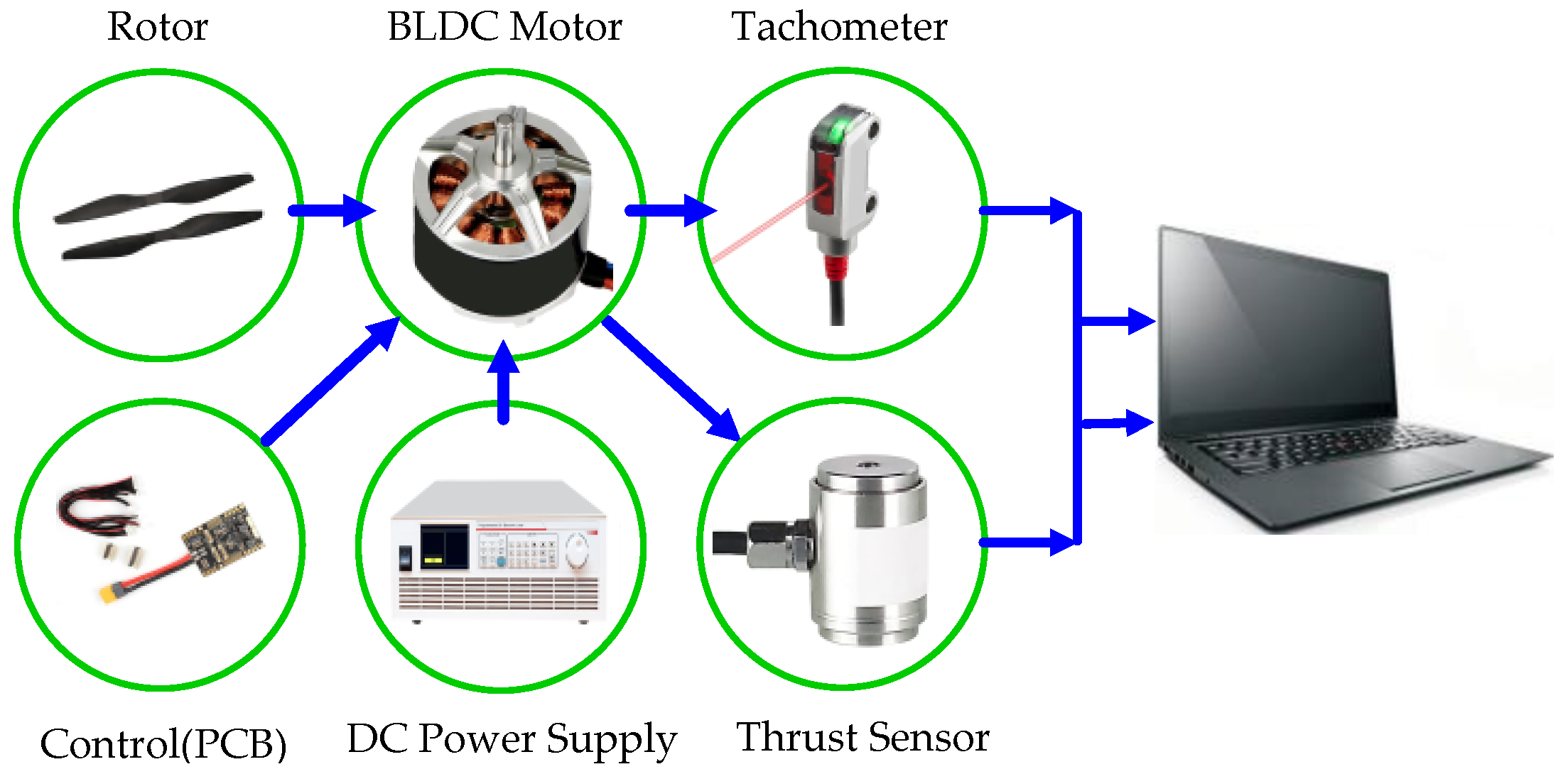
3. Experiments
3.1. Setup
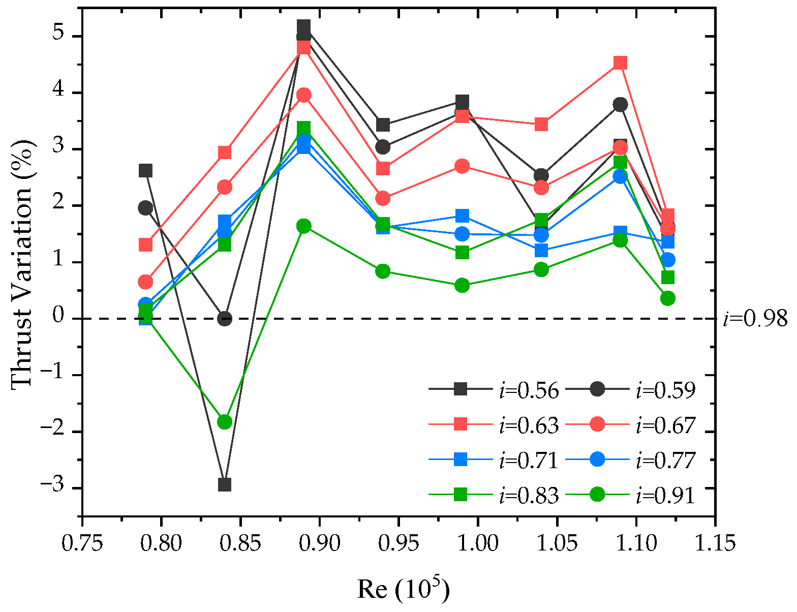
3.2. Results
4. Simulations
4.1. Setup
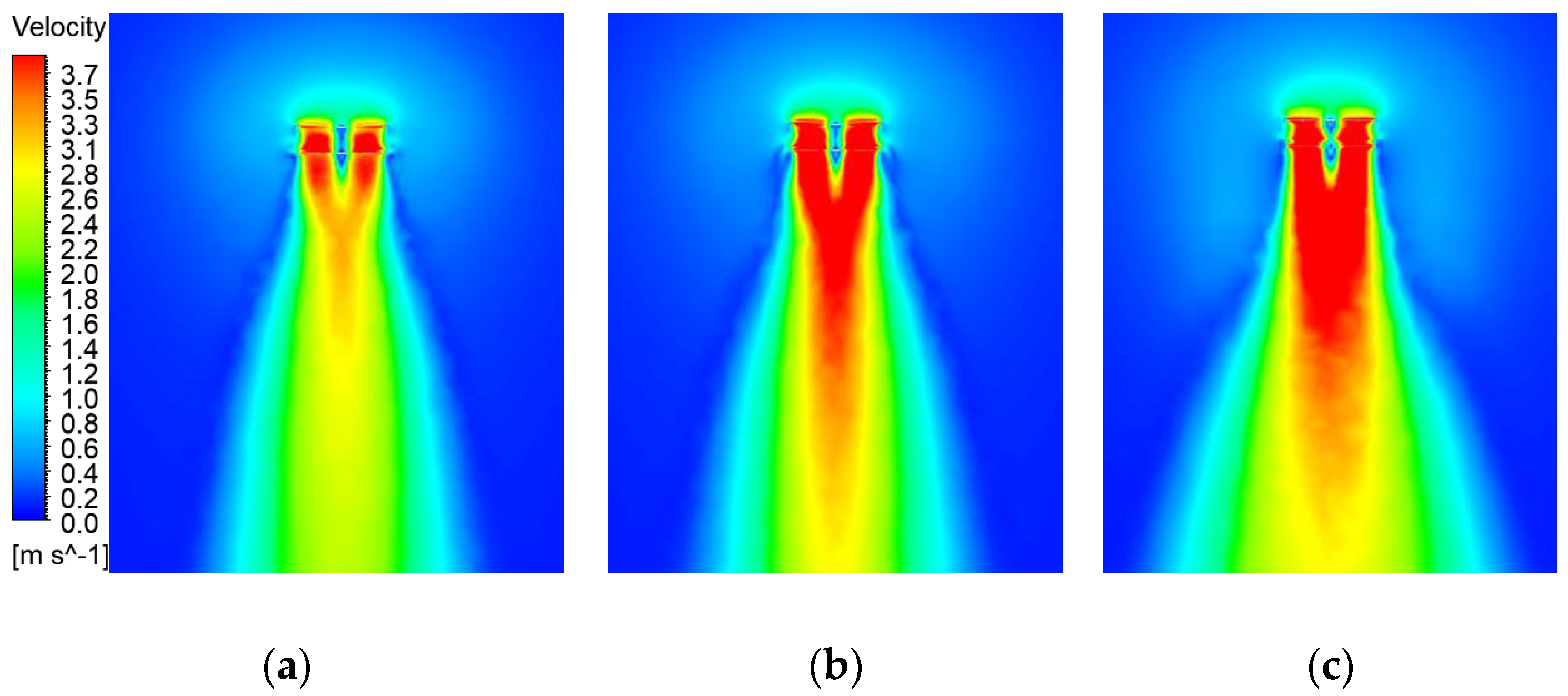
4.2. Results
5. Conclusions
- The experimental results showed that the aerodynamic characteristics and hover performance of MAVs can be improved notably by adjusting the horizontal distance between rotors.
- The data presented exhibited a weak tendency of inter-rotor interference with the decreased rotor spacing ratio. The multi-rotor system has the optimized thrust, power, and hover performance with rotor rotational speed ranging from 1600 RPM to 2300 RPM at i = 0.56.
- The numerical simulation showed that the presence of the strong inter-rotor vortices led to a significant degradation in aerodynamic performance at a small rotor spacing, resulting in unsteady wake behaviors.
- Inter-rotor vortices and turbulence flows in the horizontal direction were the major manifestations of the interference between adjacent single and coaxial rotors.
- As the rotor spacing ratio decreases, the pressure difference on the rotor surface enlarged, and the velocity of the downwash increased. The aerodynamic disturbance is expected to be the weakest at the spacing ratio i = 0.56.
- The novel multi-rotor layout provides larger thrusts compared to conventional MAVs of the same size while exacerbating inter-rotor aerodynamic interference. Although a slight reduction (2.03%) in overall thrust was measured compared to an isolated rotor system, the wind resistance is improved by the accelerated rotor-tip downwash.
Author Contributions
Funding
Institutional Review Board Statement
Informed Consent Statement
Data Availability Statement
Acknowledgments
Conflicts of Interest
References
- Hein, B.R.; Chopra, I. Hover Performance of a Micro Air Vehicle: Rotors at Low Reynolds Number. J. Am. Helicopter Soc. 2007, 52, 254–262. [Google Scholar] [CrossRef]
- Lakshminarayan, V.K.; Baeder, J.D. Computational Investigation of Microscale Coaxial-Rotor Aerodynamics in Hover. J. Aircr. 2010, 47, 940–955. [Google Scholar] [CrossRef] [Green Version]
- Hassanalian, M.; Rice, D.; Abdelkefi, A. Aerodynamic performance analysis of fixed wing space drones in different solar system bodies. Acta Astronautica 2018, 152, 27–48. [Google Scholar] [CrossRef]
- Herrero, A.D.E.; Percin, M.; Karasek, M.; Van Oudheusden, B. Flow Visualization around a Flapping-Wing Micro Air Vehicle in Free Flight Using Large-Scale PIV. Aerospace 2018, 5, 99. [Google Scholar] [CrossRef] [Green Version]
- Sibilski, K.; Nowakowski, M.; Rykaczewski, D.; Szczepaniak, P.; Żyluk, A.; Sibilska-Mroziewicz, A.; Garbowski, M.; Wróblewski, W. Identification of Fixed-Wing Micro Aerial Vehicle Aerodynamic Derivatives from Dynamic Water Tunnel Tests. Aerospace 2020, 7, 116. [Google Scholar] [CrossRef]
- Bohorquez, F.; Pines, D. Hover Performance of Rotor Blades at Low Reynolds Numbers for Rotary Wing Micro Air Vehicles. In Proceedings of the 2nd AIAA Unmanned Unlimited Conference and Workshop & Exhibit, Orlando, FL, USA, 23–26 June 2003. [Google Scholar]
- Piccinini, R.; Tugnoli, M.; Zanotti, A. Numerical Investigation of the Rotor-Rotor Aerodynamic Interaction for eVTOL Aircraft Configurations. Energies 2020, 13, 5995. [Google Scholar] [CrossRef]
- Hidemasa, Y.; Keiichi, K.; Yoshiaki, N. Numerical analysis of flow field and aerodynamic characteristics of a quadrotor. Trans. Jpn. Soc. Aeronaut. Space Sci. 2013, 11, 61–70. [Google Scholar]
- Tulwin, T. Low Reynolds Number Rotor Blade Aerodynamic Analysis. MATEC Web Conf. 2019, 252, 04006. [Google Scholar] [CrossRef]
- Sang, H.P.; Kwon, O.J. Numerical study about aerodynamic interaction for coaxial rotor blades. Int. J. Aeronaut. Space Sci. 2021, 22, 277–286. [Google Scholar]
- Lei, Y.; Ji, Y.; Wang, C. Numerical Simulation and Experimental Validation of Small-rotor Aerodynamic Characteristics. In Proceedings of the International Conference on Mechatronics Engineering & Information Technology, Xi’an China, 27–28 August 2016. [Google Scholar] [CrossRef] [Green Version]
- Johnson, W. Twin Rotor Interference in Forward Flight. In Helicopter Theory; Dover: New York, NY, USA, 1994; p. 142. [Google Scholar]
- Lei, Y.; Bai, Y.; Xu, Z.; Gao, Q.; Zhao, C. An experimental investigation on aerodynamic performance of a coaxial rotor system with different rotor spacing and wind speed. Exp. Therm. Fluid Sci. 2013, 44, 779–785. [Google Scholar] [CrossRef]
- Lee, H.; Lee, D.J. Rotor interactional effects on aerodynamic and noise characteristics of a small multirotor un-manned aerial vehicle. Phys. Fluids 2020, 32, 47107. [Google Scholar]
- Lee, S.; Chae, S.; Woo, S.Y.; Jang, J.; Kim, J. Effects of Rotor-Rotor Interaction on the Wake Structure and Thrust Generation of a Quadrotor Unmanned Aerial Vehicle. IEEE Access 2021, 9, 85995–86016. [Google Scholar] [CrossRef]
- Zhou, W.; Ning, Z.; Li, H.; Hu, H. An Experimental Investigation on Rotor-to-Rotor Interactions of Small UAV Propellers. In Proceedings of the 35th AIAA Applied Aerodynamics Conference, Denver, CO, USA, 5–9 June 2017; p. 3744. [Google Scholar] [CrossRef] [Green Version]
- Singh, P.; Friedmann, P.P. Application of Vortex Methods to Coaxial Rotor Wake and Load Calculations in Hover. J. Aircr. 2018, 55, 373–381. [Google Scholar] [CrossRef]
- Shukla, D.; Komerath, N. Multirotor Drone Aerodynamic Interaction Investigation. Drones 2018, 2, 43. [Google Scholar] [CrossRef] [Green Version]


| Parameters | Value |
|---|---|
| Diameter | 400 mm |
| Number of blades | 2 |
| Material of blades | Carbon Fiber |
| Weight | 0.015 kg |
| Tip Mach number | 0.1~0.15 |
| Retip (105) | 0.7~1.3 |
| Rotor speed | 1500~2500 RPM |
Publisher’s Note: MDPI stays neutral with regard to jurisdictional claims in published maps and institutional affiliations. |
© 2021 by the authors. Licensee MDPI, Basel, Switzerland. This article is an open access article distributed under the terms and conditions of the Creative Commons Attribution (CC BY) license (https://creativecommons.org/licenses/by/4.0/).
Share and Cite
Lei, Y.; Wang, J.; Yang, W. Aerodynamic Performance of a Coaxial Hex-Rotor MAV in Hover. Aerospace 2021, 8, 378. https://doi.org/10.3390/aerospace8120378
Lei Y, Wang J, Yang W. Aerodynamic Performance of a Coaxial Hex-Rotor MAV in Hover. Aerospace. 2021; 8(12):378. https://doi.org/10.3390/aerospace8120378
Chicago/Turabian StyleLei, Yao, Jiading Wang, and Wenjie Yang. 2021. "Aerodynamic Performance of a Coaxial Hex-Rotor MAV in Hover" Aerospace 8, no. 12: 378. https://doi.org/10.3390/aerospace8120378